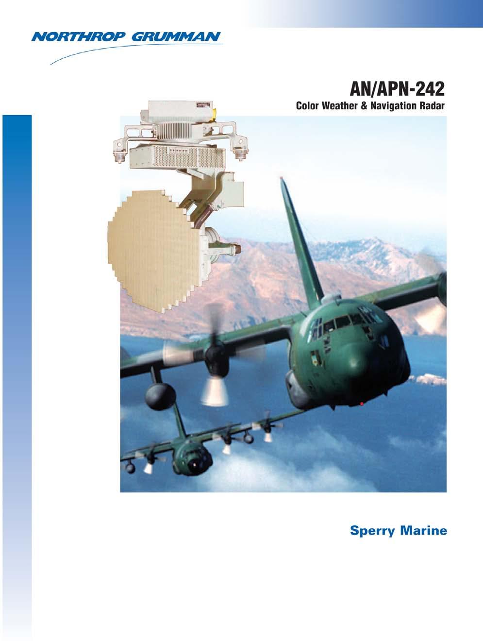
AN/APN-242 Color Weather & Navigation Radar
|
|
|
- Nickolas Palmer
- 6 years ago
- Views:
Transcription
1

 Azimuth-Range Indicator (Pilot)")


 New Video Processor (Fits PP1073 Location) MIL-STD-1553B & Analog")


.")

 savings.")
2 AN/APN-242 Color Weather & Navigation Radar Form, Fit and Function Replacement for the APN-59 Radar Previous Configuration: APN-59 Antenna Stabilization Data Generator Antenna Subsystem Radar Receiver Transmitter Fans To Nav Computer Generator Synchronizer Radar Set Electronic Marker Generator Electronic Synchronizer Power Supply Power Supply & Display Subsystem Antenna Azimuth-Range Indicator (Navigator) Azimuth-Range Indicator (Pilot) Today s Consolidated Configuration: APN-242 Stabilization From Aircraft System New Receiver Transmitter New Pilot s Display New Antenna Weather Detection and Avoidance Detects weather with full color, black and white, or green displays of storms out to 240NM. Terrain Mapping and Navigation High resolution ground mapping mode with latitude/longitude stabilized electronic cursor to provide range and azimuth information to waypoint. Aircraft Detection Skin paints fighter aircraft at extended ranges through intervening rain showers concurrent with other operating modes. New Antenna Interface Box (Fits ECA Location) New Video Processor (Fits PP1073 Location) MIL-STD-1553B & Analog Interfaces (Overlays & Other System Inputs) Beacon and IFF Interrogation Detects airborne and ground beacons and optionally interrogates IFF equipped aircraft out to 100NM. Dramatically Improved System Mean- Time Between Failure Rate As APN-59 systems age, radar failures are becoming a leading cause of C-130 and C- 135 aircraft downtime. Today s APN-242 has half the number of line replaceable units (LRUs) and greater than an order of magnitude improvement in system meantime between failures (MTBF). New Navigator Azimuth-Range Indicator New Radar/NAV Panel Field Installation By Unit Level Maintenance In A Day No depot required. APN-242 can be installed using existing radar cabling, connections and mounts without aircraft modification. Pays for itself From operations and maintenance (O&M) savings. In production Off the shelf and in inventory for immediate deliveries. APN-59E/F APN-242 System MTBF Under 100 Hours Greater than 1000 hours Weight 244 lbs. 205 lbs. Power Consumption 1600W 800W Antenna Beam Switching Mechanical Electronic (Instantaneous) Antenna Stabilization Internal Gyro Inertial Reference System Cooling External Fans None Required Daylight Viewable Non-Fade Display None Standard Electronic Cursor with Integrated Graphics Overlay None Standard Color Weather Contour Map None Standard Built-In Test None Standard
3 The Antenna Unit The APN-242 Antenna Unit consists of a flat plate array and mounting pedestal and uses the existing APN-59 installation and mounting brackets. The array element improves target detection ranges and is electronically controlled to permit instantaneous fan/pencil beam switching. The antenna rotates freely through 360º and is connected to existing aircraft attitude reference systems to provide antenna stabilization throughout the normal range of aircraft maneuvers. High reliability is achieved through the elimination of all gears, improving antenna MTBF by a factor of fifty. The Receiver/Transmitter The APN-242 Receiver/Transmitter uses a lower power solid state design, a low-noise receiver and a three to one component reduction to improve system performance and greatly increase reliability. Transmit power is generated by a 10,000 hour service life state-of-the-art magnetron with digitally controlled pulse width, pulse repetition rates, intermediate frequency (IF) and video amplification, mode switching and built-in-test (BIT). The Display Group The ASN-165 Display Group provides a vivid color or monochrome radar image in ambient lighting. These high resolution displays are overlaid with aircraft navigation data such as true heading, ground speed and track angle error. A latitude/longitude stabilized cursor is provided to aid drop zone and waypoint identification. Depending on the aircraft mission design series, data from the station keeping equipment (SKE), self-contained navigation system (SCNS) and traffic collision avoidance system (TCAS) can be integrated and displayed. In the green mode, the displays are night vision goggle compatible.
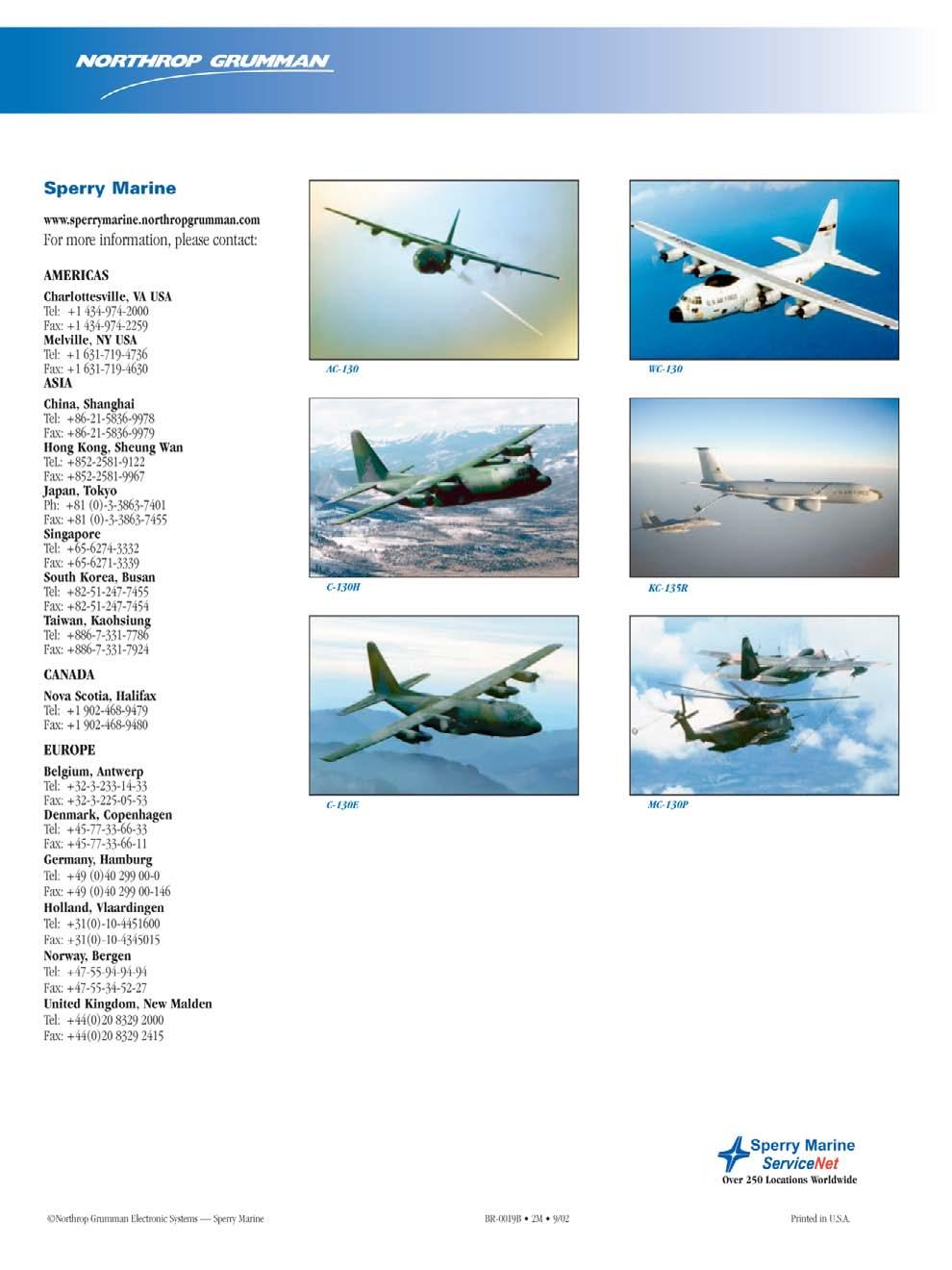
4 Sperry Marine Coastal Navigation Weather and Storm Center Detection Enhanced Terrain Mapping Beacon and IFF Interrogation Aircraft Detection RC-135 In Production For USAF All screens are actual video capture from cockpit videotape APN-242 Modes of Operation

 Receiver Noise Figure 6.")
, automatically selected for different ranges and functions Pulse Repetition Frequency.")


5 Sperry Marine APN-242 Dimensions and Operating Parameters 35.76in/908mm 8.29in/211mm MOUNTING SURFACE DIAMETER SWEEP VOLUME RADIUS 17.88IN/454MM MAX 25.75in/ 654mm Max 12.50in/318mm 15.1 HEIGHT 18.00in/457mm 8.5 in/216mm 5.7 in/145mm ALL DIMENSIONS AND WEIGHTS ARE APPROXIMATE Operating Parameters Frequencies Radar operation: X-band 9375 ±10 MHz; beacon reception 9310 MHz Transmitted Power 25 kw nominal peak (new high reliability magnetron) Receiver Noise Figure 6.5 db nominal Range Scale 2.5 to 20 (2.5 NM increments), 25, 30, 50, 100 and 240 NM Pulse Length Multiple lengths (0.2, 0.8, 2.35 and 4.5 microseconds), automatically selected for different ranges and functions Pulse Repetition Frequency Hz Hz 2.35 µsec@ 350 Hz Hz Scanning Features 360-degree scan rates: 12 rpm on long range functions; 45 rpm on short range functions Sector scan: approximately 90 degrees centered about forward position Antenna Beam Selection Pencil or fan beam, both with 3- degree azimuth beamwidth and instantaneous electronic switching Antenna Stabilization Stabilized to existing aircraft reference throughout a range of ±15 degrees pitch and ±30 degrees roll Navigation Features Manual electronic cursor with latitude/longitude or range/bearing readout; latitude/longitude stabilized for fly to waypoint capability Maximum Operating Conditions Operating Temperature (Internal Equipment) Parameter Normal Operation Navigator & Pilot Indicators -15 to +55 C Antenna Interface Unit -55 to +55 C Video Processor -40 to +55 C Receiver/Transmitter & Antenna Operating Temperature -55 to +55 C Storage Temperature -57 to +85 C Aircraft Altitude (Uninhabited) -1,500 to 50,000 feet Cabin Pressure (Inhabited) 0 to 8,000 feet Maximum Level Flight Speed 400 knots EAS Vertical Speed ± 1,500 ft/min Pitch Angle ± 15 Bank Angle ± 30 (stabilized) ± 60 (unstabilized) LRU Weight/Size Unit Dimensions Weight Antenna 35.8 x 35.8 x 34.0 in 69.0 lbs x x mm 31.4 kg Antenna Interface 6.5 x 5.5 x 10.7 in 7.0 lbs x x mm 3.2 kg Receiver/Transmitter 15.3 in dia in ht lbs mm dia., mm ht kg Video Processor 7.75 x 7.75 x 12.3 in 25.0 lbs x x mm 11.3 kg Pilot s Indicator 6.5 x 6.5 x 12.0 in 12.0 lbs x x mm 5.4 kg Navigator s Indicator 8.5 x 10.0 x 12.8 in 21.0 lbs x x mm 9.5 kg Navigator s 6.0 x 10.0 x 3.8 in 5.5 lbs x x 95.0 mm 2.5 kg
6
ARCHIVED REPORT. For data and forecasts on current programs please visit or call
 Radar Forecast ARCHIVED REPORT For data and forecasts on current programs please visit www.forecastinternational.com or call +1 203.426.0800 Outlook Barring further developments, this report will be archived
10 Secondary Surveillance Radar
 10 Secondary Surveillance Radar As we have just noted, the primary radar element of the ATC Surveillance Radar System provides detection of suitable targets with good accuracy in bearing and range measurement
F-104 Electronic Systems
 Information regarding the Lockheed F-104 Starfighter F-104 Electronic Systems An article published in the Zipper Magazine # 49 March-2002 Author: Country: Website: Email: Theo N.M.M. Stoelinga The Netherlands
AIRCRAFT AVIONIC SYSTEMS
 AIRCRAFT AVIONIC SYSTEMS B-777 cockpit Package C:\Documents and ettings\administrato Course Outline Radio wave propagation Aircraft Navigation Systems - Very High Omni-range (VOR) system - Instrument Landing
Modular Test Approaches for SSR Signal Analysis in IFF Applications
 Modular Test Approaches for SSR Signal Analysis in IFF Applications Military radar applications call for highly specialized test equipment Radar signal analysis applications require highly specialized
E600 Series II Portable, Tactical Weather Radar System
 E600 Series II Portable, Tactical Weather Radar System E600 Tactical Weather Radar System Used as a tactical unit by the U.S. Military, the E600 Series II is the most portable weather radar system on
39N6E KASTA-2E2 Low-Altitude 3D All-Round Surveillance Radar
 39N6E KASTA-2E2 Low-Altitude 3D All-Round Surveillance Radar The Kasta-2E2 low-altitude 3D all-round surveillance radar is designed to control airspace and to perform automatic detection, range/azimuth/altitude
EE Chapter 14 Communication and Navigation Systems
 EE 2145230 Chapter 14 Communication and Navigation Systems Two way radio communication with air traffic controllers and tower operators is necessary. Aviation electronics or avionics: Avionic systems cover
AIR ROUTE SURVEILLANCE 3D RADAR
 AIR TRAFFIC MANAGEMENT AIR ROUTE SURVEILLANCE 3D RADAR Supplying ATM systems around the world for more than 30 years indracompany.com ARSR-10D3 AIR ROUTE SURVEILLANCE 3D RADAR ARSR 3D & MSSR Antenna Medium
2. Radar receives and processes this request, and forwards it to Ground Datalink Processor (in our case named GRATIS)
") 1 Short Description The Traffic Information Service (TIS) provides information to the cockpit via data link that is similar to VFR radar traffic advisories normally received over voice radio. TIS is intended
1 Short Description The Traffic Information Service (TIS) provides information to the cockpit via data link that is similar to VFR radar traffic advisories normally received over voice radio. TIS is intended
Broadband 4G Radar. Reinventing Radar
 2012 Broadband 4G Radar Reinventing Radar Reinventing Radar Simrad Yachting has pioneered a new standard of Dome Radars the first with the award-winning BR24, and more recently, with the Broadband 3G Radar.
SD3-60 AIRCRAFT MAINTENANCE MANUAL SYSTEM (BENDIX RDR 1150 COLOUR) - DESCRIPTION & OPERATION
 - DESCRIPTION & OPERATION") AMM 41.0.0.0WEATHER RADAR SYSTEM (BENDIX RDR 1150 COLOUR) - DESCRIPTION & OPERATION 1. Description A. General The Weather Radar System, Bendix type RDR-1150 (colour), is installed to provide continuous
AMM 41.0.0.0WEATHER RADAR SYSTEM (BENDIX RDR 1150 COLOUR) - DESCRIPTION & OPERATION 1. Description A. General The Weather Radar System, Bendix type RDR-1150 (colour), is installed to provide continuous
NEW FOR Radar. Broadband. The evolution of the radar revolution.
 NEW FOR 2011 Broadband Radar The evolution of the radar revolution. The evolution of the radar revolution. The original BR24 Broadband Radar, the frequency modulated continuous wave (FMCW) radar, has captured
Weather Radar Systems. General Description
 General Description Our weather radars are designed for precipitation monitoring at both regional and urban scales. They can be advantageously used as gap filler of existing radar networks particularly
AT01 AIRPLANE FLIGHT MANUAL
 Table of Contents Supplement AVE12 1. Section 1 General AVE12 3 2. Section 2 Operating Limitations AVE12 3 3. Section 3 Emergency Procedures AVE12 3 4. Section 4 Normal Procedures AVE12 4 5. Section 5
ELDES / METEK Weather Radar Systems. General Description
 General Description Our weather radars are designed for precipitation monitoring at both regional and urban scales. They can be advantageously used as gap fillers of existing radar networks particularly
HALS-H1 Ground Surveillance & Targeting Helicopter
 ARATOS-SWISS Homeland Security AG & SMA PROGRESS, LLC HALS-H1 Ground Surveillance & Targeting Helicopter Defense, Emergency, Homeland Security (Border Patrol, Pipeline Monitoring)... Automatic detection
AIMS Radar Specifications
 Transmitted Frequency: Peak Radiated Power: Average Power: Antenna Beamwidth: 9.23 GHz 1 Watt (Optional 2 to 80 Watts) 6.25 microwatts up to 0.4 watts; < 1 milliwatt for most applications Fast-Scan (rotating):
Reinventing Radar SIMRAD-YACHTING.COM
 2012 Broadband 4G Radar Reinventing Radar SIMRAD-YACHTING.COM Reinventing Radar Simrad Yachting has pioneered a new standard of dome radar, first with the award-winning BR24, and more recently with the
RADAR CHAPTER 3 RADAR
 RADAR CHAPTER 3 RADAR RDF becomes Radar 1. As World War II approached, scientists and the military were keen to find a method of detecting aircraft outside the normal range of eyes and ears. They found
Copyrighted Material - Taylor & Francis
 22 Traffic Alert and Collision Avoidance System II (TCAS II) Steve Henely Rockwell Collins 22. Introduction...22-22.2 Components...22-2 22.3 Surveillance...22-3 22. Protected Airspace...22-3 22. Collision
Target intensity is shown in colour shades to assist the operator in differentiating between large and small vessels and weather severity.
 SWR1 - RADAR SCANNER (1 2Kw 24NM 0,9 Feet) maybe the smallest in the Seiwa range of radars but SWR-1 comes with the same host of features as it larger relatives providing a safer navigation in all weather
SURFACE MOVEMENT RADAR
 SMR_AF.fh11 24/2/09 15:45 P gina 1 C M Y CM MY CY CMY K Supplying ATM systems around the world for more than 30 years Friendly user interface to manage all configuration parameters indracompany.com Able
Characteristics and protection criteria for radars operating in the aeronautical radionavigation service in the frequency band
 Recommendation ITU-R M.2008 (03/2012) Characteristics and protection criteria for radars operating in the aeronautical radionavigation service in the frequency band 13.25-13.40 GHz M Series Mobile, radiodetermination,
ARCHIVED REPORT. For data and forecasts on current programs please visit or call
 Radar Forecast ARCHIVED REPORT For data and forecasts on current programs please visit www.forecastinternational.com or call +1 203.426.0800 ASR-23SS - Archived 08/2003 Outlook Production complete Procured
Helicopter Aerial Laser Ranging
 Helicopter Aerial Laser Ranging Håkan Sterner TopEye AB P.O.Box 1017, SE-551 11 Jönköping, Sweden 1 Introduction Measuring distances with light has been used for terrestrial surveys since the fifties.
MK-XII/A IFF Transponders
 DEFENSE and SECURITY MK-XII/A IFF Transponders Defense and security in five continents indracompany.com TXP-2000 TXP-2000N TXP-25S5 MK-XII/A IFF Transponders TXP-2000 A new family of transponders has been
Basic Radar Definitions Introduction p. 1 Basic relations p. 1 The radar equation p. 4 Transmitter power p. 9 Other forms of radar equation p.
 Basic Radar Definitions Basic relations p. 1 The radar equation p. 4 Transmitter power p. 9 Other forms of radar equation p. 11 Decibel representation of the radar equation p. 13 Radar frequencies p. 15
CHAPTER 1 INTRODUCTION
 1 CHAPTER 1 INTRODUCTION In maritime surveillance, radar echoes which clutter the radar and challenge small target detection. Clutter is unwanted echoes that can make target detection of wanted targets
RECOMMENDATION ITU-R S.1340 *,**
 Rec. ITU-R S.1340 1 RECOMMENDATION ITU-R S.1340 *,** Sharing between feeder links the mobile-satellite service and the aeronautical radionavigation service in the Earth-to-space direction in the band 15.4-15.7
PROFESSIONAL RADIOFREQUENCY TECHNOLOGY SOLUTIONS
 PROFESSIONAL RADIOFREQUENCY TECHNOLOGY SOLUTIONS AIR TRAFFIC CONTROL BROADCASTING DEFENCE SCIENTIFIC INSTALLATIONS S RYMSA has been leading the market thanks to its RF technology products for more than
RECOMMENDATION ITU-R S.1341*
 Rec. ITU-R S.1341 1 RECOMMENDATION ITU-R S.1341* SHARING BETWEEN FEEDER LINKS FOR THE MOBILE-SATELLITE SERVICE AND THE AERONAUTICAL RADIONAVIGATION SERVICE IN THE SPACE-TO-EARTH DIRECTION IN THE BAND 15.4-15.7
Simrad R5000 IMO/Solas Type Approved Radar Systems
 Simrad R5000 IMO/Solas Type Approved Radar Systems R5000 www.navico.com/commercial R5000 Radar Systems SIMRAD R5000 Radar Systems feature a modular plug & play design making it easy to create a cost effective
RESOLUTION A.820(19) adopted on 23 November 1995 PERFORMANCE STANDARDS FOR NAVIGATIONAL RADAR EQUIPMENT FOR HIGH-SPEED CRAFT
 adopted on 23 November 1995 PERFORMANCE STANDARDS FOR NAVIGATIONAL RADAR EQUIPMENT FOR HIGH-SPEED CRAFT") INTERNATIONAL MARITIME ORGANIZATION A 19/Res. 820 15 December 1995 Original: ENGLISH ASSEMBLY 19th session Agenda item 10 NOT TO BE REMOVED \ FROM THE IMO LIBRARY RESOLUTION A.820(19) adopted on 23 November
INTERNATIONAL MARITIME ORGANIZATION A 19/Res. 820 15 December 1995 Original: ENGLISH ASSEMBLY 19th session Agenda item 10 NOT TO BE REMOVED \ FROM THE IMO LIBRARY RESOLUTION A.820(19) adopted on 23 November
Electronic Scanning Antennas Product Information
 MICROWAVE APPLICATIONS GROUP Electronic Scanning Antennas Product Information (MAG) has a proven record of creativity and innovation in microwave component and subsystem design for government, military,
ARCHIVED REPORT. APQ-164(V) - Archived 11/97. Outlook. Orientation. No Production Forecast. AN Equipment Forecast
 - Archived 11/97. Outlook. Orientation. No Production Forecast. AN Equipment Forecast") AN Equipment Forecast ARCHIVED REPORT For data and forecasts on current programs please visit www.forecastinternational.com or call +1 203.426.0800 APQ-164(V) - Archived 11/97 Outlook In service; on-going
AN Equipment Forecast ARCHIVED REPORT For data and forecasts on current programs please visit www.forecastinternational.com or call +1 203.426.0800 APQ-164(V) - Archived 11/97 Outlook In service; on-going
RADAR CHAPTER 3 SEARCH RADAR SYSTEM
 CHAPTER 3 RADAR As an avionics supervisor, you must be knowledgeable of the operation principles of various complex search radars, fire control radars, IFF sets, and the associated peripheral equipment.
Naval Surveillance Multi-beam Active Phased Array Radar (MAARS)
") Naval Surveillance Multi-beam Active Phased Array Radar (MAARS) MAARS MAARS purpose: MAARS is multimode C-band acquisition radar for surveillance and weapon assignment. It perform automatic detection,
Naval Surveillance Multi-beam Active Phased Array Radar (MAARS) MAARS MAARS purpose: MAARS is multimode C-band acquisition radar for surveillance and weapon assignment. It perform automatic detection,
Introduction to: Radio Navigational Aids
 Introduction to: Radio Navigational Aids 1 Lecture Topics Basic Principles Radio Directional Finding (RDF) Radio Beacons Distance Measuring Equipment (DME) Instrument Landing System (ILS) Microwave Landing
Recommendation ITU-R M (01/2015)
") Recommendation ITU-R M.1638-1 (01/2015) Characteristics of and protection criteria for sharing studies for radiolocation (except ground based meteorological radars) and aeronautical radionavigation radars
Recommendation ITU-R M.1638-1 (01/2015) Characteristics of and protection criteria for sharing studies for radiolocation (except ground based meteorological radars) and aeronautical radionavigation radars
FS5000 COMSTRON. The Leader In High Speed Frequency Synthesizers. An Ideal Source for: Agile Radar and Radar Simulators.
 FS5000 F R E Q U E N C Y S Y N T H E S I Z E R S Ultra-fast Switching < 200 nsec Wide & Narrow Band Exceptionally Clean An Ideal Source for: Agile Radar and Radar Simulators Radar Upgrades Fast Antenna
AN/APS Only the control unit, indicator scopes, indicator amplifiers, and junction box are mounted within the aircraft.
 AN/APS-4 Figure 2-54.--With the APS-4 set for search its antenna executes a two-line scan. When the equipment is set for intercept the scanned area is broadened vertically, the antenna executing a four-line
Exam questions: AE3-295-II
 Exam questions: AE3-295-II 1. NAVIGATION SYSTEMS (30 points) In this question we consider the DME radio beacon. [a] What does the acronym DME stand for? (3 points) DME stand for Distance Measuring Equipment
Mode S Skills 101. OK, so you ve got four basic surveillance skills, you ve got the: ATCRBS Skills Mode S Skills TCAS Skills ADS-B skills
 Mode S Skills 101 OK, so you ve got four basic surveillance skills, you ve got the: ATCRBS Skills Mode S Skills TCAS Skills ADS-B skills Fisher Fisher Slide 1 853D ELECTRONIC SYSTEMS GROUP MODE S 101 Prepared
RECOMMENDATION ITU-R SA.1624 *
 Rec. ITU-R SA.1624 1 RECOMMENDATION ITU-R SA.1624 * Sharing between the Earth exploration-satellite (passive) and airborne altimeters in the aeronautical radionavigation service in the band 4 200-4 400
SUPPLEMENT REVISION CESSNA MODEL 182T
 SUPPLEMENT REVISION CESSNA MODEL 182T NAV III AVIONICS OPTION - Serials 18281228 and 18281318 thru 18281868 and 18281870 thru 18281875 PILOTS OPERATING HANDBOOK AND AIRPLANE FLIGHT MANUAL REVISION 1 1
Experiences in. Flight Inspecting GBAS
 Experiences in Flight Inspecting GBAS Thorsten Heinke Aerodata AG 1 Flight Inspection of GBAS Overview Basics Requirements Equipment Flight Inspection 2 Ground Based Augmentation System VDB Tx-Frequency
RADARPILOT 1000 Brilliant 12 and 16 Colour Radars
 RADARPILOT 1000 Brilliant 12 and 16 Colour Radars Introduction The RADARPILOT 1000 represents a milestone in technical performance, ease of operation, simple maintenance and future oriented sstem technolog.
11 Traffic-alert and Collision Avoidance System (TCAS)
") 11 Traffic-alert and Collision Avoidance System (TCAS) INSTRUMENTATION 11.1 Introduction In the early nineties the American FAA stated that civil aircraft flying in US airspace were equipped with a Traffic-alert
11 Traffic-alert and Collision Avoidance System (TCAS) INSTRUMENTATION 11.1 Introduction In the early nineties the American FAA stated that civil aircraft flying in US airspace were equipped with a Traffic-alert
Broadband 3G Radar The evolution of the radar revolution.
 Broadband 3G Radar The evolution of the radar revolution. SIMRAD-YACHTING.COM The evolution of the radar revolution. Broadband Radar a.k.a. frequency modulated continuous wave (FMCW) radar is nothing new...
Boeing MultiScan ThreatTrack Weather Radar Frequently Asked Questions. The next generation moving map (Cover Tag Line) and cabin flight system
 and cabin flight system") Boeing MultiScan ThreatTrack Weather Radar Frequently Asked Questions The next generation moving map (Cover Tag Line) and cabin flight system Boeing MultiScan WXR ThreatTrack Frequently Asked Questions
Boeing MultiScan ThreatTrack Weather Radar Frequently Asked Questions The next generation moving map (Cover Tag Line) and cabin flight system Boeing MultiScan WXR ThreatTrack Frequently Asked Questions
AIRBORNE RADAR 1944 / 1945 HEAVY CONVERSION UNITS 1661 & 1668 RAF WINTHORPE RAF BOTTESFORD 5 GROUP BOMBER COMMAND
 AIRBORNE RADAR 1944 / 1945 HEAVY CONVERSION UNITS 1661 & 1668 RAF WINTHORPE RAF BOTTESFORD 5 GROUP BOMBER COMMAND Produced by F/O James Sands RCAF Smiths Falls, Ontario, Canada February 2011 F/O James
AIRPLANE FLIGHT MANUAL AQUILA AT01. Date of Issue A.01 Initial Issue (minor change MB-AT ) all March
 all March") 0.1 LIST OF REVISIONS AND AMENDMENTS Revision Reason for Amendment/Revision Affected Pages Date of Issue A.01 Initial Issue (minor change MB-AT01-00297) all 2009 19. March 0.2 LIST OF EFFECTIVE PAGES Page
0.1 LIST OF REVISIONS AND AMENDMENTS Revision Reason for Amendment/Revision Affected Pages Date of Issue A.01 Initial Issue (minor change MB-AT01-00297) all 2009 19. March 0.2 LIST OF EFFECTIVE PAGES Page
Airborne Satellite Communications on the Move Solutions Overview
 Airborne Satellite Communications on the Move Solutions Overview High-Speed Broadband in the Sky The connected aircraft is taking the business of commercial airline to new heights. In-flight systems are
AE4-393: Avionics Exam Solutions
 AE4-393: Avionics Exam Solutions 2008-01-30 1. AVIONICS GENERAL a) WAAS: Wide Area Augmentation System: an air navigation aid developed by the Federal Aviation Administration to augment the Global Positioning
FlyRealHUDs Very Brief Helo User s Manual
 FlyRealHUDs Very Brief Helo User s Manual 1 1.0 Welcome! Congratulations. You are about to become one of the elite pilots who have mastered the fine art of flying the most advanced piece of avionics in
Orientation. Status. Available for sale. Application. terminal area. Contractors
 Radar Forecast Outlook FI estimates that Raytheon will sell about three ASR-11 radar systems in the coming decade This forecast is being driven by the United States' need to replace aging terminal-area
Precision Validation of Radar System Performance in the Field
 Precision Validation of Radar System Performance in the Field August 19, 2015 Tom Hoppin Application Specialist Component Test Division Keysight Technologies Keysight Technologies 2015 1 Precision Validation
FieldFox Handheld Education Series Part 7: Precision Validation of Radar System Performance in the Field
 FieldFox Handheld Education Series Part 7: Precision Validation of Radar System Performance in the Field FieldFox Handheld Education Series Interference Testing Cable and Antenna Measurements Calibration
MULTI-MODE MULTI MISSION RADAR
 MULTI-MODE MULTI MISSION RADAR leonardocompany.com For more information please email infomarketing@leonardocompany.com Leonardo S.p.a. Via Tiburtina, Km 12.400-00131 Rome - Italy - Tel: +39 06 41501 -
Independent Position Determining
 GENERAL Independent Position Determining 34-40: INDEPENDENT POSITION DETERMINING 1. General This section covers that portion of the system which provides information to determine position from sources
Master Parts Inventory
 ID Nomenclature Part Alternate P/N Manufacturer 44 Automatic Annunicator 103500 Sunstrand MTA 554 47 Tape Reproducer 108002 0004JL 980 9000 004 Sundtrand 201AACB 97 Tape Reproducer 108002 0004JL 980 9000
ARCHIVED REPORT. For data and forecasts on current programs please visit or call
 Radar Forecast ARCHIVED REPORT For data and forecasts on current programs please visit www.forecastinternational.com or call +1 203.426.0800 SPS-64(V) - Archived 5/99 Outlook In service, ongoing logistics
Radar observables: Target range Target angles (azimuth & elevation) Target size (radar cross section) Target speed (Doppler) Target features (imaging)
 Target size (radar cross section) Target speed (Doppler) Target features (imaging)") Fundamentals of Radar Prof. N.V.S.N. Sarma Outline 1. Definition and Principles of radar 2. Radar Frequencies 3. Radar Types and Applications 4. Radar Operation 5. Radar modes What What is is Radar? Radar?
Fundamentals of Radar Prof. N.V.S.N. Sarma Outline 1. Definition and Principles of radar 2. Radar Frequencies 3. Radar Types and Applications 4. Radar Operation 5. Radar modes What What is is Radar? Radar?
360 inches (915 cm) 240 inches (610 cm) 120 inches (305 cm) 240 inches is the recommended pole length, 360 inches is the recommended free space area
 240 inches (610 cm) 120 inches (305 cm) 240 inches is the recommended pole length, 360 inches is the recommended free space area") FML C/P FM Antenna Right hand C/P Polarization Low wind load area Up to 1 kw Rating per bay Omni-directional Up to 8 kw input per array with power divider options The FML series of antennas are narrow
FML C/P FM Antenna Right hand C/P Polarization Low wind load area Up to 1 kw Rating per bay Omni-directional Up to 8 kw input per array with power divider options The FML series of antennas are narrow
Black Marlin radar systems may be purchased with a flat-top radome for mounting cameras on
 SPECIFICATIONS The Black Marlin is DMT s midrange security radar system. It may be used to search and track threats from land and sea. This radar is an X- Band, pulsed- Doppler system that operates in
ALR-400 RADAR WARNING RECEIVER
 AIBORNE DEFENSE SYSTEMS RADAR WARNING RECEIVER Defense and security systems in five continents indracompany.com RADAR WARNING RECEIVER Technical description leading edge field proven wideband digital reception
HEAVY-DUTY HIGH PERFORMANCE RASTERSCAN RADARS/ARPAS
 Complying with IMO and IEC standards for installation after 1.1.1999 HEAVY-DUTY HIGH PERFORMANCE RASTERSCAN RADARS/ARPAS Models FR/FAR-28x5 series The future today with FURUNO's electronics technology.
WEATHER RADAR CORE PRECIPITATION WRCP-1
 WEATHER RADAR CORE PRECIPITATION WRCP-1 DESCRIPTION The mini weather radar WRCP-1 is a small, high technology unit which is portable or easily mounted. It has a reach of 40-50 km, and is very accurate
INTERNATIONAL STANDARD
 INTERNATIONAL STANDARD IEC 60936-2 First edition 1998-10 Maritime navigation and radiocommunication equipment and systems Radar Part 2: Shipborne radar for high-speed craft (HSC) Methods of testing and
TCAS Functioning and Enhancements
 TCAS Functioning and Enhancements Sathyan Murugan SASTRA University Tirumalaisamudram, Thanjavur - 613 402. Tamil Nadu, India. Aniruth A.Oblah KLN College of Engineering Pottapalayam 630611, Sivagangai
RDR-1600 WEATHER RADAR SYSTEM INSTALLATION MANUAL
 RDR-1600 WEATHER RADAR SYSTEM INSTALLATION MANUAL April 2005 Prepared by: TELEPHONICS CORPORATION 815 Broad Hollow Road Farmingdale, New York 11735 USA TM106601 (4/05) Revision 3 RDR-1600 WEATHER RADAR
Impact of ATC transponder transmission to onboard GPS-L5 signal environment
 SCRSP-WG IP-A10 18 May 2006 SURVEILLANCE AND CONFLICT RESOLUTION SYSTEMS PANEL (SCRSP) TENTH MEETING WG-A Montreal, May, 2006 WG-A Agenda Item 9 Any Other Bussiness Impact of ATC transponder transmission
Radar Reprinted from "Waves in Motion", McGourty and Rideout, RET 2005
 Radar Reprinted from "Waves in Motion", McGourty and Rideout, RET 2005 What is Radar? RADAR (Radio Detection And Ranging) is a way to detect and study far off targets by transmitting a radio pulse in the
The Old Cat and Mouse Game Continues
 The Old Cat and Mouse Game Continues or, How Advances in Radar Development Drive Testing Requirements for Next Generation EW Systems by: Walt Schulte Agilent Technologies Microwave and Communications Division
NAVIGAT Fiber-Optic Gyrocompass and Attitude Reference System. Sperry Marine. The Dynamic Solution for a Demanding Challenge
 NAVIGAT 2100 Fiber-Optic Gyrocompass and Attitude Reference System Sperry Marine The Dynamic Solution for a Demanding Challenge NAVIGAT 2100 Fiber-Optic Gyrocompass and Attitude Fiber-Optic Sensor Unit
QUICK START GUIDE flywithsentry.com
 QUICK START GUIDE flywithsentry.com LED INDICATORS ADS-B Receiving from multiple towers Receiving from one tower No reception Carbon Monoxide (CO) Monitor Normal Caution Danger* GPS Good fix Bad fix No
PHOTOGRAMMETRIC RESECTION DIFFERENCES BASED ON LABORATORY vs. OPERATIONAL CALIBRATIONS
 PHOTOGRAMMETRIC RESECTION DIFFERENCES BASED ON LABORATORY vs. OPERATIONAL CALIBRATIONS Dean C. MERCHANT Topo Photo Inc. Columbus, Ohio USA merchant.2@osu.edu KEY WORDS: Photogrammetry, Calibration, GPS,
Multi-function Phased Array Radars (MPAR)
") Multi-function Phased Array Radars (MPAR) Satyanarayana S, General Manager - RF systems, Mistral Solutions Pvt. Ltd., Bangalore, Karnataka, satyanarayana.s@mistralsolutions.com Abstract In this paper,
Multi-function Phased Array Radars (MPAR) Satyanarayana S, General Manager - RF systems, Mistral Solutions Pvt. Ltd., Bangalore, Karnataka, satyanarayana.s@mistralsolutions.com Abstract In this paper,
Introduction. Traffic Symbology. System Description SECTION 12 ADDITIONAL FEATURES
 12.2 Traffic Advisory Systems (TAS) Introduction All information in this section pertains to the display and control of the Garmin GNS 430/GTS 800 interface. NOTE: This section assumes the user has experience
AIR SURVEILLANCE FOR SMART LANDING FACILITIES IN THE SMALL AIRCRAFT TRANSPORATION SYSTEM. By Eric J. Shea
 AIR SURVEILLANCE FOR SMART LANDING FACILITIES IN THE SMALL AIRCRAFT TRANSPORATION SYSTEM By Eric J. Shea Thesis submitted to the Faculty of Virginia Polytechnic Institute and State University (Virginia
ADS-B and WFP Operators. Safety Advantages Security Concerns. Thomas Anthony Director U.S.C. Aviation Safety and Security Program ADS-B
 ADS-B and WFP Operators Safety Advantages Security Concerns Thomas Anthony Director U.S.C. Aviation Safety and Security Program ADS-B How can ADS-B be useful for Humanitarian Air Operation? Are there security
BYU SAR: A LOW COST COMPACT SYNTHETIC APERTURE RADAR
 BYU SAR: A LOW COST COMPACT SYNTHETIC APERTURE RADAR David G. Long, Bryan Jarrett, David V. Arnold, Jorge Cano ABSTRACT Synthetic Aperture Radar (SAR) systems are typically very complex and expensive.
Chapter 3 Army Air Defense Control Systems
 Chapter 3 Army Air Defense Control Systems The exchange of information between missile fire units and command posts must be instantaneous. Army AD units require timely and continuous information on the
Space Frequency Coordination Group
 Space Frequency Coordination Group Report SFCG 38-1 POTENTIAL RFI TO EESS (ACTIVE) CLOUD PROFILE RADARS IN 94.0-94.1 GHZ FREQUENCY BAND FROM OTHER SERVICES Abstract This new SFCG report analyzes potential
NAVIGATION INTRUMENTATION ADF
 1. Introduction NAVIGATION INTRUMENTATION ADF The Automatic Direction Finding (ADF) equipment on-board of aircraft is used together with the Non Directional Beacon (NDB) transmitters installed on the ground.
DYNAMO Aircraft Operations
 DYNAMO Aircraft Operations Aircraft: NOAA WP-3D, "Kermit" N42RF Flight hours: 105 science mission hours + 70 ferry hours Aircraft operation base: Diego Garcia (7.3 S, 72.5 E) Operation period: 45 days
O T & E for ESM Systems and the use of simulation for system performance clarification
 O T & E for ESM Systems and the use of simulation for system performance clarification Dr. Sue Robertson EW Defence Limited United Kingdom e-mail: sue@ewdefence.co.uk Tuesday 11 March 2014 EW Defence Limited
Product Information. Page 1 of 10
 Product Information RT-1000.C Page 1 of 10 Edited by: RHOTHETA Elektronik GmbH Kemmelpark Dr.-Ingeborg-Haeckel-Str.1 82418 Murnau Germany : +49 8841 / 4879-0 : +49 8841 / 4879-14 Homepage: www.rhotheta.de
Keysight Technologies Techniques for Precision Validation of Radar System Performance in the Field
 Keysight Technologies Techniques for Precision Validation of Radar System Performance in the Field Using FieldFox handheld analyzers Application Note This application note provides an overview of field
RECOMMENDATION ITU-R M * Technical characteristics for search and rescue radar transponders
 Rec. ITU-R M.628-4 1 RECOMMENDATION ITU-R M.628-4 * Technical characteristics for search and rescue radar transponders (Questions ITU-R 28/8 and ITU-R 45/8) (1986-1990-1992-1994-2006) Scope This Recommendation
Reducing Test Flights Using Simulated Targets and a Carefully Chosen Set-up
 Reducing Test Flights Using Simulated Targets and a Carefully Chosen Set-up Edition: 001 Date: 18-FEB-09 Status: Released DOCUMENT DESCRIPTION Document Title Reducing Test Flights: Using Simulated Targets
A Review of Vulnerabilities of ADS-B
 A Review of Vulnerabilities of ADS-B S. Sudha Rani 1, R. Hemalatha 2 Post Graduate Student, Dept. of ECE, Osmania University, 1 Asst. Professor, Dept. of ECE, Osmania University 2 Email: ssrani.me.ou@gmail.com
ATS 351 Lecture 9 Radar
 ATS 351 Lecture 9 Radar Radio Waves Electromagnetic Waves Consist of an electric field and a magnetic field Polarization: describes the orientation of the electric field. 1 Remote Sensing Passive vs Active
Flight Detector Indicator
 Flight Detector Indicator Part No: 777-1224-003 Components Maintenance Manual No: 34-25-12 By Soumyadeep Das Raj shekhar Chatterjee Purpose of equipment: The flight detector indicator (FDI) is a part of
AB Drives AN/ARC-182(V) UHF/VHF Airborne. Key Features
 UHF/VHF Airborne. Key Features") UHF/VHF Airborne Key Features 11,600 channels, 25-kHz spacing Direct MIL-STD-1553B multiplex system control 28 or 30 preset channels, nonvolatile Automatic direction finding compatible memory Four guard
UHF/VHF Airborne Key Features 11,600 channels, 25-kHz spacing Direct MIL-STD-1553B multiplex system control 28 or 30 preset channels, nonvolatile Automatic direction finding compatible memory Four guard
Technical Standard Order
 Department of Transportation Federal Aviation Administration Aircraft Certification Service Washington, DC TSO-C74c Date: 2/20/73 Technical Standard Order Subject: TSO-C74c, AIRBORNE ATC TRANSPONDER EQUIPMENT
Synthetic Aperture Radar
 Synthetic Aperture Radar Picture 1: Radar silhouette of a ship, produced with the ISAR-Processor of the Ocean Master A Synthetic Aperture Radar (SAR), or SAR, is a coherent mostly airborne or spaceborne
MRS-1000 RADAR SYSTEM USER MANUAL
 MRS-1000 RADAR SYSTEM USER MANUAL DOCUMENT VER. 1.0 AUGUST 2015 1 2 3 CONFIGURATION 3 FEATURES 4 GENERAL INFORMATION 5 SAFETY PRECAUTIONS 5 INSTALLATION AND REMOVAL 5 MAINTENANCE 5 FUSE REPLACEMENT 6 OPERATING
3D Animation of Recorded Flight Data
 3D Animation of Recorded Flight Data *Carole Bolduc **Wayne Jackson *Software Kinetics Ltd, 65 Iber Rd, Stittsville, Ontario, Canada K2S 1E7 Tel: (613) 831-0888, Email: Carole.Bolduc@SoftwareKinetics.ca