Page 1 of 16 Magnatone Vibrato Design 4 January Contents
|
|
|
- Brenda Stafford
- 6 years ago
- Views:
Transcription
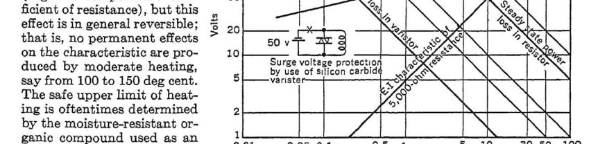
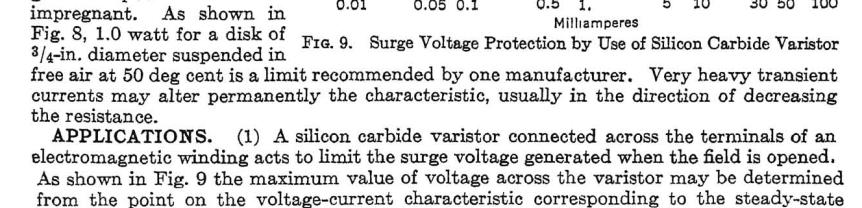
1 Page 1 of 16 Magnatone Vibrato Design 4 January 2018 This article briefly collates design information relating to a vibrato effect used in Magnatone amplifiers in the late 1950 s and early 1960 s, and describes the design of the 213 model amplifier that uses the vibrato effect. The performance of this vibrato effect circuit is specific to the model of Silicon Carbide voltage dependant resistor (varistor) used. Cloning of that varistor is of interest due to the cost of NOS parts. Schober organs used this vibrato technique, starting with a variable triode resistance, then using varistors, and finally changing to LDRs. Although varistors weren t used, the technique was also used by others. The Wurlitzer electronic vibrato technique was dominant at the time and is briefly noted. Contents Resistance-Reactance Bridge Vibrato Technique... 1 Magnatone and Bonham... 3 Varistor Information... 3 Varistor V-I measurement... 5 Cloning a Magnatone varistor... 5 Circuit Design Magnatone Signal phase modulator... 8 Low frequency oscillator Amplitude modulation Solid-state circuit cloning References and Appendices Appendix A. Schober vibrato circuits using varistors. 14 Appendix B: The Wurlitzer Vibrato Technique Resistance-Reactance Bridge Vibrato Technique In July 1953, Robert C. Moses 1 described [1] an oscilloscope phase-angle measurement technique that used a resistance-capacitance bridge to shift the phase of a signal passing through the circuit by varying R, as shown in the Figure 1 circuit. Don L. Bonham filed patent #3,146,292 in March 1954 where various phase shift circuit techniques, included Moses circuit, cycle the phase shift through nearly 180 degrees at a low frequency, such that the signal frequency being passed is modulated by the low frequency to apply a vibrato effect to the signal. Table 1 in Moses article identifies the phase angle shift range achieved with the cathodyne based RC phase shifting circuit. Moses tabulated RC products, whereas Bonham s patent #3,146,292 shows a simpler to comprehend plot of phase change for varying R/X = R/(1/ωC) = ωrc. This vibrato generation technique had the practical benefit that when the centre frequency (R/X=1) was set at about 1kHz, where the vibrato effect is maximum, then much lower and higher frequencies exhibit no vibrato (where vibrato is usually not wanted). Figure 1. Moses phase shift circuit, as Dorf and Bonham went on to use for vibrato generation. Richard Dorf used this phase-shift technique in Schober organ kits from Feb 1956 [2], initially using a 6SL7 triode as the variable resistance arm of the bridge and a CT transformer winding to generate the out of phase 1 Moses appears to have worked for Sylvania in the late 1940s to early 50 s, and then Lear Inc.
2 Page 2 of 16 Magnatone Vibrato Design 4 January 2018 signals. Dorf s US2,835,814 patent was applied for in March 1956, and covers that format, as does the nd Edition of [3]. Circa 1960, Schober s Concert and Consolette models, and the new smaller Spinet model, used varistors in circuitry similar to Magnatone s [see below]. From 1963, Schober changed to LDRs in the variable resistance arm, and used transistor circuitry and incandescent bulbs to drive the LDRs [3]. The incandescent bulb and LDR devices have thermal and time delay characteristics that modify the phase modulation response, with a square waveform simply applied across the bulb. Magnatone introduced this vibrato technique in 1957 to the Custom 200 series of guitar amps using a varistor circuit technique which Bonham filed patent #2,988,706 for in Oct Some models used two sequential stages of phase shift, which allows a greater intensity of vibrato with less non-linearity introduced, as the phase shift in each stage isn t required to move as far to the 0 and 180 degree ends of the LFO sweep. Introduced in 1961, the Hammond L100 organ (AO-41 module) uses a resistance-reactance bridge to generate vibrato, where a saturable inductor provides a variable reactance, with the resistance arm remaining fixed. The L100 organ uses three sequential stages of phase shifting and allows wet + dry mixing to give a chorus response. The X66 organ from 1967 also used saturable inductors in a 3 stage phase-shift vibrato for bass notes. Ampeg used an LDR for the variable resistance arm in two sequential vibrato phase-shift stages in the Gemini GV-22 guitar amplifier introduced in The circuit diagram from patent #2,988,706 shows how Bonham used another cathodyne circuit to modulate the varistor resistance by varying the voltage across the series connection of varistors. The split signal input phases pass through capacitor C, and through the coupling capacitors and then through the varisors with the combined signal output being capacitor coupled to the next stage. The varistors act in parallel to represent the resistance R in Moses phase shift circuit. Figure 2. Magnatone vibrato circuit by Bonham The Low Frequency Oscillator (LFO) signal drives the LFO modulator cathodyne circuit. The anode-tocathode voltage of the modulator triode increases and decreases at the LFO frequency, which increases and decreases the voltage across the series connection of the varistors, which causes R to vary. The capacitor from anode to grid in the modulator stops any signal input from being amplified by the triode.
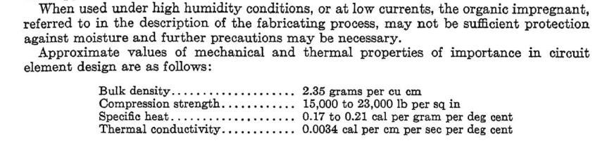
3 Page 3 of 16 Magnatone Vibrato Design 4 January 2018 Magnatone and Bonham By far the best reference for Magnatone and Bonham history is on [4]. In brief, Magnatone s origins started in Los Angeles, California in the late 1930 s. Around 1947, Magnatone branding of amplifier and guitar products started and the company name became Magna Electronics. In the 1950 s, Bonham started as a technician with Pacific Mercury Television that made Thomas Organs, progressing to an audio engineer, with Bonham filing two patents for organ circuitry. Bonham s initial vibrato patent #3,146,292 was filed March 1954 and granted Aug The interval from 54 to 64 may have resulted from the generality of the patent content, and adverse assessments along the way. Bonham s patent generalises on the specific phase shift circuit technique that Moses described less than a year earlier. Magna changed ownership to some principals from Pacific Mercury TV, and Bonham came over with the new owners in early 1957 in the role of Chief Engineer, and within a year had introduced his vibrato technique firstly in to the new Custom 200 series of guitar amps. Bonham s patent #2,988,706 was filed Oct 1958, and granted June 1961, and covers the improved vibrato circuit used in many Magnatone amp models, including the Magnatone 213 assessed on this article. In 1959, Estey acquired Magna Electronics, who continued to make Magnatone gear, as well as other branded gear. Bonham went on to look at other vibrato effect generation techniques that weren t based on the variable varistor arm in a bridge circuit. Patent #3,083,606 was filed March 1959, and granted Apr 1962, and a co-patent #3,160,695 was also filed March 1959, and granted Dec 1964, and those vibrato techniques were used in Magnatone stereo amps. It appears that Bonham had moved on from Magna by mid There are several different varistor vibrato circuits employed in Maggie models. Most are just variations of the same basic circuit. Some use a single stage modulator. Some use a dual stage cascade modulator. Varistor Information The varistor that Magnatone used was made from Silicon Carbide (SiC) using a ceramic manufacturing technique. SiC varistors were being widely used in telephone sets in the 1950s, and also for over-voltage clamping applications in electrical equipment [App.C]. Varistors for this application are specified at low currents, typically 1mA or less, and high-ish voltages of typically V. A varistor manufacturer s datasheet shows a characteristic V-I (voltage versus current) curve for a part, and the Carborundum 233BNR family curves are shown below. Apart from a non-descript model number, varistors are usually identified at a particular V-I point to assist differentiation and application selection, given that the device is a non-linear resistance. Magnatone amps appear to have been designed for a varistor with a curve that is close to the following nominal V-I points: 32V; 55V; 65V; 105V. It is understood that the Kanthal Globar (previously Ceslwld & Carborundum) 233BNR-32 was the model used by Magnatone, with the Workman FS1203 and FS605 being equivalent replacement parts [5]. Service outlets and part suppliers often had a large range of Workman and Zenith varistors for many applications. A few such parts have a V-I rating that is close to the 233BNR-32. Metrosil is the only manufacturer presently producing SiC varistors [6]. Workman FS1203: V (Zenith ) Workman FS605 Workman FS1211: V (Zenith ) Workman FS1205: V (Zenith ) Workman FR1039: V Workman FS927: V Workman FS308: V Metrosil 100-P/W/921: V; V.


4 Page 4 of 16 Magnatone Vibrato Design 4 January 2018 Figure 3. Figure 4. Original maggie varistor FR1039 : V FS-308 : V Metrosil range Figure 5.
5 Page 5 of 16 Magnatone Vibrato Design 4 January 2018 Varistor V-I measurement Varistors can t really be measured by a multimeter on its resistance setting. As indicated in the previous section, a spot measurement of V-I is applicable. For this, a variable DC supply of 50 to 100V would be appropriate, and a test circuit would use a current sense resistance (eg. 10kΩ) in series with the varistor. Alternatively, a modern insulation resistance meter with a 100Vdc range would show a resistance of 100kΩ at 1mA. To measure a characteristic curve, a higher DC voltage supply can be used with a range of additional test resistors that are placed in series with the varistor under test. I have used a 243VDC supply with a range of test resistors from 220kΩ to 24MΩ. Most test meters won t significantly influence the measurement. Measured varistor V-I levels for the same part may show at least +/-10% differences. Matching pairs of SiC varistors to put in a vibrato circuit is worthwhile to ensure the parts are nominally the same, but it is unlikely that any noticeable advantage is gained from close matching. Figure 6. Varistor V-I test circuit. Cloning a Magnatone varistor Cloning a Magnatone varistor has been achieved in two ways. A more technically accurate clone requires additional parts, as each part attempts to match a small portion of the original varistor non-linear V-I curve. A less technically accurate clone can be quite simple to make, but introduces some spectral differences as the region of mismatch between each part becomes significant, although whether that is really noticeable doesn t appear to be the case. A long series string of low voltage (<5V) zeners, along with a few resistors to trim the characteristic to match an original varistor, has shown very close performance, both in V-I characteristic curve and in spectrum analysis of a signal passed through the Magnatone circuit. Low voltage zeners exhibit a softer resistance transition as the applied voltage approaches the zener breakdown voltage than higher voltage zeners. This clone is polarised, as it is effectively a zener diode, and so needs to be correctly oriented in the Magnatone circuit. Martin Manning [7] has prepared a simpler parallel configuration of three MOVs, each with a trimming resistor. A MOV V-I curve doesn t match that of a SiC varistor, but it is a closer match than a high voltage zener, and MOVs of suitable voltage rating (22V to 82V) are easily purchased. This clone is also not polarised, so is easier to use. Limited in-situ amp testing with this clone so far indicate good equivalent performance to the original varistors. Figure 7. The results below relate to two original SiC varistors, a 3V6 zener string clone, and an early version of Martin Manning s simpler clone that used zeners. The performance of the simpler clone should be noticeably improved when using MOVs instead of zeners.


6 Page 6 of 16 Magnatone Vibrato Design 4 January 2018 Figure 8. V-I characteristic curves of clone versus two original Magnatone varistors. The V-I curves are MS Excel smoothed curves of 9 measurement points. Figure 9. Spectrum responses clone versus original varistors in Magnatone 213 varistor circuit. Original Magnatone varistor. 100Hz mains ripple sidebands noticeable around 1kHz signal. Steep fall-off of LFO sidebands.


7 Page 7 of 16 Magnatone Vibrato Design 4 January V6 zener string clone varistor. Higher levels of LFO harmonics. Broader LFO sidebands around 1kHz. 33/56/82V zener clone varistor. High levels of higher order LFO harmonics. Much broader LFO sidebands around 1kHz. Spectrum responses of a 1kHz signal through a Magnatone vibrato circuit are presented in Figure 9. Note the harmonics of the ~10Hz LFO signal, the residual 50 and 100Hz mains ripple, the 100Hz modulation sidebands of the 1kHz signal, and the second and third harmonics of the 1kHz signal. Also note that this vibrato effect adds discrete LFO sidebands to all the other signals, rather than a vibrato technique that would vary just the 1kHz as a continuous spectrum with a small bandwidth. Two spectrum plots are shown: the first plot covers the audio spectrum with one form of FFT window using the TrueRTA application; the second plot is an octave either side of the 1kHz signal, using the REW5 application with a different FFT window. Only limited in-situ amp testing has been done with these two clones, with no adverse performance.

8 Page 8 of 16 Magnatone Vibrato Design 4 January 2018 Circuit Design Magnatone 213 The Magnatone 213 circuit is shown below. After the input 12AX7 amplifier stage, and the volume and tone controls, the instrument signal is amplified by a 12AX7 triode and DC coupled to the vibrato stage signal phase modulator a 12AU7 triode cathodyne (or split-load) stage with uneven load resistances of 18kΩ to power supply A, and 82kΩ to 0V. The resistance-reactance bridge arms are formed by the 820pF reactance arm connected to the 12AU7 anode, and the resistance arm connected to the 12AU7 cathode. The variable resistance arm effectively comprises the two varistors in parallel, where the 47nF coupling capacitor in series with each varistor allows the signal to pass, and allows the varistor resistance to be modulated by the other 12AU7 triode acting as a Low Frequency Oscillator (LFO) modulator. The LFO modulator 12AU7 triode is in a cathodyne circuit with 3k9Ω cathode bias and 2M2Ω grid leak, and a load resistance of 47kΩ to A, and 43k+3.9k 47kΩ to 0V. The LFO is a simple RC phase shift oscillator using both 12AX7 triodes in parallel, with a rate pot, an output signal level pot, a remote pedal disable switch, and RC low pass filtering to the LFO modulator. PI stage Signal phase modulator LFO modulator LFO Figure 10. Magnatone 213 circuit. The combined output of the resistance-reactance bridge arms is then capacitor coupled via 470pF to a gridleak biased cathodyne PI stage driving the 6V6 pentode push-pull output stage. The PI stage presents a very high load impedance on the phase modulator output, which is needs to avoid excessive tremolo occurring. The Output stage HT supply voltage is about 350V at idle. Supply voltage at A is estimated to be about 300V, with probably 10mA through the 1k2 dropper to A, and 10+15= 25mA through the 1k2 dropper from the HT supply. Signal phase modulator A 12AU7 loadline is shown below for a 300V supply, and 82k + 18k = 100kΩ load. The previous 12AX7 triode loadline (see below) indicates that the 12AU7 grid is about 155V. With about ~ 160V across the 82kΩ cathode resistor, the cathodyne current is about 160/82k = 2.0mA, with grid bias of about -6V, and an anodecathode voltage of about 120V. Full signal voltage swing across the 12AU7 triode is generated from about 6Vpk input swing, which would generate about = 0.8mApk anode signal swing. The anode voltage swing would then be about 0.8x18 ~ 14Vpk, and the cathode voltage swing about 0.8x82 ~ 65Vpk. Maximum design level heater-cathode voltage is 200V, so this stage is exceeding that limit at peak signal voltage of ~ 220V. Each 47nF coupling capacitor, connecting to a varistor end, introduces a CR high pass filter to the resistance arm input signal, where R is approximately the connected 47kΩ resistance connected to A, or 0V. The filter corner frequency is about 70Hz, so is not really noticeable for a guitar.
9 Page 9 of 16 Magnatone Vibrato Design 4 January AU7 Figure 11. Signal modulator 12AU7 triode loadline. 12AX7 2K7 Figure AX7 triode driving the signal modulator.
10 Page 10 of 16 Magnatone Vibrato Design 4 January 2018 LFO modulator A 12AU7 loadline is shown below for a 300V supply, and 47k + 47k = 94kΩ load. With 3k9 cathode bias, the anode current is about 2mA, with about V between anode and cathode. However, the series varistor connection provides a bypass current around the triode. With an anode-cathode voltage of V, and with ~0.1mA passing through the varistors, then the bias point hardly moves at all (the anode-cathode voltage would drop a bit as less current is flowing through the triode). When the LFO modulator triode is driven towards saturation, the voltage across each varistor decreases and hence varistor resistance increases and hence bypasses less current around the triode. Similarly, when the LFO modulator triode is driven towards cut-off, the voltage across each varistor increases and hence varistor resistance falls and the varistors bypass more current around the triode. With the 12AU7 driven to saturation, the anode-cathode voltage could reduce to about 40V, ie. about 20V across each varistor. The varistor resistance is then very high (>1MΩ), and has negligible effect on the triode loadline. With the 12AU7 driven towards cut-off, the anode-cathode voltage increases towards the supply voltage and the triode resistance increases. However, the varistor resistance is falling, and effectively determines the max anode-cathode voltage level due to the 47kΩ voltage drops. The equivalent circuit then tends towards a 300V supply with 94kΩ fixed resistance in series with two varistors, where each varistor operates at about 100V and 1mA, with the 94kΩ dropping about 100V. The result is the triode loadline drooping to about a 200V x-axis crossing. The effect on the triode loadline is quite non-linear, and only really becomes noticeable for triode voltage above the idle level of about V. Assuming signal frequencies where the 47nF coupling caps are insignificant, and using Moses representation (initially assuming the electrical centre of the AC source is the mid-point of the 12AU7), then the resistance arm is the varistor resistances in parallel (each varistor initially assumed to be 55V/0.1mA = 550kΩ each). The RC time constant of 225kΩ and 820pF is about 180 Ω.uF, which achieves about 90deg output phase lag at 1kHz from the two arms. At min varistor resistance of about 100V/1mA = 100kΩ each, the RC time constant of 50kΩ and 820pF is about 41ΩuF, which achieves about 150deg output phase lag at 1kHz from the two arms. At max varistor resistance of about 25V/0.01mA = 2.5MΩ each, the RC time constant of 1.2MΩ and 820pF is about 1000ΩuF, which achieves ~10deg output phase lag at 1kHz from the two arms. Maximum design level heater-cathode voltage is 200V, so this stage likely exceeds that limit at cathode peak of about = 230V. It is likely that varistors are somewhat hygroscopic, so long-term environmental conditions may modify the max varistor resistance achieved at very low currents. Any parasitic capacitance across each varistor would reduce the phase shift affect at higher frequencies. A key aspect of the LFO modulator is that the midpoint of the series varistors stays effectively at a stable DC voltage, with little LFO signal to leak through to the output stage and speaker as LFO thumping. Any residual LFO signal would be attenuated by the 10nF-470kΩ high pass filter (~33Hz corner frequency) to each 6V6, and then by the push-pull symmetry.
11 Page 11 of 16 Magnatone Vibrato Design 4 January AU7 3K9 Figure 13. LFO modulator 12AU7 triode loadline. Low frequency oscillator The LFO is a single amplifier stage (itself providing 180 degrees of phase shift) and a three CR feedback phase-shift network (providing a further 180 degrees phase shift, = 360 degrees total shift). The total loop gain is made greater than unity using an amplifier valve with effective gain >29. A fairly large anode resistor is used with the 12AX7, which would maximize gain and output swing. The output signal becomes more distorted with valve gain, and so may be reasonably high with the 12AX7. The 213, 440, 480 models use a 1k cathode bias resistor with a significant level of grid-leak bias from the 3M3Ω, and approx loadline shown below. Only the Magnatone circuits add a very small level (0.1uF) of cathode bias decoupling. The remainder of Magnatone amps use just grid-leak biasing (which is likely to cause some variation in performance). Two RC filters (380k/4n7 and 330k/4n7) with 100Hz corner frequency are used to attenuate signal band harmonics without attenuating the LFO fundamental or its lower order harmonics.

12 Page 12 of 16 Magnatone Vibrato Design 4 January AX7 1K Approx grid leak position Figure 14. LFO 12AX7 triode loadline. Amplitude modulation Part of the perceived advantage of the Magnatone vibrato effect appears to be that it also introduces some tremolo amplitude modulation along with the frequency modulation. The plot on the right is the amplifier output signal with the vibrato circuit using standard varistors. The plot time-frame shows the vibrato frequency, with the 1kHz signal showing as the solid part. The plot is when LFO depth pot is at maximum setting in this particular amp. At lower pot settings, the amplitude modulation is much more sinusoidal. Varistors at minimum resistance Varistors at maximum resistance Figure 15. 1kHz tone signal through Magnatone circuit. The amplitude modulated signal is at a maximum level when the varistor resistance is at its lowest value due to the summing of voltages from the C and R arms of the bridge circuit. The flat topping effect indicates that the limit of effective phase shift has been reached. In Figure 1, the phase shift variation reaches a practical limit when R/X = ωrc becomes too small, or too large. This may be why Magnatone introduced some amp models with two sequential stages of phase shift, so as to extend the vibrato effect with less amplitude nonlinearity. The amplitude harmonic structure arising from the vibrato phase modulator stage, and the subsequent low frequency response of the amplifier itself and the speaker system, will determine how much the tremelo effect is noticeable. Excessive phase shift modulation, such as the square-wave like tremelo shown in Figure 15 would increase the higher order harmonic content. Any imbalance of the two varistor arm resistances would also add in some tremelo contribution to the output of the phase modulator stage. The tremelo amplitude varies with the LFO signal as set by the vibrato intensity pot, followed by the high-pass
13 Page 13 of 16 Magnatone Vibrato Design 4 January 2018 filter response of the modulator RC arms. As such, it could plausibly be neutralised by an active gain and single pole low pass filter circuit. For Figure 15, the test amp accentuates the tremolo effect as the phase modulator is loaded by a 0.5MΩ pot rather than the very high impedance of the typical Magnatone PI stage. If the amplitude modulation signal is clipping too much at the minimum or maximum levels, then the LFO modulator can be biased hotter or colder respectively by lowering or raising the value of the 3k9Ω cathode bias resistor. The modulation characteristic changes with frequency, so the results of 1kHz are somewhat in the middle. This characteristic also shows the benefit in using varistors for the variable arm, as the resistance can be made to change over about a 25:1 ratio, which is a very substantial non-linear range. Solid-state circuit cloning The basic phase modulator and LFO modulator scheme can also be replicated in solid-state circuitry by judicious design. Valves are replaced by JFET devices to allow a battery operated pedal, and the V-I curve of a diode operating at low current can be used to provide the large resistance swing needed for Moses phase modulator. References and Appendices [1] Phase Angle Measurements at A.F., Robert C. Moses, Radio-Electronic Engineering, July See Stephen Keller s extensive reference documentation webpage: thermionic.info [2] Audio Engineering Magazine. Feb Electronic Kit Organ for Home Construction Part 3. R.H. Dorf. See the extensive magazine repository: [3] How Schober organs work. Richard H. Dorf, Edition 3, [4] Douglas Ahern s website on the history of Magnatone amps: [5] Gary Croteau, Juke Amps. [6] Metrosil Wire Ended Varistors. [7] ampgarage.com/forum/viewtopic.php?t=23839 [8] The Universal Vibrato. Richard H. Dorf. Radio & Television News, April See Stephen Keller s extensive reference documentation webpage: thermionic.info App.C: Silicon Carbide Varistors Electrical Engineers Handbook: Electric Communication and Electronics, Pender H. & McIlwain K. eds. 4th edition, 1950, 3-26 to The manufacture of silicon carbide varistors IRE Trans. on Electron Devices Acknowledgements Great assistance was provided by Ken Stone and Charles Wood for Schober organ details and circuits, and Stephen Keller and Martin Manning for varistor and technical advice. Dinko Tomljanovic provided NOS varistors and Gary Croteau provided varistor details.

14 Page 14 of 16 Magnatone Vibrato Design 4 January 2018 Appendix A. Schober vibrato circuits using varistors Circa 1960, Schober s Concert and Consolette models, and the new smaller Spinet model, used varistors in circuitry similar to Magnatone s. In Dec 1961, a letter response by Dorf identifies the new Spinet model, and an advert in RTV&H shows off the Spinet and describes recent changes to the Consolette. A letter in June 1962 RTV&H describes the Schober vibrato circuit as using varistors. But by 1963 the varistor-based vibrato circuits were replaced by transistorised circuitry using LDR variable resistances. Taken from Schober s organ construction booklet, the introduction dates of the PR-2 and PSR-2A preamplifier vibrato pcb assemblies shown below are not known, although a noticeable progression in circuit refinement can be gleaned from the A revision. A PSR-2 schematic is not shown, but is very similar to the PR-2 schematic, with changes just to suit the organ model. The construction booklet identifies the varistor as BNR type Globar. For the PR-2 circuit, B+ is about 410V, with X about 390V and the signal modulator stages V2A, V2B idle at about 9mA each. Unlike Bonham s circuitry, the LFO signal from V3B is capacitor coupled to the varistors, and the varistor is DC biased via the BIAS pot and 1MΩ resistors 20 and 21. There also seems to be an error in the value of resistor 31. Each varistor appears to idle at about 55-60V, with about 65uA, so a common varistor model rating like 0.05mA (eg. Carborundum 233B NR-32), or 40V at 0.05mA would seem appropriate. Given the 1nF modulator capacitor arm is very similar to Magnatone s 820pF, the Schober modulator middle frequency is likely to also be near 1kHz. The varistor LFO voltage swing could be between about 20 to 100V, with peak current up to nearly 1mA. The LFO PI can source a peak LFO signal current via the varistors of about ( )V/(18k+100k+100k+18k) = 1mA. Schober s circuit provides a nice high impedance to the varistor centre point summing junction due to the valve grid loading. With the PSR-2A circuit, the signal modulator stages V2A, V2B idle at only a few ma now. The varistor coupling caps are increased from 22nF to 100nF, which would extend low-frequency response. The coupling of the phase modulator to the next stage uses capacitive coupling and the driven tube has a local grid leak, which would help isolate any grid leakage current from the varistors. The LFO is simplified with no RC filtering on the way to V3B, and modified V3B loading and coupling to the modulator. The varistor biasing scheme is simplified with the 10Meg bleeds from the LFO PI.
15 Page 15 of 16 Magnatone Vibrato Design 4 January 2018
16 Page 16 of 16 Magnatone Vibrato Design 4 January 2018 Appendix B: The Wurlitzer Vibrato Technique It is worth briefly outlining the vibrato phase modulator technique used first in the Wurlitzer Model 44 organ from The Wurlitzer technique predates Magnatone amps with Bonham s vibrato technique by about 4 years, and has gone on to be used in many amps and effects right up to present times. Dorf 2 presented the Wurlitzer vibrato circuit in the form of an effect pedal in Radio & Television News April 1954 [8] for application to guitars and organs, and pointed to Moses article for an explanation of phase shifting. [Courtesy of North Suburban Hammond Organ Society, [Graphic from Electronic Musical Instruments, by Dorf.] Wurlitzer 4600 article, Figure 16. Wurlitzer vibrato technique. The cathodyne splitter valve V2 generates out of phase signals that are recombined by the circuitry R8-R13 and C3 to C8 to form 90 degree phase shifted signals. Those signals are then recombined by V3 with the signals being continuously amplitude modulated by out of phase LFO signals. The result is the original signal with an LFO frequency shift vibrato. A few amplifiers, and many modern effects have since used the Wurlitzer vibrato circuit technique. For example, Vox used it in the AC30 range from 1959 (aside from the newer models that have dropped the channel), and it spawned many interesting pedal names such as Magnavibe, Mindbender, TremO'Vibe, Tremster, Tube Wiggler, Vibromatic, Vibro-Stomp, VibraTrem, Vibrotron, and Vibravox. 2 Dorf contributed a regular Audio Patents article to the Audio magazine from July 1950, and was identified as an Audio and TV Consultant from New York, and author of authoritative articles in leading radio publications (prior to 1950). Dorf wasn t known to be involved in the Wurlitzer Model 44 vibrato circuit design.


17
1. Summary. 15/08/2009 Philips Valve Amplifier Type LBH1015/01 Page 1 of 7. Valve PA Amplifier. Philips label Model Code LBH1015/01 Serial No 1080
 15/08/2009 Philips Valve Amplifier Type LBH1015/01 Page 1 of 7 1. Summary Valve PA Amplifier. Philips label Model Code LBH1015/01 Serial No 1080 Two input, mono 60W amplifier with tone control and 50V/70V/100V
1.1 Original Amplifier Professional construction well made. No markings. Based on R&H Feb Watt Amplifier.
 4/03/2018 Australian 5W Combo Page 1 of 6 1. Summary Combo 5W Valve Amplifier and 8 Rola speaker. Unknown maker., Dec 2017. 1.1 Original Amplifier Professional construction well made. No markings. Based
1. Summary. 1/08/2016 Steanes 976B Amplifier & Speaker Combo Page 1 of 8. Steanes Model 976B & Speaker Combo. Serial No
 /08/06 Steanes 96 Amplifier & Speaker Combo Page of 8. Summary Steanes Model 96 & Speaker Combo. Serial No. 66. AX microphone gain stage with volume pot to AX mixer stage, with PU input through volume
Contents. 1. Fundamentals of Amplification The Small-Signal Pentode 40. Acknowledgements. Some Useful Formulae
 Contents Preface Acknowledgements Some Useful Formulae vii ix x 1. Fundamentals of Amplification 1 1.1: Basic Theory of Valves 2 1.2: Valve Diodes 2 1.3: Triodes 4 1.4: Anode Resistance, r a 6 1.5: Amplification
Approximate Circuit Model for a Magnetic Pickup Piezoelectric Pickups Piezoelectric Pickup Analysis Guitar Volume and Tone Control
 Contents 1 Power Supplies... 1 Introduction... 1 A Simple Power Supply Circuit..... 1 The Transformer.............. 2 The Rectifier........................................................ 3 The Frequency
AWA W valve amplifier. S.N. Z177. Gratis Stephen (Brucer) Nov, 2014
 Nov, 2014") 9/01/015 AWA PA87 AMPLIFIER Page 1 of 8 1. Summary AWA 87 0W valve amplifier. S.N. Z177. Gratis Stephen (Brucer) Nov, 014 MIC-Phono input channel PA amplifier. 1AX7 mic preamp. 1AX7 mixer with feedback
9/01/015 AWA PA87 AMPLIFIER Page 1 of 8 1. Summary AWA 87 0W valve amplifier. S.N. Z177. Gratis Stephen (Brucer) Nov, 014 MIC-Phono input channel PA amplifier. 1AX7 mic preamp. 1AX7 mixer with feedback
Analog Effect Pedals. EE333 Project 1. Francisco Alegria and Josh Rolles
 Analog Effect Pedals EE333 Project 1 Francisco Alegria and Josh Rolles Introduction For the first project, we ve chosen to design two analog guitar effect pedals. This report will discuss the schematic
Williamson Amplifier & matching Control Unit Preamplifier. $202 ebay Oct 2009 Australian manufacturer unknown.
 30/06/2011 WILLIAMSON AMPLIFIER & PREAMP Page 1 of 11 1. Summary Williamson Amplifier & matching Control Unit Preamplifier. $202 ebay Oct 2009 Australian manufacturer unknown. 1.1 Original Main Amplifier
AN increasing number of video and communication applications
 1470 IEEE JOURNAL OF SOLID-STATE CIRCUITS, VOL. 32, NO. 9, SEPTEMBER 1997 A Low-Power, High-Speed, Current-Feedback Op-Amp with a Novel Class AB High Current Output Stage Jim Bales Abstract A complementary
LF353 Wide Bandwidth Dual JFET Input Operational Amplifier
 LF353 Wide Bandwidth Dual JFET Input Operational Amplifier General Description These devices are low cost, high speed, dual JFET input operational amplifiers with an internally trimmed input offset voltage
Testing Power Sources for Stability
 Keywords Venable, frequency response analyzer, oscillator, power source, stability testing, feedback loop, error amplifier compensation, impedance, output voltage, transfer function, gain crossover, bode
An Oscillator is a circuit which produces a periodic waveform at its output with only the dc supply voltage at the input. The output voltage can be
 An Oscillator is a circuit which produces a periodic waveform at its output with only the dc supply voltage at the input. The output voltage can be either sinusoidal or non sinusoidal depending upon the
LM389 Low Voltage Audio Power Amplifier with NPN Transistor Array
 LM389 Low Voltage Audio Power Amplifier with NPN Transistor Array General Description The LM389 is an array of three NPN transistors on the same substrate with an audio power amplifier similar to the LM386
Learning Objectives:
 Learning Objectives: At the end of this topic you will be able to; recall the conditions for maximum voltage transfer between sub-systems; analyse a unity gain op-amp voltage follower, used in impedance
TL082 Wide Bandwidth Dual JFET Input Operational Amplifier
 TL082 Wide Bandwidth Dual JFET Input Operational Amplifier General Description These devices are low cost, high speed, dual JFET input operational amplifiers with an internally trimmed input offset voltage
Contents. 1. Essential Electronics 1. Preface Acknowledgements
 Contents Preface Acknowledgements ix xi 1. Essential Electronics 1 1.1: Current 2 1.2: Voltage 5 1.3: Power 6 1.4: Signals and Averages 7 1.4.1: Mean Average 7 1.4.2: Rectified Average 8 1.4.3: RMS Average
Designing Your Own Amplifier, Part 1: Voltage Amplifier Stages
 Audio Classroom Designing Your Own Amplifier, Part 1: Voltage Amplifier Stages This article appeared originally in Audiocraft, March 1956. 1956 by Audiocom, Inc. BY NORMAN H. CROWHURST How, do you go about
AUDIO OSCILLATOR DISTORTION
 AUDIO OSCILLATOR DISTORTION Being an ardent supporter of the shunt negative feedback in audio and electronics, I would like again to demonstrate its advantages, this time on the example of the offered
Page 1 of 24 Valve Amplifier Hum 31 October Contents
 Page 1 of 24 Valve Amplifier Hum 31 October 2017 Summary This article collates information relating to hum and how it is caused within a valve amplifier. Hum is the addition of any AC mains power related
Vacuum Tube Amplifier
 Vacuum Tube Amplifier ECE 445 Design Document Qichen Jin and Bingqian Ye Group 1 TA: Zhen Qin Table of Contents 1 Introduction. 1 1.1 Objective.. 1 1.2 Background. 1 1.3 High-level requirements.. 2 2 Design..
Testing and Stabilizing Feedback Loops in Today s Power Supplies
 Keywords Venable, frequency response analyzer, impedance, injection transformer, oscillator, feedback loop, Bode Plot, power supply design, open loop transfer function, voltage loop gain, error amplifier,
TL082 Wide Bandwidth Dual JFET Input Operational Amplifier
 TL082 Wide Bandwidth Dual JFET Input Operational Amplifier General Description These devices are low cost, high speed, dual JFET input operational amplifiers with an internally trimmed input offset voltage
11. Chapter: Amplitude stabilization of the harmonic oscillator
 Punčochář, Mohylová: TELO, Chapter 10 1 11. Chapter: Amplitude stabilization of the harmonic oscillator Time of study: 3 hours Goals: the student should be able to define basic principles of oscillator
Fast IC Power Transistor with Thermal Protection
 Fast IC Power Transistor with Thermal Protection Introduction Overload protection is perhaps most necessary in power circuitry. This is shown by recent trends in power transistor technology. Safe-area,
Low Pass Filter Introduction
 Low Pass Filter Introduction Basically, an electrical filter is a circuit that can be designed to modify, reshape or reject all unwanted frequencies of an electrical signal and accept or pass only those
Analyzing the Dynaco Stereo 120 Power Amplifier
 Analyzing the Dynaco Stereo 120 Power Amplifier The Stereo 120 Power Amplifier came out around 1966. It was the first powerful (60 watts per channel) solid state amplifier in wide production. Each channel
Y Low quiescent current drain. Y Voltage gains from 20 to 200. Y Ground referenced input. Y Self-centering output quiescent voltage.
 LM389 Low Voltage Audio Power Amplifier with NPN Transistor Array General Description The LM389 is an array of three NPN transistors on the same substrate with an audio power amplifier similar to the LM386
VASE PA100, S.N. 116/100/ T. 6 microphone input channel PA amplifier. $ ebay Jan 2009
 19/03/2009 VASE P.A.100 AMPLIFIER Page 1 of 9 1. Summary VASE PA100, S.N. 116/100/ T. 6 microphone input channel PA amplifier. $121.40 ebay Jan 2009 Each microphone channel with BC109 input, followed by
LM148/LM248/LM348 Quad 741 Op Amps
 Quad 741 Op Amps General Description The LM148 series is a true quad 741. It consists of four independent, high gain, internally compensated, low power operational amplifiers which have been designed to
THE 1956 ZENITH ROYAL 500 TRANSISTOR OWL S EYES RADIO.
 THE 1956 ZENITH ROYAL 500 TRANSISTOR OWL S EYES RADIO. Dr. H. Holden. Feb. 2018. Introduction: The Zenith Royal 500 radio appeared in 1956, two years later than the Regency TR1 which was the first commercial
1) Consider the circuit shown in figure below. Compute the output waveform for an input of 5kHz
 Consider the circuit shown in figure below. Compute the output waveform for an input of 5kHz") ) Consider the circuit shown in figure below. Compute the output waveform for an input of 5kHz Solution: a) Input is of constant amplitude of 2 V from 0 to 0. ms and 2 V from 0. ms to 0.2 ms. The output
) Consider the circuit shown in figure below. Compute the output waveform for an input of 5kHz Solution: a) Input is of constant amplitude of 2 V from 0 to 0. ms and 2 V from 0. ms to 0.2 ms. The output
LBI-30398N. MAINTENANCE MANUAL MHz PHASE LOCK LOOP EXCITER 19D423249G1 & G2 DESCRIPTION TABLE OF CONTENTS. Page. DESCRIPTION...
 MAINTENANCE MANUAL 138-174 MHz PHASE LOCK LOOP EXCITER 19D423249G1 & G2 LBI-30398N TABLE OF CONTENTS DESCRIPTION...Front Cover CIRCUIT ANALYSIS... 1 MODIFICATION INSTRUCTIONS... 4 PARTS LIST AND PRODUCTION
3. Diode, Rectifiers, and Power Supplies
 3. Diode, Rectifiers, and Power Supplies Semiconductor diodes are active devices which are extremely important for various electrical and electronic circuits. Diodes are active non-linear circuit elements
LM13600 Dual Operational Transconductance Amplifiers with Linearizing Diodes and Buffers
 LM13600 Dual Operational Transconductance Amplifiers with Linearizing Diodes and Buffers General Description The LM13600 series consists of two current controlled transconductance amplifiers each with
Lecture #3: Voltage Regulator
 Lecture #3: Voltage Regulator UNVERSTY OF CALFORNA, SAN DEGO Voltage regulator is a constant voltage source with a high current capacity to drive a low impedance load. A full-wave rectifier followed by
LM675 Power Operational Amplifier
 LM675 Power Operational Amplifier General Description The LM675 is a monolithic power operational amplifier featuring wide bandwidth and low input offset voltage, making it equally suitable for AC and
FX Type: Distortion 1.95 W x H Terms of Use: Slow Loris Slow Loris
 Slow Loris 2015 edition madbeanpedals FX Type: Distortion Based on the ProCo Rat Changes for the 2015 edition: Slight layout adjustments. No circuit changes. Previous version: http://www.madbeanpedals.com/projects/slowloris/docs/slowloris.zip
Unit WorkBook 4 Level 4 ENG U19 Electrical and Electronic Principles LO4 Digital & Analogue Electronics 2018 Unicourse Ltd. All Rights Reserved.
 Pearson BTEC Levels 4 Higher Nationals in Engineering (RQF) Unit 19: Electrical and Electronic Principles Unit Workbook 4 in a series of 4 for this unit Learning Outcome 4 Digital & Analogue Electronics
ERICSSONZ LBI-30398P. MAINTENANCE MANUAL MHz PHASE LOCKED LOOP EXCITER 19D423249G1 & G2 DESCRIPTION TABLE OF CONTENTS
 MAINTENANCE MANUAL 138-174 MHz PHASE LOCKED LOOP EXCITER 19D423249G1 & G2 TABLE OF CONTENTS Page DESCRIPTION... Front Cover CIRCUIT ANALYSIS...1 MODIFICATION INSTRUCTIONS...4 PARTS LIST...5 PRODUCTION
University of North Carolina-Charlotte Department of Electrical and Computer Engineering ECGR 3157 Electrical Engineering Design II Fall 2013
 Exercise 1: PWM Modulator University of North Carolina-Charlotte Department of Electrical and Computer Engineering ECGR 3157 Electrical Engineering Design II Fall 2013 Lab 3: Power-System Components and
Negative-Feedback Tone Control
 Negative-Feedback Tone Control Independent Variation of Bass and Treble Without Switches By P. J. BAXANDALL B.Sc.(Eng.) T he circuit to be described is the outcome of a prolonged investigation of tone-control
The steeper the phase shift as a function of frequency φ(ω) the more stable the frequency of oscillation
 the more stable the frequency of oscillation") It should be noted that the frequency of oscillation ω o is determined by the phase characteristics of the feedback loop. the loop oscillates at the frequency for which the phase is zero The steeper the
It should be noted that the frequency of oscillation ω o is determined by the phase characteristics of the feedback loop. the loop oscillates at the frequency for which the phase is zero The steeper the
Lab 4. Crystal Oscillator
 Lab 4. Crystal Oscillator Modeling the Piezo Electric Quartz Crystal Most oscillators employed for RF and microwave applications use a resonator to set the frequency of oscillation. It is desirable to
 Distributed by: www.jameco.com 1-800-831-4242 The content and copyrights of the attached material are the property of its owner. LM148/LM248/LM348 Quad 741 Op Amps General Description The LM148 series
Designing an Audio Amplifier Using a Class B Push-Pull Output Stage
 Designing an Audio Amplifier Using a Class B Push-Pull Output Stage Angel Zhang Electrical Engineering The Cooper Union for the Advancement of Science and Art Manhattan, NY Jeffrey Shih Electrical Engineering
Current-mode PWM controller
 DESCRIPTION The is available in an 8-Pin mini-dip the necessary features to implement off-line, fixed-frequency current-mode control schemes with a minimal external parts count. This technique results
Experiment 1: Amplifier Characterization Spring 2019
 Experiment 1: Amplifier Characterization Spring 2019 Objective: The objective of this experiment is to develop methods for characterizing key properties of operational amplifiers Note: We will be using
Spin Semiconductor FV-1 Reverb IC PN: SPN1001. Delay Memory DSP CORE. ROM and Program Control PLL. XTAL Drvr XTAL. Spin.
 Featuring Virtual Analog Technology PN: SPN1001 FEATURES Integrated stereo ADC and DAC 8 internal demonstration programs + 8 external programs Easy customization with external EEPROM 3 potentiometer inputs
Basic electronics Prof. T.S. Natarajan Department of Physics Indian Institute of Technology, Madras Lecture- 17. Frequency Analysis
 Basic electronics Prof. T.S. Natarajan Department of Physics Indian Institute of Technology, Madras Lecture- 17 Frequency Analysis Hello everybody! In our series of lectures on basic electronics learning
UNIVERSITY OF NORTH CAROLINA AT CHARLOTTE. Department of Electrical and Computer Engineering
 UNIVERSITY OF NORTH CAROLINA AT CHARLOTTE Department of Electrical and Computer Engineering Experiment No. 2 - Semiconductor Diodes Overview: In this lab session students will investigate I-V characteristics
LM675 Power Operational Amplifier
 Power Operational Amplifier General Description The LM675 is a monolithic power operational amplifier featuring wide bandwidth and low input offset voltage, making it equally suitable for AC and DC applications.
Built-In OVP White LED Step-up Converter in Tiny Package
 Built-In White LED Step-up Converter in Tiny Package Description The is a step-up DC/DC converter specifically designed to drive white LEDs with a constant current. The device can drive up to 4 LEDs in
AN-1106 Custom Instrumentation Amplifier Design Author: Craig Cary Date: January 16, 2017
 AN-1106 Custom Instrumentation Author: Craig Cary Date: January 16, 2017 Abstract This application note describes some of the fine points of designing an instrumentation amplifier with op-amps. We will
Capacitive Touch Sensing Tone Generator. Corey Cleveland and Eric Ponce
 Capacitive Touch Sensing Tone Generator Corey Cleveland and Eric Ponce Table of Contents Introduction Capacitive Sensing Overview Reference Oscillator Capacitive Grid Phase Detector Signal Transformer
UNIT-3. Electronic Measurements & Instrumentation
 UNIT-3 1. Draw the Block Schematic of AF Wave analyzer and explain its principle and Working? ANS: The wave analyzer consists of a very narrow pass-band filter section which can Be tuned to a particular
MAHARASHTRA STATE BOARD OF TECHNICAL EDUCATION (Autonomous) (ISO/IEC Certified) Summer 2016 EXAMINATIONS.
 (ISO/IEC Certified) Summer 2016 EXAMINATIONS.") Summer 2016 EXAMINATIONS Subject Code: 17321 Model Answer Important Instructions to examiners: 1) The answers should be examined by key words and not as word-to-word as given in the answer scheme. 2) The
Summer 2016 EXAMINATIONS Subject Code: 17321 Model Answer Important Instructions to examiners: 1) The answers should be examined by key words and not as word-to-word as given in the answer scheme. 2) The
TL082 Wide Bandwidth Dual JFET Input Operational Amplifier
 TL082 Wide Bandwidth Dual JFET Input Operational Amplifier General Description These devices are low cost high speed dual JFET input operational amplifiers with an internally trimmed input offset voltage
LM13700 Dual Operational Transconductance Amplifiers with Linearizing Diodes and Buffers
 LM13700 Dual Operational Transconductance Amplifiers with Linearizing Diodes and Buffers General Description The LM13700 series consists of two current controlled transconductance amplifiers, each with
BASIC ELECTRONICS PROF. T.S. NATARAJAN DEPT OF PHYSICS IIT MADRAS
 BASIC ELECTRONICS PROF. T.S. NATARAJAN DEPT OF PHYSICS IIT MADRAS LECTURE-12 TRANSISTOR BIASING Emitter Current Bias Thermal Stability (RC Coupled Amplifier) Hello everybody! In our series of lectures
Oscillators. An oscillator may be described as a source of alternating voltage. It is different than amplifier.
 Oscillators An oscillator may be described as a source of alternating voltage. It is different than amplifier. An amplifier delivers an output signal whose waveform corresponds to the input signal but
Chip Name Min VolT. Max Volt. Min. Out Power Typ. Out Power. LM386N-1 4 Volts 12 Volts 250 mw 325 mw. LM386N-3 4 Volts 12 Volts 500 mw 700 mw
 LM386 Audio Amplifier Analysis The LM386 Voltage Audio Power Amplifier by National Semiconductor and also manufactured by JRC/NJM, is an old chip (mid 70 s) that has been a popular choice for low-power
Designing Microphone Preamplifiers. Steve Green 24th AES UK Conference June 2011
 Designing Microphone Preamplifiers Steve Green 24th AES UK Conference June 2011 This presentation is an abbreviated version of a tutorial given at the 2010 AES Conference in San Francisco. The complete
Class #9: Experiment Diodes Part II: LEDs
 Class #9: Experiment Diodes Part II: LEDs Purpose: The objective of this experiment is to become familiar with the properties and uses of LEDs, particularly as a communication device. This is a continuation
Homework Assignment 06
 Question 1 (2 points each unless noted otherwise) Homework Assignment 06 1. True or false: when transforming a circuit s diagram to a diagram of its small-signal model, we replace dc constant current sources
UNIT 2. Q.1) Describe the functioning of standard signal generator. Ans. Electronic Measurements & Instrumentation
 Describe the functioning of standard signal generator. Ans. Electronic Measurements & Instrumentation") UNIT 2 Q.1) Describe the functioning of standard signal generator Ans. STANDARD SIGNAL GENERATOR A standard signal generator produces known and controllable voltages. It is used as power source for the
UNIT 2 Q.1) Describe the functioning of standard signal generator Ans. STANDARD SIGNAL GENERATOR A standard signal generator produces known and controllable voltages. It is used as power source for the
New Technique Accurately Measures Low-Frequency Distortion To <-130 dbc Levels by Xavier Ramus, Applications Engineer, Texas Instruments Incorporated
 New Technique Accurately Measures Low-Frequency Distortion To
Type Ordering Code Package TDA Q67000-A5168 P-DIP-18-5
 Video Modulator for FM-Audio TDA 5666-5 Preliminary Data Bipolar IC Features FM-audio modulator Sync level clamping of video input signal Controlling of peak white value Continuous adjustment of modulation
TS34119 Low Power Audio Amplifier
 SOP-8 Pin assignment: 1. CD 8. VO2 2. FC2 7. Gnd 3. FC1 6. Vcc 4. Vin 5. VO1 General Description The TS34119 is a low power audio amplifier, it integrated circuit intended (primarily) for telephone applications,
Using LME49810 to Build a High-Performance Power Amplifier Part I
 Using LME49810 to Build a High-Performance Power Amplifier Part I Panson Poon Introduction Although switching or Class-D amplifiers are gaining acceptance to audiophile community, linear amplification
Micropower, Single-Supply, Rail-to-Rail, Precision Instrumentation Amplifiers MAX4194 MAX4197
 General Description The is a variable-gain precision instrumentation amplifier that combines Rail-to-Rail single-supply operation, outstanding precision specifications, and a high gain bandwidth. This
CHARACTERIZATION OF OP-AMP
 EXPERIMENT 4 CHARACTERIZATION OF OP-AMP OBJECTIVES 1. To sketch and briefly explain an operational amplifier circuit symbol and identify all terminals. 2. To list the amplifier stages in a typical op-amp
EXAM Amplifiers and Instrumentation (EE1C31)
") DELFT UNIVERSITY OF TECHNOLOGY Faculty of Electrical Engineering, Mathematics and Computer Science EXAM Amplifiers and Instrumentation (EE1C31) April 18, 2017, 9.00-12.00 hr This exam consists of four
DELFT UNIVERSITY OF TECHNOLOGY Faculty of Electrical Engineering, Mathematics and Computer Science EXAM Amplifiers and Instrumentation (EE1C31) April 18, 2017, 9.00-12.00 hr This exam consists of four
1 FUNCTIONAL DESCRIPTION WAY SPLITTER/INPUT BOARD FET RF AMPLIFIERS WAY POWER COMBINER VSWR CONTROL BOARD...
 CONTENTS 1 FUNCTIONAL DESCRIPTION...1 2 4-WAY SPLITTER/INPUT BOARD...2 3 FET RF AMPLIFIERS...3 4 4-WAY POWER COMBINER...4 5 VSWR CONTROL BOARD...5 6 ADJUSTMENT OF BIAS VOLTAGE TO ESTABLISH PROPER QUIESCENT
TFT-LCD DC/DC Converter with Integrated Backlight LED Driver
 TFT-LCD DC/DC Converter with Integrated Backlight LED Driver Description The is a step-up current mode PWM DC/DC converter (Ch-1) built in an internal 1.6A, 0.25Ω power N-channel MOSFET and integrated
Programmable analog compandor
 DESCRIPTION The NE572 is a dual-channel, high-performance gain control circuit in which either channel may be used for dynamic range compression or expansion. Each channel has a full-wave rectifier to
11. Audio Amp. LM386 Low Power Amplifier:
 EECE208 INTRO TO EE LAB Dr. Charles Kim 11. Audio Amp Objectives: The main purpose of this laboratory exercise is to design an audio amplifier based on the LM386 Low Voltage Audio Power Amplifier chip
Minimalist Discrete Hi-Fi Preamp
 Minimalist Discrete Hi-Fi Preamp Rod Elliott (ESP) Introduction A preamp designed for the minimalist, and having no frills at all is the design goal for this project. It is designed as a preamp for the
Table of Contents. iii
 Table of Contents Subject Page Experiment 1: Diode Characteristics... 1 Experiment 2: Rectifier Circuits... 7 Experiment 3: Clipping and Clamping Circuits 17 Experiment 4: The Zener Diode 25 Experiment
Physics 120 Lab 6 (2018) - Field Effect Transistors: Ohmic Region
 - Field Effect Transistors: Ohmic Region") Physics 120 Lab 6 (2018) - Field Effect Transistors: Ohmic Region The field effect transistor (FET) is a three-terminal device can be used in two extreme ways as an active element in a circuit. One is
Physics 120 Lab 6 (2018) - Field Effect Transistors: Ohmic Region The field effect transistor (FET) is a three-terminal device can be used in two extreme ways as an active element in a circuit. One is
FET Channel. - simplified representation of three terminal device called a field effect transistor (FET)
") FET Channel - simplified representation of three terminal device called a field effect transistor (FET) - overall horizontal shape - current levels off as voltage increases - two regions of operation 1.
FET Channel - simplified representation of three terminal device called a field effect transistor (FET) - overall horizontal shape - current levels off as voltage increases - two regions of operation 1.
AD8232 EVALUATION BOARD DOCUMENTATION
 One Technology Way P.O. Box 9106 Norwood, MA 02062-9106 Tel: 781.329.4700 Fax: 781.461.3113 www.analog.com AD8232 EVALUATION BOARD DOCUMENTATION FEATURES Ready to use Heart Rate Monitor (HRM) Front end
Class D audio-power amplifiers: Interactive simulations assess device and filter performance
 designfeature By Duncan McDonald, Transim Technology Corp CLASS D AMPLIFIERS ARE MUCH MORE EFFICIENT THAN OTHER CLASSICAL AMPLIFIERS, BUT THEIR HIGH EFFICIENCY COMES AT THE EXPENSE OF INCREASED NOISE AND
3 Circuit Theory. 3.2 Balanced Gain Stage (BGS) Input to the amplifier is balanced. The shield is isolated
 Input to the amplifier is balanced. The shield is isolated") Rev. D CE Series Power Amplifier Service Manual 3 Circuit Theory 3.0 Overview This section of the manual explains the general operation of the CE power amplifier. Topics covered include Front End Operation,
Rev. D CE Series Power Amplifier Service Manual 3 Circuit Theory 3.0 Overview This section of the manual explains the general operation of the CE power amplifier. Topics covered include Front End Operation,
EVALUATION KIT AVAILABLE 28V, PWM, Step-Up DC-DC Converter PART V IN 3V TO 28V
 19-1462; Rev ; 6/99 EVALUATION KIT AVAILABLE 28V, PWM, Step-Up DC-DC Converter General Description The CMOS, PWM, step-up DC-DC converter generates output voltages up to 28V and accepts inputs from +3V
LF353 Wide Bandwidth Dual JFET Input Operational Amplifier
 LF353 Wide Bandwidth Dual JFET Input Operational Amplifier General Description These devices are low cost high speed dual JFET input operational amplifiers with an internally trimmed input offset voltage
OBSOLETE. Low Cost Quad Voltage Controlled Amplifier SSM2164 REV. 0
 a FEATURES Four High Performance VCAs in a Single Package.2% THD No External Trimming 12 db Gain Range.7 db Gain Matching (Unity Gain) Class A or AB Operation APPLICATIONS Remote, Automatic, or Computer
Experiment No. 9 DESIGN AND CHARACTERISTICS OF COMMON BASE AND COMMON COLLECTOR AMPLIFIERS
 Experiment No. 9 DESIGN AND CHARACTERISTICS OF COMMON BASE AND COMMON COLLECTOR AMPLIFIERS 1. Objective: The objective of this experiment is to explore the basic applications of the bipolar junction transistor
Shankersinh Vaghela Bapu Institute of Technology INDEX
 Shankersinh Vaghela Bapu Institute of Technology Diploma EE Semester III 3330905: ELECTRONIC COMPONENTS AND CIRCUITS INDEX Sr. No. Title Page Date Sign Grade 1 Obtain I-V characteristic of Diode. 2 To
Diode Characteristics and Applications
 Diode Characteristics and Applications Topics covered in this presentation: Diode Characteristics Diode Clamp Protecting Against Back-EMF Half-Wave Rectifier The Zener Diode 1 of 18 Diode Characteristics
EUA6210 Output Capacitor-less 67mW Stereo Headphone Amplifier
 Output Capacitor-less 67mW Stereo Headphone Amplifier DESCRIPTION The is an audio power amplifier primarily designed for headphone applications in portable device applications. It is capable of delivering
Diode conducts when V anode > V cathode. Positive current flow. Diodes (and transistors) are non-linear device: V IR!
 are non-linear device: V IR!") Diodes: What do we use diodes for? Lecture 5: Diodes and Transistors protect circuits by limiting the voltage (clipping and clamping) turn AC into DC (voltage rectifier) voltage multipliers (e.g. double
Diodes: What do we use diodes for? Lecture 5: Diodes and Transistors protect circuits by limiting the voltage (clipping and clamping) turn AC into DC (voltage rectifier) voltage multipliers (e.g. double
SGA-SOA-1 Documentation A Discrete Operational Amplifier For Audio Use
 Documentation A Discrete Operational Amplifier For Audio Use Samuel Groner, November 27, 2008 1 Introduction This document introduces a discrete operational amplifier specifically designed for audio applications.
Micrel, Inc Fortune Drive San Jose, CA USA tel + 1 (408) fax + 1 (408)
 fax + 1 (408)") Application Note 34 Fan Health Monitoring and the MIC502 by Applications Staff Part I: Speed Control and Locked-Rotor Detection Introduction This section presents a fan monitoring circuit that can be used
Application Note 34 Fan Health Monitoring and the MIC502 by Applications Staff Part I: Speed Control and Locked-Rotor Detection Introduction This section presents a fan monitoring circuit that can be used
Integrated Circuit: Classification:
 Integrated Circuit: It is a miniature, low cost electronic circuit consisting of active and passive components that are irreparably joined together on a single crystal chip of silicon. Classification:
TDA W Hi-Fi AUDIO POWER AMPLIFIER
 32W Hi-Fi AUDIO POWER AMPLIFIER HIGH OUTPUT POWER (50W MUSIC POWER IEC 268.3 RULES) HIGH OPERATING SUPPLY VOLTAGE (50V) SINGLE OR SPLIT SUPPLY OPERATIONS VERY LOW DISTORTION SHORT CIRCUIT PROTECTION (OUT
Lab 2: Linear and Nonlinear Circuit Elements and Networks
 OPTI 380B Intermediate Optics Laboratory Lab 2: Linear and Nonlinear Circuit Elements and Networks Objectives: Lean how to use: Function of an oscilloscope probe. Characterization of capacitors and inductors
MGM 3000X Q67000-A5179 P-DSO-20-1 (SMD) MGM 3000X Q67006-A5179 P-DSO-20-1 Tape & Reel (SMD)
 MGM 3000X Q67006-A5179 P-DSO-20-1 Tape & Reel (SMD)") Video Modulator for FM/AM-Audio MGM 3000X Bipolar IC Features FM- and AM-audio modulator Audio carrier output for suppression of harmonics Sync level clamping of video input signal Controlling of peak
Video Modulator for FM/AM-Audio MGM 3000X Bipolar IC Features FM- and AM-audio modulator Audio carrier output for suppression of harmonics Sync level clamping of video input signal Controlling of peak
Infrared Communications Lab
 Infrared Communications Lab This lab assignment assumes that the student knows about: Ohm s Law oltage, Current and Resistance Operational Amplifiers (See Appendix I) The first part of the lab is to develop
LM13700 Dual Operational Transconductance Amplifiers with Linearizing Diodes and Buffers
 LM13700 Dual Operational Transconductance Amplifiers with Linearizing Diodes and Buffers General Description The LM13700 series consists of two current controlled transconductance amplifiers, each with
1. An engineer measures the (step response) rise time of an amplifier as. Estimate the 3-dB bandwidth of the amplifier. (2 points)
 rise time of an amplifier as. Estimate the 3-dB bandwidth of the amplifier. (2 points)") Exam 1 Name: Score /60 Question 1 Short Takes 1 point each unless noted otherwise. 1. An engineer measures the (step response) rise time of an amplifier as. Estimate the 3-dB bandwidth of the amplifier.
Exam 1 Name: Score /60 Question 1 Short Takes 1 point each unless noted otherwise. 1. An engineer measures the (step response) rise time of an amplifier as. Estimate the 3-dB bandwidth of the amplifier.