SmartVFD HVAC2 APPLICATION MANUAL
|
|
|
- Allen Davidson
- 6 years ago
- Views:
Transcription

1 SmartVFD HVAC2 APPLICATION MANUAL
2 Safety... 3 Receipt of delivery... 7 Installation... 9 Commissioning and Start-Up Wizard Fault tracing SmartVFD HVAC2 Application Interface Control panel Navigation on the SmartVFD HVAC2 control panel STANDARD application parameters Parameter descriptions Technical data Part Numbers, Power Ratings, Size, and Weight Accessories
3 NOTE: You can download the English and French product manuals with applicable safety, warning and caution information from REMARQUE : Vous pouvez télécharger les versions anglaise et française des manuels produit contenant l ensemble des informations de sécurité, avertissements et mises en garde applicables sur le site SAFETY CAUTION ONLY A COMPETENT ELECTRICIAN IS ALLOWED TO CARRY OUT THE ELECTRICAL INSTALLATION! This manual contains clearly marked cautions and warnings which are intended for your personal safety and to avoid any unintentional damage to the product or connected appliances. Please read the information included in cautions and warnings carefully: Warnings WARNING The components of the power unit of the frequency converter are live when SmartVFD HVAC2 is connected to mains. Coming into contact with this voltage is extremely dangerous and may cause death or severe injury. The control unit is isolated from the mains potential
4 WARNING The motor terminals U, V, W (T1, T2, T3) and the possible brake resistor terminals - / + are live when SmartVFD HVAC2 is connected to mains, even if the motor is not running. WARNING The control I / O-terminals are isolated from the mains potential. However, the relay output terminals may have a dangerous control voltage present even when SmartVFD HVAC2 is disconnected from mains. WARNING The earth leakage current of SmartVFD HVAC2 frequency converters exceeds 3.5 ma AC. According to standard EN , a reinforced protective ground connection must be ensured. WARNING If the frequency converter is used as a part of a machine, the machine manufacturer is responsible for providing the machine with a main switch (EN ). WARNING If SmartVFD HVAC2 is disconnected from mains while running the motor, it remains live if the motor is energized by the process. In this case the motor functions as a generator feeding energy to the frequency converter. WARNING After disconnecting the frequency converter from the mains, wait until the fan stops and the indicators on the display go out. Wait 5 more minutes before doing any work on SmartVFD HVAC2 connections
5 WARNING The motor can start automatically after a fault situation, if the autoreset function has been activated. Safety instructions CAUTION The SmartVFD HVAC2 frequency converter has been designed for fixed installations only. CAUTION Do not perform any measurements when the frequency converter is connected to the mains. CAUTION Do not perform any voltage withstand tests on any part of SmartVFD HVAC2. The product safety is fully tested at factory. CAUTION Prior to measurements on the motor or the motor cable, disconnect the motor cable from the frequency converter. CAUTION Do not open the cover of SmartVFD HVAC2. Static voltage discharge from your fingers may damage the components. Opening the cover may also damage the device. If the cover of SmartVFD HVAC2 is opened, warranty becomes void


6 Earthing and earth fault protection The SmartVFD HVAC2 frequency converter must always be earthed with an earthing conductor connected to the earthing terminal. See figure below: Fig. 2. MI4 MCR36497 Fig. 1. MI1 - MI3 MCR36496 Fig. 3. MI5 MCR36498 The earth fault protection inside the frequency converter protects only the converter itself against earth faults. If fault current protective switches are used they must be tested with the drive with earth fault currents that are possible to arise in fault situations
7 Before running the motor Checklist: Before starting the motor, check that the motor is mounted properly and ensure that the machine connected to the motor allows the motor to be started. Set the maximum motor speed (frequency) according to the motor and the machine connected to it. Before reversing the motor shaft rotation direction make sure that this can be done safely. Make sure that no power correction capacitors are connected to the motor cable. RECEIPT OF DELIVERY After unpacking the product, check that no signs of transport damages are to be found on the product and that the delivery is complete (compare the type designation of the product to the code below). Should the drive have been damaged during the shipping, please contact primarily the cargo insurance company or the carrier. If the delivery does not correspond to your order, contact the supplier immediately. Storage If the frequency converter is to be kept in store before use make sure that the ambient conditions are acceptable: Storing temperature -40 F (-40 C) +70 F (21 C) Relative humidity < 95%, no condensation Maintenance In normal operating conditions, SmartVFD HVAC2 frequency converters are maintenancefree. However, regular maintenance is recommended to ensure a trouble-free operating and a long lifetime of the drive. We recommended to follow the table below for maintenance intervals
8 * Only for frame 4 and frame 5 Table 1. Maintenance interval Maintenance action Whenever necessary Clean heatsink* Regular Check tightening torques of terminals 12 months (If stored) Check input and output terminals and control I / O terminals. Clean cooling tunnel.* Check operation of cooling fan, check for corrosion on terminals, busbars and other surfaces.* 6-24 months (depending on environment) Check and clean and clean cooling fans: Main fan* Interminal fan* Capacitor recharge After a longer storage time the capacitors need to be recharge in order to avoid capacitor damage. Possible high leakage current through the capacitors must be limited. The best way to achieve this is to use a DC-power supply with adjustable current limit. 1. Set the current limit to ma according to the size of the drive. 2. Then connect the DC-power supply to the input phase L1 and L2. 3. Then set the DC-voltage to the nominal DCvoltage level of the (1.35*Un AC) and supply the converter for at least 1 h
9 BACK RESET OK LOC REM BACK RESET OK LOC REM BACK RESET OK LOC REM If DC-voltage is not available and the unit has been stored much longer than 12 months deenergized, consult the factory before connecting power. Warranty Only manufacturing defects are covered by the warranty. The manufacturer assumes no responsibility for damages caused during or resulting from transport, receipt of the delivery, installation, commissioning or use. The manufacturer shall in no event and under no circumstances be held responsible for damages and failures resulting from misuse, wrong installation, unacceptable ambient temperature, dust, corrosive substances or operation outside the rated specifications. Neither can the manufacturer be held responsible for consequential damages. Variable frequency drive devices (VFD) and accessories: new products for thiry-six (36) months from date of installation. All VFD warranty return products must have prior authorization (Form No ) and be returned only to the VFD Service Center in Chambersburg, PA. INSTALLATION Mechanical installation There are two possible ways to mount SmartVFD HVAC2 in the wall. For MI1-MI3, either screw or DIN-rail mounting; For MI4-MI5, screw or flange mounting. MI1 =M4 MI2 =M5 MI3 =M5 M36500 Fig. 4. Screw mounting, MI1 - MI
10 BACK RESET OK LOC REM BACK RESET OK LOC REM BACK RESET OK LOC REM MI4 =M 6 MI5 =M M36502 Fig. 6. DIN-rail mounting, MI1 - MI3 M36501 Fig. 5. Screw mounting, MI4 - MI5 NOTE: See the mounting dimensions on the back of the drive. More details in Chapter. M36503 Fig. 7. Flange mounting, MI4 - MI
11 Ø 1/4 (7) TOP 6 (153) 14-1/2 (370) DRIVE OUTLINE OPENING OUTLINE 14-19/64 (362) 14 (356) 15-7/64 (384) 13/64 (6) 6-1/2 (166) 6-51/64 (173) 7-13/32 (189) M36504 Fig. 8. Flange mounting cutout dimensions for MI4 [Unit: inches (mm)] 51/64 (20) 13 (332) MI4 1-3/32 (29) 5/8 (16) 15 (379) MI5 1-3/32 (29) Ø 1/4 (7) TOP 6 (153) DRIVE OUTLINE OPENING OUTLINE 16 (407) 14 (356) 15-45/64 (400) 17 (431) 13/64 (6) 7-13/32 6-1/2 (189) (166) 6-51/64 (173) M36505 Fig. 9. Flange mounting cutout dimensions for MI5 [Unit: inches (mm)] 15/32 (12) 29/32 (23) 3-1/2 (89) 3 (77) 6-1/2 (165) 19/32 (15) 29/32 (23) 4-7/32 (107) 3-45/64 (95) 8 (202) M36507 Fig. 10. Flange mounting depth dimensions for MI4 and MI5 [Unit: inches (mm)]
12 SmartVFD HVAC2 dimensions W2 W3 W2 W3 D2 H (H1) H2 H3 H (H1) H2 H3 W (W1) D (D1) Fig. 11. SmartVFD HVAC2 dimensions, MI1 - MI3 W (W1) D (D1) Fig. 12. SmartVFD HVAC2 dimensions, MI4 - MI5 Table 2. SmartVFD HVAC2 dimensions in inches (mm). Type H1 H2 H3 W1 W2 W3 D1 D2 MI1 6.3 (160.1) 5.8 (147) 5.4 (137.3) 2.6 (65.5) 1.5 (37.8).18 (4.5) 3.9 (98.5).28 (7) MI2 7.7 (195) 7.2 (183) 6.7 (170) 3.5 (90) 2.5 (62.5).2 (5.5) 4 (101.5).28 (7) MI3 10 (254.3) 9.6 (244) 90 (229.3) 3.9 (100) 2.95 (75).2 (5.5) 4.3 (108.5).28 (7) MI (370) 13.8 (350.5) 13.2 (336.5) 6.5 (165) 5.5 (140).28 (7) 6.5 (165) - MI (414) 15.7 (398) 15 (383) 6.5 (165) 5.5 (140).28 (7) 7.9 (202)
13 Frame Table 3. SmartVFD HVAC2 frame dimensions (mm) and weights in lbs (kg) Dimensions in inches (mm) W H D MI1 2.6 (66) 6.3 (160) 3.9 (98) 1.2 (0.5) MI2 3.5 (90) 7.7 (195) 4 (102) 1.5 (0.7) MI3 3.9 (100) 10 (254.3) 4.3 (109) 2.2 (1) MI4 6.5 (165) 14.3 (370) 6.5 (165) 18 (8) MI5 6.5 (165) 16.3 (414) 8 (202) 22 (10) *without shipping package Weight in lbs (kg.)*
14 Fig. 13. SmartVFD HVAC2 dimensions, MI2-3 Display Location Fig. 14. SmartVFD HVAC2 dimensions, MI4-5 Display Location Dimensions in inches (mm) MI2 Frame MI3 A.7 (17).9 (22.3) B 1.7 (44) 4 (102) Dimensions in inches (mm) MI2 Frame MI3 A 8 (205) 9.8 (248.5) B 3.4 (87) 3.4 (87)
15 Cooling Enough free space shall be left above and below the frequency converter to ensure sufficient air circulation and cooling. You will find the required dimensions for free space in the table below. If several units are mounted above each other the required free space equals C + D (see figure below). Moreover, the outlet air used for cooling by the lower unit must be directed away from the air intake of the upper unit. Table 4. Min. clearances around AC drive Min clearance in inches (mm) Type A* B* C D MI4.8 (20).8 (20) 3.9 (100) 3.9 (100) MI5.8 (20).8 (20) 4.7 (120) 3.9 (100) C The amount of cooling air required is indicated below. Also make sure that the temperature of the cooling air does not exceed the maximum ambient temperature of the converter. Table 4. Min. clearances around AC drive Min clearance in inches (mm) Type A* B* C D MI1.8 (20).8 (20) 3.9 (100) 2 (50) MI2.8 (20).8 (20) 3.9 (100) 2 (50) MI3.8 (20).8 (20) 3.9 (100) 2 (50) A B B A D Fig. 15. Installation space
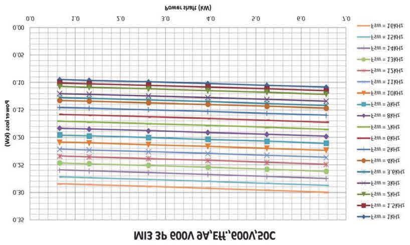
16 * Min clearance A and B for drives for MI1 ~ MI3 can be 0 inches if the ambient temperature is below 104 F (40 C). NOTE: a. = clearance around the freq. converter (see also b) b. = distance from one frequency converter to another or distance to cabinet wall c. = free space above the frequency converter d. = free space underneath the frequency converter See the mounting dimensions on the back of the drive. Leave free space for cooling above (3.9 in), below (2 in), and on the sides (.8 in) of SmartVFD HVAC2! (For MI1 - MI3, side-to-side installation allowed only if the ambient temperature is below 104 F (40 C); For MI4-MI5, side-to-side installation is not allowed. Table 5. Required cooling air Cooling air required Type in cfm (m³/h) MI (10) MI (10) MI (30) MI (45) MI (75) Power losses If the operator wants to raise the switching frequency of the drive for some reason (typically e.g. in order to reduce the motor noise), this inevitably affects the power losses and cooling requirements, for different motor shaft power, operator can select the switching frequency according to the graphs below


17 MI1 - MI5 3P 400 V POWER LOSS


18 MI1 - MI5 3P 230 V POWER LOSS


19 MI1 - MI3 1P 230 V POWER LOSS

20
21 EMC levels EN defines the division of frequency converters into four classes according to the level of electromagnetic disturbances emitted, the requirements of a power system network and the installation environment (see below). The EMC class of each product is defined in the type designation code. Category C1: Frequency converters of this class comply with the requirements of category C1 of the product standard EN (2004). Category C1 ensures the best EMC characteristics and it includes converters the rated voltage of which is less than 1000 V and which are intended for use in the 1st environment. NOTE: The requirements of class C are fulfilled only as far as the conducted emissions are concerned. Category C2: Frequency converters of this class comply with the requirements of category C2 of the product standard EN (2004). Category C2 includes converters in fixed installations and the rated voltage of which is less than 1000 V. The class C2 frequency converters can be used both in the 1st and the 2nd environment. Category C4: The drives of this class do not provide EMC emission protection. These kinds of drives are mounted in enclosures. Environments in product standard EN (2004) First environment: Environment that includes domestic premises. It also includes establishments directly connected without intermediate transformers to a low-voltage power supply network which supplies buildings used for domestic purposes. NOTE: Houses, apartments, commercial premises or offices in a residential building are examples of first environment locations. Second environment: Environment that includes all establishments other than those directly connected to a low-voltage power supply network which supplies buildings used for domestic purposes
 by")

22 NOTE: Industrial areas, technical areas of any building fed from a dedicated transformer are examples of second environment locations. Changing the EMC protection class from C2 to C4 The EMC protection class of MI1-3 frequency converters can be changed from class C2 to class C4 (except 115V and 600V drives) by removing the EMC-capacitor disconnecting screw, see figure below. MI4 & 5 can also be changed by removing the EMC jumpers. Fig. 16. EMC protection class, MI1 - MI3 NOTE: Do not attempt to change the EMC level back to class C2. Even if the procedure above is reversed, the frequency converter will no longer fulfil the EMC requirements of class C2! Fig. 17. EMC protection class, MI

23 Fig. 19. Jumpers Remove the main cover and locate the two jumpers. Disconnect the RFI-filters from ground by lifting the jumpers up from their default positions. See Figure Jumpers on page 23. Fig. 18. EMC protection class, MI
.")
 1~ (230V) 1~ (115V) Motor out L1 L2/N L3 R+")

24 Cabling and connections Power cabling NOTE: Tightening torque for power cables is Nm (4-5 in.lbs). 3~ (230V, 400V) Strip the plastic cable coating for 360 earthing 3~(230V, 400V, 600V) External brakeresistor 3~(230V, 400V,600V) 1~ (230V) 1~ (115V) Motor out L1 L2/N L3 R+ R- U/T1 V/T2 W/T3 1~ (230V) Motor out MAINS MOTOR BRAKE RESISTOR (NOT USED) Fig. 21. SmartVFD HVAC2 power connections, MI2 - MI3 MAINS Strip the plastic cable coating for 360 earthing MOTOR Fig. 20. SmartVFD HVAC2 power connections, MI
 Fig. 22.")
 MOTOR Fig. 23.")
25 3~ (380, 480V) Motor out 3~ (380, 480V) Motor out BRAKE MAINS RESISTOR MOTOR (NOT USED) Fig. 22. SmartVFD HVAC2 power connections, MI4 MAINS BRAKE RESISTOR (NOT USED) MOTOR Fig. 23. SmartVFD HVAC2 power connections, MI


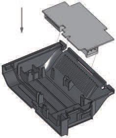
26 Control cabling Attach the support AFTER installing Attach the support AFTER installing the power cables Attach this plate BEFORE installing the power cables Attach this plate BEFORE installing the power cables Fig. 24. Mount the PE-plate and API cable support, MI1 - MI3 Fig. 25. Mount the PE-plate and API cable support, MI4 - MI

27 Fig. 26. Open the lid, MI1 - MI3 Fig. 27. Open the lid, MI4 - MI


28 Control cable tightening torque: 0.4 Nm Strip the plastic cable coating for 360 earthing Fig. 28. Install the control cables. MI1 - MI3. See Chapter Control I / O on page 53 Fig. 29. Install the control cables. MI4 - MI5. See Chapter Control I / O on page
29 Allowed option boards in SmartVFD HVAC2 NOTE: When HVFDSDOPT6DI, HVFDS- DOPT2RO1T, or HVFDSDOPT1AI2AO are used in SmartVFD HVAC2, +24VDC (±10%, min.300ma) power should be supplied to Terminal 6 (+24_out) and Terminal 3 (GND) in control board. Table 6. Option boards (all boards are varnished) HVFDSDOPT6DI/U 6 x DI/DO, each I/O can be individually HVFDSDOPT2RO1T/U 2 x Relay output + Thermistor HVFDSDOPT1AI2AO/U 1 x AI, 2 x AO (isolated) HVFDSDOPT3RO/U 3 x Relay output HVFDSDOPT1RO5DI/U 1 x RO, 5 x DI ( VAC) HVFDOPTTMP 3 x Temperature measurement (support for PT100, PT1000, NI1000, KTY84-130, KTY84-150, KTY sensors) Option board assembly structure HVFD2DOPTFR123 Option board mounting kit HVAC2 MI1-MI3 HVFD2DOPTFR45 Option board mounting kit HVAC2 MI4-MI5 Table 7. I/O Terminals on HVFDOPTTMP. Terminal Parameter reference Keypad Technical information R1.1 R1.2 R1.3 R2.1 R2.2 R2.3 R3.1 R3.2 R NC AnIn:X.1 Temperature sensor input 1, C Accuracy ±1 C AnIn:X.2 Temperature sensor input 2, C Accuracy ±1 C AnIn:X.3 Temperature sensor input 3, C Accuracy ±1 C
30 TWO-WIRE CONFIGURATION THREE-WIRE CONFIGURATION TWO-WIRE CONFIGURATION THREE-WIRE CONFIGURATION M36669 Fig. 30. HVFDOPTTMP option board wiring scheme


31 Option board mounting kit assembly
32 Screw of cables M4*8 Screws 12pcs M4*8 Screws 10pcs Fig. 33. MI3 screws M4*10 Screws 4pcs M4*9 Screws 14pcs Fig. 31. MI1 screws M4*8 Screws 10pcs M4*17 Screws 6pcs Fig. 34. MI4 - MI5 screw Fig. 32. MI2 screws
33 Cable and fuse specifications Use cables with heat resistance of at least 158 F (70 C). The cables and the fuses must be dimensioned according to the tables below. Installation of cables according to UL regulations is presented in Chapter Cable installation and the UL standards on page 38. The fuses function also as cable overload protection. The recommended fuse types are gg/gl (IEC ) or class T (UL & CSA). The fuse voltage rating should be selected according to the supply network. The final selection should be made according to local regulations, cable installation conditions and cable specification. Bigger fuses than what is recommended below should not be used. Check that the fuse operating time is less than 0.4 seconds. Operating time depends on used fuse type and impedance of the supply circuit. Consult the factory about faster fuses. Honeywell offers recommendations also for high speed J (UL & CSA ), ar (UL recognized, IEC ) and gs (IEC ) fuse ranges. These instructions apply only to cases with one motor and one cable connection from the frequency converter to the motor. In any other case, ask the factory for more information. Table 8. Cable types required to meet standards. EMC categories are described in Chapter EMC levels on page 21 EMC category cat. C2 cat. C4 Mains cable types 1 1 Motor cable types 3 1 Control cable types
34 Table 9. Cable type descriptions Cable type Description 1 Power cable intended for fixed installation and the specific mains voltage. Shielded cable not required. (NKCABLES / MCMK or similar recommended) 2 Power cable equipped with concentric protection wire and intended for the specific mains voltage. (NKCABLES / MCMK or similar recommended). 3 Power cable equipped with compact low-impedance shield and intended for the specific mains voltage. (NKCABLES / MCCMK, SAB / ÖZCUY-J or similar recommended). *360º earthing of both motor and FC connection required to meet the standard 4 Screened cable equipped with compact low-impedance shield (NKCABLES /Jamak, SAB / ÖZCuY-O or similar). Table 10. Cable and fuse sizes for SmartVFD HVAC2, 115 V, 1~ Terminal cable size (min/max) Frame Horsepower Fuse [A] Mains cable Cu [AWG] Motor cable Cu [AWG] Main terminal [AWG] Earth terminal [AWG] Control terminal [AWG] Relay terminal [AWG] MI2.33-1HP 20 2* * MI3 1.5HP 32 2* *
35 Frame Horsepower Table 11. Cable and fuse sizes for SmartVFD HVAC2, V, 1~ Fuse [A] Mains cable Cu [AWG] Motor cable Cu [AWG] Main terminal [AWG] Terminal cable size (min/max) Earth terminal [AWG] Control terminal [AWG] MI HP 10 2* * MI2 1-2HP 20 2* * MI3 3HP 32 2* * Frame Horsepower Table 12. Cable and fuse sizes for SmartVFD HVAC2, V, 3~ Fuse [A] Mains cable Cu [AWG] Motor cable Cu [AWG] Main terminal [AWG] Terminal cable size (min/max) Earth terminal [AWG] Control terminal [AWG] MI HP 6 3* * MI2 1-2HP 10 3* * MI3 3HP 20 3* * MI HP 20 3* * Cu MI HP 40 3*6+6 3* Cu / Al Relay terminal [AWG] Relay terminal [AWG]
36 Frame Horsepower Table 13. Cable and fuse sizes for SmartVFD HVAC2, V, 3~ Fuse [A] Mains cable Cu [AWG] Motor cable Cu [AWG] Main terminal [AWG] Terminal cable size (min/max) Earth terminal [AWG] Control terminal [AWG] MI1.5-1HP 6 3* * MI HP 10 3* * MI HP 20 3* * MI HP 25 3* * Cu MI HP 40 3*6+6 3* Cu / Al Relay terminal [AWG] Table 14. Cable and fuse sizes for SmartVFD HVAC2, 600 V,3~ Terminal cable size (min/max) Frame Horsepower Fuse [A] Mains cable Cu [AWG] Motor cable Cu [AWG] Main terminal [AWG] Earth terminal [AWG] Control terminal [AWG] Relay terminal [AWG] MI3 1-3HP 6 3* * MI3 5HP 10 3* * MI3 7.5HP 20 3* * NOTE: To fulfill standard EN , the protective conductor should be at least 8 AWG Cu or 6 AWG Al. Another possibility is to use an additional protective conductor of at least the same size as the original one
37 General cabling rules 1 Before starting the installation, check that none of the components of the frequency converter is live. 2 Place the motor cables sufficiently far from other cables: Avoid placing the motor cables in long parallel lines with other cables. If the motor cable runs in parallel with other cables, the minimum distance between the motor cable and other cables is 1 ft. (0.3 m.) The given distance also applies between the motor cables and signal cables of other systems. The maximum length of the motor cables for MI1-3 is 98 ft. (30 m). For MI4 & 5, maximum length is 164 ft. (50 m), if use longer cable, current accuracy will be decreased. The motor cables should cross other cables at an angle of 90 degrees. 3 If cable insulation checks are needed, see Chapter Cable and motor insulation checks on page Connecting the cables: Strip the motor and mains cables as advised in Figure Stripping of cables on page 38. Connect the mains, motor and control cables into their respective terminals, see Figures SmartVFD HVAC2 power connections, MI1 on page 24 - Install the control cables. MI4 - MI5. See Chapter Control I / O on page 53 on page 28. Note the tightening torques of power cables and control cables given in chapter Power cabling on page 24 and Control cabling on page 26. For information on cable installation according to UL regulations see Chapter Cable installation and the UL standards on page 38. Make sure that the control cable wires do not come in contact with the electronic components of the unit. Check the connection of the earth cable to the motor and the frequency converter terminals marked with Connect the separate shield of the motor cable to the earth plate of the frequency converter, motor and the supply centre
38 Stripping lengths of motor and mains cables 8 mm Earth conductor 8 mm Cable installation and the UL standards To meet the UL (Underwriters Laboratories) regulations, a UL-approved copper cable with a minimum heat-resistance of 140/167 F (60/75 C) must be used. 35 mm 20 mm Use Class 1 wire only. The units are suitable for use on a circuit capable of delivering not more than 50,000 rms symmetrical amperes, 600V maximum, when protected by T and J Class fuses. NOTE: Fig. 35. Stripping of cables Strip also the plastic cover of the cables for 360 degree earthing. See Figures SmartVFD HVAC2 power connections, MI1 on page 24, SmartVFD HVAC2 power connections, MI2 - MI3 on page 24 and Install the control cables. MI1 - MI3. See Chapter Control I / O on page 53 on page 28. Integral solid state short circuit protection does not provide branch circuit protection. Branch circuit protection must be provided in accordance with the National Electric Code and any additional local codes. Branch circuit protection provided by fuses only. Motor overload protection provided at 110% of full load current
39 Cable and motor insulation checks These checks can be performed as follows if motor or cable insulations are suspected to be faulty. 1. Motor cable insulation checks Disconnect the motor cable from terminals U / T1, V / T2 and W / T3 of the frequency converter and from the motor. Measure the insulation resistance of the motor cable between each phase conductor as well as between each phase conductor and the protective ground conductor. The insulation resistance must be >1 MOhm. 2. Mains cable insulation checks Disconnect the mains cable from terminals L1, L2 / N and L3 of the frequency converter and from the mains. Measure the insulation resistance of the mains cable between each phase conductor as well as between each phase conductor and the protective ground conductor. The insulation resistance must be >1 MOhm. 3. Motor insulation checks Disconnect the motor cable from the motor and open the bridging connections in the motor connection box. Measure the insulation resistance of each motor winding. The measurement voltage must equal at least the motor nominal voltage but not exceed 1000 V. The insulation resistance must be >1 MOhm
40 COMMISSIONING AND START-UP WIZARD Before commissioning, read the warnings and instructions listed in Safety on page 3! Commissioning steps of SmartVFD HVAC2 1 Read carefully the safety instructions in Safety on page 3 and follow them. 2 After the installation, make sure that: both the frequency converter and the motor are grounded. the mains and motor cables comply with the requirements given in Cable and fuse specifications on page 33. the control cables are located as far as possible from the power. cables (see General cabling rules on page 37, step 2) and the shields of the shielded cables are connected to protective earth. 3 Check the quality and quantity of cooling air ( Cooling on page 15). 4 Check that all Start / Stop switches connected to the I / O terminals are in Stopposition. 5 Connect the frequency converter to mains
41 6 Set the parameters of group 1 according to the requirements of your application. At least the following parameters should be set: motor nominal speed ( Quick setup parameters (Virtual menu, shows when par = 1) on page 73) motor nominal current ( Quick setup parameters (Virtual menu, shows when par = 1) on page 73) application type ( Active fire mode parameter group on page 172) You will find the values needed for the parameters on the motor rating plate. 7 Perform test run without motor. Perform either Test A or Test B: A) Control from the I / O terminals: Turn the Start/Stop switch to ON position. Change the frequency reference (potentiometer). Check the Monitoring Menu and make sure that the value of Output frequency changes according to the change of frequency reference. Turn the Start / Stop switch to OFF position. B) Control from the keypad: Select the keypad as the control place with par 2.1. You can also move to keypad control by pressing Loc / Rem button or select Local control with par 2.5. Push the Start button on the keypad. Check the Monitoring Menu and make sure that the value of Output frequency. changes according to the change of frequency reference. Push the Stop button on the keypad
42 8 Run the no-load tests without the motor being connected to the process, if possible. If this is impossible, secure the safety of each test prior to running it. Inform your coworkers of the tests. Switch off the supply voltage and wait up until the drive has stopped. Connect the motor cable to the motor and to the motor cable terminals of the frequency converter. See to that all Start / Stop switches are in Stop positions. Switch the mains ON. Repeat test 7A or 7B. 9 Perform an identification run (see Motor identification on page 128), especially if the application requires a high startup torque or a high torque with low speed. 10 Connect the motor to the process (if the noload test was running without the motor being connected). Before running the tests, make sure that this can be done safely. Inform your co-workers of the tests. Repeat test 7A or 7B. Startup Wizard Honeywell HVAC2 runs the startup wizard at initial power-up and whenever the drive is reset to factory defaults. The Start-up wizard content is shown below. It always asks the basic parameters (P1.1-P16.1). If you Activate the fire mode parameters with P16.1, it will go through rest of the Fire mode parameters. Start-Up Wizard Parameter Group P1.1 Motor Nominal Voltage P1.2 Motor Nominal Frequency P1.3 Motor Nominal Speed P1.4 Motor Nominal Current P1.5 Motor Cos phi (Power Factor) P1.7 Current Limit P1.23 Energy Optimization P3.1 Min. Frequency
43 P3.2 Max. Frequency P16.1 Active Fire Mode Parameter Group P18.1 Fire Mode Password P18.2 Fire Mode Frequency Select P18.3 Fire Mode Frequency Preset P18.4 Fire Mode Activation Close P18.5 Fire Mode Activation Open P18.6 Fire Mode Reverse FAULT TRACING When a fatal fault is detected by the frequency converter control electronics, the drive will stop and the symbol FT and the fault code blinked on the display are in the following format, e.g.: FT 2 Fault code (02 = overvoltage) The active fault can be reset by pressing BACK / RESET button when the API is in active fault menu level (FT XX), or pressing BACK / RESET button with long time (> 2 s) when the API is in active fault submenu level (F5.x ), or via the I / O terminal or field bus. Reset fault history (long push > 5 s), when the API is in fault history submenu level (F6.x). The faults with subcode and time labels are stored in the Fault history submenu which can be browsed. The different fault codes, their causes and correcting actions are presented in the table below
44 Table 15. Fault codes Fault code Fault name Possible cause Correcting actions 1 Overcurrent Frequency converter has detected too Check loading. high a current (>4*I N ) in the motor cable: Check motor size. sudden heavy load increase Check cables. short circuit in motor cables unsuitable motor 2 Overvoltage The DC-link voltage has exceeded the internal safety limit: deceleration time is too short high overvoltage peaks in mains 3 Earth fault Current measurement has detected extra leakage current at start: insulation failure in cables or motor 8 System fault component failure faulty operation Increase the deceleration time ( Deceleration time 1 on page 74 or 0,1 on page 90) Check motor cables and motor Reset the fault and restart. If the fault re-occurs, contact the distributor near to you. NOTE! If fault F8 occurs, find out the subcode of the fault from the Fault History menu under Id xxx!
45 9 Under voltage The DC-link voltage has gone below the internal safety limit: most probable cause: supply voltage is too low frequency converter internal fault Power outages In case of temporary supply voltage break reset the fault and restart the frequency converter. Check the supply voltage. If it is adequate, an internal failure has occurred. Contact the distributor near to you. 10 Input phase fault Input phase is missing Check supply voltage, fuses and cable. 11 Output phase fault Current measurement has detected that there is no current in one motor phase. 13 Frequency converter under temperature 14 Frequency converter over temperature Table 15. Fault codes Fault code Fault name Possible cause Correcting actions Heat sink temperature is under 14 F (-10 C) Heat sink is overheated. Check motor cable and motor. Check the ambient temperature. Check that the cooling air flow is not blocked. Check the ambient temperature. Clean the heatsink dust. Make sure that the switching frequency is not too high in relation to ambient temperature and motor load
46 15 Motor stalled Motor stall protection has tripped. Check that the motor is able to rotate freely. 16 Motor over temperature Motor overheating has been detected by frequency converter motor temperature model. Motor is overloaded. Decrease the motor load. If no motor overload exists, check the temperature model parameters. 17 Motor underload Motor underload protection has tripped. Check motor and load, e.g. for broken belts or dry pumps. 22 EEPROM checksum fault 25 Microcontroller watchdog fault 27 Back EMF protection Parameter save fault faulty operation component failure faulty operation component failure Table 15. Fault codes Fault code Fault name Possible cause Correcting actions Drive has detected that the magnetized motor is running in start situation. A rotating PM-motor Contact the distributor near to you. Reset the fault and restart. If the fault re-occur, contact the distributor near to you. Make sure that there is no rotating PM-motor when the start command is given
47 29 Thermistor fault The thermistor input of option board has detected increase of the motor temperature. 34 Internal bus communication Ambient interference or defective hardware. Check motor cooling and loading. Check thermistor connection (If thermistor input of the option board is not in use it has to be short circuited). If the fault re-occur, contact the distributor near to you. 35 Application fault Application is not working properly. Contact the distributor near to you. 41 IGBT Overtemperature 50 Analog input select 20% - 100% (selected signal range 4 to 20 ma or 2 to 10 V) Table 15. Fault codes Fault code Fault name Possible cause Correcting actions Overtemperature alarm is issued when the IGBT switch temperature exceeds 230 F (110 C) Current at the analogue input is < 4mA; Voltage at the analogue input is < 2 V. control cable is broken or loose. signal source has failed. 51 External fault Digital input fault. Digital input has been programmed as external fault input and this input is active. Check loading. Check motor size. Make identification run. Check the current loop circuitry. Remove the external device fault
48 52 Door Panel fault Control place is keypad, but door panel has been disconnected. 53 Fieldbus fault The data connection between the fieldbus Master and the fieldbus of the drive has broken. 54 Slot fault The connection between optional board and API has been broken. 55 Wrong run fault (FWD/REV conflict) Table 15. Fault codes Fault code Fault name Possible cause Correcting actions Run forward and backward are high at the same time. Check the connection between optional board and API. If connection is correct, contact the nearest Honeywell distributor. Check installation. If installation is correct, contact the nearest Honeywell distributor. Check board and slot. Contact the nearest Honeywell distributor. Check I/O control signal 1 and I/O control signal Idenfication fault Identification run has failed. Run command was removed before completion of identification run. Motor is not connected to frequency converter. There is load on motor shaft. 111 Temperature fault Over low or over high temperature Check temperature signal from HVFDOPTTMP board
49 Table 16. Fault subcodes from power F08 SubCode 60 Watchdog reset Fault 61 SW stack overflow 62 HW stack overflow 63 Misalignment 64 Illegal op 65 PLL lost lock / Low CPU voltage 66 EEPROM Device 67 EEPROM Queue full 68 MPI communication (dead or CRC errors) 70 CPU load 71 External oscillator 72 Fault in Power triggered by user Table 17. Fault Subcodes from control API F08 SubCode Fault 84 MPI CRC 86 MPI2 CRC 89 HMI receive buffer overflow 90 MODBUS receive buffer overflow 93 Power source cannot be recognized (triggered as alarm) 96 MPI queue full 97 MPI off line error 98 MPI driver error 99 Option Board Driver Error 100 Option Board Configure Error 104 OBI channel full 105 OBI memory allocate fail 106 OBI object queue full 107 OBI HMI queue full 108 OBI SPI queue full 111 Parameter copy error
50 Table 17. Fault Subcodes from control API F08 SubCode Fault 113 Frequency detective timer overflow 114 PC control time out error 115 Device Property data format tree too deep exceed Task stack overflow Table 18. Fault subcodes F22 SubCode Fault 1 DA_CN, Power down data counter error 2 DA_PD, Power down data restore fail 3 DA_FH, Fault history data error Table 18. Fault subcodes F22 SubCode Fault 4 DA_PA, Restore parameter CRC error 5 Reserved. 6 DA_PER_CN, Persist data counter error 7 DA_PER_PD, Persist data restore fail Table 19. Fault subcodes F35 SubCode Fault 1 Application software flash error 2 Application header error
51 SMARTVFD HVAC2 APPLICATION INTERFACE Introduction There is only one version of Control Board available for the SmartVFD HVAC2 drive: Table 20. Available Control Board Version Composition 6 Digital inputs 2 Analogue inputs 1 Analogue output 1 Digital output SmartVFD 2 Relay outputs HVAC2 RS-485 Interface This section provides you with a description of the I / O-signals for SmartVFD HVAC2 and instructions for using the SmartVFD HVAC2 general purpose application. The frequency reference can be selected from Preset Speed 0, Keypad, Fieldbus, AI1, AI2, AI1+AI2, PID, Motor potentiometer
52 BASIC PROPERTIES: Digital inputs DI1 DI6 are freely programmable. The user can assign a single input to many functions. Digital-, relay- and analogue outputs are freely programmable. Analog output can be programmed as current or voltage output. Analog input 1 can be as voltage input,analog input 2 can be programmed as current or voltage input. SPECIAL FEATURES: Programmable Start / Stop and Reverse signal logic Motor pre-heat Reference scaling DC-brake at start and stop Programmable U / f curve Adjustable switching frequency Autoreset function after fault Protections and supervisions (all fully programmable; off, alarm, fault): Analog input low fault External fault Undervoltage fault Earth fault Motor thermal, stall and underload protection Fieldbus communication Output phase fault Thermistor fault 8 preset speeds Analogue input range selection, signal scaling and filtering PID-controller
53 Control I / O Table 21. SmartVFD HVAC2 General purpose application default I / O configuration and connections for control board P) = Programmable function, see parameter lists and descriptions, STANDARD application parameters on page 72 and Parameter descriptions on page kω Terminal Signal Factory preset Description ma Vref Ref. voltage out Maximum load 10 ma 2 AI1 Analog signal in 1 Freq. reference P) 0-10 V, Ri = 250 kω 3 GND I / O signal ground 6 24 Vout 24 V output for ±20%, max. load 50 ma DI's 7 DI_C Digital Input Common 8 DI1 Digital input 1 Start forward P) Positive, 9 DI2 Digital input 2 Start reverse P) 10 DI3 Digital input 3 Fault reset P) Digital Input Common for DI1- DI6, refer to Table Table 22 on page 54 for DI sink type Logic1: 18 30V, Logic0: 0 5V; Negative, Logic1: 0 10V, Logic0: 18 30V; Ri = 10KΩ (floating) A A RS485 signal A FB Communication Negative B B RS485 signal B FB Communication Positive 4 AI2 Analog signal in 2 PID actual value and Freq. reference P) 5 GND I / O signal ground 13 DO- Digital Output Common Default: 0(4) - 20 ma, Ri 250 Ω Other: V, Ri = 250 kω Selectable through microswitch Digital Output Common 14 DI4 Digital input 4 As DI1 15 DI5 Digital input 5 As DI1, Selectable through microswitch 16 DI6 Digital input 6 As DI1 18 AO Analog Output Output frequency P) 0(4) - 20 ma, RL 500Ω 0-10 V, RL 1 KΩ Selectable through microswitch 20 DO Digital signal out Active = READY P) Open collector, max. load 35 V / 50 ma 22 RO1 NO 23 RO1 CM 24 RO2 NC 25 RO2 CM 26 RO2 NO Relay out 1 Relay out 2 Active = RUN P) Active = FAULT P) Switching load: 250 Vac / 3 A, 24V DC 3A Switching load: 250 Vac / 3 A, 24V DC 3A
54 Table 22. DI Sink Type, remove jumper J500 and connect the wire using table 6.3 Terminal Signal Factory preset Description 3 GND I / O signal ground 6 24 Vout 24 V output for DI's ±20%, max. load 50 ma 7 DI_C Digital Input Digital Input Common for DI1-DI6 Common 8 DI1 Digital input 1 Start forward P) Positive, Logic1: V, Logic0: 0 5V; Negative, Logic1: 0 10V, Logic0: 18 30V; Ri = 10KΩ (floating) 9 DI2 Digital input 2 Start reverse P) 10 DI3 Digital input 3 Fault reset P) 14 DI4 Digital input 4 Positive, Logic1: V, Logic0: 0 5V; Negative, Logic1: 0 10V, Logic0: 18 30V; Ri = 10KΩ (floating) 15 DI5 Digital input 5 Only for DI. 16 DI6 Digital input 6 Only for DI
55 J500 S4 S3 S2 S1 ON CONTROL PANEL General DI Encoder * AO - V ma A12 - V ma OFF RS485 - Term The panel is an irremovable part of the drive consisting of corresponding control board; The overlay with display status on the cover and the button are in clarifications in the user language. The User Panel consists of an alphanumeric LCD display with backlight and a keypad with the 9 push buttons (see Figure SmartVFD HVAC2 Control panel on page 56). *Not used. Must leave at default. Fig. 36. Microswitches SmartVFD HVAC2 I / O terminals: AI2 GND DO- DI4 DI5 DI6 AO DO RO1 RO1 RO2 NO CM * NO VAI1 GND 24V DI-C DI1 DI2 DI3 A B RO2 CM RO2 NC Display The display includes 14-segment and 7-segment blocks, arrowheads and clear text unit symbols. The arrowheads, when visible, indicate some information about the drive, which is printed in clear text in user language on the overlay (numbers 1 14 in the figure below). The arrowheads are grouped in 3 groups with the following meanings and English overlay texts (see Figure SmartVFD HVAC2 Control panel on page 56):
56 Group 1-5; Drive status 1. Drive is ready to start (READY) 2. Drive is running (RUN) 3. Drive has stopped (STOP) 4. Alarm condition is active (ALARM) 5. Drive has stopped due to a fault (FAULT) Group 6-10; Control selections When API is operated by PC control, there are no arrowhead at I / O, KEYPAD and BUS. 6. Motor is rotating forward (FWD) 7. Motor is rotating reverse (REV) 8. I/O terminal block is the selected control place (I / O) 9. Keypad is the selected control place (KEY- PAD) 10. Fieldbus is the selected control place (BUS) Group 11-14; Navigation main menu STOP START 11. Reference main menu (REF) 12. Monitoring main menu (MON) 13. Parameter main menu (PAR) 14. System main menu (SYS) MCR36494 Fig. 37. SmartVFD HVAC2 Control panel
57 Keypad The keypad section of the control panel consists of 9 buttons (see Figure SmartVFD HVAC2 Control panel on page 56). The buttons and their functions are described as Table Keypad Function on page 58. The drive stops by pressing the keypad STOP button, regardless of the selected control place when Par. 2.7 (Keypad stop button) is 1. If Par. 2.7 is 0, the drive stops by keypad STOP button only when control place is keypad. The drive starts by pressing the keypad START button when the selected control place is KEYPAD or LOCAL control
58 Table 23. Keypad Function Symbol Button Name Function Description Start Motor START from the panel START STOP Motor STOP from the panel STOP OK Used for confirmation.enter edit mode for parameter. Alternate in display between the parameter value and parameter code. Reference frequency value adjusting no need to press OK-button to confirm
59 Back / Reset Table 23. Keypad Function Symbol Button Name Function Description Cancels edited parameter Move backwards in menu levels Reset fault indication Up and Down Select root parameter number on root-parameter list, Up decrease / Down increase parameter number, Up increase / Down decrease parameter value change. Left and Right Available in REF,PAR and SYS menu parameter digit setting when changing value. MON,PAR and SYS can also use left and right button to navigate the parameter group, like e.g.,in MON menu use right button from V1.x to V2.x to V3.x. Can be used to change direction in REF menu in local mode: -Right arrow would mean reverse (REV) -Left arrow would mean forward (FWD) Loc / Rem Change control place NOTE: The status of all the 9 buttons are available for application program!
60 NAVIGATION ON THE SMARTVFD HVAC2 CONTROL PANEL This chapter provides you with information on navigating the menus on SmartVFD HVAC2 and editing the values of the parameters. Main menu The menu structure of SmartVFD HVAC2 control software consists of a main menu and several submenus. Navigation in the main menu is shown below:
61 REFERENCE MENU Dispalys the keypad reference value regardless of the selected contron place. REF MON PA R SYS READY RUN STOP ALARM FAULT READY REF MON PA R Hz PRESS SYS Hz RUN STOP ALARM FAULT FWD REV I/O KEYPAD BUS FWD REV I/O KEYPAD BUS PRESS MONITORING MENU In this menu you can browse the monitoring values. REF MON PA R READY RUN STOP ALARM FAULT READY REF MON PAR RUN STO P ALARM FAULT SYS PRESS SYS FWD REV I/O KEYPAD BUS FWD REV I/O KEYPAD BUS PRESS PARAMETER MENU In this menu you can browse and edit the parameters. SYSTEM MENU Here you will be able to browse system parameter and fault submenu. REF MON PAR READY RUN STOP ALARM FAULT SYS FWD REV I/O KEYPAD BUS READY REF PRESS RUN STOP ALARM FAULT PAR PRESS SYS READY REF MON FWD REV I/O KEYPAD BUS READY REF Fig. 38. The main menu of SmartVFD HVAC2 RUN STOP ALARM FAULT RUN STO P ALARM FAU LT MON MON PAR PAR SYS PRESS SYS FWD REV I/O KEYPAD BUS FWD REV I/O KEYPAD BUS
62 Reference menu REF MON PA R SYS READY RUN STOP ALARM FAULT Hz FWD REV I/O KEYPAD BUS Press to enter edit mode Change value Move to the reference menu with the UP / DOWN button (see Figure The main menu of SmartVFD HVAC2 on page 61). The reference value can be changed with UP / DOWN button as shown in Figure Reference menu display on page 62. If the value has big change, first press Left and Right buttons to select the digit which has to be changed, then press Up button to increase and Down button to decreases the value in the selected digit. The changing reference frequency will been taken into use immediately without pressing OK. Fig. 39. Reference menu display NOTE: LEFT and RIGHT buttons can be used to change the direction in Ref menu in local control mode
63 Monitoring menu REF MON PAR SYS 1 Press OK to enter 2 Monitoring menu REF MON PAR SYS 3 REF MON PAR SYS READY RUN STOP Prsess Down to browse V4.5 ALARM FAULT REF MON PAR SYS READY RUN STOP ALARM Press Left/Right to browse other Monitoring groups 4 Preess OK the value is displayed 5 Press OK V4.5 is display Fig. 40. Monitoring menu display FAULT FWD REV I/O KEYPAD BUS FWD REV I/O KEYPAD BUS READY READY RUN RUN STOP STOP ALARM ALARM FAULT FWD REV I/O KEYPAD BUS FAULT FWD REV I/O KEYPAD BUS REF MON PAR SYS READY RUN STOP ALARM FAULT FWD REV I/O KEYPAD BUS Monitoring values are actual values of measured signals as well as status of some control settings. It is visible in SmartVFD HVAC2 display, but it can not be edited. The monitoring values are listed in Table Monitoring values on page 64. Pressing Left/Right button to change the actual parameter to the first parameter of the next group, to browse monitor menu from V1.x to V2.1 to V3.1 to V4.1. After entering the desired group, the monitoring values can be browsed by pressing UP /DOWN button, as shown in Figure Monitoring menu display on page 63. In MON menu the selected signal and its value are alternateing in the display by pressing OK button. NOTE: NOTE: Turn on drive power, arrowhead of main menu is at MON, V x.x or monitor parameter value of Vx.x is displayed in Panel. Display Vx.x or monitor parameter value of Vx.x is determined by the last show status before power shut down. E.g., it was V4.5, and it is also V4.5 when restart
64 Table 24. Monitoring values Code Monitoring signal Unit ID Description V1.1 Output frequency Hz 1 Output frequency to motor V1.2 Frequency reference Hz 25 Frequency reference to motor control V1.3 Motor speed rpm 2 Calculated motor speed V1.4 Motor current A 3 Measured motor current V1.5 Motor torque % 4 Calculated actual / nominal torque of the motor V1.6 Motor shaft power % 5 Calculated actual / nominal power of the motor V1.7 Motor voltage V 6 Motor voltage V1.8 DC-link voltage V 7 Measured DC-link voltage V1.9 Unit temperature C 8 Heatsink temperature V1.10 Motor temperature % 9 Calculated motor temperature V1.11 Output Power KW 79 Output power from drive to motor V2.1 Analog input 1 % 59 AI1 signal range in percent of used range V2.2 Analog input 2 % 60 AI2 signal range in percent of used range V2.3 Analog output % 81 AO signal range in percent of used range V2.4 Digital input status DI1, 15 Digital input status DI2, DI3 V2.5 Digital input status DI4, DI5, DI6 16 Digital input status
65 Table 24. Monitoring values Code Monitoring signal Unit ID Description V2.6 RO1, RO2, DO 17 Relay / digital output status V2.11 Analog input E1 % 61 Analogue input signal 1 in % from option board, hidden until an option board is connected V2.12 Analog output E1 % 31 Analogue output signal 1 in % from option board, hidden until an option board is connected V2.13 Analog output E2 % 32 Analogue output signal 2 in % from option board, hidden until an option board is connected V2.14 DIE1, DIE2, DIE3 33 This monitor value shows status of the digital inputs 1-3 from option board, hidden until an option board is connected V2.15 DIE4, DIE5, DIE6 34 This monitor value shows status of the digital inputs 4-6 from option board, hidden until an option board is connected V2.16 DOE1, DOE2, DOE3 35 This monitor value shows status of the relay outputs 1-3 from option board, hidden until an option board is connected V2.17 DOE4, DOE5, DOE6 36 This monitor value shows status of the relay outputs 4-6 from option board, hidden until an option board is connected V2.18 Temperature input 1 50 Measured value of Temperature input 1 in temperature unit (Celsius or Kelvins) by parameter setting, hidden until an option board is connected
66 Table 24. Monitoring values Code Monitoring signal Unit ID Description V2.19 Temperature input 2 51 Measured value of Temperature input 2 in temperature unit (Celsius or Kelvins) by parameter setting, hidden until an option board is connected V2.20 Temperature input 3 52 Measured value of Temperature input 3 in temperature unit (Celsius or Kelvins) by parameter setting, hidden until an option board is connected V3.1 Drive status word 43 Bit codes status of drive B0 = Ready B1 = Run B2 = Reverse B3 = Fault B6 = RunEnable B7 = AlarmActive B12 = RunRequest B13 = MotorRegulatorActive V3.2 Application status word 89 Bit codes status of application: B3 = Ramp 2 Active B5 = Remote CTRL Place 1 active B6 = Remote CTRL Place 2 active B7 = Fieldbus Control Active B8 = Local Control Active B9 = PC Control Active B10 = Preset Frequencies Active
67 Table 24. Monitoring values Code Monitoring signal Unit ID Description V3.3 DIN status word 56 B0 = DI1 B1 = DI2 B2 = DI3 B3 = DI4 B4 = DI5 B5 = DI6 B6 = DIE1 B7 = DIE2 B8 = DIE3 B9 = DIE4 B10 = DIE5 B11 = DIE6 V4.1 PID setpoint % 20 Regulator setpoint V4.2 PID feedback value % 21 Regulator actual value V4.3 PID error % 22 Regulator error V4.4 PID output % 23 Regulator output
68 Table 24. Monitoring values Code Monitoring signal Unit ID Description V4.5 Process 29 Scaled process variable see P14.18 on page 111 V5.1 Fire mode status = Disabled 1 = Enabled 2 = Activated (Enabled + DI Open) 3 = Test Mode V5.2 Fire mode counter 1679 Fire mode counter tells how many times fire mode has been activated. This counter can not be reset. V5.3 Warranty affected device = Device is warranty affected as critical faults triggered in fire mode 0 = Normal device Parameter menu In Parameter menu only the Quick setup parameter list is shown as default. By giving the value 0 to the parameter 17.2, it is possible to open other advanced parameter groups. The parameter lists and descriptions can be found in STANDARD application parameters on page 72 and Parameter descriptions on page 124. The following figure shows the parameter menu view:
69 REF MON PA R SYS REF MON PA R SYS READY RUN STOP ALARM FAULT REF MON PA R SYS READY STOP ALARM FAULT FWD REV I/O KEYPAD BUS FWD REV I/O KEYPAD BUS 1 Press OK to enter Pa r. menu READY RUN STOP ALARM FAULT FWD REV I/O KEYPAD BUS REF MON PA R SYS 2 Press Right to browse otherpar. group READY RUN RUN STOP ALARM FAULT FWD REV I/O KEYPAD BUS Left / Right button is available inside Parameter menu. Pressing Left / Right button to change the actual parameter to the first parameter of the next group (Example: any parameter of P1 is displayed -> RIGHT button -> P2.1 is displayed -> RIGHT button -> P3.1 is displayed ). After entering the desired group, pressing UP / DOWN button to select root parameter number, and then press OK button to display the value of the parameter and also enter edit mode. In edit mode, Left and Right buttons are used to select the digit which has to be changed, and Up increases / Down decreases parameter value. 3 Press down button to browse P3.4 REF MON PA R SYS READY RUN STOP Hz ALARM FAULT FWD REV I/O KEYPAD BUS 4 Press OK button to enter edit mode 6 Press OK to confirm In edit mode, the value of Px.x is displayed blinkingly in the panel. After about 10 s, Px.x is displayed in the panel again if you don't press any button. NOTE: In edit mode, if you edit the value and don't press OK button, the value isn't changed successfully. 5 Press Up / Down to change value Fig. 41. Parameter menu The parameter can be changed as the Figure Parameter menu on page 69. NOTE: In edit mode, if you don't edit the value, you can press Reset /Back button to display Px.x again
70 System menu SYS menu including fault submenu, field bus submenu and system parameter submenu, and the display and operation of the system parameter submenu is similar to PAR menu or MON menu.in system parameter submenu, there are some editable parameter (P) and some uneditable parameter (V). The Fault submenu of SYS menu includes active fault submenu and fault history submenu. READY RUN STOP ALARM FAULT REF MON PAR SYS FWD REV I/O KEYPAD BUS 1 Press OK to enter V1.1 READY RUN STOP ALARM FAULT REF MON PAR SYS FWD REV I/O KEYPAD BUS REF MON PAR SYS READY 2 RUN STOP ALARM FAULT FWD REV I/O KEYPAD BUS Press Left/Right button to browse other groups READY RUN STOP ALARM FAULT REF MON PAR SYS FWD REV I/O KEYPAD BUS 3 READY REF MON PAR SYS Pressdowntobrowse other active faults RUN STOP ALARM FAULT FWD REV I/O KEYPAD BUS 4 5 Press OK to select one fault to browse its time Browse for fault code(c xx), subcode(id xx), days(d xx), hours(h xx), minutes(m xx) Fig. 42. Fault menu In active fault situation, FAULT arrow is blinking and the display is blinking active fault menu item with fault code. If there are several active faults, you can check it by entering the active fault submenu F5.x. F5.1 is always the latest active fault code. The active faults can be reset by
71 pressing BACK / RESET button with long time (>2 s), when the API is in active fault submenu level (F5.x). If the fault cannot be reset, the blinking continues. It is possible to select other display menus during active fault, but in this case the display returns automatically to the fault menu if no button is pressed in 10 seconds. The fault code, subcode and the operating day, hour and minute values at the fault instant are shown in the value menu (operating hours = displayed reading). NOTE: Fault History can be reset by long pressing the BACK / RESET button for 5 second time,when the API is in fault history submenu level (F6.x), it will also clear all active faults
72 STANDARD APPLICATION PARAMETERS On the next pages you can find the lists of parameters within the respective parameter groups. The parameter descriptions are given in Parameter descriptions on page 124. Explanations: Code: Parameter: Min: Max: Unit: Default: ID: i Location indication on the keypad; Shows the operator the present Monitoring value number or Parameter number Name of monitoring value or parameter Minimum value of parameter Maximum value of parameter Unit of parameter value; given if available Factory preset value ID number of the parameter (used with fieldbus control) More information on this parameter available in Parameter descriptions on page 124. Click on the parameter name. Modifiable only in stop state
73 Quick setup parameters (Virtual menu, shows when par = 1) i i Table 25. Quick setup parameters. Code Parameter Min Max Unit Default ID Note P1.1 Motor nominal V Varies 110 voltage P1.2 Motor nominal frequency 30,00 320,00 Hz 50,00 /60, P1.3 Motor nominal speed P1.4 Motor nominal current rpm 1440 /1720 0,2 x I Nunit 2,0 x I Nunit 112 A I Nunit 113 A P1.5 Motor cos ϕ 0,30 1,00 0, (Power Factor) P1.7 Current limit 0,2 x 2,0 x 1,5 x 107 I Nunit I Nunit INunit P1.15 Torque boost P1.23 Energy optimization Energy optimization, the frequency converter search for the minimum current in order to save energy and lower motor noise
74 i i i i i i i i Table 25. Quick setup parameters. (Continued) Code Parameter Min Max Unit Default ID Note P2.1 Remote control place 1 selection P2.2 Start function P2.3 Stop function P3.1 Min frequency 0,00 P3.2 Hz 0, P3.2 Max frequency P ,00 Hz 50,00 /60, P3.3 Remote control 1 Varies place 1 frequency reference selection P3.4 Preset speed 0 P3.1 P3.2 Hz 5, P3.5 Preset speed 1 P3.1 P3.2 Hz 10, P3.6 Preset speed 2 P3.1 P3.2 Hz 15, P3.7 Preset speed 3 P3.1 P3.2 Hz 20, P4.2 Acceleration 0,1 3000,0 s 3,0 103 time 1 P4.3 Deceleration time 1 0,1 3000,0 s 3,
75 i P6.1 AI1 range P6.5 AI2 range (see the P6.1) P10.1 Prohibit 0,00 P3.2 Hz 0, frequency range 1 low limit P10.2 Prohibit 0,00 P3.2 Hz 0, frequency range 1 high limit P13.1 Automatic reset P14.1 Setpoint source selection Table 25. Quick setup parameters. (Continued) Code Parameter Min Max Unit Default ID Note 0 Varies = Fixed setpoint % 1 = AI1 2 = AI2 3 = ProcessDataIn1(0-100%) 4 = ProcessDataIn2(0-100%) 5 = ProcessDataIn3(0-100%) 6 = ProcessDataIn4(0-100%) 7 = AIE1 8 = Temperature input 1 9 = Temperature input 2 10 = Temperature input 3 P14.2 Fixed setpoint 1 0,0 100,0 % 50,0 167 Fixed setpoint
76 Table 25. Quick setup parameters. (Continued) Code Parameter Min Max Unit Default ID Note P14.3 Fixed setpoint 2 0,0 100,0 % 50,0 168 Alternative fixed setpoint, selectable with DI P14.4 Feedback source selection P14.5 Feedback value min P14.6 Feedback value max P14.11 Sleep min frequency 0 Varies = AI1 1 = AI2 2 = ProcessDataIn1(0-100%) 3 = ProcessDataIn2(0-100%) 4 = ProcessDataIn3(0-100%) 5 = ProcessDataIn4(0-100%) 6 = AI2-AI1 7 = AIE1 8 = Temperature input 1 9 = Temperature input 2 10 = Temperature input 3 0,0 50,0 % 0,0 336 Value at minimum signal 10,0 300,0 % 100,0 337 Value at maximum signal 0,00 P3.2 Hz 25, Threshold for enter sleep P14.12 Sleep delay s Delay for enter sleep P14.13 Wake up level 0,0 100,0 % 90, Threshold for exit sleep
77 P14.14 Sleep setpoint boost P14.15 Setpoint boost time P16.2 Parameter conceal P18.1 Fire mode password P18.2 Fire mode frequency select Table 25. Quick setup parameters. (Continued) Code Parameter Min Max Unit Default ID Note 0,0 50,0 % 10, Referred to setpoint 0 60 s Boost time after P Hides all parameters not in quick start 0 = All parameters visible 1 = Only quick setup parameter group visible = Test mode 1001 = Enable 1515 = Disable 0 Varies Fire mode frequency preset NOTE! This parameter will be locked when fire mode is active. To change the parameter you have to disable fire mode
78 P18.3 Fire mode frequency preset P18.4 Fire mode activation close P18.5 Fire mode activation open Table 25. Quick setup parameters. (Continued) Code Parameter Min Max Unit Default ID Note P3.1 P3.2 Hz Fire mode frequency preset NOTE! This parameter will be locked when fire mode is active. To change the parameter you have to disable fire mode. 0 Varies Digital input normal close As parameter 5.1 NOTE! This parameter will be locked when fire mode is active. To change the parameter you have to disable fire mode. 0 Varies Digital input normal open As parameter 5.1 NOTE! This parameter will be locked when fire mode is active. To change the parameter you have to disable fire mode
79 P18.6 Fire mode reverse Table 25. Quick setup parameters. (Continued) Code Parameter Min Max Unit Default ID Note 0 Varies Reverse command of rotation direction while running in fire mode. This DI has no effect in normal operation. As parameter 5.1 NOTE! This parameter will be locked when fire mode is active. To change the parameter you have to disable fire mode
80 Motor settings (Control panel: Menu PAR -> P1) i i i Table 26. Motor settings. Code Parameter Min Max Unit Default ID Note P1.1 Motor nominal voltage P1.2 Motor nominal frequency P1.3 Motor nominal speed P1.4 Motor nominal current V Varies ,00 320,00 Hz 50,00 /60, rpm 1440 /1720 0,2 x I Nunit 2,0 x I Nunit A I Nunit 113 P1.5 Motor cosϕ 0,30 1,00 0, (Power Factor) P1.6 Motor type = Induction 1 = Permanent magnet P1.7 Current limit 0,2 x I Nunit 2,0 x A 1,5 x 10⁷ I Nunit I Nunit P1.8 Motor control mode = Frequency control 1 = Open loop speed control P1.9 U / f ratio = Linear 1 = Square 2 = Programmable
81 i i i i i i i i P1.10 Field weakening point P1.11 Field weakening point voltage P1.12 U / f mid point frequency P1.13 U / f mid point voltage 8,00 320,00 Hz 50,00 /60, ,00 200,00 % 100, ,00 P1.10 Hz 50,00 /60, ,00 P1.11 % 100, P1.14 Zero freq voltage 0,00 40,00 % Varies 606 P1.15 Torque Boost = Disabled 1 = Enabled P1.16 Switching frequency Table 26. Motor settings. (Continued) Code Parameter Min Max Unit Default ID Note 1,5 16,0 khz 4,0 / 2,0 601 P1.17 Motor identification = not active 1 = standstill identification (need run command within 20s to activate) 2 = ID with run
82 i i P1.18 Rs voltage drop 0,00 100,00 % 0, Voltage drop over motor windings as % of Un at nominal current. This parameter is adjusted automatically when Identification run is performed. P1.19 Overvoltage controller P1.20 Undervoltage controller Table 26. Motor settings. (Continued) Code Parameter Min Max Unit Default ID Note = Disabled 1 = Enabled: default mode 2 = Enabled: shock load mode = Disable 1 = Enabled P1.21 Sine filter = Not in use 1 = In use
83 i P1.22 Modulator type feature not used, leave at default Table 26. Motor settings. (Continued) Code Parameter Min Max Unit Default ID Note Bit 1 = Discontinuous modulation Bit 2 = Pulse dropping in over modulation Bit 6 = Under modulation Bit 8 = Instantaneous DC voltage compensation Bit 11 = Low noise Bit 12 = Dead time compensation Bit 13 = Flex error compensation P1.23 Energy optimization Energy optimization, the frequency converter search for the minimum current in order to save energy and lower motor noise: 0 = Disabled 1 = Enable
84 i i i P1.24 I/f start enable The I/f Start function is typically used with permanent magnet motors (PM) to start the motor with constant current control. This is useful with high power motors in which the resistance is low and the tuning of the U/f curve difficult. Applying the I/f Start function may also prove useful in providing sufficient torque for the motor at startup. 0 = Disabled 1 = Enable P1.25 I/f start frequency reference limit P1.26 I/f start current reference Table 26. Motor settings. (Continued) Code Parameter Min Max Unit Default ID Note % Output frequency limit below which the defined I/f start current is fed to motor % The current fed to the motor when the I/f start function is activated
85 i P1.27 Voltage limiter enable Table 26. Motor settings. (Continued) Code Parameter Min Max Unit Default ID Note Voltage limiter function addresses problem with very high DC-link voltage ripple with 1-phase drives when fully loaded. Very high ripple in DC link voltage will transform to high current and torque ripple, which can disturb some users. Voltage limiter function limits maximum output voltage to bottom of DC-voltage ripple. This reduces current and torque ripple, but decreases maximum output power since voltage is limited and more current is needed. 0 = Disabled 1 = Enabled NOTE: These parameters are shown, when P16.2 =
86 i i i i i Start / stop setup (Control panel: Menu PAR -> P2) Table 27. Start / stop setup. Code Parameter Min Max Unit Default ID Note P2.1 Remote Control Place 1 Selection = I / O terminals 1 = Fieldbus 2 = Keypad P2.2 Start function = Ramping 1 = Flying start P2.3 Stop function = Coasting 1 = Ramping P2.4 I / O Start / Stop logic I / O control I / O control signal 1 signal 2 0 Forward Reverse 1 Fwd(edge) Inverted Stop 2 Fwd(edge) Bwd(edge) 3 Start Reverse 4 Start(edge) Reverse P2.5 Local / Remote = Remote control 1 = Local control
87 P2.6 Keypad control direction = Forward 1 = Backward P2.7 Keypad stop button = Keypad control only 1 = Always P2.8 Remote Control Place 2 Selection Table 27. Start / stop setup. Code Parameter Min Max Unit Default ID Note = I / O terminals 1 = Fieldbus 2 = Keypad P2.9 keypad button lock = unlock all keypad button 1 = Loc/Rem button locked
88 Frequency references (Control panel: Menu PAR -> P3) i i i i i i Table 28. Frequency references. Code Parameter Min Max Unit Default ID Note P3.1 Min frequency 0,00 P3.2 Hz 0, P3.2 Max frequency P ,00 Hz 50,00 /60,00 P3.3 Remote Control Place 1 frequency reference selection Varies = Preset speed 0 2 = Keypad 3 = Fieldbus 4 = AI1 5 = AI2 6 = PID 7 = AI1+ AI2 8 = Motor potentiometer 9 = AIE1 10 = Temperature input 1 11 = Temperature input 2 12 = Temperature input 3 P3.4 Preset speed 0 P3.1 P3.2 Hz 5, P3.5 Preset speed 1 P3.1 P3.2 Hz 10, P3.6 Preset speed 2 P3.1 P3.2 Hz 15, P3.7 Preset speed 3 P3.1 P3.2 Hz 20, P3.8 Preset speed 4 P3.1 P3.2 Hz 25,
89 i i i i Table 28. Frequency references. Code Parameter Min Max Unit Default ID Note P3.9 Preset speed 5 P3.1 P3.2 Hz 30, P3.10 Preset speed 6 P3.1 P3.2 Hz 40, P3.11 Preset speed 7 P3.1 P3.2 Hz 50, P3.12 Remote Control Place 1 Varies As parameter P3.3 2 frequency reference selection P3.13 Motor 1 50 Hz/s Potentionmeter Ramp P3.14 Motor Potentionmeter Reset = No reset 1 = Reset if stopped 2 = Reset if powered down NOTE: These parameters are shown, when P16.2 =
90 Ramps and brakes setup (Control panel: Menu PAR -> P4) i i i i i i Table 29. Ramps and brakes setup. Code Parameter Min Max Unit Default ID Note P4.1 Ramp S-shape 1 0,0 10,0 s 0,0 500 P4.2 Acceleration time 1 0,1 3000,0 s 3,0 103 P4.3 Deceleration time 1 0,1 3000,0 s 3,0 104 P4.4 Ramp S-shape 2 0,0 10,0 s 0,0 501 P4.5 Acceleration time 2 0,1 3000,0 s 10,0 502 P4.6 Deceleration time 2 0,1 3000,0 s 10,0 503 P4.7 Flux Braking = Off 1 = Deceleration 2 = Chopper 3 = Full mode P4.8 Flux Braking Current 0,5 x I Nunit 2,0 x I Nunit A I Nunit 519 P4.9 DC Braking Current 0,3 x I Nunit 2,0 x I Nunit A I Nunit 507 P4.10 Stop DC current time 0,00 600,00 s 0, = Not active P4.11 Stop DC current frequency 0,10 10,00 Hz 1, P4.12 Start DC current time 0,00 600,00 s 0, P4.13 Accel2 Frequency Threshold 0.00 P3.2 Hz 0, ,00 = Disabled P4.14 Decel2 Frequency Threshold 0,00 P3.2 Hz 0, ,00 = Disabled
91 i P4.15 External Brake: Open Delay 0,00 320,00 s 0, P4.16 External Brake: Open Frequency limit P4.17 External Brake : Close Frequency limit P4.18 External Brake : Close Frequency limit in Reverse P4.19 External Brake : Open/Close Current limit Table 29. Ramps and brakes setup. Code Parameter Min Max Unit Default ID Note 0,00 P3.2 Hz 1, ,00 P3.2 Hz 1, ,00 P3.2 Hz 1, ,0 200,0 % 20,
92 Digital inputs (Control panel: Menu PAR -> P5) i i Table 30. Digital inputs. Code Parameter Min Max Unit Default ID Note P5.1 I / O control signal 1 0 Varies = Not used 1 = DI1 2 = DI2 3 = DI3 4 = DI4 5 = DI5 6 = DI6 7 = DIE1 8 = DIE2 9 = DIE3 10 = DIE4 11 = DIE5 12 = DIE6 P5.2 I / O control signal 2 0 Varies P5.3 Reverse 0 Varies P5.4 Ext. fault Close 0 Varies P5.5 Ext. fault Open 0 Varies P5.6 Fault reset 0 Varies P5.7 Run enable 0 Varies P5.8 Preset speed B0 0 Varies
93 i i i Table 30. Digital inputs. (Continued) Code Parameter Min Max Unit Default ID Note P5.9 Preset speed B1 0 Varies P5.10 Preset speed B2 0 Varies P5.11 Ramp time 2 selection 0 Varies P5.12 Motor potentiometer up 0 Varies P5.13 Motor potentiometer down 0 Varies P5.14 Remote control place 2 0 Varies P5.15 Remote control plece freq 0 Varies reference 2 P5.16 PID setpoint 2 0 Varies P5.17 Motor PreHeat ON 0 Varies
94 Analogue inputs (Control panel: Menu PAR -> P6) i i Table 31. Analogue inputs. Code Parameter Min Max Unit Default ID Note P6.1 AI1 range = 0-100% 1 = 20% - 100% P6.2 AI1 Custom min -100,00 100,00 % 0, P6.3 AI1 Custom max -100,00 300,00 % 100, P6.4 AI1 filter time 0,0 10,0 s 0,1 378 P6.5 AI2 range As parameter P6.1 P6.6 AI2 Custom min -100,00 100,00 % 0, As parameter P6.2 P6.7 AI2 Custom max -100,00 300,00 % 100, As parameter P6.3 P6.8 AI2 filter time 0,0 10,0 s 0,1 389 As parameter P6.4 P6.9 AIE1 range As parameter P6.1, hidden until an option board is connected. P6.10 AIE1 Custom Min -100,00 100,00 % 0, As parameter P6.2, hidden until an option board is connected. P6.11 AIE1 Custom Max -100,00 300,00 % 100, As parameter P6.3, hidden until an option board is connected. P6.12 AIE1 Filter time 0,0 10,0 s 0,1 142 As parameter P6.4, hidden until an option board is connected
95 Digital outputs (Control panel: Menu PAR -> P7) Table 32. Digital outputs. Code Parameter Min Max Unit Default ID Selections P7.1 RO1 signal selection 0 Varies = Not used 1 = Ready 2 = Run 3 = Fault 4 = Fault Inverted 5 = Warning 6 = Reversed 7 = At Speed 8 = Motor regulator active 9 = FB Control Word.B13 10 = FB Control Word.B14 11 = FB Control Word.B15 12 = Output freq superv. 13 = Output torque superv. 14 = Unit temperature superv. 15 = Analogue input superv. 16 = Preset Speed Active 17 = External Brake ctrl 18 = Keypad control active 19 = I / O control active 20 = Temperature supervision P7.2 RO2 signal selcetion 0 Varies As parameter
96 Table 32. Digital outputs. (Continued) i Code Parameter Min Max Unit Default ID Selections P7.3 DO1 signal selcetion 0 Varies As parameter 7.1 P7.4 RO2 inversion = No inversion 1 = Inverted P7.5 RO2 ON delay 0,00 320,00 s 0, P7.6 RO2 OFF delay 0,00 320,00 s 0, P7.7 RO1 inversion = No inversion 1 = Inverted P7.8 RO1 ON delay 0,00 320,00 s 0, P7.9 RO1 OFF delay 0,00 320,00 s 0, P7.10 DOE1 signal selection 0 Varies As parameter 7.1, hidden until an option board is connected. P7.11 DOE2 signal selection 0 Varies As parameter 7.1, hidden until an option board is connected. P7.12 DOE3 signal selection 0 Varies As parameter 7.1, hidden until an option board is connected. P7.13 DOE4 signal selection 0 Varies As parameter 7.1, hidden until an option board is connected. P7.14 DOE5 signal selection 0 Varies As parameter 7.1, hidden until an option board is connected. P7.15 DOE6 signal selection 0 Varies As parameter 7.1, hidden until an option board is connected
97 Analogue outputs (Control panel: Menu PAR -> P8) i Table 33. Analogue outputs. Code Parameter Min Max Unit Default ID Selections P8.1 Analog output signal selection = Not used 1 = Output freq. (0-f max ) 2 = Output current (0-I nmotor ) 3 = Motor torque (0-T nmotor ) 4 = PID output (0-100%) 5 = Freq. refer. (0-f max ) 6 = Motor speed (0-n max ) 7 = Motor power (0-P nmotor ) 8 = Motor Voltage (0-U nmotor ) 9 = DC-link Voltage ( V) 10 = Process Data In1 ( ) 11 = Process Data In2 ( ) 12 = Process Data In3 ( ) 13 = Process Data In4 ( ) 14 = Test 100%
98 i Table 33. Analogue outputs. (Continued) Code Parameter Min Max Unit Default ID Selections P8.2 Analog output minimum = 0 ma 1 = 4 ma P8.3 Analog output scaling 0,0 1000,0 % 100,0 311 P8.4 Analog output filter time 0,00 10,00 s 0, P8.5 Analog output E1 signal selection P8.6 Analog output E1 minimum P8.7 Analog output E1 scaling P8.8 Analog output E1 filter time P8.9 Analog output E2 signal selection P8.10 Analog output E2 minimum P8.11 Analog output E2 scaling P8.12 Analog output E2 filter time As parameter P8.1, hidden until an option board is connected As parameter P8.2, hidden until an option board is connected. 0,0 1000,0 % 100,0 476 As parameter P8.3, hidden until an option board is connected. 0,00 10,00 s 0, As parameter P8.4, hidden until an option board is connected As parameter P8.1, hidden until an option board is connected As parameter P8.2, hidden until an option board is connected. 0,0 1000,0 % 100,0 483 As parameter P8.3, hidden until an option board is connected. 0,00 10,00 s 0, As parameter P8.4, hidden until an option board is connected
99 Fieldbus Data-Mapping (Control panel: Menu PAR -> P9) i Table 34. Fieldbus Data-Mapping. Code Parameter Min Max Unit Default ID Note P9.1 FB Data Output 1 selection P9.2 FB Data Output 2 selection P9.3 FB Data Output 3 selection P9.4 FB Data Output 4 selection 0 Varies = Frequency reference 1 = Output reference 2 = Motor speed 3 = Motor current 4 = Motor voltage 5 = Motor torque 6 = Motor power 7 = DC link voltage 8 = Active fault code 9 = AI1 10 = AI2 11 = Digital input state 12 = PID feedback value 13 = PID setpoint 14 = AIE1 0 Varies Varies Varies
100 i P9.5 FB Data Output 5 selection P9.6 FB Data Output 6 selection P9.7 FB Data Output 7 selection P9.8 FB Data Output 8 selection P9.9 Aux CW Data In selection Table 34. Fieldbus Data-Mapping. Code Parameter Min Max Unit Default ID Note 0 Varies Varies Varies Varies = Not used 1 = PDI1 2 = PDI2 3 = PDI3 4 = PDI4 5 = PDI
101 Prohibited Frequencies (Control panel: Menu PAR -> P10) i Table 35. Prohibited Frequencies. Code Parameter Min Max Unit Default ID Note P10.1 Prohibit Frequency Range 1 Low Limit 0,00 P3.2 Hz 0, P10.2 Prohibit Frequency Range 1 High Limit 0,00 P3.2 Hz 0, P10.3 Prohibit Frequency Range 2 Low Limit 0,00 P3.2 Hz 0, P10.4 Prohibit Frequency Range 2 High Limit 0,00 P3.2 Hz 0,
102 Limit Supervisions (Control panel: Menu PAR -> P11) Table 36. Limit Supervisions. Code Parameter Min Max Unit Default ID Note P11.1 Output freq. supervision function P11.2 Output freq. supervision limit P11.3 Torque supervision function P11.4 Torque supervision limit P11.5 Unit Temperature Supervision P11.6 Unit Temperature Supervision Limit P11.7 Analogue input superv signal = Not used 1 = Low limit 2 = High limit 0,00 P3.2 Hz 0, = Not used 1 = Low limit 2 = High limit 0,0 300,0 % 0, C Varies = AI1 1 = AI2 2 = AIE1 P11.8 AI superv ON level 0,00 100,00 % 80,
103 P11.9 AI superv OFF level 0,00 100,00 % 40, P11.10 Temperature supervision input P11.11 Temperature supervision function P11.12 Temperature supervision limit Table 36. Limit Supervisions. Code Parameter Min Max Unit Default ID Note Binary-coded selection of signals to use for temperature supervision B0 = Temperature input 1 B1 = Temperature input 2 B2 = Temperature input 3 NOTE! Hidden until an option board is connected As parameter 11.1, hidden until an option board is connected. -50,0/223,2 200,0/473,2 80, Temperature supervision threshold, hidden until an option board is connected
104 Protections (Control panel: Menu PAR -> P12) i i i Table 37. Protections. Code Parameter Min Max Unit Default ID Note P12.1 Analog Input low fault = No action 1 = Alarm 2 = Alarm, preset alarm frequency 3 = Fault: Stop function 4 = Fault: Coast P12.2 Under voltage fault = No response (no fault generated but drive still stops modulation) 2 = Fault: Coast P12.3 Earth fault = No action 1 = Alarm 2 = Fault: Stop function 3 = Fault: Coast P12.4 Output Phase Fault As parameter 12.3 P12.5 Stall protection As parameter 12.3 P12.6 Under load As parameter 12.3 protection P12.7 Motor thermal protection As parameter
105 i i i i i i i Table 37. Protections. (Continued) Code Parameter Min Max Unit Default ID Note P12.8 Mtp:Ambient temperature P12.9 Mtp:Zero speed cooling P12.10 Mtp:Thermal time constant C ,0 150,0 % 40, min Varies 707 P12.11 Stall Current 0,00 2,0 x I Nunit A I Nunit 710 P12.12 Stall time 0,00 300,00 s 15, P12.13 Stall frequency 0,10 320,00 Hz 25, P12.14 UL:Field weakening load 10,0 150,0 % 50,0 714 P12.15 UL:Zero freq load 5,0 150,0 % 10,0 715 P12.16 UL:Time limit 1,0 300,0 s 20,0 716 P12.17 Analog Input low fault delay 0,0 10,0 s 0, P12.18 External fault As parameter 12.3 P12.19 Fieldbus fault As parameter 12.1 P12.20 Preset alarm frequency P3.1 P3.2 Hz 25,
106 P12.21 Parameters edit lock = Edit enabled 1 = Edit disabled P12.22 Thermistor Fault Hidden until option board supporting thermistor is connected: 0 = No action 1 = Alarm 2 = Fault: Stop function 3 = Fault: Coast P12.23 FWD/REV conflict As parameter 12.3 supervision P12.24 Temperature fault As parameter P12.3, hidden until an HVFDOPTTMP board is connected. P12.25 Temperature fault input Table 37. Protections. (Continued) Code Parameter Min Max Unit Default ID Note Binary-coded selection of signals to use for alarm and fault triggering B0 = Temperature input 1 B1 = Temperature input 2 B2 = Temperature input 3 NOTE! Hidden until an HVFDOPTTMP board is connected
107 i i P12.26 Temperature fault mode P12.27 Temperature fault limit = Not used 1 = Low limit 2 = High limit -50.0C/ 273.2K" 200,0/ 473,2 100,0 742 Temperature fault threshold, hidden until an HVFDOPTTMP board is connected/ P12.28 Input phase fault = No action 1 = Alarm 2 = Fault: Stop function 3 = Fault: Coast P12.29 Motor temperature memory mode Table 37. Protections. (Continued) Code Parameter Min Max Unit Default ID Note = Disabled 1 = Constant mode 2 = Last value mode NOTE: These parameters are shown, when P16.2 =
108 Fault autoreset parameters (Control panel: Menu PAR -> P13) i i Table 38. Fault autoreset parameters Code Parameter Min Max Unit Default ID Note P13.1 Automatic Reset = Disabled 1 = Enable P13.2 Wait time 0,10 10,00 s 0, P13.3 Trial time 0,00 60,00 s 30, P13.4 Trials number P13.5 Restart Function = Ramping 1 = Flying 2 = By start function NOTE: These parameters are shown, when P16.2 =
109 PID control parameters (Control panel: Menu PAR -> P14) Table 39. PID control parameters. Code Parameter Min Max Unit Default ID Note P14.1 Setpoint source selection 0 Varies = Fixed setpoint % 1 = AI1 2 = AI2 3 = ProcessDataIn1 (0-100%) 4 = ProcessDataIn2 (0-100%) 5 = ProcessDataIn3 (0-100%) 6 = ProcessDataIn4 (0-100%) 7 = AIE1 8 = Temperature input 1 9 = Temperature input 2 10 = Temperature input 3 P14.2 Fixed setpoint 1 0,0 100,0 % 50,0 167 Fixed setpoint P14.3 Fixed setpoint 2 0,0 100,0 % 50,0 168 Alternative fixed setpoint, selectable with DI
110 i i i i P14.4 Feedback source selection P14.5 Feedback value minumum P14.6 Feedback value maximum Table 39. PID control parameters. (Continued) Code Parameter Min Max Unit Default ID Note 0 Varies = AI1 1 = AI2 2 = ProcessDataIn1 (0-100%) 3 = ProcessDataIn2 (0-100%) 4 = ProcessDataIn3 (0-100%) 5 = ProcessDataIn4 (0-100%) 6 = AI2-AI1 7 = AIE1 8 = Temperature input 1 9 = Temperature input 2 10 = Temperature input 3 0,0 50,0 % 0,0 336 Value at minimum signal 10,0 300,0 % 100,0 337 Value at maximum signal P14.7 P gain 0,0 1000,0 % 100,0 118 Proportional gain P14.8 I time 0,00 320,00 s 10, Integrative time P14.9 D time 0,00 10,00 s 0, Derivative time
111 i i i Table 39. PID control parameters. (Continued) Code Parameter Min Max Unit Default ID Note P14.10 Error inversion = Direct 1 = Inverted P14.11 Sleep minimum frequency 0,00 P3.2 Hz 25, Threshold for enter sleep P14.12 Sleep delay s Delay for enter sleep P14.13 Wake up error 0,0 100,0 % Threshold for exit sleep P14.14 Sleep setpoint 0,0 50,0 % 10, Referred to setpoint boost P14.15 Setpoint boost time 0 60 s Boost time after P14.12 P14.16 Sleep maximum loss P14.17 Sleep loss check time P14.18 Process unit source select 0,0 50,0 % 5, Referred to feedback value after boost s After boost time P = PID feedback value 1 = Output frequency 2 = Motor speed 3 = Motor torque 4 = Motor power 5 = Motor current
112 i i i P14.19 Process unit decimal digits P14.20 Process unit minimum value P14.21 Process unit maximum value P14.22 Temperature min value P14.23 Temperature max value Table 39. PID control parameters. (Continued) Code Parameter Min Max Unit Default ID Note Decimals on display 0,0 P , Process min value P ,0 100, Process max value - 50C/223.2K P C/ 473.2K P , Temperature min value for PID and frequency reference scale, hidden until an HVFDOPTTMP board is connected 100, Temperature max value for PID and frequency reference scale, hidden until an HVFDOPTTMP board is connected NOTE: These parameters are shown, when P16.2 =
113 Motor Pre-heat (Control panel: Menu PAR -> P15) Table 40. Motor Pre-heat. Index Variable name Min Max Unit Default ID Notes P15.1 PreHeat function * : not used 1: always in stop state 2: controlled by digital input 3: heatsink temperature limit 4: external temperature limit P15.2 PreHeat current 0 50% motor nominal current A Motor pre heat current P15.3 Heatsink temperature limit C Heatsink temperature to stop pre heat
114 P15.4** External temperature selection P15.5** External temperature limit Table 40. Motor Pre-heat. Index Variable name Min Max Unit Default ID Notes * value 4 only if expansion HVFDOPTTMP is installed **visible only if expansion HVFDOPTTMP is installed ***unit and values depends on P16.3 Temperature unit Selection of external temperature 0 None of the temperature inputs are selected 1 Temperature input 1 selected 2 Temperature input 2 selected 3 Temperature input 1 and 2 selected 4 Temperature input 3 selected 5 Temperature input 1 and 3 selected 6 Temperature input 2 and 3 selected 7 Temperature input 1, 2 and 3 selected -50.0*** 200.0*** C*** External temperature to stop pre heat
115 Easy usage menu (Control panel: Menu PAR -> P16) i i Table 41. Easy usage menu parameters. Code Parameter Min Max Unit Default ID Note P16.1 Active fire mode parameter group P16.2 Parameter conceal = Disable fire mode parameter group wizard 1 = Enable fire mode parameter group wizard NOTE! Visible only when Startup wizard is active = All parameters visible 1 = Only quick setup parameter group visible P16.3 Temperature unit = Celsius 1 = Kelvins NOTE! Hidden until an HVFDOPTTMP board is connected. P16.4 Application access word Input the right password could review parameter group
116 Fire mode (Control panel: Menu PAR -> P18) Drive ignores all commands from keypad, fieldbus and PC tool and preset frequency when activated. If activated, alarm sign is shown on the keypad and warranty is void. In order to enable the function, you need to set a password in the description field for parameter Fire Mode password. Please not the NC (normally closed) type of this input! NOTE: THE WARRANTY IS VOID IF THIS FUNC- TION IS ACTIVATED! There is also a different password for test mode to be used for testing the Fire Mode without warranty becoming void
117 Table 42. Fire mode. Code Parameter Min Max Unit Default ID Note P18.1 Fire mode password P18.2 Fire mode frequency select = Test mode 1001 = Enable 1515 = Disable 0 Varies = Fire mode preset 1 = Preset speed 0 2 = Keypad 3 = Fieldbus 4 = AI1 5 = AI2 6 = PID 7 = AI+AI2 8 = Motor potentiometer 9 = AIE1 10 = Temperature input 1 11= Temperature input 2 12 = Temperature input 3 NOTE! This parameter will be locked when password for fire mode is activated (not in the test mode), and not only when fire mode input is set. To change the parameter you have to disable fire mode
118 P18.3 Fire mode frequency preset P18.4 Fire mode activation close P18.5 Fire mode activation open Table 42. Fire mode. (Continued) Code Parameter Min Max Unit Default ID Note P3.1 P3.2 Hz Fire mode frequency preset NOTE! This parameter will be locked when password for fire mode is activated (not in the test mode), and not only when fire mode input is set. To change the parameter you have to disable fire mode. 0 Varies Digital input, if fire mode is enable or in test mode then when digital input is closed, fire mode will be active. As parameter 5.1 NOTE! This parameter will be locked when password for fire mode is activated (not in the test mode), and not only when fire mode input is set. To change the parameter you have to disable fire mode. 0 Varies Digital input, if fire mode is enable or in test mode then when digital input is open, fire mode will be active. As parameter 5.1 NOTE! This parameter will be locked when password for fire mode is activated (not in the test mode), and not only when fire mode input is set. To change the parameter you have to disable fire mode
119 P18.6 Fire mode reverse Table 42. Fire mode. (Continued) Code Parameter Min Max Unit Default ID Note 0 Varies Reverse command of rotation direction while running in fire mode. This DI has no effect in normal operation. As parameter 5.1 NOTE! This parameter will be locked when password for fire mode is activated (not in the test mode), and not only when fire mode input is set. To change the parameter you have to disable fire mode
120 System parameters Table 43. System parameters. Code Parameter Min Max Default ID Note Software information (MENU SYS->V1) V1.1 API SW ID 2314 V1.2 API SW version 835 V1.3 Power SW ID 2315 V1.4 Power SW version 834 V1.5 Application ID 837 V1.6 Application revision 838 V1.7 System load 839 When no HVFDSDOPTTMP Board has been installed, the Modbus comm. Parameters are as follows V2.1 Communication status 808 Status of Modbus communication. Format: xx.yyy where xx = 0-64 (Number of error messages) yyy = (Number of good messages) P2.2 Fieldbus protocol = Not used 1 = Modbus used P2.3 Slave address
121 Code Parameter Min Max Default ID Note P2.4 Baud rate = = = = = = = = = P2.6 Parity type = None 1 = Even 2 = Odd The Stop Bit is 2-bit When Parity type is 0 = None; The Stop Bit is 1-bit When Parity type is 1 = Even or 2 = Odd P2.7 Communication time out P2.8 Reset communication status Table 43. System parameters. (Continued) = Not used 1 = 1 sec 2 = 2 secs, etc
122 Table 43. System parameters. (Continued) Code Parameter Min Max Default ID Note When HVFDSDOPTTMP board has been installed, the comm. Parameters are as follows P2.1 Sensor 1 type = No Sensor 1 = PT100 2 = PT = Ni = KTY84 5 = 2 x PT100 6 = 3 x PT100 P2.2 Sensor 2 type = No Sensor 1 = PT100 2 = PT = Ni = KTY84 5 = 2 x PT100 6 = 3 x PT100 P2.3 Sensor 3 type = No Sensor 1 = PT100 2 = PT = Ni = KTY84 5 = 2 x PT100 6 = 3 x PT100 Other information V3.1 MWh counter 827 Million Watt Hour
123 Code Parameter Min Max Default ID Note V3.2 Power on days 828 V3.3 Power on hours 829 V3.4 Run counter: Days 840 V3.5 Run counter: Hours 841 V3.6 Fault counter 842 V3.7 Panel parameter set status monitor Hidden when connect with PC. P4.2 Restore factory defaults = Restores factory defaults for all parameters P4.3 Password P4.4 Time for panel and lcd backlight active P4.5 Save parameter set to panel P4.6 Restore parameter set from panel F5.x Active Fault menu F6.x Fault History menu Table 43. System parameters. (Continued) NOTE! Backlight active time; [0->Off; 1-60->1-60min; >=61-> Always On] Hidden when connect with PC Hidden when connect with PC
124 PARAMETER DESCRIPTIONS On the next pages you can find the descriptions of certain parameters. The descriptions have been arranged according to parameter group and number. Motor settings (Control panel: Menu PAR -> P1) Current limit This parameter determines the maximum motor current from the frequency converter. To avoid motor overload, set this parameter according to the rated current of the motor. The current limit is equal to (1.5 x I n ) by default. Motor control mode With this parameter the user can select the motor control mode. The selections are: 0 = Frequency control: Drive frequency reference is set to output frequency without slip compensation. Motor actual speed is finally defined by motor load. 1 = Open loop speed control: Drive frequency reference is set to motor speed reference. The motor speed remains the same regardless of motor load. Slip is compensated
125 U / f ratio There are three selections for this parameter: 0 = Linear: The voltage of the motor changes linearly with the frequency in the constant flux area from 0 Hz to the field weakening point where the field weakening point voltage is supplied to the motor. Linear U / f ratio should be used in constant torque applications. See Figure Linear and squared change of motor voltage on page 126. The voltage of the motor changes following a squared curve form with the frequency in the area from 0 Hz to the field weakening point where the field weakening point voltage is also supplied to the motor. The motor runs under magnetised below the field weakening point and produces less torque, power losses and electromechanical noise. Squared U / f ratio can be used in applications where torque demand of the load is proportional to the square of the speed, e.g. in centrifugal fans and pumps. This default setting should be used if there is no special need for another setting. 1 = Square:
126 U[V] Un Par Default: Nominal voltage of the motor Field weakening point U[V] Un Par Default: Nominal voltage of the motor Field weakening point Linear Par Par Default: Nominal frequency of the motor f[h z] Par Squared Par Default: Nominal frequency of the motor Fig. 43. Linear and squared change of motor voltage 2 = Programmable U / f curve: f[hz] The U / f curve can be programmed with three different points. Programmable U / f curve can be used if the other settings do not satisfy the needs of the application. Par Par Fig. 44. Programmable U / f curve Field weakening point The field weakening point is the output frequency at which the output voltage reaches the value set with par Field weakening point voltage Above the frequency at the field weakening point, the output voltage remains at the value set with this parameter. Below the frequency at the field weakening point, the output voltage depends on the setting of the U / f curve parameters. See Parameter descriptions on page 124 and
127 Figures Linear and squared change of motor voltage on page 126 and Programmable U / f curve on page 126. When the parameters 1.1 and 1.2 (nominal voltage and nominal frequency of the motor) are set, the parameters 1.10 and 1.11 are automatically given the corresponding values. If you need different values for the field weakening point and the voltage, change these parameters after setting the parameters 1.1 and 1.2. U / f middle point frequency If the programmable U / f curve has been selected with the parameter 1.9, this parameter defines the middle point frequency of the curve. See Figure Programmable U / f curve on page 126. U / f middle point voltage If the programmable U / f curve has been selected with the parameter 1.9, this parameter defines the middle point voltage of the curve. See Figure Programmable U / f curve on page 126. Zero frequency voltage This parameter defines the zero frequency voltage of the curve. See Figures Linear and squared change of motor voltage on page 126 and Programmable U / f curve on page 126. Torque boost When this parameter has been activated, the voltage to the motor changes automatically with high load torque which makes the motor produce sufficient torque to start and run at low frequencies. The voltage increase depends on the motor type and power. Automatic torque boost can be used in applications with high load torque, e.g. in conveyors. 0 = Disabled 1 = Enabled NOTE: In high torque - low speed applications - it is likely that the motor will overheat. If the motor has to run a prolonged time under these conditions, special attention must be paid to cooling the motor. Use external cooling for the motor if the temperature tends to rise too high
128 NOTE: The best performance can be reached by running motor identification, see See Motor identification on page Switching frequency Motor noise can be minimised using a high switching frequency. Increasing the switching frequency reduces the capacity of the frequency converter unit. Switching frequency for SmartVFD HVAC2: khz. Motor identification 0 = Not active 1 = Standstill identification When Standstill identification is selected, the drive will perform an ID-run when it is started from selected control place. Drive has to be started within 20 seconds, otherwise identification is aborted. The drive does not rotate the motor during Standstill identification. When ID run is ready the drive is stopped. Drive will start normally, when the next start command is given. After end the identification, the drive need stop the start command. If control place is Keypad, user need press stop button. If control place is IO,user need put DI(Control signal) inactivate. If control place is fieldbus, user need set the control bit to 0. The ID run improves the torque calculations and the automatic torque boost function. It will also result in a better slip compensation in speed control (more accurate RPM). The parameters below will change after ID run successfully, NOTE: a. P1.8 Motor control mode b. P1.9 U / f ratio c. P1.12 U / f mid point frequency d. P1.13 U / f mid point voltage e. P1.14 Zero freq voltage f. P1.19 Motor identification (1->0) g. P1.20 Rs voltage drop The nameplate data of the motor has to be set BEFORE doing ID run
129 Overvoltage controller 0 = Disabled 1 = Enabled, Standard mode (Minor adjustments of OP frequency are made) 2 = Enabled, Shock load mode (Controller adjusts OP freq. up to max.freq.) Undervoltage controller 0 = Disable 1 = Enable These parameters allow the under-/overvoltage controllers to be switched out of operation. This may be useful, for example, if the mains supply voltage varies more than 15% to +10% and the application will not tolerate this over- /undervoltage. In this case, the regulator controls the output frequency taking the supply fluctuations into account. When a value other than 0 is selected also the Closed Loop overvoltage controller becomes active (in Multi-Purpose Control application). NOTE: Over-/undervoltage trips may occur when controllers are switched out of operation. Efficiency optimization Energy optimization, the frequency converter search for the minimum current in order to save energy and lower motor noise, 0 = disabled, 1 = enable. I/f start enable The I/f Start function is typically used with permanent magnet motors (PM) to start the motor with constant current control. This is useful with high power motors in which the resistance is low and the tuning of the U/f curve difficult. Applying the I/f Start function may also prove useful in providing sufficient torque for the motor at startup
130 I/f Start Current Output Frequency Motor Current I/f Start Frequency Time [s] Fig. 45. I/f Start Voltage limiter function addresses problem with very high DC-link voltage ripple with 1-phase drives when fully loaded. Very high ripple in DClink voltage will transform to high current and torque ripple, which can disturb some users. Voltage limiter function limits maximum output voltage to bottom of DC-voltage ripple. This reduces current and torque ripple, but decreases maximum output power since voltage is limited and more current is needed. 0 = disable, 1 = enable. Start / stop setup (Control panel: Menu PAR -> P2) I/f start frequency reference limit Output frequency limit below which the defined I/f start current is fed to motor. I/f start current reference The current fed to the motor when the I/f start function is activated. Voltage limiter enable Remote control place selection With this parameter, the user can select the active control place, frequency converter can be selected with P3.3/P3.12. The selections are: 0 = I / O terminal 1 = Fieldbus 2 = Keypad
131 NOTE: You can select control place by pressing Loc / Rem button or with par. 2.5(Local / Remote), P2.1 will have no effect in local mode. Local = Keyp ad is the control place Remote = Control place determined by P2.1 Start function The user can select two start functions for SmartVFD HVAC2 with this parameter: 0 = Ramp start The frequency converter starts from 0 Hz and accelerates to the set frequency reference within the set acceleration time (See detailed description: ID103). (Load inertia, torque or starting friction may cause prolonged acceleration times). 1 = Flying start The frequency converter is able to start into a running motor by applying small current pulses to motor and searching for the frequency corresponding to the speed the motor is running at. Searching starts from the maximum frequency towards the actual frequency until the correct value is detected. Thereafter, the output frequency will be increased/decreased to the set reference value according to the set acceleration/deceleration parameters. Use this mode if the motor is coasting when the start command is given. With the flying start it is possible to start the motor from actual speed without forcing the speed to zero before ramping to reference
132 Stop function Two stop functions can be selected in this application: 0 = Coasting The motor coasts to a halt without control from the frequency converter after the Stop command. 1 = Ramping After the Stop command, the speed of the motor is decelerated according to the set deceleration parameters. If the regenerated energy is high it may be necessary to use an external braking resistor for to be able to decelerate the motor in acceptable time. I / O start stop logic Values offer possibilities to control the starting and stopping of the AC drive with digital signal connected to digital inputs. CS = Control signal. The selections including the text 'edge' shall be used to exclude the possibility of an unintentional start when, for example, power is connected, reconnected after a power failure, after a fault reset, after the drive is stopped by Run Enable (Run Enable = False) or when the control place is changed to I / O control. The Start / Stop contact must be opened before the motor can be started. I/O stop logic uses accurate stop mode.accurate stop mode is that the stop time is fixed from falling edge of DI to power stopping the drive. Selection number Selection name Table CS1:Forward CS2:Backward Note The functions take place when the contacts are closed
133 FWD Set frequerty Output frequerty 0Hz t Set frequerty REV Run enable Ctrl signal 1 Ctrl signal 2 Keypad start button Keypad stop button Fig. 46. Start/Stop logic, selection
134 1 Control signal (CS) 1 actives causing the output frequency to rise. The motor runs forward. 2 If start forward signal [CS1] and start reverse signal [CS2] are active simultaneously, there is alarm 55 in LCD panel when P13.23 FWD/REV conflict supervision=1. 3 CS1 is inactivated which caused the direction to start changing (FWD to REV) because CS2 is still active, and alarm 55 should be disappeared in a while time. 4 CS2 inactivates and the frequency fed to the motor drops to 0. 5 CS2 actives again causing the motor to accelerate (REV) towards the set frequency. 6 CS2 inactivates and the frequency fed to the motor drops to 0. 7 CS1 actives and the motor accelerates (FWD) towards the set frequency. Table 45. Explanations 8 Run enable signal is set to FALSE, which drops the frequency to 0.The run enable signal is configured with par Run enable signal is set to TRUE, which causes the frequency to rise towards the set frequency because CS1 is still active. 10 Keypad stop button is pressed and the frequency fed to the motor drops to 0.(This signal only works if Par. 2.7 [Keypad stop button] = 1) 11 The drive starts through pushing the Start button on the keypad. 12 The keypad stop button is pushed again to stop the drive. (This signal only works if Par. 2.7 [Keypad stop button] = 1) 13 The attempt to start the drive through pushing the Start button is not successful because CS1 is inactive
135 Table 46. Selection number Selection name Note 1 CS1:Forward(edge) CS2:Inverted stop FWD Set frequerty Output frequerty 0Hz t Set frequerty REV Run enable Ctrl signal 1 Ctrl signal 2 Keypad stop button Fig. 47. Start/Stop logic, selection
136 1 Control signal (CS) 1 actives causing the output frequency to rise. The motor runs forward. 2 CS2 inactivates causing the frequency to drop to 0. 3 CS1 activates causing the output frequency to rise again. The motor runs forward. 4 Run enable signal is set to FALSE, which drops the frequency to 0. The run enable signal is configured with par Start attempt with CS1 is not successful because Run enable signal is still FALSE. Table 47. Explanations 6 CS1 activates and the motor accelerates (FWD) towards the set frequency because the Run enable signal has been set to TRUE. 7 Keypad stop button is pressed and the frequency fed to the motor drops to 0.(This signal only works if Par.2.7 [Keypad stop button] = 1) 8 CS1 activates causing the output frequency to rise again. The motor runs forward. 9 CS2 inactivates causing the frequency to drop to
137 Table 48. Selection number Selection name Note 2 CS1:Forward(edge) CS2:Backward(edge) Shall be used to exclude the possibility of an unintentional start. The Start / Stop contact must be opened before the motor can be restarted. FWD Output frequerty Set frequerty 0Hz t Set frequerty REV Run enable Ctrl signal 1 Ctrl signal 2 Keypad stop button Fig. 48. Start/Stop logic, selection
138 1 Control signal (CS) 1 actives causing the output frequency to rise. The motor runs forward. 2 If start forward signal [CS1] and start reverse signal [CS2] are active simultaneously, there is alarm 55 in LCD panel when P13.23 FWD/REV conflict supervision=1. 3 CS1 is inactivated the motor is still stopped though CS2 is still active, and alarm 55 should be disappeared in a while time. 4 CS2 activates again causing the motor to accelerate (REV) towards the set frequency. 5 CS2 inactivates and the frequency fed to the motor drops to 0. 6 CS1 activates and the motor accelerates (FWD) towards the set frequency. Table 49. Explanations: 7 Run enable signal is set to FALSE, which drops the frequency to 0.The run enable signal is configured with par CS1 activates and the motor accelerates (FWD) towards the set frequency because the Run enable signal has been set to TRUE. 9 Keypad stop button is pressed and the frequency fed to the motor drops to 0.(This signal only works if Par.2.7 [Keypad stop button] = 1) 10 CS1 is opened and closed again which causes the motor to start. 11 CS1 inactivates and the frequency fed to the motor drops to
139 Table 50. Selection number Selection name Note 3 CS1:Start CS2:Reverse FWD Set frequerty Output frequerty 0Hz t Set frequerty REV Run enable Ctrl signal 1 Ctrl signal 2 Keypad start button Keypad stop button Fig. 49. Start/Stop logic, selection
140 1 Control signal (CS) 1 actives causing the output frequency to rise. The motor runs forward. 2 CS2 activates which causes the direction to start changing (FWD to REV). Table 51. Explanations: 7 Run enable signal is set to FALSE, which drops the frequency to 0.The run enable signal is configured with par Run enable signal is set to TRUE, which causes the frequency to rise towards the set frequency because CS1 is still active. 3 CS2 is inactivated which causes the direction to start changing (REV to FWD) because CS1 is still active. 4 Also CS1 inactivates and the frequency drops to 0. 5 Despite the activates of CS2,the motor does not start because CS1 is inactive. 6 CS1 activates causing the output frequency to rise again. The motor runs forward because CS2 is inactive. Table 51. Explanations: 9 Keypad stop button is pressed and the frequency fed to the motor drops to 0.(This signal only works if Par.2.7 [Keypad stop button] = 1) The drive starts through pushing the Start button on the keypad. The drive is stopped again with the Stop button on the Keypad. The attempt to start the drive through pushing the Start button is not successful because CS1 is inactive
141 Table 52. Selection number Selection name Note 4 CS1:Start(edge) CS2:Reverse Shall be used to exclude the possibility of an unintentional start. The Start / Stop contact must be opened before the motor can be restarted. FWD Output frequerty Set frequerty 0Hz t Set frequerty REV Run enable Ctrl signal 1 Ctrl signal 2 Keypad stop button Fig. 50. Start/Stop logic, selection
142 1 Control signal (CS) 1 actives causing the output frequency to rise. The motor runs forward because CS2 is inactive.. 2 CS2 activates which causes the direction to start changing (FWD to REV). 3 CS2 is inactivated which causes the direction to start changing (REV to FWD) because CS1 is still active. 4 Also CS1 inactivates and the frequency drops to 0. 5 Despite the activation of CS2, the motor does not start because CS1 is inactive. 6 CS1 activates causing the output frequency to rise again. The motor runs forward because CS2 is inactive. Table 53. Explanations: 7 Run enable signal is set to FALSE, which drops the frequency to 0.The run enable signal is configured with par Before a successful start can take place, CS1 must be opened and closed again. 9 Keypad stop button is pressed and the frequency fed to the motor drops to 0.(This signal only works if Par.2.7 [Keypad stop button] = 1) 10 Before a successful start can take place, CS1 must be opened and closed again. 11 CS1 inactivates and the frequency drops to
143 Local / remote This parameter defines whether the control place of the drive is remote (I / O or FieldBus) or local. 0 = Remote Control 1 = Local Control The priority order of selecting control place is 1. PC control from Honeywell live operation window 2. Loc / Rem button 3. Forced from I / O terminal Frequency references (Control panel: Menu PAR -> P3) Remote control place frequency reference selection It defines the selected frequency reference source when the drive is remote control. A second reference source is programmable in par = Preset speed 0 5. = Keypad reference 6. = Fieldbus Reference 7. = AI1 8. = AI2 9. = PID 10.= AI1+AI2 11.= Motor potentiometer Preset speeds 0-7 Preset speed 0 is used as frequency reference when P3.3 =
144 Preset speeds 1-7 can be used to determine frequency references that are applied when appropriate combinations of digital inputs are activated. Preset speeds can be activated from digital inputs despite of the active control place. Parameter values are automatically limited between the minimum and maximum frequencies. (par. 3.1, 3.2). Table 54. Preset speeds 1-7 Preset Preset Preset Speed speed B2 speed B1 speed B0 Preset speed 1 x Preset speed 2 x Preset speed 3 x x Preset speed 4 x Preset speed 5 x x Preset speed 6 x x Preset speed 7 x x x Motor potentiometer ramp Motor potentiometer reset P3.13 is the speed variation ramp when motor potentiometer reference is increased or decreased. P3.14 tells under which circumstances the potentiometers reference should be reset and start over from 0 Hz. 0 = No Reset 1 = Reset if stopped 2 = Reset if powered down P5.12 and P5.13 sets which digital inputs increase and decrease the motor potentiometers reference
145 Frequency Reference y/x = P Motor potentiometer ramp P Min Frequency P Max Frequency x y I/O Motor potentiometer up time I/O Motor potentiometer down Fig. 51. The change of motor potentiometers reference
146 Ramps & brakes setup (Control panel: Menu PAR -> P4) Ramp S-shape The start and end of the acceleration and deceleration ramp can be smoothed with this parameter. Setting value 0 gives a linear ramp shape which causes acceleration and deceleration to act immediately to the changes in the reference signal. Setting value seconds for this parameter produces an S-shaped acceleration/deceleration. The acceleration and deceleration times are determined with parameters 4.2 and 4.3. [Hz] P4.2, 4.3 P4.1 P4.1 [t] Fig. 52. S-shaped acceleration/deceleration
147 Acceleration time 1 Deceleration time 1 Ramp S-shape 2 Acceleration time 2 Deceleration time 2 These limits correspond to the time required for the output frequency to accelerate from the zero frequency to the set maximum frequency, or to decelerate from the set maximum frequency to zero frequency. The user can set two different acceleration/deceleration time and set two different ramp s-shape for one application.the active set can be selected with the selected digital input (par. 5.11). Flux braking Instead of DC braking, flux braking is a useful form of braking with motors of max. 15 kw. When braking is needed, the frequency is reduced and the flux in the motor is increased, which in turn increases the motor's capability to brake. Unlike DC braking, the motor speed remains controlled during braking. NOTE: 0 = Off 1 = Deceleration 2 = Chopper 3 = Full Mode Flux braking converts the energy into heat at the motor, and should be used intermittently to avoid motor damage
148 Stop DC current time Determines if braking is ON or OFF and the braking time of the DC-brake when the motor is stopping. The function of the DC-brake depends on the stop function, par braking time. When the frequency is 10% of the nominal, the braking time is 10% of the set value of parameter fout fout 0 = DC brake is not active fn Output frequency fn >0 = DC brake is active and its function depends on the Stop function, (par. 2.3). The DC braking time is determined with this parameter. Motor speed DC-braking ON t=1xpar.4.10 t 0,1 x fn Output frequency Motor speed DC-braking ON t=0,1x par.4.10 t Par. 2.3 = 0 (Stop function = Coasting): After the stop command, the motor coasts to a stop without control from the frequency converter. With the DC injection, the motor can be electrically stopped in the shortest possible time, without using an optional external braking resistor. The braking time is scaled by the frequency when the DC-braking starts. If the frequency is greater, or equal to the nominal frequency of the motor, the set value of parameter 4.10 determines the RUN STOP Fig. 53. DC-braking time when Stop mode = Coasting Par. 2.3 = 1 (Stop function = Ramp): After the Stop command, the speed of the motor is reduced according to the set deceleration parameters, if the inertia of the motor and load allows that, to the speed defined with parameter 4.11, where the DC-braking starts. The braking time is defined with parameter See Figure 54 on page 149. RUN STOP
149 Par fout Motor speed Output frequency DC-braking Start DC current time DC-brake is activated when the start command is given. This parameter de fines the time for how long DC current is fed to motor before acceleration starts. After the brake is released, the output frequency increases according to the set start function by par RUN STOP t=par Fig. 54. DC-braking time when Stop mode = Ramp t DC-braking current Output frequency Stop DC current frequency It is the output frequency at which the DCbraking is applied. on page 149 Par 4.9 RUN STOP Par4.12 Fig. 55. DC braking time at start t
150 External brake: Open delay External brake: Open frequency limit External brake: Close frequency limit External brake: Close frequency limit in reverse External brake: Open / close current limit External brake control is used for controlling a mechanical brake on the motor by digital / relay output by selecting value 17 for parameters P8.1, P8.2 or P8.3. Brake is closed while relay is open and vice versa. Opening brake conditions: There are three different conditions for opening the brake, all must be true, if used. 1. The Open frequency limit (P4.16) must be reached. 2. When the Opening frequency limit has been reached the Open delay (P4.15) must also elapse. Note! The output frequency is held at the Open frequency limit until this. 3. When the two previous conditions are reached. The brake will open if the output current is higher than the current limit.(p4.19) Notice that any of the previous conditions can be left out by setting their values to zero
151 P Open Frequency Limit P Output Frequency Open delay Relay open External Brake 1 2 Brake closed Fig. 56. Starting / opening sequence with external brake Closing brake conditions: Actual Reference 1 = Open frequency Limit reached 2 = Open delay elapsed 3 = Brake opens ifexternal Brake:Current limitis exceeded. 3 Brake open Time Relay closed There are 2 conditions for closing the brake again. It s enough that one is true for the brake to close. 1. If there is no run command active and output frequency goes below Close frequency limit (P4.17) or Close frequency limit in reverse (P4.18), depending on direction of rotation. OR 2. Output current has gone below Current limit.(p4.19) Digital inputs (Control panel: Menu PAR -> P5) These parameters are programmed using the FTT-method (Function To Terminal), where you have a fixed input or output that you define a certain function for. You can also define more than one function to a digital input, e.g. Start signal 1 and Preset Speed B1 to DI
152 The selections for these parameters are: 0 = Not used 1 = DI1 2 = DI2 3 = DI3 4 = DI4 5 = DI5 6 = DI6 I / O ctrl signal 1 I / O ctrl signal 2 P5.1 and P5.2 : See P2.4 (I/O start stop logic) for function Reverse The digital input only active when P2.4 (I/O Start stop logic) =1 The motor will run in reverse when the rising edge of P5.3 is happened. Ramp time 2 selection Contact open: Acceleration / Deceleration time 1 and Ramp S-shape selected Contact closed: Acceleration / Deceleration time 2 and Ramp S-shape2 selected Set Acceleration / Deceleration time with parameters 4.2 and 4.3 and the alternative Acceleration / Deceleration time with 4.4 and 4.5. Set Ramp S-shape with Par. 4.1 and the alternative Ramp S-shape2 with Par. 4.4 PID setpoint 2 Digital input high activates setpoint 2 (P15.3), when P15.1=0. Motor preheat active Digital input high activates the Motor preheat function (if P16.1 = 2) which feeds DC-Current to the motor in stop state
153 Analogue inputs (Control panel: Menu PAR -> P6) Long filtering time makes the regulation response slower. See Figure AI1 and AI2 signal filtering on page 153. AI1 Custom maximum AI1 filter time AI2 Custom minimum AI2 Custom maximum These parameters set the analogue input signal for any input signal span from minimum to maximum. % 100% 63% Unfiltered signal Filtered signal AI2 filter time This parameter, given a value greater than 0, activates the function that filters out disturbances from the incoming analogue signal. Par. 6.4 Par. 6.8 Fig. 57. AI1 and AI2 signal filtering t[s]
154 Digital outputs (Control panel: Menu PAR -> P7) RO1 signal selection RO2 signal selcetion DO1 signal selcetion Table 55. Output signals via RO1, RO2 and DO1 Setting Signal content 0 = Not used Output is not in operation. 1 = Ready The frequency converter is ready to operate. 2 = Run The frequency converter operates (motor is running). 3 = Fault A fault trip has occurred. 4 = Fault inverted A fault trip has not occurred. 5 = Warning A warning is active. 6 = Reversed The reverse command has been selected, output frequency to the motor is negative. Table 55. Output signals via RO1, RO2 and DO1 Setting Signal content 7 = At speed The output frequency has reached the set reference. 8 = Motor regulator Each of Motor regulator is active active (e.g., over current regulator, over voltage regulator, under voltage regulator, etc.) 9 = FB Control Word.B13 10 = FB Control Word.B14 11 = FB Control Word.B15 12 = Output frequency superv. 13 = Output torque superv. Output can be controlled with B13 in the fieldbus control word. Output can be controlled with B14 in the fieldbus control word. Output can be controlled with B15 in the fieldbus control word. Output frequency is over / under the limits, set with parameters P11.1 and P11.2. Motor torque is over/under the limit, se t with parameter P11.3 and P
155 Table 55. Output signals via RO1, RO2 and DO1 Setting 14 = Unit temperature superv. 15 = Analogue input superv. 16 = Preset Speed Active 17 = External Brake control 18 = Keypad control active 19 = I / O control active 20 = Fire mode active 21 = Temperature supervision Signal content Unit temperature is over / under the limits, set with parameters P11.5 and P11.6. Analogue inputs set with parameter P11.7 is over / under the limits, set in P11.8 and P11.9. Each of preset speeds are activated. External Brake control. Closed = Brake open, Open = Brake closed. Keypad is set as the current control place. I / O is set as the current control place
156 Analogue outputs (Control panel: Menu PAR -> P8) Analog output signal selection 0 = Not used 1 = Output frequency (0 - f max ) 2 = Output current (0 - I nmotor ) 3 = Motor torque (0 - T nmotor ) 13 = Process Data In4 ( ) 14 = Test 100% Analog output minimum 0 = 0 V / 0 ma 1 = 2 V / 4 ma Fieldbus Data-Mapping (Control panel: Menu PAR -> P9) 4 = PID output (0-100%) 5 = Frequency reference (0 - f max ) 6 = Motor speed (0 - n max ) 7 = Motor power (0 - P nmotor ) 8 = Voltage (0 - U nmotor ) 9 = DC-link Voltage (0-1000V) 10 = Process Data In1 ( ) 11 = Process Data In2 ( ) 12 = Process Data In3 ( )
157 FB data out 1 selection Parameter couples read only variables to output process data 1. 0 = Frequency reference 1 = Output reference 2 = Motor speed 3 = Motor current 4 = Motor voltage 5 = Motor torque 6 = Motor power 7 = DC link voltage 8 = Active fault code 9 = Analogue AI1 10 = Analogue AI2 11 = Digital input state 12 = PID feedback value 13 = PID setpoint Aux cw data in selection Parameter defines the input process data coupled to Aux Control Word. 0 = Not used 1 = PDI1 2 = PDI2 3 = PDI3 4 = PDI4 5 = PDI
158 Prohibited Frequencies (Control panel: Menu PAR -> P10) Prohibit frequency range 1: Low limit Prohibit frequency range 1: High limit frequency reference sent to the motor control will be kept out of these ranges according to the example below, where one range is in use. Actual Reference High Lim Prohibit frequency range 2: Low limit Low Lim Prohibit frequency range 2: High limit Two skip frequency regions are available if there is a need to avoid certain frequencies because of e.g. mechanical resonance. In this case the actual Low Lim High Lim Requested Reference Fig. 58. Frequency Range
159 Protections (Control panel:menu Par->P12) Stall protection 0 = No action 1 = Alarm 2 = Fault, stop function 3 = Fault, coast The motor stall protection protects the motor from short time overload situations such as one caused by a stalled shaft. The reaction time of the stall protection can be set shorter than that of motor thermal protection. The stall state is defined with two parameters, P12.11 (Stall current) and P12.13 (Stall frequency limit). If the current is higher than the set limit and the output frequency is lower than the set limit the stall state is true. There is actually no real indication of the shaft rotation. Stall protection is a type of over current protection. Under load protection 0 = No action 1 = Alarm 2 = Fault, stop function 3 = Fault, coast Stop function on page 132 The purpose of the motor underload protection is to ensure that there is load on the motor when the drive is running. If the motor loses its load there might be a problem in the process, e.g. a broken belt or a dry pump. Motor underload protection can be adjusted by setting the underload curve with parameters P12.14 (Underload protection: Field weakening area load) and P12.15 (Underload protection: Zero frequency load), see the figure below. The underload curve is a squared curve set between the zero frequency and the field weakening point. The protection is not active below 5Hz (the underload time counter is stopped). The torque values for setting the underload curve are set in percentage which refers to the nominal torque of the motor. The motor's name plate data,
160 parameter motor nominal current and the drive's nominal current IL are used to find the scaling ratio for the internal torque value. If other than nominal motor is used with the drive, the accuracy of the torque calculation decreases. The default parameter value of the underload protection time limit is 20 seconds, which is the maximum time allowed for an underload state to exist before causing a trip according to this parameter. Underload curve at Feild weakening point, P12.14(default)=50% Underload curve at zero freq. P12.15= 10% To rq ue Underload area f 5 Hz Field weaken ing point, P1.11 Fig. 59. Underload protection
161 Motor thermal protection 0 = No action 1 = Alarm 2 = Fault, stop function 3 = Fault, coast Stop function on page 132 If tripping is selected the drive will stop and activate the fault stage, if the temperature of the motor becomes too high. Deactivating the protection, i.e. setting parameter to 0, will reset the thermal model of the motor to 0%. The motor thermal protection is to protect the motor from overheating. The drive is capable of supplying higher than nominal current to the motor. If the load requires this high current there is a risk that the motor will be thermally overloaded. This is the case especially at low frequencies. At low frequencies the cooling effect of the motor is reduced as well as its capacity. If the motor is equipped with an external fan the load reduction at low speeds is small. The motor thermal protection is based on a calculated model and it uses the output current of the drive to determine the load on the motor. The motor thermal protection can be adjusted with parameters. The thermal current I T specifies the load current above which the motor is overloaded. This current limit is a function of the output frequency. The thermal stage of the motor can be monitored on the control keypad display. CAUTION! The calculated model does not protect the motor if the airflow to the motor is reduced by blocked air intake grill. NOTE: To comply with UL 508C requirements motor over-temperature sensing is required at installation if the parameter is set to 0. NOTE: If you use long motor cables (max. 100m) together with small drives (<=1.5 kw) the motor current measured by the drive can be much higher than the actual motor current due to capacitive currents in the motor cable. Con-sider this when setting up the motor thermal protection functions
162 Mtp:Ambient temperature When the motor ambient temperature must be taken into consideration, it is recommended to set a value for this parameter. The value can be set between -20 and 100 degrees Celsius. The corner frequency for the thermal protection is 70% of the motor nominal frequency(p1.2). The cooling power can be set between % x cooling power at nominal frequency. See Figure Motor thermal current IT curve on page 162. Mtp:Zero speed cooling P cooling Defines the cooling factor at zero speed in relation to the point where the motor is running at nominal speed without external cooling. The default value is set assuming that there is no external fan cooling the motor. If an external fan is used this parameter can be set to 90% (or even higher). 100% Overload area I T If you change the parameter P1.4 (Motor nominal current), this parameter is automatically restored to the default value.setting this parameter does not affect the maximum output current of the drive which is determined by parameter P1.7 alone. P13.9=40% 0 Corner freq f n f Fig. 60. Motor thermal current IT curve
163 Mtp:thermal time constant This time can be set between 1 and 200 minutes. This is the thermal time constant of the motor. The bigger the frame and/or slower the speed of the motor, the longer the time constants. The time constant is the time within which the calculated thermal model has reached 63% of its final value. ()The motor thermal time is specific to the motor design and it varies between different motor manufacturers. If the motor's t6-time (t6 is the time in seconds the motor can safely operate at six times the rated current) is known (given by the motor manufacturer) the time constant parameter can be set basing on it. As a rule of thumb, the motor thermal time constant in minutes equals to 2 x t6. If the drive is in stop state the time constant is internally increased to three times the set parameter value. See also Figure Motor temperature calculation on page 163. The cooling in stop stage is based on convection and the time constant is increased. 105% Motor temperature Motor current I/I T Trip area Time constantt *) Motor temperature Q=(I/IT) 2 x(1-e -t/t ) *) Changes by motor size and adjusted with parameter Fig. 61. Motor temperature calculation Fault/warning activation point, if selected with par Time
164 STALL CURRENT The current can be set to 0.0 2xI Nunit.For a stall stage to occur, the current must have exceeded this limit. If parameter P1.7 Motor current limit is changed, this parameter is automatically calculated to 90% of the current limit. See Figure Stall current on page 164. NOTE: In order to guarantee desired operation, this limit must be set below the current limit. I 100K34.fh11 Stall area Par. P f Par. P Fig. 62. Stall current
165 STALL TIME This time can be set between 0.00 and s. This is the maximum time allowed for a stall stage. The stall time is counted by an internal up/down counter. If the stall time counter value goes above this limit the protection will cause a trip (see P12.5).See Figure Stall time calculation on page 165. Par Stall time counter Trip area Trip/warning Par Time Stall No stall Fig. 63. Stall time calculation
166 UNDERLOAD PROTECTION: FIELD WEAKENING AREA LOAD The torque limit can be set between % x TnMotor. This parameter gives the value for the minimum torque allowed when the output frequency is above the field weakening point. If you change parameter P1.4 (Motor nominal current) this parameter is automatically restored to the default value. UNDERLOAD PROTECTION: TIME LIMIT This time can be set between 2.0 and s. This is the maximum time allowed for an underload state to exist. An internal up/down counter counts the accumulated underload time. If the underload counter value goes above this limit the protection will cause a trip according to parameter P12.6). If the drive is stopped the underload counter is reset to zero. See Figure underload counter on page 166. Par Underload No underl. Fig. 64. underload counter Input phase fault 0: No action 1: Alarm Underload time counter 2: Fault: Stop function 3: Fault: Coast Trip area Trip/warning Par.12.6 Time
167 Motor temperature memory mode 0 = disabled 1 = constant mode 2 = last value mode Automatic reset (Control panel: Menu PAR -> P13) Automatic reset Activate the Automatic reset after fault with this parameter. NOTE: Automatic reset is allowed for certain faults only. Trial time The Automatic restart function restarts the frequency converter when the faults have disappeared and the waiting time has elapsed. The time count starts from the first auto reset. If the number of faults occurring during the trial time exceeds trail number (the value of P13.4), the fault state becomes active. Otherwise the fault is cleared after the trial time has elapsed and the next fault starts the trial time count again. See Figure Example of Automatic restarts with two restarts on page 168. If a single fault remains during the trial time, a fault state is true. Fault: 1. Under voltage 2. Over voltage 3. Over current 4. Motor over temperature 5. Under load
168 Fault trigger Wait time pa r Wait time par Wait time par.14.2 Controller feedback (%) par Motor stop signal Restart 1 Restart 2 Motor start signal Supervis ion Fault active RESET/ Fault reset Trial time par.14.3 Autoreset function: (Trials = 2) Fig. 65. Example of Automatic restarts with two restarts PID control parameters (Control panel: Menu PAR -> P14) Feedback value minimum Feedback value maximum This parameter sets the minimum and maximum scaling points for feedback value. par V 0mA Fig. 66. Feedback minimum and maximum P gain Custom min par. 6.2 /6.6 Custommax par. 6.3 /6.7 10V 20mA Analogue input with custom min and max scaling (%) This parameter defines the gain of the PID controller. If the value of the parameter is set to 100%, a change of 10% in the error value causes the controller output to change by 10%
/s.")
169 PID controller I-time This parameter defines the integration time of the PID controller. If this parameter is set to 1,00 second, the controller output is changed by a value corresponding to the output caused from the gain every second. (Gain*Error)/s. remains on, but the run request is turned off. When the actual value goes below, or above, the wake-up error depending on the set acting mode the drive will activate the run request again if the start command is still on. PID controller D-time This parameter defines the derivative time of the PID controller. If this parameter is set to 1,00 second, a change of 10% in the error value causes the controller output to change by 10%. Actual value Wake up error P14.13 Sleep min frequency Sleep delay Wake-up error This function will put the drive into sleep mode if the frequency stays below the sleep limit for a longer time than that set with the Sleep Delay (P14.12). This means that the start command Frequency Sleep min frequency P14.11 Sleep delay P14.12 Regulating mode Sleep Regulating mode Fig. 67. Sleep min frequency, Sleep delay, Wake-up error
Honeywell. User Manual. SmartVFD COMPACT. Variable Frequency Drives for Constant and Variable Torque Applications
 Ho Honeywell User Manual SmartVFD COMPACT Variable Frequency Drives for Constant and Variable Torque Applications Honeywell 1 User s Manual Index 1. SAFETY...3 1.1 Warnings...3 1.2 Safety instructions...5
NX Series Inverters. HVAC Pocket Programming Guide
 NX Series Inverters HVAC Pocket Programming Guide HVAC Pocket Programming Guide HVAC Pocket Programming Guide / Contents This guide provides a single reference document for the user of NXL HVAC (product
safety Doc: DPD00714C, Released: vacon 1 ONLY A COMPETENT ELECTRICIAN IS ALLOWED TO CARRY OUT THE ELECTRICAL INSTALLATION! 1.
 safety Doc: DPD00714C, Released: 10.28.2011 vacon 1 This quick guide includes the essential steps for easy installation and setup of your Vacon 10 frequency converter. Before commissioning your drive,
Document code: DPD00343A Edited:
 vacon 10 ac drives vacon 10 pfc user manual Document code: DPD00343A Edited: 29.4.2010 1.Safety 4 1.1 Warnings 4 1.2 Safety instructions 5 1.3 Grounding and ground fault protection 5 1.4 Before running
vacon 10 ac drives quick guide
 vacon 10 ac drives quick guide NOTE! You can download the English and French product manuals with applicable safety, warning and caution information from www.vacon.com/downloads. REMARQUE Vous pouvez télécharger
VSD Series II Variable Speed Micro Drives (VSM II) FS1 FS5
 FS1 FS5") New Information Electric Current! Danger to Life! Only skilled or instructed persons may carry out the following operations. Variable Speed Micro Drives for Machinery Applications () VSxxx0_, VSxxx2x4_,
New Information Electric Current! Danger to Life! Only skilled or instructed persons may carry out the following operations. Variable Speed Micro Drives for Machinery Applications () VSxxx0_, VSxxx2x4_,
vacon 100 flow ac drives application manual
 vacon 100 flow ac drives application manual PREFACE VACON 3 PREFACE Document ID: DPD01083D Date: 15.10.2014 Software version: FW0159V010 ABOUT THIS MANUAL This manual is copyright of Vacon Plc. All Rights
vacon nx ac drives all in one application manual
 vacon nx ac drives all in one application manual PREFACE VACON 3 PREFACE Document ID: DPD00903F Date: 14.8.2017 Software code: Basic Application = ASFIFF01 Standard Application = ASFIFF02 Local/Remote
NXL HVAC APPLICATION MANUAL Programming manual for NXL HVAC drives
 NXL HVAC APPLICATION MANUAL Programming manual for NXL HVAC drives Page 2 (68) Index Honeywell HVAC Application (Software [ALFIQ105] Ver.2.09) INDEX 1. INTRODUCTION... 3 2. CONTROL I/O... 3. HVAC APPLICATION
NX series Constant and variable torque Variable Speed Drives for induction motors
 Honeywell All in One Application Manual NX series Constant and variable torque Variable Speed Drives for induction motors Subject to changes without notice CONTENTS NX "All in One" APPLICATION MANUAL INDEX
vacon 100 flow ac drives application manual
 vacon 100 flow ac drives application manual vacon 1 TABLE OF CONTENTS Document: DPD01083A Version release date: 16.11.12 Corresponds to software package FW0159V121106.vcx 1. Vacon 100 FLOW - Quick Startup
S11 Adjustable Speed Drive Engineering Specification
 PART 1 - GENERAL 1.0 Scope This specification shall cover Toshiba S11 AC Variable Frequency Drives, 6 pulse for 3- phase 200-240VAC, 380-500VAC and single phase 200V to 240VAC. 1.1 References A. National
User's Guide for type ACS55 AC Drives from 0.18 to 2.2 kw
 EN 5 User's Guide for type ACS55 AC Drives from 0.18 to 2.2 kw English EN EN 7 Safety instructions Altering the DIP switches will affect the function and performance of ACS55. Check that the changes will
vacon nxs robust drive for heavy use
 vacon nxs robust drive for heavy use the reliable choice The Vacon is a compact AC drive in the power range of 0.7 560 kw and supply voltages of 208 690 V for heavy use in machines, buildings and all branches
vacon nx all in one application manual ac drives Phone: Fax: Web: -
 vacon nx ac drives all in one application manual vacon 1 INDEX Document ID:DPD00903A Revision release date: 30.3.2012 1. Basic Application...5 1.1. Introduction...5 1.1.1. Motor protection functions in
vacon 100 hvac ac drives application manual
 vacon 100 hvac ac drives application manual PREFACE VACON 3 PREFACE Document ID: DPD01696K Date: 11.04.2016 Software version: FW0065V032 ABOUT THIS MANUAL This manual is copyright of Vacon Ltd. All Rights
Drive IT Low Voltage Drives. User's Guide for type ACS50 AC Drives from 0.18 to 0.75 kw
 Drive IT Low Voltage Drives User's Guide for type ACS50 AC Drives from 0.18 to 0.75 kw ACS50 User s Guides in other languages can be found from internet: http://www.abb.com. Enter ACS50 UG into the Search
Ambient Conditions Storage Conditions Installation Minimum Clearances and Air Flow...2 3
 CHAPTER INSTALLATION 2 AND WIRING Contents of this Chapter... Ambient Conditions..............................2 2 Storage Conditions...............................2 2 Installation.....................................2
ATV12HU22M2. Main. Range of product Altivar 12. Component name Quantity per set Set of 1. Built-in fan. Motor power hp Communication port protocol
 Product datasheet Characteristics ATV12HU22M2 Complementary Main Range of product Altivar 12 Product or component type Product destination Product specific application Assembly style Component name Variable
ATV12H018F1 variable speed drive ATV kW hp V - 1ph
 Characteristics variable speed drive ATV12-0.18kW - 0.25hp - 100..120V - 1ph Main Range of product Altivar 12 Product or component type Product destination Product specific application Assembly style Component
ATV12H037F1 variable speed drive ATV kW hp V - 1ph - with heat sink
 Characteristics variable speed drive ATV12-0.37kW - 0.55hp - 100..120V - 1ph - with heat sink Main Range of product Altivar 12 Product or component type Product destination Product specific application
ATV12H037F1 variable speed drive ATV kW hp V - 1ph - with heat sink
 Characteristics variable speed drive ATV12-0.37kW - 0.55hp - 100..120V - 1ph - with heat sink Product availability : Stock - Normally stocked in distribution facility Price* : 191.76 USD Main Range of
VF-nC1 Adjustable Speed Drive Engineering Specification
 PART 1 - GENERAL 1.0 Scope This specification shall cover Toshiba VF-nC1 AC Variable Frequency Drives, 6 pulse for 100V single-phase 0.1 to 0.75kW, 200V single-phase 0.2 to 2.2kW and 200V threephase 0.1
ATV12HU40M3 variable speed drive ATV12-4kW - 5hp V - 3ph - with heat sink
 Characteristics variable speed drive ATV12-4kW - 5hp - 200..240V - 3ph - with heat sink Main Range of product Altivar 12 Product or component type Product destination Product specific application Assembly
E3 Adjustable Speed Drive Engineering Specification
 E3 Adjustable Speed Drive Engineering Specification PART 1 - GENERAL 1.0 Scope This specification shall cover Toshiba E3 AC Variable Frequency Drives, 6 pulse for 230V and 460V. 1.1 References A. National
CHAPTER MAINTENANCE AND TROUBLESHOOTING. In This Chapter... Maintenance and Inspection Troubleshooting...6 3
 CHAPTER MAINTENANCE AND 6 TROUBLESHOOTING In This Chapter... Maintenance and Inspection.................6 2 Monthly Inspection:..................................6 2 Annual Inspection....................................6
ACH550 HVAC Drive Submittal
 ACH550 HVAC Drive Submittal DATE: PROJECT NAME: CONTRACTOR: ENGINEER: SUBMITTED BY: SUBMITTALS FOR: RECORD APPROVAL (Return a copy of the approved submittal) ACH550 Features Standard Features UL and cul
TAC ATV38, IP55. Variable Speed Drives for Asynchronous Motors. 3-phase. 380/460 V, Hz
 TAC ATV8, IP55 Variable Speed Drives for Asynchronous Motors. -phase. 80/460 V, 50-60 Hz E-60-24 24 May 2004 ATV 8 IP55 drives are specifically designed for pump and fan applications powered by a three-phase
System configuration. Ratings 400 V Class three-phase 90 to 800 kw 690 V Class three-phase 90 to 1000 kw SX-D. Frequency inverters.
 ~ ~ SX High performance Vector Control IP54 full range. Compact design & Robustness Built-in Filter according to C3 Class Built-in Fusses (From 200 kw) Safety according EN13849-1 and EN62061 standards
Manual Overview...1 2
 GETTING STARTED CHAPTER 1 Contents of this Chapter... Manual Overview.....................................1 2 Overview of this Publication..................................1 2 Who Should Read This Manual...............................1
user's manual nx frequency converters beam pump application asfiff13
 user's manual nx frequency converters beam pump application asfiff13 2 vacon Introduction INDEX 1. Introduction... 3 2. Commissioning... 4 2.1 Commissioning unbalanced load... 4 2.2 Commissioning balanced
In the event of a failure, the inverter switches off and a fault code appears on the display.
 Issue 03/05 Faults and Alarms 5 Faults and Alarms 5.1 Fault messages In the event of a failure, the inverter switches off and a fault code appears on the display. NOTE To reset the fault code, one of three
BC145 SIGNAL ISOLATOR BOARD
 BC145 SIGNAL ISOLATOR BOARD 4/17 Installation & Operating Manual MN1373 Any trademarks used in this manual are the property of their respective owners. Important: Be sure to check www.baldor.com to download
Comp-AC. User s Manual for type ACS 140 frequency converters from 0.12 to 2.2 kw
 Comp-AC User s Manual for type ACS 140 frequency converters from 0.12 to 2.2 kw ACS 140 Frequency Converter User s Manual 3BFE 64273736 R0125 EN Effective: 8.3.2000 2000 ABB Industry Oy Safety Warning!
Operating Instructions
 4XH35QB151210 Small General Frequency Converter Operating Instructions 220V 0.75KW 5.5KW 400V 0.75KW 15KW Please read the instruction carefully and understand the contents so that it can be installed and
1. Vacon Startup Startup Wizard PID Mini-Wizard Multi-pump mini-wizard... 5
 vacon 100 hvac drives application manual vacon 0 INDEX Document: DPD0001C Version release date: 16..10 Corresponds to application package FW02000V019.vcx 1. Vacon 100 - Startup... 2 1.1 Startup Wizard...
for Speed Control of 0.75 to 7.5 HP Induction Motors Supply Voltage 208 to 240 V 380 to 480 V Users Manual
 ACS 200 AC Drives for Speed Control of 0.75 to 7.5 HP Induction Motors Supply Voltage 208 to 240 V 380 to 480 V Users Manual ACS200-US-04B Effective 12/1/94 Supersedes 12/1/ 93 . ACS 200 AC Drives for
D SERIES EM16 IP 20 / NEMA 1 & IP 66 / NEMA 4X COMPACT VECTOR CONTROL DRIVE EM 16 COMPACT VECTOR CONTROL DRIVE
 D SERIES EM16 IP 20 / NEMA 1 & IP 66 / NEMA 4X COMPACT VECTOR CONTROL DRIVE EM 16 COMPACT VECTOR CONTROL DRIVE 1 2 SERIES 1 2 pag. 4 pag. 5 Applications Model identification 3 pag. 5 4 pag. 6 Capacity
TECO F510 Inverter. Quick Start Guide. Step 1. Supply & Motor connection
 Quick Start Guide TECO F510 Inverter This guide is to assist you in installing and running the inverter and verify that it is functioning correctly for it s main and basic features. For detailed information
D SERIES LM16. COMPACT DRIVE V/f and SLV CONTROL. LM16 COMPACT DRIVE V/f and SLV CONTROL
 D SERIES LM16 COMPACT DRIVE V/f and SLV CONTROL LM16 COMPACT DRIVE V/f and SLV CONTROL 1 2 SERIES 1 2 page 4 page 6 Introduction Fields of application 3 page 7 4 page 8 Designation Product offer 5 6 page
ADJUSTABLE SPEED DRIVES FS1
 ADJUSTABLE SPEED DRIVES FS1 Now Available With LonWorks BACnet & MetasysN2 FS1 Model FLA & Dimensions (in.)/ Weight (lbs.) VOLTAGE HP MODEL NUMBER FLA FRAME Dimensions (in.) SHIPPING H W D WEIGHT (lbs.)
HV9000 AF Drives Series C Manual
 HV9000 AF Drives Series C Manual User Manual HVStandard Application Manual April 2004 Supersedes May 2003 MN04008001E For more information visit: www.eatonelectrical.com HOW TO USE THIS MANUAL This manual
Frequency Converters for Speed Control of 0.55 to 4.0 kw Squirrel Cage Motors Supply Voltage 208 to 240 V 380 to 480 V User s Manual
 ACS 200 Frequency Converters for Speed Control of 0.55 to 4.0 kw Squirrel Cage Motors Supply Voltage 208 to 240 V 380 to 480 V User s Manual Keep this User's Manual within easy reach. Warning symbols For
CHAPTER 3 WIRING DANGER
 CHAPTER WIRING DANGER Hazardous Voltage Before accessing the AC drive: Disconnect all power to the AC drive. Wait five minutes for DC bus capacitors discharge. Any electrical or mechanical modification
M-Max series drives. The next generation of OEM drives
 M-Max series drives The next generation of OEM drives Continue learning more about Eaton drives, services and solutions. Please visit us at: www.eaton.com/drives CD CONTENTS MaxConnect MaxLoader Firmware
INDEX. i 1. B Braking Resistor Dimensions: A 24 Braking Resistors: A 20 Braking Units: A 20. DURAPULSE AC Drive User Manual
 INDEX A AC Drive Cover: 1 6 Dimensions: 2 4 External Parts and Labels: 1 6 Heat Sink Fins: 1 6 Input Mode Switch (Sink/Source): 1 6 Introduction to DuraPulse GS3 AC drive: 1 3 Keypad: 1 6 Model Number
13. Before making a service call Trip information and remedies
 . Before making a service call Trip information and remedies.1 Trip causes/warnings and remedies When a problem arises, diagnose it in accordance with the following table. If it is found that replacement
Honeywell. Application Manual. SmartVFD HVAC / SmartDrive HVAC. Variable Frequency Drives for Variable Torque Applications FW0078V
 Honeywell Application Manual SmartVFD HVAC / SmartDrive HVAC Variable Frequency Drives for Variable Torque Applications FW0078V013 38-00002-01 Honeywell 0 INDEX Document: DPD01378A Version release date:
This operation manual is intended for users with basic knowledge of electricity and electric devices.
 This operation manual is intended for users with basic knowledge of electricity and electric devices. Safety Information Safety Information Read and follow all safety instructions in this manual precisely
SX (400 V) System configuration
 System configuration") ~ ~ SX (400 V) High performance Vector Control IP54 full range. Compact design & Robustness Built-in Filter according to C3 Class Built-in Fuses (From 200 kw) Safety according EN13849-1 and EN62061 standards
~ ~ SX (400 V) High performance Vector Control IP54 full range. Compact design & Robustness Built-in Filter according to C3 Class Built-in Fuses (From 200 kw) Safety according EN13849-1 and EN62061 standards
SX (690 V) System configuration
 System configuration") SX (690 V) High performance Vector Control IP54 full range Compact design & Robustness Built-in Filter according to C3 Class Built-in Fuses (From 200 kw) Safety according EN13849-1 and EN62061 standards
SX (690 V) High performance Vector Control IP54 full range Compact design & Robustness Built-in Filter according to C3 Class Built-in Fuses (From 200 kw) Safety according EN13849-1 and EN62061 standards
FREQUENCY INVERTER VFR-013 QUICK START GUIDE
 FREQUENCY INVERTER VFR-013 QUICK START GUIDE Inoréa Automation & Industry 9 rue du Lugan 33130 BEGLES www.inorea.com Table of contents 1. PEOPLE SAFETY... 3 2. MATERIAL SAFETY... 3 3. NAME PLATE... 4 a.
vacon 100 ac drives application manual
 vacon 100 ac drives application manual vacon 0 INDEX Document: DPD00927D Version release date: 5.5.12 Corresponds to software package FW0072V00.vcx 1. Vacon 100 - Startup... 2 1.1 Startup Wizard... 2
VFSC9 ELECTRONIC SPEED CONTROLLER. Mounting and operating instructions
 ELECTRONIC SPEED CONTROLLER Mounting and operating instructions Table of contents SAFETY AND PRECAUTIONS 3 PRODUCT DESCRIPTION 4 ARTICLE CODES 4 INTENDED AREA OF USE 4 TECHNICAL DATA 4 STANDARDS 5 WIRING
G+ Mini Transition Guide. Product Transition Guide P3 Series 2 to G+ Mini
 Transition Guide Product Transition Guide to Rev: Page Intentionally Left Blank Transition Guide September 2008 Page 2 of 24 Table of Contents 1.1 Overview...4 1.2 Drive Replacement Checklist...4 1.3 Ratings
SX (400V) System configuration
 System configuration") ~ ~ SX (400V) High performance Vector Control IP54 full range. Compact design & Robustness Built-in Filter according to C3 Class Built-in Fusses (From 200 kw) Safety according EN13849-1 and EN62061 standards
~ ~ SX (400V) High performance Vector Control IP54 full range. Compact design & Robustness Built-in Filter according to C3 Class Built-in Fusses (From 200 kw) Safety according EN13849-1 and EN62061 standards
8V General information. 2 Order data 8V
 8V05.00-8V05.00- General information Modular mechanical design using plug-in modules Integrated line filter Integrated braking resistor All connections are made using plug-in connectors Integrated electronic
Users Manual SM5 INVERTER. Subject to changes without notice December, 2001
 Users Manual SM5 INVERTER Subject to changes without notice December, 2001 1 SM5 Contents 1. SAFETY... 3 1.1 Warnings...3 1.2 Safety Instructions...3 1.3 Earthing...4 1.4 Running The motor...4 2. RECEIVING...
1. Institute of Electrical and Electronic Engineers (IEEE) a. Standard , IEEE Guide for Harmonic Content and Control.
 a. Standard , IEEE Guide for Harmonic Content and Control.") Section 16680 VARIABLE SPEED DRIVE SYSTEMS OR AFD Part I - GENERAL I.01 Description A. This specification is to cover a complete adjustable frequency motor drive consisting of a pulse width modulated (PWM)
Section 16680 VARIABLE SPEED DRIVE SYSTEMS OR AFD Part I - GENERAL I.01 Description A. This specification is to cover a complete adjustable frequency motor drive consisting of a pulse width modulated (PWM)
VFD - D700 Series Specifications. The latest low-cost variable speed control solution for centrifugal pumps.
 VFD - D700 Series Specifications The latest low-cost variable speed control solution for centrifugal pumps. Built-in PID Control to maintain pressure, flow, measured value, and much more 125% overload
AF91 Adjustable Frequency Drives Series B
 Effective: January, 00 Page New Information AF9 Adjustable Model AF9 Description Model AF9 Adjustable Frequency AC Drives are designed to provide adjustable speed control of -phase motors. These microprocessor-based
The Drive & Control Company. Frequency Converter. VFC 3610 / VFC 5610 Series. Quick Start Guide R Edition 10
 The Drive & Control Company Frequency Converter VFC 3610 / VFC 5610 Series Quick Start Guide R912005518 Edition 10 Bosch Rexroth AG VFC 3610 / VFC 5610 Record of Revision Edition Release Date Notes DOK-RCON04-VFC-X610***-QU01-EN-P
HITACHI. L100-M Series Inverter Quick Reference Guide. Hitachi Industrial Equipment Systems Co., Ltd. Single-phase Input 100V Class
 HITACHI L1-M Series Inverter Quick Reference Guide Single-phase Input 1V Class Hitachi Industrial Equipment Systems Co., Ltd. Manual No. NB5741XD December 23 Caution: Be sure to read the L1 Inverter Manual
Vacon 100 Flow Course
 09-01-2018 Version 18.08F Sw:FW0159V014 Vacon 100 Flow Course Version 18.08F G:\Data\Iedereen\cursussen\Frequentieregelaars\Vacon\Vacon 100 Flow versie 18.08-eng.doc Vacon 100 Flow page1 Index Index...
Ametek, Inc. Rotron Technical Products Division. 100 East Erie St., Suite 200 Kent, Ohio User's Guide. Number Revision F
 Ametek, Inc. Rotron Technical Products Division 100 East Erie St., Suite 200 Kent, Ohio 44240 User's 120 Volt, 800 Watt and 240 Volt, 1200 Watt Brushless Motor Drive Electronics 5.7" (145 mm) and 7.2"
ADC5000 SERIES. AC/DC Switch Mode Power Supplies and Rectifiers for Industrial and Telecom Applications. 60W, 125W and 250 W
 ADC5000 SERIES AC/DC Switch Mode Power Supplies and Rectifiers for Industrial and Telecom Applications 60W, 125W and 250 W Input voltage 230/115 VAC voltages 12, 24, 36 or 48 VDC Statistical MTBF >3 000
8V General information. 2 Order data 8V
 8V80.00-8V80.00- General information Modular mechanical design using plug-in modules Integrated line filter Integrated or optional external braking resistor All connections are made using plug-in connectors
VLT 5000/6000 Series. Contents
 Contents Introduction to VLT 5300-5500 / VLT 6350-6550... 2 General warning... 2 Introduction... 3 Transportation and unpacking... 4 Key diagram forvlt 5300-5500 380-500 V and VLT 6350-6550 380-460 V...
PowerFlex 400 AC Drive Guide Specification
 PowerFlex 400 AC Drive Guide Specification Adjustable Frequency Drives 3.0 50HP @ 200 to 240V AC 3.0 350HP @ 380 to 480V AC PART 1 GENERAL 1.01 Quality Assurance A. The manufacturer shall have minimum
*MG21E122* Instruction Manual VLT Automation VT Drive FC 322 MAKING MODERN LIVING POSSIBLE
 MAKING MODERN LIVING POSSIBLE www.danfoss.com/drives Instruction Manual VLT Automation VT Drive FC 322 130R0411 MG21E122 Rev. 2012-05-03 *MG21E122* Safety Safety WARNING HIGH VOLTAGE! Frequency converters
Troubleshooting and Maintenance
 6 In This Chapter... page... 2 Monitoring Trip Events, History, & Conditions.. 5 Restoring Factory Default Settings... 8 Maintenance and Inspection... 9 Warranty... 16 6 2 Safety Messages Please read the
GS1 Parameter Summary Detailed Parameter Listings...4 9
 CHAPTER AC DRIVE 4 PARAMETERS Contents of this Chapter... GS1 Parameter Summary...............................4 2 Detailed Parameter Listings..............................4 9 Motor Parameters.........................................4
INSTALLATION AND OPERATION MANUAL IODA INPUT/OUTPUT MULTI-FUNCTION BOARD (Part No. 9668)
") INSTALLATION AND OPERATION MANUAL IODA INPUT/OUTPUT MULTI-FUNCTION BOARD (Part No. 9668) Use with Models KBDA-24D, 27D, 29, 45, 48 See Safety Warning, on page 4. RoHS The information contained in this
INSTALLATION AND OPERATION MANUAL IODA INPUT/OUTPUT MULTI-FUNCTION BOARD (Part No. 9668) Use with Models KBDA-24D, 27D, 29, 45, 48 See Safety Warning, on page 4. RoHS The information contained in this
OPERATING MANUAL SERIES R B F BRUSHLESS RACK SYSTEM
 OPERATING MANUAL SERIES R B F BRUSHLESS RACK SYSTEM Version 3.0 (European version 1.3) This is a general manual describing a series of racks receiving Servo Amplifiers having output capability suitable
Fan and Pump AC Inverter
 Fan and Pump AC Inverter Key Features for Fan and Pump Applications PID and Auto Energy Saving Functions. Input Phase Loss and Output Phase Loss Protection. LCD Keypad can be used to copy parameter settings
NEWPCC VARIABLE FREQUENCY DRIVES Section LAB RENOVATION BID OPPORTUNITY NO PAGE 1 OF SCOPE
 BID OPPORTUNITY NO. 253-2011 PAGE 1 OF 8 PART 1 GENERAL 1.1 SCOPE.1 This specification shall apply to the materials, design, fabrication, inspection, and testing of 600 V Variable Frequency Drives (VFD)
vacon nxp arfiff30 user manual generator application ac drives
 vacon nxp ac drives arfiff30 generator application user manual vacon 1 Vacon Generator application INDEX Document code: DPD01916A Software code: ARFIFF30V073 Date: 15.11.2016 VACON GENERATOR APPLICATION...
Industrial motor controller for brushed DC motors 24 VDC
 Industrial motor controller for brushed DC motors 24 VDC Design for output currents up to 5 A Control with the following functions: - reversal of direction of rotation - open-loop speed control (external)
SECTION 16483D ADJUSTABLE FREQUENCY DRIVE - MICRODRIVE (MVX <10-HP)
") ADJUSTABLE FREQUENCY DRIVE - MICRODRIVE (MVX
ADJUSTABLE FREQUENCY DRIVE - MICRODRIVE (MVX
6.9 Jump frequency - Avoiding frequency resonance
 E581595.9 Jump frequency - Avoiding frequency resonance : Jump frequency : Jumping width Function Resonance due to the natural frequency of the mechanical system can be avoided by jumping the resonant
Industrial motor controller for brushed DC motors 12 VDC
 Industrial motor controller for brushed DC motors 12 VDC Design for output currents up to 5 A Control with the following functions: - reversal of direction of rotation - rotational speed control (external)
General Specifications FECA-TE /2010. Phone: Fax: Web:
 General Specifications FECA-TE-117 06/2010 1. Standard Specifications 1) Three-phase 230V series Output ratings Input ratings Braking Item Specifications Type (FRN C1S-2U) F12 F25 F50 001 002 003 005 Nominal
SRA 2250/6 RESISTOR ARS-01 RESISTOR AUTOMATICS
 ELECTRICAL ENGINEERING DIVISION Distribution Network Department SRA 2250/6 RESISTOR ARS-01 RESISTOR AUTOMATICS ELA T150.2 en SRA 2250/6 Resistor specification The SRA 2250/6 Resistor is intended to increase
The Drive & Control Company. Frequency Converter. VFC 3610 / VFC 5610 Series. Quick Start Guide R Edition 15
 The Drive & Control Company Frequency Converter VFC 3610 / VFC 5610 Series Quick Start Guide R912005518 Edition 15 Bosch Rexroth AG VFC 3610 / VFC 5610 Record of Revision Edition Release Date Notes DOK-RCON04-VFC-X610***-QU06-EN-P
High Frequency Sinewave Guardian TM Filter
 High Frequency Sinewave Guardian TM Filter 380V 480V TECHNICAL REFERENCE MANUAL FORM: SHF-TRM-E REL. April 2015 REV. 001 2015 MTE Corporation Caution Prior to start up; confirm the drive operation mode
SJ100 Series Inverter Quick Reference Guide. Single-phase Input 200V Class Three-phase Input 200V Class Three-phase Input 400V Class
 HITACHI SJ1 Series Inverter Quick Reference Guide Single-phase Input 2V Class Three-phase Input 2V Class Three-phase Input 4V Class Hitachi Industrial Equipment Systems Co., Ltd. Manual No. NB5821XD Dec.
1. INTRODUCTION Fire Mode PID Application Parameter lists DESCRIPTION OF PARAMETERS... 8
 U S E R ' S M A N U A L NX F R E Q U E N C Y C O N V E R T E R S A D D O N P A G E S F O R T H E F I R E M O D E P I D A P P L I C A T I O N F O R S M O O T H C O N T R O L INDEX 1. INTRODUCTION... 3 2.
MAKING MODERN LIVING POSSIBLE. Operating Instructions. VLT Refrigeration Drive FC kw
 MAKING MODERN LIVING POSSIBLE Operating Instructions VLT Refrigeration Drive FC 103 1.1-90 kw Safety Safety WARNING HIGH VOLTAGE! Frequency converters contain high voltage when connected to AC mains input
CONTENTS XV300K GB r doc XV300K 2/13
 XV300K CONTENTS 1 PRELIMINARY CHECK GUARANTEE RECYCLING... 3 2 XV300K SPECIFICATIONS OF USE... 3 3 CODES - MODELS... 4 4 TECHNICAL SPECIFICATIONS... 4 5 STANDARD REFERENCES... 5 6 MECHANICAL INSTALLATION...
vacon nx ac drives resolver option board opt-bc user manual
 vacon nx ac drives resolver option board opt-bc user manual 13006.emf NOTE! You can download the English and French product manuals with applicable safety, warning and caution information from www.vacon.com/downloads.
LXM32CD18N4 motion servo drive - Lexium 32 - three-phase supply voltage 208/480V kw
 Product data sheet Characteristics LXM32CD18N4 motion servo drive - Lexium 32 - three-phase supply voltage 208/480V - 1.8 kw Main Range of product Lexium 32 Product or component type Device short name
Installation and Operating Instructions. Power IT Power Factor Controller RVC
 Installation and Operating Instructions Power IT Power Factor Controller RVC Table of contents Page 1. Read this first... 3 About this Instruction Manual... 3 Safety... 3 Electromagnetic compatibility...
ACS 300. User s Manual. ACS 300 Frequency Converters for Speed Control of 0.55 to 11 kw Squirrel Cage Motors
 ACS 300 User s Manual ACS 300 Frequency Converters for Speed Control of 0.55 to 11 kw Squirrel Cage Motors ACS 300 Frequency Converters for Speed Control of 0.55 to 11 kw Squirrel Cage Motors User s Manual
FUJI Inverter. Standard Specifications
 FUJI Inverter o Standard Specifications Norminal applied motor The rated output of a general-purpose motor, stated in kw. That is used as a standard motor. Rated capacity The rating of an output capacity,
QUINT-PS/ 3AC/24DC/10
 Primary-switched power supply with SFB technology, 3 AC, output current 10 A INTERFACE Data sheet 103131_en_01 1 Description PHOENIX CONTACT - 09/2009 Features QUINT POWER power supply units Maximum system
CHAPTER AC DRIVE PARAMETERS. In This Chapter...
 CHAPTER AC DRIVE 4 PARAMETERS In This Chapter... GS2 Parameter Summary....................4 2 Detailed Parameter Listings.................4 11 Motor Parameters........................4 11 Ramp Parameters.........................4
FEATURES DESCRIPTION THE OEM ADVANTAGE
 FEATURES PMAC2 controller from Delta-Tau controls amp bridge directly MODEL POWER I-CONT (A) I-PEAK (A) 7229AC 32~132VAC 10 20 7429AC 32~264VAC 10 20 Serial digital current feedback from U & V phases Mini
Version number A=standard P=Cold Plate (Frame A only) T=Brake chopper (Frame A only) Input voltage 11=115VAC 21=230VAC 1φ 23=230VAC 3φ 43=400VAC
 T=Brake chopper (Frame A only) Input voltage 11=115VAC 21=230VAC 1φ 23=230VAC 3φ 43=400VAC") Type number key VFD 007 E 43 A Version number A=standard P=Cold Plate (Frame A only) T= (Frame A only) Input voltage 11=115VAC 21=230VAC 1φ 23=230VAC 3φ 43=400VAC VFD-E series Power 007=0.75kW 022=2.2kW
Type number key VFD 007 E 43 A Version number A=standard P=Cold Plate (Frame A only) T= (Frame A only) Input voltage 11=115VAC 21=230VAC 1φ 23=230VAC 3φ 43=400VAC VFD-E series Power 007=0.75kW 022=2.2kW
Multi-purpose Control Application II
 VACON CX /CXL/CXS FREQUENCY CONVERTERS Multi-purpose Control Application II USER'S MANUAL Subject to changes without notice Vacon Page 1 Multi-purpose Control Application II (par. 0.1 = 0) CONTENTS 1 General...
KBE2 DIGITAL AC ADJUSTABLE SPEED DRIVES
 INSTALLATION AND OPERATION MANUAL KBE2 DIGITAL AC ADJUSTABLE SPEED DRIVES for use with 1/4-3 HP 3-Phase Induction Motors 115, 208/230 or 380-460 Volts, 50/60 Hz, 1 & 3 Phase AC Line Input KBE2-2101-P P/N