R&S ZVAX TRM Extension Unit Configurable signal conditioning for measurements on active components
|
|
|
- Jordan Griffith
- 6 years ago
- Views:
Transcription


1 R&S ZVAX TRM Extension Unit Configurable signal conditioning for measurements on active components Test & Measurement Product Brochure 02.00
 modules.")
2 R&S ZVAX TRM Extension Unit At a glance The configurable R&S ZVAX TRM extension unit is used together with an R&S ZVA/ZVT 1) network analyzer to provide signal conditioning for demanding measurements on active DUTs. For example, it allows measurements on pulsed signals or noise figure measurements on transmit/receive (T/R) modules. Together with an R&S ZVA network analyzer, the R&S ZVAX TRM provides customized test sets for applications up to 24/40/50/67 GHz 2). The comprehensive characterization of power amplifiers or T/R modules requires test equipment that supports diverse test scenarios. For example, test equipment must be able to provide and handle both very high and very low powers without any modifications to the test setup, or perform intermodulation and group delay measurements on converters with an embedded local oscillator (LO). The R&S ZVAX TRM extension unit has been designed to meet these requirements. Depending on the measurement settings, the signals from an R&S ZVA/ZVT network analyzer are conditioned in the R&S ZVAX TRM and either routed back to the network analyzer or output at the R&S ZVAX TRM ports. The R&S ZVAX TRM supports the following main test scenarios: Measurements at high powers Intermodulation measurements Pulsed signal measurements Noise figure measurements The R&S ZVAX TRM base unit allows two-port measurements at high power levels up to +43 dbm. Diverse options are available to tailor the unit to user requirements. 1) The R&S ZVAX-TRM24/40/50/67 can be combined with any R&S ZVA8/24/40/50/67 or R&S ZVT8/20 network analyzer. The extension unit is supplied as standard with the RF interconnection cables for the corresponding R&S ZVA24/40/50/67 model. 2) Restrictions on some options for the 67 GHz model. The RF ports, connectors, internal components and connecting cables on the R&S ZVAX TRM extension unit are arranged so that the unit can be operated with a two-port or four-port R&S ZVA network analyzer. Key facts Extension unit for an R&S ZVA/ZVT network analyzer for measurements on T/R modules, receivers, transceivers and power amplifiers Base unit supports power levels up to +43 dbm Options for pulse modulation, amplification, high-power, noise figure and intermodulation measurements R&S ZVAX TRM models up to 24/40/50/67 GHz Flexible configuration for the required application Straightforward dialogs for measurement configuration Automatic detection and control of R&S ZVAX TRM via USB interface 2
3 R&S ZVAX TRM Extension Unit Benefits and key features Configurable test system for characterizing T/R modules Excellent performance data for measurements on T/R modules R&S ZVAX TRM basic operating concept Less downtime, uncompromised network analyzer performance data page 4 Compact solution with open architecture Signal flow between the R&S ZVA and the R&S ZVAX TRM Signal access points in the R&S ZVAX TRM for integrating external components and instruments page 6 Customized configuration R&S ZVAX TRM base unit R&S ZVAXxxB712/B73 pulse modulators R&S ZVAXxxB31/B32 low-noise preamplifiers R&S ZVAXxxB112/B134 output amplifiers R&S ZVAXxxB213/B224 combiners page 8 R&S ZVAX TRM interfaces and control Configuration of R&S ZVAX TRM extension unit Rear-panel interfaces page 10 Typical system configurations Measurements on T/R modules with combined transmit/ receive ports Measurements on T/R modules with an input circulator (three ports) High-power and hot S 22 measurements page 12 Rohde & Schwarz R&S ZVAX TRM Extension Unit 3
4 Configurable test system for characterizing T/R modules Excellent performance data for measurements on T/R modules Characterizing T/R modules for radar or satellite applications places high demands on a test system s performance and flexibility. The test system needs to support a variety of test modes. In many cases, it must measure high output powers while at the same time delivering very low, highly accurate stimulus powers. The system must provide intermodulation measurements on pulsed signals, also on frequency-converting DUTs. As a rule, noise figure and/ or spectral measurements are also required. DUTs with separate TX and RX paths and an antenna connector call for three-port measurements and typically require two LO signals in addition. The R&S ZVAX TRM extension unit supports this wide range of measurements in a compact, individually configurable design. R&S ZVAX TRM basic operating concept The stimulus and measured signals from the R&S ZVA are fed to the R&S ZVAX TRM extension unit via the network analyzer s direct generator/receiver inputs (R&S ZVAxx-B16 options). The signals are modified in the extension unit and either output via the R&S ZVAX TRM ports or fed back to the R&S ZVA and output via the R&S ZVA ports. The R&S ZVAX TRM includes as standard a high-power test set with access to the unit s generator and receiver paths. The test set can be expanded with optional pulse modulators, combiners, low-noise preamplifiers (LNAs) in the receiver paths, and output amplifiers. The individual components are activated via mechanical switches as required for a given measurement setup. 4

5 Less downtime, uncompromised network analyzer performance data The R&S ZVAX TRM decouples signal conditioning from the network analyzer. This offers a number of economic and technical benefits. If several network analyzers are available to perform various tasks, not all of the analyzers need to be equipped with all options. The R&S ZVAX TRM adds the required options to a given network analyzer. This means that fewer options are needed for the network analyzer itself, thus reducing investment costs. If the R&S ZVAX TRM is temporarily not available, the R&S ZVA can be used to perform other tasks. Use of the R&S ZVA in conjunction with the R&S ZVAX TRM offers another advantage: the extension unit provides additional protection for the R&S ZVA during measurements, as the R&S ZVAX TRM high-power frontend is used instead of the R&S ZVA ports 1 and 2. Decoupling signal conditioning from the network analyzer offers yet another benefit: measurements requiring no signal conditioning are carried out with uncompromised network analyzer performance, i.e. with the instrument s superior dynamic range, sensitivity and stability. Test system consisting of R&S ZVA and R&S ZVAX TRM. Rohde & Schwarz R&S ZVAX TRM Extension Unit 5 ZVAX-TRM_bro_en_ indd :16:07
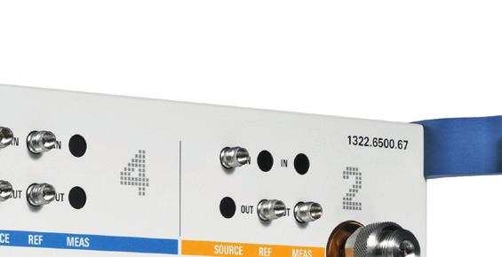
6 Compact solution with open architecture Signal flow between the R&S ZVA and the R&S ZVAX TRM The output signals from the R&S ZVA are fed directly to the R&S ZVAX-TRM via the analyzer s source outputs (SOURCE OUT): In the case of ports 1 and 2, the ports of the R&S ZVAX-TRM extension unit take over the functions of the network analyzer ports. The internal couplers of the R&S ZVA are not used, or they can be used like external couplers in the test setup. The reference and measured signals are transferred to the R&S ZVA from the couplers in the R&S ZVAX-TRM via the analyzer's reference/ measurement inputs (R&S ZVAxx-B16 options) In the case of ports 3 and 4, the output signals from the network analyzer are modified in the R&S ZVAX-TRM and returned to the R&S ZVA together with the reference signals. In this case, the ports of the network analyzer are used Signal routing for R&S ZVA port 1 and R&S ZVAX-TRM port 1, and for R&S ZVA port 2 and R&S ZVAX-TRM port 2 Signal routing for R&S ZVA port 3 and port 4 via R&S ZVAX TRM ZVA port 1 or port 2 ZVA port 3 or port 4 Reference Measurement Reference Measurement Source signals from port 3 or 4 to combiner Pulse modulator Output amplifier Combiner CW reference signal (ahead of pulse modulator) ZVAX-TRM LNA Pulse modulator Output amplifier Combiner ZVAX-TRM combiner active: RF to port 1 or port 2 ZVAX-TRM Port 1 or port 2 6
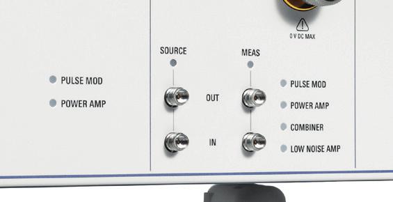
7 Signal access points in the R&S ZVAX TRM for integrating external components and instruments Different measurement tasks, e.g. measuring power or pulse profile, call for different test setups. To meet these requirements, the R&S ZVAX-TRM offers the following possibilities: Access to the generator paths of R&S ZVAX-TRM ports 1 and 2 for connecting external power amplifiers and isolators Access to the receiver paths of R&S ZVAX-TRM ports 1 and 2 for connecting attenuators for power measurements. Via a mechanical switch, the measured signal can be output to an external instrument such as a spectrum analyzer or power sensor Access to reference signal at various points. This feature mainly serves to utilize the automatic level control (ALC) function of the R&S ZVA in applications that call for highly precise output powers. The reference signal can be accessed at various points: Access ahead of pulse modulator (1): In the case of very short pulses, the ALC may not be able to directly evaluate the modulated input signal due to its finite settling time. In such cases, the (unmodulated) signal ahead of the pulse modulator can be used for level control Access after output amplifier and pulse modulator (2): Allows undesired drift effects from the output amplifier to be taken into account Access after combiner in R&S ZVAX-TRM (3): Takes into account undesired drift effects from all components in a test setup that lie ahead of the reference plane (calibration plane) Access points for reference signal (depending on signal path and options installed) Combiner Pulse modulator Output amplifier (1) (2) (3) Reference channel access points Rohde & Schwarz R&S ZVAX-TRM Extension Unit 7
8 Customized configuration R&S ZVAX TRM base unit The R&S ZVAX-TRM base unit contains all the required control interfaces and trigger inputs and outputs, plus the high-power couplers for ports 1 and 2, as well as access to the R&S ZVAX-TRM generator and receiver paths. In its basic configuration, the R&S ZVAX-TRM supports high-power two-port measurements up to +43 dbm. For these measurements, it may be necessary to loop external preamplifiers and/or isolators into the generator path. External attenuators may have to be looped into the receiver path in order to prevent receiver compression. These additional components must be dimensioned to match the required application and therefore need to be supplied by the customer. R&S ZVAX TRMxx base unit (without options) Src Out Src In Src 2 In Port 2 Ref 2 Out Meas 2 Out Meas Out Meas In Src Out Src In Src 1 In Port 1 Ref 1 Out Meas 1 Out Meas Out from/to VNA Meas In 8
9 R&S ZVAXxxB712/B73 pulse modulators These options expand the base unit with up to three pulse modulators that can be inserted into the signal paths of ports 1, 2 and 3. Using an R&S ZVAX-TRM equipped with these options, a two-port R&S ZVA can perform bidirectional pulse measurements. A four-port R&S ZVA with two or four internal sources supports intermodulation measurements on pulsed signals. Pulsed measurements are configured in the R&S ZVA firmware. The pulse modulators are controlled via an interface on the R&S ZVAX- TRM rear panel or with an external pulse generator. Each pulse modulator contains an internal splitter, allowing the unmodulated signal to be used as a reference. R&S ZVAXxxB31/B32 low-noise preamplifiers These options can be inserted into the R&S ZVAX-TRM receiver paths to allow noise figure measurements on low gain, low noise figure DUTs. R&S ZVAXxxB112/B134 output amplifiers These options add two amplifiers to ports 1 and 2 and ports 3 and 4 as a group in each case. The amplifiers optimally compensate for frequency-dependent internal losses in the R&S ZVAX-TRM, allowing the output power levels of an R&S ZVA base unit to be achieved even with a fully configured R&S ZVAX-TRM (all options installed). Higher power levels require the insertion of a user-supplied output amplifier. R&S ZVAXxxB213/B224 combiners These options greatly simplify intermodulation and group delay measurements on mixers since the source signals from R&S ZVA ports 1 and 3 and from ports 2 and 4 are combined into two-tone signals already in the R&S ZVAX-TRM. This allows a four-port R&S ZVA with two internal sources to measure a T/R module s intermodulation characteristics in both directions. R&S ZVAX TRM with all options Meas 2 Out Ref 2 Out Src 2 In R&S ZVAXxxB32 Meas In Meas Out Ref 4 In Ref 4 Out R&S ZVAXxxB224 Port 2 Src In Src Out Src 4 In Src 4 Out R&S ZVAXxxB712 R&S ZVAXxxB112 R&S ZVAXxxB31 Meas 1 Out Ref 1 Out Src 1 In Ref 3 In Ref 3 Out R&S ZVAXxxB73 R&S ZVAXxxB134 R&S ZVAXxxB213 Meas In Meas Out Port 1 Src In Src Out Src 3 In Src 3 Out from/to NWA R&S ZVAX-TRMxx frontend/ports Rohde & Schwarz R&S ZVAX-TRM Extension Unit 9


10 R&S ZVAX TRM interfaces and control Configuration of R&S ZVAX TRM extension unit The R&S ZVAX TRM is configured and controlled in the R&S ZVA firmware. A straightforward block diagram shows all switch positions and signal paths, so that the user has everything in view and can adapt the active setup as required with a mouse click. The various measurement configurations are saved as part of the R&S ZVA instrument setup and are available at any time. In the R&S ZVAX TRM configuration dialog, the user parameterizes the two sweep synchronous pulse trigger generators in the R&S ZVA and allocates them to up to three optional pulse modulators in the R&S ZVAX TRM. Alternatively, trigger signals from external generators can be used to control the pulse modulators in the R&S ZVAX-TRM, e.g. during antenna measurements. Configuration of the R&S ZVAX-TRM on the R&S ZVA. Parameterizing the pulse generators in the R&S ZVA. 10

11 Rear-panel interfaces The mechanical switches in the R&S ZVAX TRM are controlled via a USB interface on the rear (USB FROM NWA). The R&S ZVA has two optional internal pulse trigger generators that are used to control the pulse modulators in the R&S ZVAX TRM. The pulse generator signals from the R&S ZVA are transferred to the extension unit via the CAS- CADE interface. Alternatively, external signals can be used to control the R&S ZVAX TRM pulse modulators. These signals are applied via the EXT PULSE GENERATOR IN ports. Two BNC connectors (PULSE GENERATOR OUT) are available for monitoring pulse generator signals looped through from the R&S ZVA and for controlling external switches. The R&S ZVAX-TRM also contains an extra, standard USB interface on its rear for connecting storage media, a mouse, keyboard, etc. Integration of the R&S ZVAX TRM therefore does not reduce the number of USB ports available for connecting peripheral equipment. Two further USB connectors are provided on the R&S ZVAX TRM front panel, e.g. for connecting R&S NRP Zxx power sensors. R&S ZVAX TRM rear-panel interfaces Standard USB interface Control of pulse modulators USB interface for control signals from R&S ZVA Output of pulse generator signals Input for external pulse generator signals Rohde & Schwarz R&S ZVAX TRM Extension Unit 11

12 Typical system configurations Measurements on T/R modules with combined transmit/receive ports An especially compact and straightforward test setup is obtained for T/R modules whose RX/TX paths are combined by switching them to a single port. In conjunction with a four-port R&S ZVA with four internal sources, the following signals can be provided without external generators: RF input signal, RF two-tone signal, and the LO 1 and LO 2 auxiliary signals. This configuration is not only highly compact, it also delivers exceptionally high measurement speed, since the internal signal sources operate synchronously with one another and also with the sweep, eliminating the need for controlling an external generator. A T/R module needs to be connected only once to allow its full characterization, including in particular the following parameters and features: Measurement of RX and TX paths Gain, matching, conversion gain Phase, group delay Compression, intermodulation Noise figure Bidirectional pulsed measurements Hot S22 RX/TX crosstalk Flexible configuration, e.g. RX and TX gain as a function of LO levels Direct control of DUT switches via R&S ZVA USER CONTROL port (TTL signals) Measuring a T/R module with combined transmit/ receive ports D LO 2 RF forward LO 1 RF reverse Rx Antenna port Tx 12
13 Measurements on T/R modules with an input circulator (three ports) Somewhat more complex are T/R modules with separate RX and TX ports. Using an R&S ZVA with four internal sources allows the key parameters to be determined even for this type of module without having to change the DUT connections: Measurement of RX path (blue lines) RF signal from R&S ZVAX TRM port 1 (CW, pulsed, two-tone signal) LORX from R&S ZVA port 4 Measurement of TX path (red lines) RF signal from R&S ZVAX TRM port 2 (CW, pulsed, two-tone signal) LOTX from R&S ZVA port 3 Measurement parameters for RX and TX paths same as for modules with combined RX/TX ports, but without hot S 22 and RX/TX crosstalk measurements High-power and hot S 22 measurements An important test on power amplifiers is the hot S 22 measurement, which involves determining the output power matching of an amplifier working under load conditions. For this measurement, a stimulus signal is output at R&S ZVAX TRM port 1, and the output power matching (S 22 ) is measured at port 2. Depending on the output power level, additional components such as an isolator or attenuator may be required. The R&S ZVAX TRM ports can handle a maximum input power of +43 dbm; higher power levels can be processed by using appropriate external components (isolator, attenuator, etc.). Measuring a T/R module with a circulator at its input (three ports) Test setup for high-power and hot S 22 amplifier measurements D D LO TX RF TX path Preamplifier (if required) Hot S 22 stimulation and measurement RF RX path TX Ant DUT High-power output signal (up to +43 dbm; higher powers possible with external components) RX LO RX Rohde & Schwarz R&S ZVAX TRM Extension Unit 13
14 Key specifications Specifications Maximum input power at test port base unit +43 dbm 1) Rise time R&S ZVAXxxB712/B73 pulse modulator options < 10 ns On/off ratio at 10 GHz Pulse droop Trigger delay Output power (depending on installed options and R&S ZVA output power) with R&S ZVAXxxB112/B134 output amplifier options > 60 db typ db Dynamic range with all options installed up to 24 GHz > 120 db up to 40 GHz > 110 db up to 50 GHz > 100 db up to 67 GHz > 90 db < 25 ns > 5 dbm to 15 dbm 1) Higher powers can be provided and handled by using external components, e.g. preamplifier, attenuator, etc. For data sheet, see PD and Service options Extended Warranty, one year R&S WE1 Please contact your local Extended Warranty, two years R&S WE2 Rohde & Schwarz sales office. Extended Warranty, three years Extended Warranty, four years Extended Warranty with Calibration Coverage, one year Extended Warranty with Calibration Coverage, two years Extended Warranty with Calibration Coverage, three years Extended Warranty with Calibration Coverage, four years R&S WE3 R&S WE4 R&S CW1 R&S CW2 R&S CW3 R&S CW4 14
15 Ordering information Designation Type Order No. Base unit 1) Unit for installation of R&S ZVAX24Bxxx options, 10 MHz to 24 GHz, R&S ZVAX TRM to extend the measurement capabilities of an R&S ZVA/R&S ZVT with B16 option Unit for installation of R&S ZVAX40Bxxx options, 10 MHz to 40 GHz, R&S ZVAX TRM to extend the measurement capabilities of an R&S ZVA/R&S ZVT with B16 option Unit for installation of R&S ZVAX50Bxxx options, 10 MHz to 50 GHz, R&S ZVAX TRM to extend the measurement capabilities of an R&S ZVA/R&S ZVT with B16 option Unit for installation of R&S ZVAX67Bxxx options, 10 MHz to 67 GHz, R&S ZVAX TRM to extend the measurement capabilities of an R&S ZVA/R&S ZVT with B16 option Options Options for R&S ZVAX-TRM24 Pulse modulators for R&S ZVAX TRM24, 10 MHz to 24 GHz, to generate pulsed signals R&S ZVAX24B at R&S ZVAX TRM24 port 1 and port 2 Pulse modulator for R&S ZVAX TRM24, 10 MHz to 24 GHz, to generate pulsed signals R&S ZVAX24B at network analyzer port 3 or at R&S ZVAX TRM24 port 1 (B213 option active) Output amplifiers for R&S ZVAX TRM24, 10 MHz to 24 GHz, for increased output power R&S ZVAX24B at R&S ZVAX TRM24 port 1 and port 2 Output amplifiers for R&S ZVAX TRM24, 10 MHz to 24 GHz, for increased output power at network R&S ZVAX24B analyzer port 3 and port 4 or at R&S ZVAX TRM24 port 1 and port 2 (B213/B224 option active) Combiner for R&S ZVAX TRM24, 10 MHz to 24 GHz, to generate two-tone signal R&S ZVAX24B at R&S ZVAX TRM port 1 (SRC 1 + 3) Combiner for R&S ZVAX TRM24, 10 MHz to 24 GHz, to generate two-tone signal R&S ZVAX24B at R&S ZVAX TRM port 2 (SRC 2 + 4) Low-noise preamplifier for R&S ZVAX-TRM24 (port 1 measurement path), 10 MHz to 24 GHz R&S ZVAX24B Low-noise preamplifier for R&S ZVAX-TRM24 (port 2 measurement path), 10 MHz to 24 GHz R&S ZVAX24B Options for R&S ZVAX-TRM40 Pulse modulators for R&S ZVAX TRM40, 10 MHz to 40 GHz, to generate pulsed signals R&S ZVAX40B at R&S ZVAX TRM40 port 1 and port 2 Pulse modulator for R&S ZVAX TRM40, 10 MHz to 40 GHz, to generate pulsed signals R&S ZVAX40B at network analyzer port 3 or at R&S ZVAX TRM40 port 1 (B213 option active) Output amplifiers for R&S ZVAX TRM40, 10 MHz to 40 GHz, for increased output power R&S ZVAX40B at R&S ZVAX TRM40 port 1 and port 2 Output amplifiers for R&S ZVAX TRM40, 10 MHz to 40 GHz, for increased output power at network R&S ZVAX40B analyzer port 3 and port 4 or at R&S ZVAX TRM40 port 1 and port 2 (B213/B224 option active) Combiner for R&S ZVAX TRM40, 10 MHz to 40 GHz, to generate two-tone signal R&S ZVAX40B at R&S ZVAX TRM port 1 (SRC 1 + 3) Combiner for R&S ZVAX TRM40, 10 MHz to 40 GHz, to generate two-tone signal R&S ZVAX40B at R&S ZVAX TRM port 2 (SRC 2 + 4) Low-noise preamplifier for R&S ZVAX-TRM40 (port 1 measurement path), 10 MHz to 40 GHz R&S ZVAX40B Low-noise preamplifier for R&S ZVAX-TRM40 (port 2 measurement path), 10 MHz to 40 GHz R&S ZVAX40B Options for R&S ZVAX-TRM50 Pulse modulators for R&S ZVAX TRM50, 10 MHz to 50 GHz, to generate pulsed signals R&S ZVAX50B at R&S ZVAX TRM50 port 1 and port 2 Pulse modulator for R&S ZVAX TRM50, 10 MHz to 50 GHz, to generate pulsed signals R&S ZVAX50B at network analyzer port 3 or at R&S ZVAX TRM50 port 1 (B213 option active) Output amplifiers for R&S ZVAX TRM50, 10 MHz to 50 GHz, for increased output power R&S ZVAX50B at R&S ZVAX TRM50 port 1 and port 2 Output amplifiers for R&S ZVAX TRM50, 10 MHz to 50 GHz, for increased output power at network R&S ZVAX50B analyzer port 3 and port 4 or at R&S ZVAX TRM50 port 1 and port 2 (B213/B224 option active) Combiner for R&S ZVAX TRM50, 10 MHz to 50 GHz, to generate two-tone signal R&S ZVAX50B at R&S ZVAX TRM port 1 (SRC 1 + 3) Combiner for R&S ZVAX TRM50, 10 MHz to 50 GHz, to generate two-tone signal R&S ZVAX50B at R&S ZVAX TRM port 2 (SRC 2 + 4) Low-noise preamplifier for R&S ZVAX-TRM50 (port 1 measurement path), 10 MHz to 50 GHz R&S ZVAX50B Low-noise preamplifier for R&S ZVAX-TRM50 (port 2 measurement path), 10 MHz to 50 GHz R&S ZVAX50B ) Placeholders in R&S ZVAX-TRMxx base unit and R&S ZVAXxxTRMyyy option types: xx = 24/40/50/67, yyy = option type. Rohde & Schwarz R&S ZVAX TRM Extension Unit 15
16 Designation Type Order No. Options for R&S ZVAX-TRM67 Pulse modulators for R&S ZVAX TRM67, 10 MHz to 67 GHz 2), to generate pulsed signals at R&S ZVAX67B R&S ZVAX TRM67 port 1 and port 2 Pulse modulator for R&S ZVAX TRM67, 10 MHz to 67 GHz 2), to generate pulsed signals at network R&S ZVAX67B analyzer port 3 or at R&S ZVAX TRM67 port 1 (B213 option active) Output amplifiers for R&S ZVAX TRM67, 10 MHz to 67 GHz, for increased output power R&S ZVAX67B at R&S ZVAX TRM67 port 1 and port 2 Output amplifiers for R&S ZVAX TRM67, 10 MHz to 67 GHz, for increased output power at network R&S ZVAX67B analyzer port 3 and port 4 or at R&S ZVAX TRM port 1 and port 2 (B213/B224 option active) Combiner for R&S ZVAX TRM67, 10 MHz to 67 GHz, to generate two-tone signal R&S ZVAX67B at R&S ZVAX TRM67 port 1 (SRC 1 + 3) Combiner for R&S ZVAX TRM67, 10 MHz to 67 GHz, to generate two-tone signal R&S ZVAX67B at R&S ZVAX TRM67 port 2 (SRC 2 + 4) Low-noise preamplifier for R&S ZVAX-TRM67, 10 MHz to 50 GHz 3), port 1 measurement path R&S ZVAX50B Low-noise preamplifier for R&S ZVAX-TRM67, 10 MHz to 50 GHz 3), port 2 measurement path R&S ZVAX50B Accessories 19" Rackmount Kit for R&S ZVA R&S ZZA " Rackmount Kit for R&S ZVAX-TRMxx (including a set of shortened RF rigid interconnection cables) R&S ZZA-ZVAX xx xx = 24/40/50/67 2) Limited performance above 60 GHz. 3) Operation limited to 50 GHz. Rohde & Schwarz R&S ZVAX TRM Extension Unit 16
17 From pre-sale to service. At your doorstep. The Rohde & Schwarz network in over 70 countries ensures optimum on-site support by highly qualified experts. User risks are reduced to a minimum at all stages of the project: Solution finding/purchase Technical startup/application development/integration Training Operation/calibration/repair Finland Norway Sweden Estonia Denmark United Kingdom Netherlands Poland Latvia Lithuania Russian Federation Czech Republic Ukraine France Austria Hungary Slovenia Switzerland Romania Spain Portugal Italy Serbia Bulgaria Greece Turkey Azerbaijan Canada Malta Cyprus Cologne Germany Portland Ottawa Munich Kazakhstan Mongolia Sales level USA Los Angeles Dallas Monterrey Mexico Mexico City Columbia/Maryland Algeria Senegal Tunisia Israel Egypt Azerbaijan Jordan UAE Saudi Arabia Islamabad Pakistan Karachi Oman Beijing Japan Seoul Xi'an South Daejeon Tokyo Korea Kanagawa Chengdu Gumi City China Osaka Shanghai New Delhi Guangzhou Taipei India Shenzhen Taiwan Mumbai Kaohsiung Hong Hyderabad Hanoi Kong Vietnam Sales locations Service level Backup service Area support center Colombia Brazil Nigeria Kenya Ho Chi Thailand Bangalore Minh City Penang Malaysia Selangor Singapore Indonesia Philippines Local service center Calibration and maintenance with standardized automatic calibration systems Calibration and maintenance Maintenance Chile Rio de Janeiro São Paulo Uruguay Argentina South Africa Australia Melbourne Sydney Canberra New Zealand Rohde & Schwarz R&S ZVAX TRM Extension Unit 17
18 Service that adds value Worldwide Local and personalized Customized and flexible Uncompromising quality Long-term dependability About Rohde & Schwarz The Rohde & Schwarz electronics group offers innovative solutions in the following business fields: test and measurement, broadcast and media, secure communications, cybersecurity, radiomonitoring and radiolocation. Founded more than 80 years ago, this independent company has an extensive sales and service network and is present in more than 70 countries. The electronics group is among the world market leaders in its established business fields. The company is headquartered in Munich, Germany. It also has regional headquarters in Singapore and Columbia, Maryland, USA, to manage its operations in these regions. Sustainable product design Environmental compatibility and eco-footprint Energy efficiency and low emissions Longevity and optimized total cost of ownership Certified Quality Management ISO 9001 Certified Environmental Management ISO Rohde & Schwarz GmbH & Co. KG Regional contact Europe, Africa, Middle East North America TEST RSA ( ) customer.support@rsa.rohde-schwarz.com Latin America customersupport.la@rohde-schwarz.com Asia Pacific customersupport.asia@rohde-schwarz.com China customersupport.china@rohde-schwarz.com R&S is a registered trademark of Rohde & Schwarz GmbH & Co. KG Trade names are trademarks of the owners PD Version July 2015 (as) R&S ZVAX TRM Extension Unit Data without tolerance limits is not binding Subject to change Rohde & Schwarz GmbH & Co. KG Munich, Germany PDP 1 en
R&S SMZ Frequency Multiplier Precise andadjustable output levels from 50 GHz to 110 GHz
 Test & Measurement Product Brochure 01.00 R&S SMZ Frequency Multiplier Precise andadjustable output levels from 50 GHz to 110 GHz R&S SMZ Frequency Multiplier At a glance The new R&S SMZ family of frequency
R&S ZVA-Zxx Millimeter-Wave Converters Network analysis up to 500 GHz
 ZVA-Zxx_bro_en_5214-2033-12.indd 1 Product Brochure 06.02 Test & Measurement R&S ZVA-Zxx Millimeter-Wave Converters Network analysis up to 500 GHz 28.10.2014 21:05:04 R&S ZVA-Zxx Millimeter-Wave Converters
R&S THR9 Liquid-Cooled FM Transmitter Family Highest efficiency, smallest footprint
 THR9_bro_en_3606-8595_12_v0101.indd 1 Product Brochure 01.01 Broadcasting R&S THR9 Liquid-Cooled FM Transmitter Family Highest efficiency, smallest footprint 17.03.2014 14:48:45 R&S THR9 Liquid-Cooled
R&S FSWP Phase Noise Analyzer and VCO Tester High end analysis of signal sources and components
 R&S FSWP Phase Noise Analyzer and VCO Tester High end analysis of signal sources and components year Product Brochure Version 06.01 R&S FSWP Phase Noise Analyzer and VCO Tester At a glance The R&S FSWP
R&S ZVT Vector Network Analyzer Specifications
 ZVT_dat-sw_en_0758-065-22_v0900_cover.indd Data Sheet 09.00 Test & Measurement R&S ZVT Vector Network Analyzer Specifications 06.03.205 5:50:4 CONTENTS Definitions... 3 Specifications... 4 Measurement
R&S ENV216 Two-Line V-Network For disturbance voltage measurements on single-phase EUTs
 R&S ENV216 Two-Line V-Network For disturbance voltage measurements on single-phase EUTs Test & Measurement Data Sheet 03.00 R&S ENV216 Two-Line V-Network At a glance The R&S ENV216 two-line V-network meets
R&S ZVT Vector Network Analyzer Specifications
 R&S ZVT Vector Network Analyzer Specifications Test & Measurement Data Sheet 08.00 CONTENTS Definitions... 3 Specifications... 4 Measurement range...4 Measurement speed...5 Measurement accuracy...6 Effective
R&S RSC Step Attenuator Specifications
 R&S RSC Step Attenuator Specifications Data Sheet Version 05.00 CONTENTS Definitions... 3 Specifications... 4 Step attenuator, 139 db, 1 db steps, DC to 6 GHz (models.03 and.13)... 4 Step attenuator, 139.9
R&S NRPM Over-the-Air (OTA) Power Measurement Solution For 5G, WLAN IEEE ad and IEEE ay
 Power Measurement Solution For 5G, WLAN IEEE ad and IEEE ay") year Product Brochure Version 0.00 R&S NRPM Over-the-Air (OTA) Power Measurement Solution For 5G, WLAN IEEE 80.ad and IEEE 80.ay NRPM_bro_en_607-4687-_v000.indd 8.0.09 5:59:08 R&S NRPM Over-the-Air (OTA)
year Product Brochure Version 0.00 R&S NRPM Over-the-Air (OTA) Power Measurement Solution For 5G, WLAN IEEE 80.ad and IEEE 80.ay NRPM_bro_en_607-4687-_v000.indd 8.0.09 5:59:08 R&S NRPM Over-the-Air (OTA)
Attenuators and Matching Pads, Terminations 75 mw to 1000 W, DC to 18 GHz
 Product Brochure Version 8. Attenuators and Matching Pads, Terminations 75 mw to W, DC to 8 GHz Attenuators_dat-bunt_en_758-96_3_v8.indd 3.3.7 7:33:39 Attenuators As a rule, the reflection coefficient
Noise Figure Measurement Applications Specifications
 Noise Figure Measurement Applications Specifications R&S FSW-K30 R&S FSWP-K30 R&S FPS-K30 R&S FSV-K30 R&S FPL1-K30 Data Sheet Version 02.02 CONTENTS Definitions... 3 Specifications... 4 Frequency... 4
R&S AREG100A Automotive Radar Echo Generator Reliable and simple production testing of automotive radar sensors
 year Product Brochure Version 01.02 R&S AREG100A Automotive Radar Echo Generator Reliable and simple production testing of automotive radar sensors AREG100A_bro_en_3607-7057-12_v0102.indd 1 05.07.2018
R&S ZNBT8 Vector Network Analyzer Specifications
 E stablished 1981 Advanced Test Equipment Rentals www.atecorp.com 800-404-ATEC (2832) ZNBT8_dat-sw_en_3606-9727-22_v0200_cover.indd 1 Data Sheet 02.00 Test & Measurement R&S ZNBT8 Vector Network Analyzer
R&S ZNB Vector Network Analyzer Specifications
 Umschlag_ZNB4-8_dat-sw_en_5214-5384-22.indd 1 Data Sheet 02.00 Test & Measurement R&S ZNB Vector Network Analyzer Specifications 07.11.2011 10:03:35 CONTENTS Definitions... 3 Measurement range... 4 Measurement
R&S ZNC Vector Network Analyzer Specifications
 ZNC3_dat-sw_en_5214-5610-22_v0300_cover.indd 1 Data Sheet 03.00 Test & Measurement R&S ZNC Vector Network Analyzer Specifications 04.09.2012 13:39:47 CONTENTS Definitions... 3 Measurement range... 4 Measurement
R&S FSC Spectrum Analyzer Specifications
 R&S FSC Spectrum Analyzer Specifications year Data Sheet Version 03.00 CONTENTS Base unit... 3 Frequency... 3 Sweep time... 3 Bandwidths... 3 Level... 4 Trigger functions... 5 Tracking generator (model.13/.16
The compact test- disconnect terminal interface system for protection and secondary technology
 POCON POWER Connector The compact test- disconnect terminal interface system for protection and secondary technology POCON the compact test-disconnect terminal interface system Safe control and testing
R&S ZV-Z3xx T-Checker Specifications
 ZV-Z3xx_dat-sw_en_3607-0575-22_cover.indd 1 Data Sheet 01.00 Test & Measurement R&S ZV-Z3xx T-Checker Specifications 17.06.2014 15:14:20 CONTENTS Definitions... 3 Specifications... 4 Measurement range...
Regulatory status for using RFID in the UHF spectrum 3 May 2006
 Regulatory status for using RFID in the UHF spectrum 3 May NOTE: The following countries were updated since the last publication of 3 March : Thailand, Romania. The table attached provides an overview
R&S ZN-Z5x Calibration Units Specifications. Data Sheet V03.00
 R&S ZN-Z5x Calibration Units Specifications Data Sheet V03.00 CONTENTS Definitions... 4 Specifications... 6 Model description R&S ZN-Z5x... 6 Model description R&S ZN-Z15x... 7 Input power limits... 7
CISCO ONS /100-GHZ INTERLEAVER/DE-INTERLEAVER FOR THE CISCO ONS MULTISERVICE TRANSPORT PLATFORM
 DATA SHEET CISCO ONS 15216 50/100-GHZ INTERLEAVER/DE-INTERLEAVER FOR THE CISCO ONS 15454 MULTISERVICE TRANSPORT PLATFORM The Cisco ONS 15216 50/100-GHz Interleaver/De-interleaver is an advanced 50/100-GHz
R&S FU129 Antenna Filter Unit Antenna switching, rotator control and signal attenuation, amplification and filtering
 Radiomonitoring & Radiolocation Product Brochure 02.01 R&S FU129 Antenna Filter Unit Antenna switching, rotator control and signal attenuation, amplification and filtering R&S FU129 Antenna Filter Unit
R&S ZN-Zxxx Calibration Units Specifications. Data Sheet V04.00
 R&S ZN-Zxxx Calibration Units Specifications Data Sheet V04.00 Version 03.00, January 2019 CONTENTS Definitions... 4 Specifications... 6 Model description R&S ZN-Z5x... 6 Model description R&S ZN-Z15x...
Power Added Efficiency Measurement with R&S ZNB/ R&S ZVA
 Power Added Efficiency Measurement with R&S ZNB/ R&S ZVA Application Note Products: R&S ZNB R&S ZVA Power Added Efficiency (PAE) is a key parameter for the characterization of an amplifier. This application
R&S SMB100A RF and Microwave Signal Generator Versatile, compact solution for signal generation up to 40 GHz
 Test & Measurement Product Brochure 04.00 R&S SMB100A RF and Microwave Signal Generator Versatile, compact solution for signal generation up to 40 GHz R&S SMB100A RF and Microwave Signal Generator At a
Who Reads and Who Follows? What analytics tell us about the audience of academic blogging Chris Prosser Politics in
 Who Reads and Who Follows? What analytics tell us about the audience of academic blogging Chris Prosser Politics in Spires @caprosser 1 What do we want to know about the audience for academic blogging?
Frame through-beam sensors
 Frame through-beam sensors Features Wide range of sizes: passage sizes from 25 x 23 mm to 300 x 397.5 mm Metal housings Integrated evaluation unit Connection by means of connector Degree of protection
R&S TS8997 Regulatory Test System for Wireless Devices
 R&S TS8997 Regulatory Test System for Wireless Devices Product Brochure Version 03.01 ETSI EN 300328 V1.8.1/ETSI EN 301893 V1.7.1 compliance tests in the 2.4/5 GHz band TS8997_bro_en_3606-8095-12_v0301.indd
R&S ZV-Z5x Calibration Units Specifications
 R&S ZV-Z5x Calibration Units Specifications Test & Measurement Data Sheet 10.00 Specifications apply under the following conditions: Sufficient warm-up time (approx. 15 minutes) at ambient temperature,
WOODWORKING TECHNOLOGY IN EUROPE: HIGHLIGHTS European Federation of Woodworking Technology Manufacturers
 European Federation of Woodworking Technology Manufacturers ADVANCED ECONOMIES - GDP % GROWTH RATE 2017 8,0 7,0 6,0 5,0 4,0 3,0 2,0 1,0 0,0 Ireland Malta Slovenia Estonia Latvia Czech Republic Cyprus
Analog Modulation Analysis (AM/FM/φM) Specifications
 Specifications") Analog Modulation Analysis (AM/FM/φM) Specifications R&S FSW-K7 R&S ESW-K7 R&S FSWP-K7 R&S FSV-K7 R&S FSL-K7 R&S FPS-K7 R&S FPL1-K7 R&S VSE-K7 Data Sheet Version 06.00 CONTENTS Definitions... 3 Specifications...
Analog Modulation Analysis (AM/FM/φM) Specifications R&S FSW-K7 R&S ESW-K7 R&S FSWP-K7 R&S FSV-K7 R&S FSL-K7 R&S FPS-K7 R&S FPL1-K7 R&S VSE-K7 Data Sheet Version 06.00 CONTENTS Definitions... 3 Specifications...
R&S ZV-Z135 Calibration Kit Specifications
 R&S ZV-Z135 Calibration Kit Specifications Test & Measurement Data Sheet 01.01 CONTENTS Definitions... 3 Specifications... 4 Mechanical data... 4 Electrical data of R&S ZV-Z135 (3.5 mm, female)... 4 Electrical
Group Delay measurements with Signal and Spectrum Analyzers Application Note
 Group Delay measurements with Signal and Spectrum Analyzers Application Note Products: ı ı R&S FSW R&S FSW-K17 Phase distortions in a transmission channel are determined using group delay measurements,
Cisco ONS Metropolitan Dense Wavelength Division Multiplexing 100-GHz FlexLayer Filter Solution
 Data Sheet Cisco ONS 15216 Metropolitan Dense Wavelength Division Multiplexing 100-GHz FlexLayer Filter Solution The Cisco ONS 15216 Metropolitan Dense Wavelength-Division Multiplexing (DWDM) FlexLayer
Through-beam ring sensors
 Throughbeam ring sensors Features Wide range of sizes: ring diameters of 10, 15 and 20 mm Metal housings Separate evaluation unit Connection by means of S8 connector Degree of protection IP 63 Adjustable
Vector Network Analyzers ZVB
 Specifications Version 05.00 Vector Network Analyzers ZVB September 2005 Specifications MEASUREMENT RANGE...3 MEASUREMENT SPEED...5 MEASUREMENT ACCURACY...6 EFFECTIVE SYSTEM DATA...8 TEST PORT OUTPUT...8
Testing S-Parameters on Pulsed Radar Power Amplifier Modules
 Application Note Mahmud Naseef, Roland Minihold, Thilo Bednorz 3.2013-1MA126_2E Testing S-Parameters on Pulsed Radar Power Amplifier Modules Application Note Products: ı ı ı ı ı R&S ZVA8 R&S ZVAX24 R&S
R&S FS-K112PC NFC Measurement Software Specifications
 FS_K112-PC_dat-sw_3606-7047-22_cover.indd 1 Data Sheet 03.00 Test & Measurement R&S FS-K112PC NFC Measurement Software Specifications 06.10.2014 18:19:15 CONTENTS Definitions... 3 Specifications... 4 Minimum
Measurement Setup for Phase Noise Test at Frequencies above 50 GHz Application Note
 Measurement Setup for Phase Noise Test at Frequencies above 50 GHz Application Note Products: R&S FSWP With recent enhancements in semiconductor technology the microwave frequency range beyond 50 GHz becomes
Table of Contents Executive Summary 29
 Contents Table of Contents Executive Summary 29 Section 1: Introduction 33 Section 2: World 37 2.1.1. Main consumers 37 2.1.2. Main producers 2015 and 2016 39 2.1.3. Main importers 2015 and 2016 40 2.1.4.
Bring satellites into your lab: GNSS simulators from the T&M expert.
 Bring satellites into your lab: GNSS simulators from the T&M expert. www.rohde-schwarz.com/gnss-solutions Your challenge GNSS receiver tests can only be conclusive when they are performed under realistic
Keysight Technologies Differences in Application Between Power Dividers and Power Splitters. Application Note
 Keysight Technologies Differences in Application Between Dividers and Splitters Application Note 02 Keysight Differences in Application Between Dividers and Splitters Application Note Introduction dividers
Brochure More information from
 Brochure More information from http://www.researchandmarkets.com/reports/1342464/ The World Market for Stranded Wire, Cable, Ropes, and Plaited Bands of Iron, Steel, Copper, or Aluminum Excluding Electrically
R&S FSWP Phase Noise Analyzer and VCO Tester High end analysis of signal sources and components
 R&S FSWP Phase Noise Analyzer and VCO Tester High end analysis of signal sources and components Product Brochure Version 05.00 year FSWP_bro_en_3607-2090-12_v0500.indd 1 17.11.2017 10:00:03 R&S FSWP Phase
MIC5528. High Performance 500 ma LDO in Thin and Extra Thin DFN Packages. General Description. Features. Applications.
 High Performance 500 ma LDO in Thin and Extra Thin DFN Packages Features General Description Applications Package Types Typical Application Circuit Functional Block Diagram 1.0 ELECTRICAL CHARACTERISTICS
stripax The professional stripping tool
 stripax The professional stripping tool stripax the original: developed from experience Weidmüller is the world s leading manufacturer of solutions for electrical connectivity, transmission, conditioning
Introduction. Part 1. Introduction...2
 Keysight Technologies Simple Scalar Network Analysis of Frequency Converter Devices using the U2000 USB Power Sensor Series with the ENA Network Analyzer Application Note Introduction This application
Monthly Summary of Troop Contribution to UN Operations
 Monthly Summary of Troop Contribution to UN Operations Month of Report : 3-Dec-3 Country Description of Post M F Totals ) Albania Individual Police............ 0 Subtotal for Country ) Algeria Experts
R&S ZV-Z5x Calibration Units Specifications
 R&S ZV-Z5x Calibration Units Specifications Test & Measurement Data Sheet 09.01 Specifications apply under the following conditions: Sufficient warm-up time (approx. 15 minutes) at ambient temperature,
Automated Frequency Response Measurement with AFG31000, MDO3000 and TekBench Instrument Control Software APPLICATION NOTE
 Automated Frequency Response Measurement with AFG31000, MDO3000 and TekBench Instrument Control Software Introduction For undergraduate students in colleges and universities, frequency response testing
Introduction. Part 1. Introduction...2
 Keysight Technologies Simple Scalar Network Analysis of Frequency Converter Devices using the U2000 USB Power Sensor Series with the ENA Network Analyzer Application Note Introduction This application
Agilent 87222C/D/E Coaxial Transfer Switches dc to 26.5, 40, 50 GHz
 Agilent 87C/D/E Coaxial Transfer Switches dc to 6.5, 0, 50 GHz Technical Overview High Performance Transfer Switches for Micro wave and RF Instrumentation and Systems Exceptional repeatability for more
Keysight Technologies P9400A/C Solid State PIN Diode Transfer Switches
 Keysight Technologies P9400A/C Solid State PIN Diode Transfer Switches P9400A 100 MHz to 8 GHz PIN transfer switch P9400C 100 MHz to 18 GHz PIN transfer switch Technical Overview Key Features Minimize
R&S CMU-Z10/-Z11 Antenna Coupler/ RF Shielding Cover Simple interference-free testing of all mobiles
 R&S CMU-Z1/-Z11 Antenna Coupler/ RF Shielding Cover Simple interference-free testing of all mobiles Test & Measurement Data Sheet 3. R&S CMU-Z1 /-Z11/-Z1/-Z13/-Z1 At a glance Anyone engaged in mobile phone
Keysight M9485A PXIe Multiport Vector Network Analyzer
 Keysight M9485A PXIe Multiport Vector Network Analyzer 02 Keysight M9485A PXIe Multiport Vector Network Analyzer - Brochure High-Performance PXI Multiport Vector Network Analyzer (VNA) Innovative solution
Economic Outlook for 2016
 Economic Outlook for 2016 Arturo Bris Professor of Finance, IMD Director, IMD World Competitiveness Center Yale International Center for Finance European Corporate Governance Institute 2015 IMD International.
Guide Version Five techniques for fast, accurate power integrity measurements
 Guide Version 01.00 Five techniques for fast, accurate power integrity measurements Rail voltages are getting smaller, and tolerances are decreasing. As a result, making accurate power rail measurements
2018/2019 HCT Transition Period OFFICIAL COMPETITION RULES
 2018/2019 HCT Transition Period OFFICIAL COMPETITION RULES 1. INTRODUCTION These HCT Transition Period Official Competition Rules ( Official Rules ) govern how players earn Hearthstone Competitive Points
Noise Figure Measurement in the 60 GHz Range Application Note
 Noise Figure Measurement in the 60 GHz Range Application Note Products: R&S FSU67 Noisecom Noise Figure Test Set - NC5115-60G - NC5115-60GT This application note describes how noise figure and gain of
Remote participation in Question sessions Audio options VoIP
 Remote participation in Question sessions Remote participation will use GoToMeeting. Participants must be registered to the SG13 meeting in der to be able to join 1. Use your laptop s microphone and speakers
BenchTop Extraction Arms with unbeatable flexibility
 BenchTop Extraction Arms with unbeatable flexibility A new generation of BenchTop extraction arms with unbeatable flexibility Nederman introduces a new generation of BenchTop arms the FX, FX and FX. These
R&S ZNA Vector Network Analyzer Specifications
 R&S ZNA Vector Network Analyzer Specifications Data Sheet Version 01.02 year ZNA_dat-sw_en_5215-4652-22_v0102_cover.indd 1 07.01.2019 12:23:03 Version 01.02 January 2019 CONTENTS Definitions... 3 Measurement
Advanced Test Equipment Rentals ATEC (2832)
") Established 1981 Advanced Test Equipment Rentals www.atecorp.com 8-44-ATEC (2832) Version 2.1 SMF1A Microwave Signal Generator February 29 Signal generation redefined Max. frequency range from 1 khz to
Established 1981 Advanced Test Equipment Rentals www.atecorp.com 8-44-ATEC (2832) Version 2.1 SMF1A Microwave Signal Generator February 29 Signal generation redefined Max. frequency range from 1 khz to
Keysight Technologies USB Preamplifiers
 Keysight Technologies USB Preamplifiers U77/A 1 MHz to 4 GHz U77/C 1 MHz to 6. GHz U77/F to GHz Technical Overview Keysight USB Preamplifiers U77A/C/F - Technical Overview Key Features and Benefits Automatic
R&S EB500 Monitoring Receiver Specifications
 Radiomonitoring & Radiolocation Data Sheet 01.02 R&S EB500 Monitoring Receiver Specifications CONTENTS Definitions... 3 Specifications... 4 Frequency...4 Linearity...4 Interference rejection...4 Noise
R&S SMA100A Signal Generator The new standard of excellence in the analog signal generator class
 SMA100A_bro_en_5213-6412-12.indd 1 Product Brochure 06.01 Test & Measurement R&S SMA100A Signal Generator The new standard of excellence in the analog signal generator class 04.06.2013 10:13:49 R&S SMA100A
Keysight Technologies Achieving Accurate E-band Power Measurements with E8486A Waveguide Power Sensors. Application Note
 Keysight Technologies Achieving Accurate E-band Power Measurements with Waveguide Power Sensors Application Note Introduction The 60 to 90 GHz spectrum, or E-band, has been gaining more millimeter wave
R&S TS-EMF EMF Measurement System Easy, frequency-selective measurement of EMF emissions
 TS-EMF_dat_en_0758-2777-12_v0501.indd 1 Product Brochure 05.01 Test & Measurement R&S TS-EMF EMF Measurement System Easy, frequency-selective measurement of EMF emissions 11.04.2016 09:35:59 R&S TS-EMF
Making a S11 and S21 Measurement Using the Agilent N9340A
 Making a S11 and S21 Measurement Using the Agilent N9340A Application Note Introduction Spectrum characteristics are important in wireless communication system maintenance. Network and spectrum analyzers
Sure Cross Radio Certifications
 Sure Cross Radio Certifications Banner's Sure Cross product line is certified by the FCC, European Union, and many other countries for operation within specific radio frequencies. FCC Certification, 900MHz
R&S CBT/R&S CBT32 Bluetooth Tester Specifications
 Established 1981 Advanced Test Equipment Rentals www.atecorp.com 800-404-ATEC (2832) R&S CBT/R&S CBT32 Bluetooth Tester Specifications Test & Measurement Data Sheet 06.00 CONTENTS Unit specifications...
Agilent N8480 Series Thermocouple Power Sensors. Technical Overview
 Agilent N8480 Series Thermocouple Power Sensors Technical Overview Introduction The new N8480 Series power sensors replace and surpass the legacy 8480 Series power sensors (excluding the D-model power
Keysight M940xA PXIe Optical Extenders for Instrumentation. Data Sheet
 Keysight M940xA PXIe Optical Extenders for Instrumentation Data Sheet Overview Introduction The Keysight Technologies, Inc. Optical Extenders for Instruments can transmit your RF or Microwave signal without
Agilent U9397A/C FET Solid State Switches (SPDT)
") Agilent U9397A/C FET Solid State Switches (SPDT) U9397A 300 khz to 8 GHz U9397C 300 khz to 18 GHz Technical Overview Key Features Prevent damage to sensitive components with low video leakage < 10 mvpp
Agilent U9397A/C FET Solid State Switches (SPDT) U9397A 300 khz to 8 GHz U9397C 300 khz to 18 GHz Technical Overview Key Features Prevent damage to sensitive components with low video leakage < 10 mvpp
Agilent N4000A, N4001A, N4002A SNS Series Noise Sources 10 MHz to 26.5 GHz
 Agilent N4000A, N4001A, N4002A SNS Series Noise Sources 10 MHz to 26.5 GHz Technical Overview Advances in Noise Figure Accuracy N4000A Used for low noise figure devices or devices sensitive to mismatch
Keysight Technologies N9310A RF Signal Generator
 Keysight Technologies N9310A RF Signal Generator 02 Keysight N9310A RF Signal Generator Brochure All the capability and reliability of a Keysight instrument you need at a price you ve always wanted Reliable
Agilent 87075C Multiport Test Set
 Agilent 87075C Multiport Test Set Technical Overview A complete 75 Ω system for cable TV device manufacturers Now, focus on testing, not reconnecting! For use with the Agilent 8711 C-Series of network
Agilent N9310A RF Signal Generator. All the capability and reliability of an Agilent instrument you need at a price you ve always wanted
 Agilent N9310A RF Signal Generator All the capability and reliability of an Agilent instrument you need at a price you ve always wanted Reliable Performance. Essential Test Capability The N9310A RF signal
R&S ZVL Vector Network Analyzer Specifications
 R&S ZVL Vector Network Analyzer Specifications Data Sheet Version 10.00 CONTENTS Definitions... 3 Specifications... 4 Measurement range... 4 Measurement speed... 4 Measurement accuracy... 5 Effective system
MSCI GLOBAL MARKET ACCESSIBILITY REVIEW JUNE Competitive landscape
 DEVELOPED MARKETS Americas Canada USA Austria Belgium Denmark Finland France Germany Ireland Israel Italy Netherlands Investor qualification requirement ++ ++ ++ ++ ++ ++ ++ ++ ++ ++ ++ ++ Foreign ownership
CORIAN SOLID SURFACE. The Latin-America 54 colour portfolio
 CORIAN SOLID SURFACE The Latin-America 54 colour portfolio This Corian Solid Surface paper palette is a flexible, handy and lightweight tool composed of high-definition printed paper samples which give
R&S CLGD DOCSIS Cable Load Generator Multichannel signal generator for DOCSIS 3.1 downstream and upstream
 CLGD_bro_en_3607-0123-12_v0200.indd 1 Product Brochure 02.00 Broadcast & Media Test & Measurement R&S CLGD DOCSIS Cable Load Generator Multichannel signal generator for downstream and upstream 24.07.2015
NFC Forum: The Evolution of a Consortium
 NFC Forum: The Evolution of a Consortium Presented by Greg Kohn Sr. Operations Director, NFC Forum ANSI Open Forum: Building Bridges across the Standards Ecosystem October 9, 2012 Part of the World Standards
Agilent E5061B Network Analyzer. 100 khz to 1.5 GHz/3 GHz 5 Hz to 3 GHz
 Agilent E5061B Network Analyzer 100 khz to 1.5 GHz/3 GHz 5 Hz to 3 GHz E5061B responds to various measurement needs, - from LF to RF The Agilent E5061B is a member of the industry standard ENA Series network
R&S SMC100A Signal Generator Specifications
 R&S SMC100A Signal Generator Specifications Test & Measurement Data Sheet 01.00 CONTENTS Key features... 3 Specifications... 4 RF characteristics...4 Frequency...4 Frequency sweep...4 Reference frequency...4
Wideband mm-wave Signal Generation and Analysis
 Application Note R Minihold, R. Wagner 7.2017 1MA257_3e Wideband mm-wave Signal Generation and Analysis Application Note Products: R&S SMW200A R&S FSW R&S SMB100A R&S FSW-B2000 R&S SMF100A R&S FSW-B21
Signal Generator SMA100A
 Product brochure Version 02.01 Signal Generator SMA100A November 2006 The new standard of excellence in the analog signal generator class Excellent signal quality Ideal for use in production All-purpose
Modulation Accuracy Measurements of DVB-S2 and DVB-S2X Signals Application Note
 Modulation Accuracy Measurements of DVB-S2 and DVB-S2X Signals Application Note Products: ı ı ı ı R&S FSW-K70 R&S FSW-K70M R&S FPS-K70 R&S VSE-K70 This Application Note gives a short overview how signals
HF Transmit/Receive Broadband System XB 2900
 Data sheet HF Transmit/Receive Broadband System XB 2900 Especially designed for naval operational environment Full HF frequency band (2 MHz to 30 MHz) for voice, data, and ALE operation Flexible system
Vector Network Analyzer ZVA
 Product brochure Version 01.00 Vector Network Analyzer ZVA September 2005 High-end network analyzer up to 8 GHz /24 GHz with two or four test ports High output power typ. >15 dbm Wide dynamic range typ.
Process Control HPP-25
 Process Control HPP-25 Riveting process monitoring 6 different control parameters Touchscreen operation Windows diagnostics software Industrie 4.0 ready...joining is our business worldwide! Process Control
Using the Model 4225-RPM Remote Amplifier/ Switch to Automate Switching Between DC I-V, C-V, and Pulsed I-V Measurements APPLICATION NOTE
 Using the Model 4225-RPM Remote Amplifier/ Switch to Automate Switching Between DC I-V, C-V, and Pulsed I-V Measurements Characterizing a device, material, or process electrically often requires performing
Keysight Technologies, Inc. UWB Antenna Measurements with the 20 GHz E5071C ENA Network Analyzer. Application Note
 Keysight Technologies, Inc. UWB Antenna Measurements with the 20 GHz E5071C ENA Network Analyzer Application Note Introduction Ultra-wideband (UWB) is a rapidly growing technology that is used to transmit
Agilent N9342C Handheld Spectrum Analyzer (HSA)
") Agilent N9342C Handheld Spectrum Analyzer (HSA) Data Sheet Field testing just got easier The Agilent N9342C handheld spectrum analyzer (HSA) is more than easy-to-use its measurement performance gives you
Agilent N9342C Handheld Spectrum Analyzer (HSA) Data Sheet Field testing just got easier The Agilent N9342C handheld spectrum analyzer (HSA) is more than easy-to-use its measurement performance gives you
Keysight E5063A ENA Series Network Analyzer
 Keysight E5063A ENA Series Network Analyzer 100 khz to 500 M/1.5 G/3 G/4.5 G/6.5 G/8.5 G/14 G/18 GHz Configuration Guide 02 Keysight E5063A ENA Series Network Analyzer - Configuration Guide Ordering Guide
Keysight Technologies RF & Microwave Attenuators. Performance you can count on
 Keysight Technologies RF & Microwave Attenuators Performance you can count on Key Features High reliability and exceptional repeatability reduce downtime Excellent RF specifications optimize test system
Evolution of the Modern Receiver in a Crowded Spectrum Environment White Paper
 Evolution of the Modern Receiver in a Crowded Spectrum Environment White Paper The International Telecommunications Union Radiocommunications working group (ITU-R) outlines recommendations for the regulations
R&S SMB100A RF and Microwave Signal Generator Versatile, compact, up to 40 GHz; 170 GHz with upconverter
 R&S SMB100A RF and Microwave Signal Generator Versatile, compact, up to 40 GHz; 170 GHz with upconverter SMB100A_bro_en_5213_8396_12_v0600_neu.indd 1 Product Brochure 06.00 Test & Measurement year 23.03.2016
BenchTop Extraction Arms with unbeatable flexibility
 BenchTop Extraction Arms with unbeatable flexibility A new generation of BenchTop extraction arms with unbeatable flexibility Nederman introduces a new generation of BenchTop arms the FX, FX and FX. These
Welcome to the IFR Press Conference 30 August 2012, Taipei
 Welcome to the IFR Press Conference 3 August 212, Taipei Continued success of the robotics industry Welcome by IFR President Dr. Shinsuke Sakakibara Presentation of the results of World Robotics 212 Industrial