Fiber-Optic Propagation Effects in Long-Haul HF/VHF/UHF Analog Photonic Links
|
|
|
- Damon Wade
- 6 years ago
- Views:
Transcription
1 Naval Research Laboratory Washington, DC NRL/MR/ Fiber-Optic Propagation Effects in Long-Haul HF/VHF/UHF Analog Photonic Links Christopher E. Sunderman Vincent J. Urick Photonics Technology Branch Optical Sciences Division April 17, 2014 Approved for public release; distribution is unlimited.
2 Form Approved REPORT DOCUMENTATION PAGE OMB No Public reporting burden for this collection of information is estimated to average 1 hour per response, including the time for reviewing instructions, searching existing data sources, gathering and maintaining the data needed, and completing and reviewing this collection of information. Send comments regarding this burden estimate or any other aspect of this collection of information, including suggestions for reducing this burden to Department of Defense, Washington Headquarters Services, Directorate for Information Operations and Reports ( ), 1215 Jefferson Davis Highway, Suite 1204, Arlington, VA Respondents should be aware that notwithstanding any other provision of law, no person shall be subject to any penalty for failing to comply with a collection of information if it does not display a currently valid OMB control number. PLEASE DO NOT RETURN YOUR FORM TO THE ABOVE ADDRESS. 1. REPORT DATE (DD-MM-YYYY) 2. REPORT TYPE 3. DATES COVERED (From - To) Memorandum TITLE AND SUBTITLE 5a. CONTRACT NUMBER Fiber-Optic Propagation Effects in Long-Haul HF/VHF/UHF Analog Photonic Links 6. AUTHOR(S) Christopher E. Sunderman and Vincent J. Urick 7. PERFORMING ORGANIZATION NAME(S) AND ADDRESS(ES) Naval Research Laboratory 4555 Overlook Avenue, SW Washington, DC b. GRANT NUMBER 5c. PROGRAM ELEMENT NUMBER EW d. PROJECT NUMBER 5e. TASK NUMBER 5f. WORK UNIT NUMBER PERFORMING ORGANIZATION REPORT NUMBER NRL/MR/ SPONSORING / MONITORING AGENCY NAME(S) AND ADDRESS(ES) Office of Naval Research One Liberty Center 875 North Randolph Street, Suite 1425 Arlington, VA SPONSOR / MONITOR S ACRONYM(S) ONR 11. SPONSOR / MONITOR S REPORT NUMBER(S) 12. DISTRIBUTION / AVAILABILITY STATEMENT Approved for public release; distribution is unlimited. 13. SUPPLEMENTARY NOTES 14. ABSTRACT A full theoretical analysis of crosstalk in fiber optic wavelength division multiplexed systems is presented for the HF/VHF/UHF (1 MHz to 3 GHz) frequency bands. Crosstalk due to both stimulated Raman scattering and cross-phase modulation is examined. Data is presented that shows the limitations these mechanisms can have on system dynamic range at these frequencies. 15. SUBJECT TERMS Fiber optics Analog photonics Wavelength division multiplexing Crosstalk 16. SECURITY CLASSIFICATION OF: a. REPORT Unclassified Unlimited b. ABSTRACT c. THIS PAGE Unclassified Unclassified Unlimited Unlimited 17. LIMITATION OF ABSTRACT Unclassified Unlimited i 18. NUMBER OF PAGES 21 19a. NAME OF RESPONSIBLE PERSON Christopher Sunderman 19b. TELEPHONE NUMBER (include area code) (202) Standard Form 298 (Rev. 8-98) Prescribed by ANSI Std. Z39.18
3
4 TABLE OF CONTENTS EXECUTIVE SUMMARY. 1 INTRODUCTION DOUBLE RAYLEIGH SCATTERING. 3 3 INTERCHANNEL CROSSTALK CALCULATIONS Stimulated Raman Scattering (SRS) Cross-phase Modulation (XPM). 7 4 CROSSTALK MEASUREMENTS SRS AND XPM IMPACT ON HF/VHF/UHF LINKS CONCLUDING REMARKS REFERENCES iii
5 EXECUTIVE SUMMARY The effect of crosstalk due to Stimulated Raman Scattering and Cross Phase Modulation in HF/VHF/UHF photonic links is examined. A theoretical model and experimental data each of the three bands under the constraint of a two wavelength system. The results presented in this report show that maintaining the dynamic range of a photonic link at these frequencies will be quite difficult. This will prove especially true for the HF/VHF bands where the WDM filter is shown to be the dominant crosstalk mechanism. E-1


6 FIBER-OPTIC PROPAGATION EFFECTS IN LONG-HAUL HF/VHF/UHF ANALOG PHOTONIC LINKS 1 INTRODUCTION Fiber-Optic communication links provide many advantages such as increased bandwidth and resistance to electromagnetic interference. Foremost among these qualities is the very low propagation loss of the optical fiber itself. Standard telecommunications fiber has losses of approximately 0.2dB/km across all frequency bands which far exceeds the performance of any coaxial cable. The advantages of this property of the fiber become more pronounced as the propagation distance increases. NRL has previously detailed the performance of HF band optical links for long-haul transmission for distances of up to 40 km and the trade-offs of coaxial cable versus fiber-optics as a function of transmission length [1-3]. For the links described there, 40 km distance represents the maximum transmission distance in analog HF band systems. Longer distances or higher frequency systems may necessitate incorporating mid-span amplification or other unique architectures that require significant research and development efforts to implement. At such long distances the need to be vigilant in maintaining the relative phase between all elements in a system is paramount. There are several effects that occur in optical fiber that can alter the phase relationship between signals in separate fibers or between signals that are multiplexed onto the same fiber. These effects can cause not only variability in phase that affects the ability to perform direction finding but can also adversely affect the RF performance of the links. A popular method of taking advantage of the large bandwidth afforded by optical fiber is wavelength division multiplexing (WDM). This technique uses multiple wavelengths or colors of light and co-propagates them on a single fiber. The separation between the channels is much larger than the bandwidth needed for the system. For N channels being multiplexed, an N times increase is achieved in the amount of information carried on the fiber. This allows for fewer fibers to be used between the transmitters and receivers in a fiber-optic system. The technology needed to achieve this is widely used in the telecommunications industry and many commercial components are available. A possible WDM architecture for an antenna array of N-elements is shown in Fig. 1. The usage of multiple wavelengths combined with a long propagation distance gives rise to several effects that need to be analyzed so that system performance can be adequately specified. Manuscript approved November 19, Fig. 1. Proposed WDM architecture. 1
7 Figure 2. An example of Four Wave Mixing in optical fiber. Propagation effects in fiber range from linear scattering mechanisms to relatively complicated nonlinear processes. The linear process of Rayleigh scattering, due to the elastic scattering of a photon from an atom or molecule, is the dominant loss mechanism in fiber at 1550nm. Previous reports have addressed other phenomena such as phase drift due to temperature in long fiber lengths as well as the effects of chromatic dispersion resulting from the frequency dependent index of refraction of the optical fiber for HF applications [1]. Optical fiber is an inherently nonlinear medium as a consequence of its composition, the manufacturing processes used to produce it, and the nature of its usage. An example of this is four wave mixing (FWM) where two different wavelengths of light interact to produce two other wavelengths. This is analogous to third order intermodulation distortion in RF systems where two tones can combine to form distortion. Generally, the passage of light through the fiber medium induces a polarization in the fiber that has a nonlinear dependence on the applied electric field of the light. This induced polarization P is a nonlinear function of the applied electric field E and can be written as a power series expansion [4]: 0 () 1 ( 2) ( 3) ( ) P = ε χ E + χ EE + χ EEE +, (1) where ε 0 is permittivity of vacuum and ( n) χ is the n-th order susceptibility. The first-order term ( 1) including χ describes linear propagation in fiber. Because of the molecular structure of the fiber material the third order nonlinear susceptibility χ ( 3) is most important in photonic systems. The primary single channel nonlinearity is stimulated Brillouin scattering (SBS), the result of a 2
![photon-acoustic phonon interaction, has also been previously addressed for HF applications [1].](/docs-images/71/65794830/images/8-0.jpg "In addition to SBS there are numerous fiber nonlinearities that can have a negative impact on system performance.")

8 photon-acoustic phonon interaction, has also been previously addressed for HF applications [1]. In addition to SBS there are numerous fiber nonlinearities that can have a negative impact on system performance. Nonlinearities such as polarization mode dispersion (PMD), which is due to birefringence of the fiber, and self phase modulation, which is applicable in pulsed systems, are beyond the scope of this report. There are a number of crosstalk mechanisms in fiber-optic links. The two that are most relevant for the present discussion are stimulated Raman scattering (SRS) and cross-phase modulation (XPM). SRS arises from an inelastic collision with the scattered photon possessing a different energy and therefore a different wavelength. As a result the scattered photon would then occupy a different channel in the WDM architecture. In an intensity modulated system this means that information from one channel would be moved to another. XPM is a nonlinear optical effect where one wavelength of light alters the phase of another wavelength through the nonlinear refractive index. This phase modulation is then converted to intensity modulation via the chromatic dispersion and/or DRS in the fiber. In addition various effects in the fiber span the crosstalk in the WDM filters themselves must also be taken into consideration [5]. The remainder of this report will include a more complete treatment of double Rayleigh scattering in Section 2. Section 3 will cover the calculations for stimulated Raman scattering and cross-phase modulation in WDM systems. In Section 4 crosstalk data for HF/VHF/UHF bands will be presented with a discussion of this data and its impact on systems in these bands in Section 5. Conclusions based on the calculated and measured data will be offered in Section 6. 2 DOUBLE RAYLEIGH SCATTERING (DRS) Multiple reflection points in a fiber-optic link can cause interference and noise. Such multiplepath interference (MPI) can convert phase noise to intensity noise. Consider the cartoon shown in Fig. 3. A portion of a forward-traveling wave can be reflected to propagate in the reverse direction. A small amount of this backscattered wave can then be reflected to co-propagate with the signal. The laser signal can then interfere with a delayed version of itself, thus converting laser phase fluctuations to intensity fluctuations. If the output of such a link is passed to a photodiode, the laser lineshape will be replicated at baseband. The level of the delayed signal will typically be much smaller than the un-delayed version. Discrete reflections in the fiber link can be caused by bad splices or connectors. Such MPI can be managed with proper link construction and maintenance. However, a distributed reflection will occur due to Rayleigh scattering in the fiber, a process that is not as easily mitigated. Rayleigh scattering in fiber is the primary source of attenuation near 1.55 μm, dominating other sources such as absorption and radiative losses. Rayleigh scattering arises from small inhomogeneities in the fiber and results in light scattering in all directions. Double Rayleigh scattering is an important source of MPI in long fiber optic links. The DRS process provides a mechanism for a nearly continuous set of reflections of the type shown in Figure 3. The calculations and data shown in this section will be given in terms of Relative Intensity Noise (RIN). This normalization allows for the data to be examined independent of received photocurrent. The RIN at a link output due to DRS can be derived using a theory similar to that given by [6] as Fig. 3. Pictorial representation of Rayleigh scattering. 3

 is valid only for a laser exhibiting a Lorentzian lineshape outside its coherent length.")

9 Fig. 4. Measured (symbols) and calculated DRS-induced (lines) relative intensity noise at the output of 6 km (gray) and 19 km (black) of standard single-mode optical fiber. Shown also is the calculated level due to shot noise and RF amplifier noise from the measurement apparatus. αl ( α ) 2 2 DRS = Rbs L+ e 2 2 RIN π f Δν ( ν) + Δ, (2) where R bs is the Rayleigh backscattering reflectance for the fiber, α is the attenuation coefficient, L is the fiber length, Δν is the FWHM Lorentzian linewidth and f is the electronic frequency. Equation (2) is valid only for a laser exhibiting a Lorentzian lineshape outside its coherent length. Shown in Figure 4 are two RIN spectra measured at the output of 6- and 19-km spans of standard single-mode fiber both with an average photocurrent of I dc = 0.92 ma. A low-noise RF amplifier with a noise figure 2 db was used to amplify the signals above the spectrum analyzer noise floor. A semiconductor laser was used as the optical input, having Δν = 481 khz. The attenuation coefficient was measured as α = 0.18 db/km for each span. The R bs in Equation (2) was used as a fit parameter to the 6-km spectrum, resulting in R bs = db. This same value was then used in the calculation for L = 19 km. Neither shot noise nor amplifier noise were subtracted from the measured results. The resulting noise floor set by these two sources is shown in Figure 4 at a level of dbc/hz. The measured data and theoretical results in Fig. 4 agree well, justifying the use of Equation (2) for link design and analysis. Again, Equation (2) was derived for a laser exhibiting a Lorentzian lineshape and for MPI where the differential path lengths are outside the coherence length of the laser [ τ c = 1 ( π Δ ν) for a Lorentzian]. The relationship between RIN and fiber length is fairly obvious based on Fig. 4. As length increases there are more opportunities for photons to scatter and therefore more noise at the distal end of the link. Figure 5 shows the calculated RIN spectra as a function of three different lengths for a fixed linewidth laser. It is also instructive to look at how RIN changes as a function of Δν for a fixed length of propagation distance. As shown in Fig. 5 the lower linewidth lasers rollover at lower frequencies but have higher RIN levels at that point. However, at frequencies in the HF band and above it is clear that at a given frequency the RIN value is lower for a lower linewidth laser. 4
10 Fig. 5. RIN spectra due to DRS as a function of linewidth and length. 3 INTERCHANNEL CROSSTALK CALCULATIONS 3.1 Stimulated Raman Scattering (SRS) Stimulated Raman scattering (SRS) involves optical phonons interacting with photons. The associated frequency shift of the light for Raman scattering is around 13 THz for optical fibers. The Raman gain spectrum is very broad for Raman scattering and can span tens of THz. It is important to note that Raman scattered light can counter- or co-propagate with the signal. SRS can cause serious problems for multi-channel links in the form of interchannel crosstalk. For a single channel link, where the signal acts as the pump for the spontaneous Raman process, the threshold at which Raman scattering becomes stimulated can be calculated. A simple approximation for the SRS threshold power can be used [7] P 16A eff SRS, (3) grleff where g R is Raman gain coefficient. The Raman gain coefficient can be estimated using previously-published data [8] with a triangular fit having a slope of m/w/thz [9]. For 1550 nm light in standard optical fiber, the peak Raman gain occurs at a frequency shift of about 13 THz, where g R = m/w. Inserting this value along with the same parameters for calculating the minimum SBS threshold power (A eff = 85 μm 2, α = 0.2 db/km and L eff = 21.7 km) into Equation (3) yields 30 dbm (1 W) for the minimum SRS threshold. By comparison the calculated SBS threshold using the same parameters is 3 dbm (2 mw). Clearly, SBS will inhibit performance at much lower power levels than SRS. However, the effects of SRS in terms of RF crosstalk are important as detailed in the following. The effects of SRS on the RF crosstalk in a multi-channel link involve solving coupled differential equations that describe the evolution of the different wavelengths propagating in the fiber. A two-channel system is assumed in this treatment where the equations are [9] 5
11 I1 1 I1 + = I1( gri2 α1 L v t 1 ) (4) I2 1 I2 + = I L v t 2 ( g I α ) 2 R 1 2. (5) In these equations the subscripts correspond to the signals at wavelengths λ 1 and λ 2, I is the optical intensity, v is the group velocity and α is the fiber loss. The Raman gain coefficient is taken to be positive when λ 1 > λ 2 and negative when λ 1 < λ 2 and can be approximated as [10] g R 15 m 1 1 = c W THz λ λ. (6) 2 1 Assuming that λ 1 is an unmodulated continuous wave (CW) signal and that λ 2 is modulated by an RF signal, the RF crosstalk (Xtalk) from λ 2 onto λ 1 is defined as P Xtalk = P RF,1 RF,2 ( Ω) ( ) Ω, (7) the ratio of the RF power on channel 1 (CW) at the link output to that on channel 2 (modulated). Equations 4 and 5 can be solved for the amplitude (Xtalk SRS ) and RF phase (Θ SRS ) of the crosstalk due to SRS yielding the following equations [9] ( ) 2 2α 1 L αl ρ 2 SRSgR P2 + e 2e cos Ωd12L ρsrsgrpl 2 eff SRS = Aeff α +Ω d12 Aeff Xtalk 1 (8) ( Ωd12L) ( d L) α L 1 Ωd12 1 e sin Θ SRS = tan + tan α L. (9) α e cos Ω 12 1 Here, ρ SRS is the polarization overlap factor that is one when the two beams are in the same polarization and nearly zero when they are in orthogonal polarizations, P 2 is the average optical power in the modulated channel at the fiber input (assumed to be amplitude modulation), Ω is the angular drive frequency, α 1 = α 2 = α is assumed, and d 12 is the walk-off parameter. This last parameter describes the effect of chromatic dispersion and is defined as [4] 6
 ( ) ( ) D( 12 1 1 1 2 1 2 v1 v2 ) where β 1 is the propagation constant and D is the chromatic dispersion parameter.")
![The RF phase of the SRS-induced crosstalk [Equation (9)] is important when multiple sources of crosstalk are considered, which need to be combined with their relative phases preserved.](/docs-images/71/65794830/images/12-2.jpg "The arguments of the inverse tangent functions in Equation (9) are written to be compatible with an atan2 function, which is commonly used in many computer languages.")
![Equations (8) and (9) have been validated previously [9] and are compared to measured data in the following section.](/docs-images/71/65794830/images/12-3.jpg "Equation (8) can be employed to predict the level of crosstalk due to SRS as shown in Fig. 5, where the SRS-induced crosstalk from λ 2 = 1550 nm onto 12 values of λ 1 is shown.")
, the amplitude of the SRS crosstalk is equal for equal separation above or below the modulated channel.")
12 (a) (b) Fig. 6. Calculated crosstalk due to stimulated Raman scattering in a 25-km link with a modulated channel at 1550 nm. Plot (a) is in linear space while plot (b) is log scale. d 1 1 = β λ β λ = λ λ, (10) ( ) ( ) D( v1 v2 ) where β 1 is the propagation constant and D is the chromatic dispersion parameter. The RF phase of the SRS-induced crosstalk [Equation (9)] is important when multiple sources of crosstalk are considered, which need to be combined with their relative phases preserved. The arguments of the inverse tangent functions in Equation (9) are written to be compatible with an atan2 function, which is commonly used in many computer languages. Equations (8) and (9) have been validated previously [9] and are compared to measured data in the following section. Equation (8) can be employed to predict the level of crosstalk due to SRS as shown in Fig. 5, where the SRS-induced crosstalk from λ 2 = 1550 nm onto 12 values of λ 1 is shown. The following inputs are used for the calculation: ρ SRS = 1, α = 0.2 db/km, L = 25 km, P 2 = 0 dbm, A eff = 85 μm 2 and D = 16.5 ps/nm/km. As given by Equation (6), the amplitude of the SRS crosstalk is equal for equal separation above or below the modulated channel. The effect of SRS worsens with larger channel spacing, with the peak Raman gain occurring near 1450 nm for a 1550 nm signal. As shown in Fig. 5, the SRS crosstalk is larger and more sensitive to channel spacing at low modulation frequencies. This point is important to consider for HF and VHF implementations of analog photonics such as for antenna remoting applications. 3.2 Cross-Phase Modulation (XPM) The linear part of the refractive index (n) is important in terms of effects such as chromatic dispersion. The total refractive index (n T ) will depend on the optical intensity in the fiber due to its nonlinear susceptibility: T 2 2 n = n+ n E (11) 7
13 where 3 ( 3) n2 = n Re χ 8 (12) is the nonlinear index coefficient and E is the electric field in the fiber [4]. A typical value of n 2 for single-mode fiber is n 2 = m 2 /W [11] but precise values depend on the specific fiber type. If the intensity is modulated, the index of refraction will be modulated, which will cause phase modulation of a signal propagating in the fiber. This process gives rise to self-phase modulation (SPM) and cross-phase modulation (XPM). The nonlinear refraction can convert intensity modulation to phase modulation in the fiber. A single signal can impose such modulation onto itself, the SPM process. Phase modulation can be imposed onto a signal by other signals in the fiber, the XPM effect. An analysis of Equation (11) can show that the phase shift imposed by XPM is twice that due SPM for two equal-intensity optical signals. For an intensity-modulation direct-detection link, the nonlinear phase modulation by itself may not be a problem because a photodiode alone is insensitive to optical phase fluctuations. However, SPM and XPM can be converted to intensity modulation by chromatic dispersion. Likewise, a constant intensity modulation, such as phase modulation, will not cause SPM or XPM. However, if chromatic dispersion converts the phase modulation to intensity modulation, the intensity modulation can cause SPM and XPM, which can then distortion the original phase-modulated signal. The effects of SPM and XPM are therefore strongly dependent on the dispersion map for a link, not simply the net dispersion. Therefore, the crosstalk mechanism for the phase-modulated link is a three step process. First, dispersion transforms the phase-modulation into intensity modulation. This intensity modulation then causes XPM, which is converted to intensity-modulated crosstalk via dispersion or the phase-sensitive receiver. This is more efficient with a higher-dispersion fiber first for most of the frequency range shown. The calculation of XPM-induced crosstalk in a two-channel link involves many of the same parameters used in the previous section to describe SRS crosstalk. For two wavelengths λ 1 (unmodulated CW) and λ 2 (intensity modulated), the crosstalk can be derived using a technique called the wave-envelope perturbation analysis [12]. The results in terms of the amplitude (Xtalk XPM ) and RF phase (Θ XPM ) of the crosstalk due to XPM are [9] Xtalk XPM 2 2n2λ1DP2Ω ρ XPM = Aeff c ( α ) ( ) 12 α ( ) ( α 12 ) ( α + d12ω ) 2αL αl αl e 2e 1 L cos d ΩL 2L + d Ωe sin d Ω L + + d Ω L (13) ( ) ( ) α L 1 2Ωd12α 1 e sin Ωd12L Ωd12L Θ XPM = tan tan α L α Ω d12 e cos Ωd12L 1+ αl (14) 8


14 (a) (b) Fig. 7. Calculated crosstalk due to XPM in a 25-km link with a modulated channel at 1550 nm. Plot (a) is in linear space while plot (b) is log scale. where all parameters are as defined previously and ρ XPM is the polarization overlap factor for the XPM process. Neglecting the effects of PMD, ρ XPM ranges from one-third for perpendicular polarizations to one for parallel polarizations. Like the SRS case, the crosstalk due to XPM is symmetric about the modulation channel for the wavelengths shown. At low modulation frequencies, the crosstalk is very low as governed by the first term in Equation (13). However, the crosstalk due to XPM increases rapidly with frequency as shown in Fig. 7. The effect of channel spacing for XPM is opposite that for SRS; the efficiency of XPM-induced crosstalk is higher at narrower channel spacing. The theory for XPM as given by Equation (13) is quite useful in predicting a variety of scenarios but can sometimes yield erroneous results as described by [13]. Particularly, the effects of pump channel distortion, which are not included in Equation (13), are important at high modulation frequency and/or some dispersion-managed fiber spans [13]. 9
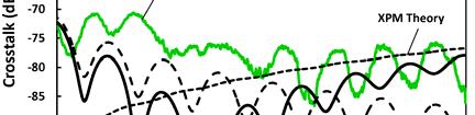
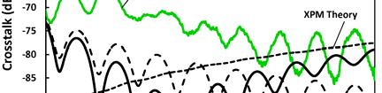
15 Fig. 8: Plot of crosstalk vs. frequency for multiple wavelengths. The dominance of the filter crosstalk is shown at lower frequencies covering the HF and VHF bands. 4 CROSSTALK MEASUREMENTS This section covers measured crosstalk data and its comparison to the theory developed in the previous section. The measurements were performed by using WDM filters to pass the active channel while the power from all other wavelengths was collected from the filter rejection port. Two filters in series were used in order to increase the rejection of the measurement system. Due to the properties of the filter the HF and VHF are bands dominated by the crosstalk of the filter itself. As can be seen in Fig. 8 there is a dramatic rise in the level of crosstalk at frequencies below 300 MHz. This rise cannot be physically described by SRS, XPM, or any other crosstalk mechanism. The data below show the complete set of crosstalk measurements including both SRS and XPM theory that was developed in previous sections, as well as the vector sum of both of those mechanisms. The parameters used for the calculations are shown in Table 1. While not all of the plots are equally instructive the full set has been included for archival purposes. As expected SRS crosstalk is the dominant mechanism for frequencies that are farther away from the modulated frequency while XPM dominates for small frequency differences as in the plot for 1553 or 1554nm. Of interest is the fact that the data match theory more closely for wavelengths that are longer than the modulated wavelength. Most likely this is due to the dispersion of the filter. In addition to this dispersion the mismatch between theory and experiment can be attributed to other mechanisms such as four wave mixing and various polarization effects. 10
16 Table 1. List of the parameters used to fit the data shown below. Variable Value Description ρ SRS 0.9 Polarization Overlap factor λ1 (nm) CW 1530 to1565 CW Laser wavelength λ2 (nm) Mod Modulated Laser Wavelength α (db/km) 0.2 Optical Fiber Propagation Loss L (km) 19.1 Fiber length P2 (dbm) 1.7 Aeff (um 2 ) 85 Fiber Effective Area D (ps/nm/km) 16.5 SMF 28e+ Dispersion gr (m/w) E 14 Raman Gain Coefficient d12 (ps/km) to See Eq. 10 Leff (km) Fiber Effective Length 11


17 12


18 13


19 14
20 5 SRS AND XPM IMPACT ON HF/VHF/UHF LINKS Based on the theory developed as well as the data collected and presented in the previous sections the effect of both SRS and XPM crosstalk can now be evaluated for HF/VHF/UHF photonic links and the systems that employ them. The results of such an analysis are presented in Fig. 9. For these data, the crosstalk due to SRS and XPM was calculated given the above equations and parameters, which assumes an ideal WDM filter. The maximum crosstalk level in each of the HF, VHF and UHF bands are shown in Fig. 9. Note that all of these levels are well below the dynamic range afforded by state-of-the-art analog fiber optic links for HF antenna remoting [1]. Fig. 9. Calculated maximum crosstalk as a function of wavelength for the HF, VHF and UHF bands. 15
21 6 CONCLUSIONS AND FURTHER CONSIDERATIONS This report has examined the theoretical expectations and experimental results of crosstalk due to Stimulated Raman Scattering and Cross Phase Modulation in HF/VHF/UHF photonic links. Using the equations for SRS and XPM the best case was calculated for each of the three bands under the constraint of a two wavelength system. Given the results presented in this report maintaining the dynamic range of the photonic links will be quite difficult. This will prove especially true for the HF/VHF bands where it would be desirable to avoid the filter dominated crosstalk shown here. If a WDM system is to be deployed in the future careful and thorough analysis and testing of the filters considered for deployment should be undergone before a final system architecture is selected. In addition to an analysis of filter crosstalk there are several other processes that could be considered for research in order to more full characterize and gain a better understanding of the complicated interactions in long fiber lengths within the bands of interest. Among these are XPM being converted to intensity modulation due to the dispersion of the WDM filter and an in depth examination of the effects of four wave mixing which was briefly discussed in this report. Also to be considered are the effects of multiple wavelengths interacting with each other. In addition to crosstalk effects there are a number of optical processes that can result in RF distortions. These include, FWM, polarization mode dispersion, and chromatic dispersion. The later of these can be easily corrected by using dispersion compensating fiber however the use of this fiber can have a deleterious effect on crosstalk. Also for long haul links that employ optical amplifiers the RF distortion due to these amplifiers must be considered as well. 16
22 REFERENCES [1] Urick, V. J., Diehl, J., Hastings, A., Sunderman, C., McKinney, J. D., Devgan, P. S., Dexter, J. L., and Williams, K. J., Analysis of fiber-optic links for HF antenna remoting, NRL Memorandum Report, NRL/MR/ (2008). [2] Urick, V. J., Hastings, A., Sunderman, C., Diehl, J., Colladay, K., Dexter, J. L., Williams, K. J., Field test on the feasibility of remoting HF antenna with fiber optics, NRL Memorandum Report, NRL/MR/ (2008). [3] Urick, V. J., Colladay, K. R., Sunderman, C. E., Diehl, J. F., Devgan, P. S., and Williams, K. J., Extended-distance analog fiber-optic links for HF antenna remoting, internal NRL Report (2009). [4] Agrawal, G., Nonlinear Fiber Optics, 5th edition, Academic Press (2013). [5] Campillo, A. L. and Bucholtz, F., Increased nonlinear crosstalk in analog wavelengthdivision-multiplexed links due to the chromatic dispersion of optical filters, IEEE Photonics Technology Lett., 18(19), (2006). [6] Wan, P. and Conradi, J., Impact of double Rayleigh backscatter noise on digital and analog fiber systems, J. of Lightwave Technol., 14(3), (1996). [7] Smith, R. G., Optical power handling capacity of low loss optical fibers as determined by stimulated Raman and Brillouin scattering, Applied Optics, 11(11), (1972). [8] Stolen, R. H. and Ippen, E. P., Raman gain in glass optical waveguides, Applied Physics Lett., 22(6), (1973). [9] Phillips, M. R. and Ott, D. M., Crosstalk due to optical fiber nonlinearities in WDM CATV lightwave systems, J. of Lightwave Technology, 17(10), (1999). [10] Campillo, A. L., Funk, E. E., Tulchinsky, D. A., Dexter, J. L., and Williams, K. J., Phase performance of an eight-channel wavelength-division-multiplexed analog-delay line, J. of Lightwave Technology, 22(2), (2004). [11] Antona, J. C., Bigo, S., and Kosmalski, S., Nonlinear index measurements of various fibre types over C+L bands using four-wave mixing, in Proc. 27th European Conf. on Optical Communications, (2001). [12] Phillips, M. R., Darcie, T. E., Marcuse, D., Bodeep, G. E., and Frigo, N. J., Nonlinear distortion generated by dispersive transmission of chirped intensity-modulated signals, IEEE Photonics Technology Lett., 3, (1991). [13] Marks, B. S., Menyuk, C. R., Campillo, A. L., and Bucholtz, F., Analysis of interchannel crosstalk in a dispersion-managed analog transmission link, J. of Lightwave Technology, 24(6), (2006). 17
Frequency Dependent Harmonic Powers in a Modified Uni-Traveling Carrier (MUTC) Photodetector
 Photodetector") Naval Research Laboratory Washington, DC 2375-532 NRL/MR/5651--17-9712 Frequency Dependent Harmonic Powers in a Modified Uni-Traveling Carrier (MUTC) Photodetector Yue Hu University of Maryland Baltimore,
Naval Research Laboratory Washington, DC 2375-532 NRL/MR/5651--17-9712 Frequency Dependent Harmonic Powers in a Modified Uni-Traveling Carrier (MUTC) Photodetector Yue Hu University of Maryland Baltimore,
Analysis of Photonic Phase-Shifting Technique Employing Amplitude- Controlled Fiber-Optic Delay Lines
 Naval Research Laboratory Washington, DC 20375-5320 NRL/MR/5650--12-9376 Analysis of Photonic Phase-Shifting Technique Employing Amplitude- Controlled Fiber-Optic Delay Lines Meredith N. Draa Vincent J.
Characteristics of an Optical Delay Line for Radar Testing
 Naval Research Laboratory Washington, DC 20375-5320 NRL/MR/5306--16-9654 Characteristics of an Optical Delay Line for Radar Testing Mai T. Ngo AEGIS Coordinator Office Radar Division Jimmy Alatishe SukomalTalapatra
Comparison of the Noise Penalty of a Raman Amplifier Versus an Erbium-doped Fiber Amplifier for Long-haul Analog Fiber-optic Links
 Naval Research Laboratory Washington, DC 0375-530 NRL/MR/5650--08-9167 Comparison of the Noise Penalty of a Raman Amplifier Versus an Erbium-doped Fiber Amplifier for Long-haul Analog Fiber-optic Links
Performance Limitations of WDM Optical Transmission System Due to Cross-Phase Modulation in Presence of Chromatic Dispersion
 Performance Limitations of WDM Optical Transmission System Due to Cross-Phase Modulation in Presence of Chromatic Dispersion M. A. Khayer Azad and M. S. Islam Institute of Information and Communication
Optical Communications and Networking 朱祖勍. Sept. 25, 2017
 Optical Communications and Networking Sept. 25, 2017 Lecture 4: Signal Propagation in Fiber 1 Nonlinear Effects The assumption of linearity may not always be valid. Nonlinear effects are all related to
Field Test on the Feasibility of Remoting HF Antenna with Fiber Optics
 Naval Research Laboratory Washington, DC 20375-5320 NRL/MR/5652--08-9137 Field Test on the Feasibility of Remoting HF Antenna with Fiber Optics Vincent J. Urick Alex Hastings James L. Dexter Keith J. Williams
Power penalty caused by Stimulated Raman Scattering in WDM Systems
 Paper Power penalty caused by Stimulated Raman Scattering in WDM Systems Sławomir Pietrzyk, Waldemar Szczęsny, and Marian Marciniak Abstract In this paper we present results of an investigation into the
Analysis of Self Phase Modulation Fiber nonlinearity in Optical Transmission System with Dispersion
 36 Analysis of Self Phase Modulation Fiber nonlinearity in Optical Transmission System with Dispersion Supreet Singh 1, Kulwinder Singh 2 1 Department of Electronics and Communication Engineering, Punjabi
Optical Fiber Technology. Photonic Network By Dr. M H Zaidi
 Optical Fiber Technology Numerical Aperture (NA) What is numerical aperture (NA)? Numerical aperture is the measure of the light gathering ability of optical fiber The higher the NA, the larger the core
INTRODUCTION. LPL App Note RF IN G 1 F 1. Laser Diode OPTICAL OUT. P out. Link Length. P in OPTICAL IN. Photodiode G 2 F 2 RF OUT
 INTRODUCTION RF IN Today s system designer may be faced with several technology choices for communications links for satellite microwave remoting, cellular/broadband services, or distribution of microwave
LINEAR MICROWAVE FIBER OPTIC LINK SYSTEM DESIGN
 LINEAR MICROWAVE FIBER OPTIC LINK SYSTEM DESIGN John A. MacDonald and Allen Katz Linear Photonics, LLC Nami Lane, Suite 7C, Hamilton, NJ 869 69-584-5747 macdonald@linphotonics.com LINEAR PHOTONICS, LLC
UNIT-II : SIGNAL DEGRADATION IN OPTICAL FIBERS
 UNIT-II : SIGNAL DEGRADATION IN OPTICAL FIBERS The Signal Transmitting through the fiber is degraded by two mechanisms. i) Attenuation ii) Dispersion Both are important to determine the transmission characteristics
Practical Aspects of Raman Amplifier
 Practical Aspects of Raman Amplifier Contents Introduction Background Information Common Types of Raman Amplifiers Principle Theory of Raman Gain Noise Sources Related Information Introduction This document
PH-7. Understanding of FWM Behavior in 2-D Time-Spreading Wavelength- Hopping OCDMA Systems. Abstract. Taher M. Bazan Egyptian Armed Forces
 PH-7 Understanding of FWM Behavior in 2-D Time-Spreading Wavelength- Hopping OCDMA Systems Taher M. Bazan Egyptian Armed Forces Abstract The behavior of four-wave mixing (FWM) in 2-D time-spreading wavelength-hopping
Experimental Observation of RF Radiation Generated by an Explosively Driven Voltage Generator
 Naval Research Laboratory Washington, DC 20375-5320 NRL/FR/5745--05-10,112 Experimental Observation of RF Radiation Generated by an Explosively Driven Voltage Generator MARK S. RADER CAROL SULLIVAN TIM
Spectral Response of FWM in EDFA for Long-haul Optical Communication
 Spectral Response of FWM in EDFA for Long-haul Optical Communication Lekshmi.S.R 1, Sindhu.N 2 1 P.G.Scholar, Govt. Engineering College, Wayanad, Kerala, India 2 Assistant Professor, Govt. Engineering
International Journal Of Scientific Research And Education Volume 3 Issue 4 Pages April-2015 ISSN (e): Website:
: Website:") International Journal Of Scientific Research And Education Volume 3 Issue 4 Pages-3183-3188 April-2015 ISSN (e): 2321-7545 Website: http://ijsae.in Effects of Four Wave Mixing (FWM) on Optical Fiber in
International Journal Of Scientific Research And Education Volume 3 Issue 4 Pages-3183-3188 April-2015 ISSN (e): 2321-7545 Website: http://ijsae.in Effects of Four Wave Mixing (FWM) on Optical Fiber in
Measurement of Chromatic Dispersion using the Baseband Radio-Frequency Response of a Phase-Modulated Analog Optical Link Employing a Reference Fiber
 Naval Research Laboratory Washington, DC 20375-5320 NRL/MR/5652--07-9072 Measurement of Chromatic Dispersion using the Baseband Radio-Frequency Response of a Phase-Modulated Analog Optical Link Employing
Signal Conditioning Parameters for OOFDM System
 Chapter 4 Signal Conditioning Parameters for OOFDM System 4.1 Introduction The idea of SDR has been proposed for wireless transmission in 1980. Instead of relying on dedicated hardware, the network has
DISTRIBUTION A: Distribution approved for public release.
 AFRL-OSR-VA-TR-2014-0205 Optical Materials PARAS PRASAD RESEARCH FOUNDATION OF STATE UNIVERSITY OF NEW YORK THE 05/30/2014 Final Report DISTRIBUTION A: Distribution approved for public release. Air Force
SCTE. San Diego Chapter March 19, 2014
 SCTE San Diego Chapter March 19, 2014 RFOG WHAT IS RFOG? WHY AND WHERE IS THIS TECHNOLOGY A CONSIDERATION? RFoG could be considered the deepest fiber version of HFC RFoG pushes fiber to the side of the
Ph.D. Course Spring Wireless Communications. Wirebound Communications
 Ph.D. Course Spring 2005 Danyo Danev associate professor Div. Data Transmission, Dept. Electrical Engineering Linköping University SWEDEN Wireless Communications Radio transmissions Mobile telephony Satellite
Analyzing the Non-Linear Effects in DWDM Optical Network Using MDRZ Modulation Format
 Analyzing the Non-Linear Effects in DWDM Optical Network Using MDRZ Modulation Format Ami R. Lavingia Electronics & Communication Dept. SAL Institute of Technology & Engineering Research Gujarat Technological
S Optical Networks Course Lecture 4: Transmission System Engineering
 S-72.3340 Optical Networks Course Lecture 4: Transmission System Engineering Edward Mutafungwa Communications Laboratory, Helsinki University of Technology, P. O. Box 2300, FIN-02015 TKK, Finland Tel:
8 10 Gbps optical system with DCF and EDFA for different channel spacing
 Research Article International Journal of Advanced Computer Research, Vol 6(24) ISSN (Print): 2249-7277 ISSN (Online): 2277-7970 http://dx.doi.org/10.19101/ijacr.2016.624002 8 10 Gbps optical system with
Table 10.2 Sensitivity of asynchronous receivers. Modulation Format Bit-Error Rate N p. 1 2 FSK heterodyne. ASK heterodyne. exp( ηn p /2) 40 40
 40 40") 10.5. SENSITIVITY DEGRADATION 497 Table 10.2 Sensitivity of asynchronous receivers Modulation Format Bit-Error Rate N p N p ASK heterodyne 1 2 exp( ηn p /4) 80 40 FSK heterodyne 1 2 exp( ηn p /2) 40 40
10.5. SENSITIVITY DEGRADATION 497 Table 10.2 Sensitivity of asynchronous receivers Modulation Format Bit-Error Rate N p N p ASK heterodyne 1 2 exp( ηn p /4) 80 40 FSK heterodyne 1 2 exp( ηn p /2) 40 40
Optical systems have carrier frequencies of ~100 THz. This corresponds to wavelengths from µm.
 Introduction A communication system transmits information form one place to another. This could be from one building to another or across the ocean(s). Many systems use an EM carrier wave to transmit information.
FIBER OPTICS. Prof. R.K. Shevgaonkar. Department of Electrical Engineering. Indian Institute of Technology, Bombay. Lecture: 37
 FIBER OPTICS Prof. R.K. Shevgaonkar Department of Electrical Engineering Indian Institute of Technology, Bombay Lecture: 37 Introduction to Raman Amplifiers Fiber Optics, Prof. R.K. Shevgaonkar, Dept.
IREAP. MURI 2001 Review. John Rodgers, T. M. Firestone,V. L. Granatstein, M. Walter
 MURI 2001 Review Experimental Study of EMP Upset Mechanisms in Analog and Digital Circuits John Rodgers, T. M. Firestone,V. L. Granatstein, M. Walter Institute for Research in Electronics and Applied Physics
EE 233. LIGHTWAVE. Chapter 2. Optical Fibers. Instructor: Ivan P. Kaminow
 EE 233. LIGHTWAVE SYSTEMS Chapter 2. Optical Fibers Instructor: Ivan P. Kaminow PLANAR WAVEGUIDE (RAY PICTURE) Agrawal (2004) Kogelnik PLANAR WAVEGUIDE a = (n s 2 - n c2 )/ (n f 2 - n s2 ) = asymmetry;
The absorption of the light may be intrinsic or extrinsic
 Attenuation Fiber Attenuation Types 1- Material Absorption losses 2- Intrinsic Absorption 3- Extrinsic Absorption 4- Scattering losses (Linear and nonlinear) 5- Bending Losses (Micro & Macro) Material
Non-Data Aided Doppler Shift Estimation for Underwater Acoustic Communication
 Non-Data Aided Doppler Shift Estimation for Underwater Acoustic Communication (Invited paper) Paul Cotae (Corresponding author) 1,*, Suresh Regmi 1, Ira S. Moskowitz 2 1 University of the District of Columbia,
Investigation of Modulated Laser Techniques for Improved Underwater Imaging
 Investigation of Modulated Laser Techniques for Improved Underwater Imaging Linda J. Mullen NAVAIR, EO and Special Mission Sensors Division 4.5.6, Building 2185 Suite 1100-A3, 22347 Cedar Point Road Unit
Frequency Stabilization Using Matched Fabry-Perots as References
 April 1991 LIDS-P-2032 Frequency Stabilization Using Matched s as References Peter C. Li and Pierre A. Humblet Massachusetts Institute of Technology Laboratory for Information and Decision Systems Cambridge,
All-Optical Signal Processing and Optical Regeneration
 1/36 All-Optical Signal Processing and Optical Regeneration Govind P. Agrawal Institute of Optics University of Rochester Rochester, NY 14627 c 2007 G. P. Agrawal Outline Introduction Major Nonlinear Effects
PSEUDO-RANDOM CODE CORRELATOR TIMING ERRORS DUE TO MULTIPLE REFLECTIONS IN TRANSMISSION LINES
 30th Annual Precise Time and Time Interval (PTTI) Meeting PSEUDO-RANDOM CODE CORRELATOR TIMING ERRORS DUE TO MULTIPLE REFLECTIONS IN TRANSMISSION LINES F. G. Ascarrunz*, T. E. Parkert, and S. R. Jeffertst
Suppression of Stimulated Brillouin Scattering
 Suppression of Stimulated Brillouin Scattering 42 2 5 W i de l y T u n a b l e L a s e r T ra n s m i t te r www.lumentum.com Technical Note Introduction This technical note discusses the phenomenon and
Vestigial Side Band Demultiplexing for High Spectral Efficiency WDM Systems
 The University of Kansas Technical Report Vestigial Side Band Demultiplexing for High Spectral Efficiency WDM Systems Chidambaram Pavanasam and Kenneth Demarest ITTC-FY4-TR-737- March 4 Project Sponsor:
Suppression of Four Wave Mixing Based on the Pairing Combinations of Differently Linear-Polarized Optical Signals in WDM System
 The Quarterly Journal of Optoelectronical Nanostructures Islamic Azad University Spring 2016 / Vol. 1, No.1 Suppression of Four Wave Mixing Based on the Pairing Combinations of Differently Linear-Polarized
High Performance Dispersion and Dispersion Slope Compensating Fiber Modules for Non-zero Dispersion Shifted Fibers
 High Performance Dispersion and Dispersion Slope Compensating Fiber Modules for Non-zero Dispersion Shifted Fibers Kazuhiko Aikawa, Ryuji Suzuki, Shogo Shimizu, Kazunari Suzuki, Masato Kenmotsu, Masakazu
Optical Transport Tutorial
 Optical Transport Tutorial 4 February 2015 2015 OpticalCloudInfra Proprietary 1 Content Optical Transport Basics Assessment of Optical Communication Quality Bit Error Rate and Q Factor Wavelength Division
MINIATURIZED ANTENNAS FOR COMPACT SOLDIER COMBAT SYSTEMS
 MINIATURIZED ANTENNAS FOR COMPACT SOLDIER COMBAT SYSTEMS Iftekhar O. Mirza 1*, Shouyuan Shi 1, Christian Fazi 2, Joseph N. Mait 2, and Dennis W. Prather 1 1 Department of Electrical and Computer Engineering
Lecture 8 Fiber Optical Communication Lecture 8, Slide 1
 Lecture 8 Bit error rate The Q value Receiver sensitivity Sensitivity degradation Extinction ratio RIN Timing jitter Chirp Forward error correction Fiber Optical Communication Lecture 8, Slide Bit error
Performance Analysis of Designing a Hybrid Optical Amplifier (HOA) for 32 DWDM Channels in L-band by using EDFA and Raman Amplifier
 for 32 DWDM Channels in L-band by using EDFA and Raman Amplifier") Performance Analysis of Designing a Hybrid Optical Amplifier (HOA) for 32 DWDM Channels in L-band by using EDFA and Raman Amplifier Aied K. Mohammed, PhD Department of Electrical Engineering, University
Performance Analysis of Designing a Hybrid Optical Amplifier (HOA) for 32 DWDM Channels in L-band by using EDFA and Raman Amplifier Aied K. Mohammed, PhD Department of Electrical Engineering, University
Dr. Monir Hossen ECE, KUET
 Dr. Monir Hossen ECE, KUET 1 Outlines of the Class Principles of WDM DWDM, CWDM, Bidirectional WDM Components of WDM AWG, filter Problems with WDM Four-wave mixing Stimulated Brillouin scattering WDM Network
REPORT DOCUMENTATION PAGE
 REPORT DOCUMENTATION PAGE Form Approved OMB No. 0704-0188 Public reporting burden for this collection of information is estimated to average 1 hour per response, including the time for reviewing instructions,
RZ BASED DISPERSION COMPENSATION TECHNIQUE IN DWDM SYSTEM FOR BROADBAND SPECTRUM
 RZ BASED DISPERSION COMPENSATION TECHNIQUE IN DWDM SYSTEM FOR BROADBAND SPECTRUM Prof. Muthumani 1, Mr. Ayyanar 2 1 Professor and HOD, 2 UG Student, Department of Electronics and Communication Engineering,
Lecture 3 Fiber Optical Communication Lecture 3, Slide 1
 Lecture 3 Dispersion in single-mode fibers Material dispersion Waveguide dispersion Limitations from dispersion Propagation equations Gaussian pulse broadening Bit-rate limitations Fiber losses Fiber Optical
Investigating a Simulated Model of 2.5 GHz 64 Channel 140 kmdwdm System Using EDFAand Raman Amplifier Considering Self-Phase Modulation
 IOSR Journal of Electronics and Communication Engineering (IOSR-JECE) e-issn: 2278-2834,p- ISSN: 2278-8735.Volume 10, Issue 1, Ver. III (Jan - Feb. 2015), PP 91-95 www.iosrjournals.org Investigating a
Ship echo discrimination in HF radar sea-clutter
 Ship echo discrimination in HF radar sea-clutter A. Bourdillon (), P. Dorey () and G. Auffray () () Université de Rennes, IETR/UMR CNRS 664, Rennes Cedex, France () ONERA, DEMR/RHF, Palaiseau, France.
Chapter 3 Signal Degradation in Optical Fibers
 What about the loss in optical fiber? Why and to what degree do optical signals gets distorted as they propagate along a fiber? Fiber links are limited by in path length by attenuation and pulse distortion.
REPORT DOCUMENTATION PAGE. A peer-to-peer non-line-of-sight localization system scheme in GPS-denied scenarios. Dr.
 REPORT DOCUMENTATION PAGE Form Approved OMB No. 0704-0188 The public reporting burden for this collection of information is estimated to average 1 hour per response, including the time for reviewing instructions,
Fiber-Optic Communication Systems
 Fiber-Optic Communication Systems Second Edition GOVIND P. AGRAWAL The Institute of Optics University of Rochester Rochester, NY A WILEY-iNTERSCIENCE PUBLICATION JOHN WILEY & SONS, INC. NEW YORK / CHICHESTER
Enabling technology for suppressing nonlinear interchannel crosstalk in DWDM transoceanic systems
 1/13 Enabling technology for suppressing nonlinear interchannel crosstalk in DWDM transoceanic systems H. Zhang R.B. Jander C. Davidson D. Kovsh, L. Liu A. Pilipetskii and N. Bergano April 2005 1/12 Main
Impact of Fiber Non-Linearities in Performance of Optical Communication
 Impact of Fiber Non-Linearities in Performance of Optical Communication Narender Kumar Sihval 1, Vivek Kumar Malik 2 M. Tech Students in ECE Department, DCRUST-Murthal, Sonipat, India Abstract: Non-linearity
OPTICAL NETWORKS. Building Blocks. A. Gençata İTÜ, Dept. Computer Engineering 2005
 OPTICAL NETWORKS Building Blocks A. Gençata İTÜ, Dept. Computer Engineering 2005 Introduction An introduction to WDM devices. optical fiber optical couplers optical receivers optical filters optical amplifiers
Final Report for AOARD Grant FA Indoor Localization and Positioning through Signal of Opportunities. Date: 14 th June 2013
 Final Report for AOARD Grant FA2386-11-1-4117 Indoor Localization and Positioning through Signal of Opportunities Date: 14 th June 2013 Name of Principal Investigators (PI and Co-PIs): Dr Law Choi Look
A New Scheme for Acoustical Tomography of the Ocean
 A New Scheme for Acoustical Tomography of the Ocean Alexander G. Voronovich NOAA/ERL/ETL, R/E/ET1 325 Broadway Boulder, CO 80303 phone (303)-497-6464 fax (303)-497-3577 email agv@etl.noaa.gov E.C. Shang
Optimization of supercontinuum generation in photonic crystal fibers for pulse compression
 Optimization of supercontinuum generation in photonic crystal fibers for pulse compression Noah Chang Herbert Winful,Ted Norris Center for Ultrafast Optical Science University of Michigan What is Photonic
Network Challenges for Coherent Systems. Mike Harrop Technical Sales Engineering, EXFO
 Network Challenges for Coherent Systems Mike Harrop Technical Sales Engineering, EXFO Agenda 1. 100G Transmission Technology 2. Non Linear effects 3. RAMAN Amplification 1. Optimsing gain 2. Keeping It
Optical Amplifiers Photonics and Integrated Optics (ELEC-E3240) Zhipei Sun Photonics Group Department of Micro- and Nanosciences Aalto University
 Zhipei Sun Photonics Group Department of Micro- and Nanosciences Aalto University") Photonics Group Department of Micro- and Nanosciences Aalto University Optical Amplifiers Photonics and Integrated Optics (ELEC-E3240) Zhipei Sun Last Lecture Topics Course introduction Ray optics & optical
Photonics Group Department of Micro- and Nanosciences Aalto University Optical Amplifiers Photonics and Integrated Optics (ELEC-E3240) Zhipei Sun Last Lecture Topics Course introduction Ray optics & optical
CSO/CTB PERFORMANCE IMPROVEMENT BY USING FABRY-PEROT ETALON AT THE RECEIVING SITE
 Progress In Electromagnetics Research Letters, Vol. 6, 107 113, 2009 CSO/CTB PERFORMANCE IMPROVEMENT BY USING FABRY-PEROT ETALON AT THE RECEIVING SITE S.-J. Tzeng, H.-H. Lu, C.-Y. Li, K.-H. Chang,and C.-H.
AFRL-RY-WP-TR
 AFRL-RY-WP-TR-2017-0158 SIGNAL IDENTIFICATION AND ISOLATION UTILIZING RADIO FREQUENCY PHOTONICS Preetpaul S. Devgan RF/EO Subsystems Branch Aerospace Components & Subsystems Division SEPTEMBER 2017 Final
WDM Concept and Components. EE 8114 Course Notes
 WDM Concept and Components EE 8114 Course Notes Part 1: WDM Concept Evolution of the Technology Why WDM? Capacity upgrade of existing fiber networks (without adding fibers) Transparency:Each optical channel
Wavelength Division Multiplexing (WDM) Technology for Naval Air Applications
 Technology for Naval Air Applications") Wavelength Division Multiplexing (WDM) Technology for Naval Air Applications Drew Glista Naval Air Systems Command Patuxent River, MD glistaas@navair.navy.mil 301-342-2046 1 Report Documentation Page Form
Wavelength Division Multiplexing (WDM) Technology for Naval Air Applications Drew Glista Naval Air Systems Command Patuxent River, MD glistaas@navair.navy.mil 301-342-2046 1 Report Documentation Page Form
Performance of Band-Partitioned Canceller for a Wideband Radar
 Naval Research Laboratory Washington, DC 20375-5320 NRL/MR/5340--04-8809 Performance of Band-Partitioned Canceller for a Wideband Radar FENG-LING C. LIN KARL GERLACH Surveillance Technology Branch Radar
REPORT DOCUMENTATION PAGE
 REPORT DOCUMENTATION PAGE Form Approved OMB NO. 0704-0188 The public reporting burden for this collection of information is estimated to average 1 hour per response, including the time for reviewing instructions,
CHAPTER 5 SPECTRAL EFFICIENCY IN DWDM
 61 CHAPTER 5 SPECTRAL EFFICIENCY IN DWDM 5.1 SPECTRAL EFFICIENCY IN DWDM Due to the ever-expanding Internet data traffic, telecommunication networks are witnessing a demand for high-speed data transfer.
Key Issues in Modulating Retroreflector Technology
 Key Issues in Modulating Retroreflector Technology Dr. G. Charmaine Gilbreath, Code 7120 Naval Research Laboratory 4555 Overlook Ave., NW Washington, DC 20375 phone: (202) 767-0170 fax: (202) 404-8894
International Journal of Engineering Research & Technology (IJERT) ISSN: Vol. 2 Issue 9, September
 ISSN: Vol. 2 Issue 9, September") Performance Enhancement of WDM-ROF Networks With SOA-MZI Shalu (M.Tech), Baljeet Kaur (Assistant Professor) Department of Electronics and Communication Guru Nanak Dev Engineering College, Ludhiana Abstract
Performance Enhancement of WDM-ROF Networks With SOA-MZI Shalu (M.Tech), Baljeet Kaur (Assistant Professor) Department of Electronics and Communication Guru Nanak Dev Engineering College, Ludhiana Abstract
Acoustic Measurements of Tiny Optically Active Bubbles in the Upper Ocean
 Acoustic Measurements of Tiny Optically Active Bubbles in the Upper Ocean Svein Vagle Ocean Sciences Division Institute of Ocean Sciences 9860 West Saanich Road P.O. Box 6000 Sidney, BC, V8L 4B2 Canada
Loop-Dipole Antenna Modeling using the FEKO code
 Loop-Dipole Antenna Modeling using the FEKO code Wendy L. Lippincott* Thomas Pickard Randy Nichols lippincott@nrl.navy.mil, Naval Research Lab., Code 8122, Wash., DC 237 ABSTRACT A study was done to optimize
Elimination of Self-Pulsations in Dual-Clad, Ytterbium-Doped Fiber Lasers
 Elimination of Self-Pulsations in Dual-Clad, Ytterbium-Doped Fiber Lasers 1.0 Modulation depth 0.8 0.6 0.4 0.2 0.0 Laser 3 Laser 2 Laser 4 2 3 4 5 6 7 8 Absorbed pump power (W) Laser 1 W. Guan and J. R.
Performance Analysis of Gb/s DWDM Metropolitan Area Network using SMF-28 and MetroCor Optical Fibres
 Research Cell: An International Journal of Engineering Sciences ISSN: 2229-6913 Issue Sept 2011, Vol. 4 11 Performance Analysis of 32 2.5 Gb/s DWDM Metropolitan Area Network using SMF-28 and MetroCor Optical
Nonlinear Effect of Four Wave Mixing for WDM in Radio-over-Fiber Systems
 Quest Journals Journal of Electronics and Communication Engineering Research Volume ~ Issue 4 (014) pp: 01-06 ISSN(Online) : 31-5941 www.questjournals.org Research Paper Nonlinear Effect of Four Wave Mixing
τ mod = T modal = longest ray path shortest ray path n 1 L 1 = L n 2 1
 S. Blair February 15, 2012 23 2.2. Pulse dispersion Pulse dispersion is the spreading of a pulse as it propagates down an optical fiber. Pulse spreading is an obvious detrimental effect that limits the
FOPA Pump Phase Modulation and Polarization Impact on Generation of Idler Components
 http://dx.doi.org/10.5755/j01.eie.22.4.15924 FOPA Pump Phase Modulation and Polarization Impact on Generation of Idler Components Sergejs Olonkins 1, Vjaceslavs Bobrovs 1, Girts Ivanovs 1 1 Institute of
Types of losses in optical fiber cable are: Due to attenuation, the power of light wave decreases exponentially with distance.
 UNIT-II TRANSMISSION CHARACTERISTICS OF OPTICAL FIBERS SIGNAL ATTENUATION: Signal attenuation in an optical fiber is defined as the decrease in light power during light propagation along an optical fiber.
Performance Analysis Of Hybrid Optical OFDM System With High Order Dispersion Compensation
 Performance Analysis Of Hybrid Optical OFDM System With High Order Dispersion Compensation Manpreet Singh Student, University College of Engineering, Punjabi University, Patiala, India. Abstract Orthogonal
Remote Sediment Property From Chirp Data Collected During ASIAEX
 Remote Sediment Property From Chirp Data Collected During ASIAEX Steven G. Schock Department of Ocean Engineering Florida Atlantic University Boca Raton, Fl. 33431-0991 phone: 561-297-3442 fax: 561-297-3885
Performance Evaluation of Hybrid (Raman+EDFA) Optical Amplifiers in Dense Wavelength Division Multiplexed Optical Transmission System
 Optical Amplifiers in Dense Wavelength Division Multiplexed Optical Transmission System") Performance Evaluation of Hybrid (Raman+EDFA) Optical Amplifiers in Dense Wavelength Division Multiplexed Optical Transmission System Gagandeep Singh Walia 1, Kulwinder Singh 2, Manjit Singh Bhamrah 3
Performance Evaluation of Hybrid (Raman+EDFA) Optical Amplifiers in Dense Wavelength Division Multiplexed Optical Transmission System Gagandeep Singh Walia 1, Kulwinder Singh 2, Manjit Singh Bhamrah 3
International Journal of Advanced Research in Computer Science and Software Engineering
 ISSN: 2277 128X International Journal of Advanced Research in Computer Science and Software Engineering Research Paper Available online at: Performance Analysis of WDM/SCM System Using EDFA Mukesh Kumar
Chirped Bragg Grating Dispersion Compensation in Dense Wavelength Division Multiplexing Optical Long-Haul Networks
 363 Chirped Bragg Grating Dispersion Compensation in Dense Wavelength Division Multiplexing Optical Long-Haul Networks CHAOUI Fahd 3, HAJAJI Anas 1, AGHZOUT Otman 2,4, CHAKKOUR Mounia 3, EL YAKHLOUFI Mounir
FWM Suppression in WDM Systems Using Advanced Modulation Formats
 FWM Suppression in WDM Systems Using Advanced Modulation Formats M.M. Ibrahim (eng.mohamed.ibrahim@gmail.com) and Moustafa H. Aly (drmosaly@gmail.com) OSA Member Arab Academy for Science, Technology and
Chapter 12: Optical Amplifiers: Erbium Doped Fiber Amplifiers (EDFAs)
") Chapter 12: Optical Amplifiers: Erbium Doped Fiber Amplifiers (EDFAs) Prof. Dr. Yaocheng SHI ( 时尧成 ) yaocheng@zju.edu.cn http://mypage.zju.edu.cn/yaocheng 1 Traditional Optical Communication System Loss
Chapter 12: Optical Amplifiers: Erbium Doped Fiber Amplifiers (EDFAs) Prof. Dr. Yaocheng SHI ( 时尧成 ) yaocheng@zju.edu.cn http://mypage.zju.edu.cn/yaocheng 1 Traditional Optical Communication System Loss
ANALYSIS OF DISPERSION COMPENSATION IN A SINGLE MODE OPTICAL FIBER COMMUNICATION SYSTEM
 ANAYSIS OF DISPERSION COMPENSATION IN A SINGE MODE OPTICA FIBER COMMUNICATION SYSTEM Sani Abdullahi Mohammed 1, Engr. Yahya Adamu and Engr. Matthew Kwatri uka 3 1,,3 Department of Electrical and Electronics
Faculty of Science, Art and Heritage, Universiti Tun Hussein Onn Malaysia, Batu Pahat, Johor, Malaysia.
 An All-Optical Frequency Up/Down-Converter Utilizing Stimulated Brillouin Scattering In A Trf And Dcf For Rof Application N. A. Awang 1,2, H. Ahmad 2, S. F. Norizan 2, M.Z. Zulkifli 2, Z.A.Ghani 4 and
EXPERIMENTAL STUDY OF SBS SUPPRESSION VIA WHITE NOISE PHASE MODULATION (POSTPRINT)
") AFRL-RD-PS- TP-2015-0008 AFRL-RD-PS- TP-2015-0008 EXPERIMENTAL STUDY OF SBS SUPPRESSION VIA WHITE NOISE PHASE MODULATION (POSTPRINT) Brian Anderson, et al. 10 February 2014 Technical Paper APPROVED FOR
AFRL-RD-PS- TP-2015-0008 AFRL-RD-PS- TP-2015-0008 EXPERIMENTAL STUDY OF SBS SUPPRESSION VIA WHITE NOISE PHASE MODULATION (POSTPRINT) Brian Anderson, et al. 10 February 2014 Technical Paper APPROVED FOR
Lecture 7 Fiber Optical Communication Lecture 7, Slide 1
 Dispersion management Lecture 7 Dispersion compensating fibers (DCF) Fiber Bragg gratings (FBG) Dispersion-equalizing filters Optical phase conjugation (OPC) Electronic dispersion compensation (EDC) Fiber
CROSS-PHASE modulation (XPM) has an important impact
 has an important impact") 1018 JOURNAL OF LIGHTWAVE TECHNOLOGY, VOL. 17, NO. 6, JUNE 1999 Cross-Phase Modulation in Multispan WDM Optical Fiber Systems Rongqing Hui, Senior Member, IEEE, Kenneth R. Demarest, Senior Member, IEEE,
1018 JOURNAL OF LIGHTWAVE TECHNOLOGY, VOL. 17, NO. 6, JUNE 1999 Cross-Phase Modulation in Multispan WDM Optical Fiber Systems Rongqing Hui, Senior Member, IEEE, Kenneth R. Demarest, Senior Member, IEEE,
Study of All-Optical Wavelength Conversion and Regeneration Subsystems for use in Wavelength Division Multiplexing (WDM) Telecommunication Networks.
 Telecommunication Networks.") Study of All-Optical Wavelength Conversion and Regeneration Subsystems for use in Wavelength Division Multiplexing (WDM) Telecommunication Networks. Hercules Simos * National and Kapodistrian University
Study of All-Optical Wavelength Conversion and Regeneration Subsystems for use in Wavelength Division Multiplexing (WDM) Telecommunication Networks. Hercules Simos * National and Kapodistrian University
Study of Multiwavelength Fiber Laser in a Highly Nonlinear Fiber
 Study of Multiwavelength Fiber Laser in a Highly Nonlinear Fiber I. H. M. Nadzar 1 and N. A.Awang 1* 1 Faculty of Science, Technology and Human Development, Universiti Tun Hussein Onn Malaysia, Johor,
Differential measurement scheme for Brillouin Optical Correlation Domain Analysis
 Differential measurement scheme for Brillouin Optical Correlation Domain Analysis Ji Ho Jeong, 1,2 Kwanil Lee, 1,4 Kwang Yong Song, 3,* Je-Myung Jeong, 2 and Sang Bae Lee 1 1 Center for Opto-Electronic
Optical Digital Transmission Systems. Xavier Fernando ADROIT Lab Ryerson University
 Optical Digital Transmission Systems Xavier Fernando ADROIT Lab Ryerson University Overview In this section we cover point-to-point digital transmission link design issues (Ch8): Link power budget calculations
Investigation of the impact of fiber Bragg grating bandwidth on the efficiency of a fiber Raman laser
 Investigation of the impact of fiber Bragg grating bandwidth on the efficiency of a fiber Raman laser US-Australia meeting May12, 2015 Leanne J. Henry, Michael Klopfer (1), and Ravi Jain (1) (1) University
Limits to the Exponential Advances in DWDM Filter Technology? Philip J. Anthony
 Limits to the Exponential Advances in DWDM Filter Technology? DARPA/MTO WDM for Military Platforms April 18-19, 2000 McLean, VA Philip J. Anthony E-TEK Dynamics San Jose CA phil.anthony@e-tek.com Report
Phase Modulator for Higher Order Dispersion Compensation in Optical OFDM System
 Phase Modulator for Higher Order Dispersion Compensation in Optical OFDM System Manpreet Singh 1, Karamjit Kaur 2 Student, University College of Engineering, Punjabi University, Patiala, India 1. Assistant
Acoustic Change Detection Using Sources of Opportunity
 Acoustic Change Detection Using Sources of Opportunity by Owen R. Wolfe and Geoffrey H. Goldman ARL-TN-0454 September 2011 Approved for public release; distribution unlimited. NOTICES Disclaimers The findings
EXAMINATION FOR THE DEGREE OF B.E. and M.E. Semester
 EXAMINATION FOR THE DEGREE OF B.E. and M.E. Semester 2 2009 101908 OPTICAL COMMUNICATION ENGINEERING (Elec Eng 4041) 105302 SPECIAL STUDIES IN MARINE ENGINEERING (Elec Eng 7072) Official Reading Time: