User Manual For David GNSS Receiver
|
|
|
- Millicent Reed
- 5 years ago
- Views:
Transcription


1 User Manual Version V User Manual For David GNSS Receiver 2018 Tersus GNSS Inc. All rights reserved. Sales & Technical Support: & More details, please visit
2 Table of Content 1. Overview Introduction Receiver Features Brief Introduction of GNSS and RTK Devices in David Package Rover Kit Mobile Mode David Receiver GNSS Antenna The 2pin-USB Power Cable COMM1-bluetooth Module Bracket for Rover GNSS Antenna Connector COMM2-7pin-USB & DB9 Data Cable Other accessories Rover Kit with 1W Radio Station RS900C 1W/915MHz Radio Rover Kit with 2W Radio Station RS400L2 2W/460MHz Radio Accessories Base Kit Mobile Mode Bracket for Base Tape Meter Base Kit with 1W Radio Station Base Kit with 2W Radio Station Accessories Base Kit with 30W Radio Station W Radio General operation Install the GNSS antenna Power on David / 83
3 3.3 Communication between Android phone and David With Wires With an External Bluetooth FW Upgrade & Auth code Firmware Updates Auth Code Download Files from Internal emmc Card Input command directly to the GNSS board Introduction of Nuwa Specification David Receiver ANTENNA AX W Radio RS900C W Radio RS400L W Radio RS400L Typical operating David as a Rover to receive corrections from Internet David as a Base to transmit corrections to Internet Radios Transmit RTK Corrections between Two Davids Data Collection for Post Processing Auto Base Station List Function Terminology / 83
4 List of Figures Figure 1 Outlook of David GNSS receiver... 8 Figure 2 Outline of David System... 9 Figure 3 Corrections transmitted via Internet Figure 4 Corrections transmitted with radios Figure 5 David in the box Figure 6 Field photo Figure 7 Field photo Figure 8 David Receiver Figure 9 AX3702 antenna Figure 10 RF cable Figure 11 2pin-USB Power Cable Figure 12 Bluetooth Module Figure 13 Bracket for Rover Figure 14 GNSS Antenna Connector Figure 15 COMM2-7pin-USB & DB9 Data Cable Figure 16 USB Type A Male to DB9 Male cable Figure 17 USB Type A Female to USB (Micro + Type C) OTG cable Figure 18 Height Measure Accessory Figure 19 Battery Bank Figure 20 Field Photo Figure 21 Field Photo Figure 22 RS900C 1W Radio Station Figure 23 Field Photo Figure 24 Field Photo Figure 25 2W /460MHz Radio Figure 26 COMM2-7pin-USB & 5pin Cable Figure 27 TNC-J/TNC-J cable 1.0M Figure 28 TNC - TNC converter & Bracket for 460M antenna Figure 29 Field Photo Figure 30 Bracket for Base Figure 31 Tape Meter Figure 32 Field Photo Figure 33 Field photo Figure 34 Field Photo Figure 35 2pin-Bullet DC CON Cable Figure 36 Power cable for 30W radio Figure 37 Hook and Screws for David Figure 38 Hook and Screws for 2W Radio Figure 39 Bracket for Mobile Figure 40 30W Radio Antenna Figure 41 Telescopic Pole for Radio Antenna Figure 42 Field Photo Figure 43 Field Photo / 83
5 Figure 44 30W Radio Station Figure 45 COMM cable for 30W radio Figure 46 Outline of Android phone to David with Wires Figure 47 Outline of Android phone to David with Bluetooth Figure 48 Outline of David connected to a Computer Figure 49 Download file from emmc card Figure 50 Booting up page Figure 51 Four Main Windows of Nuwa Figure 52 Panel of David Figure 53 Pin Definition of the COMM1/COMM2/DC ports Figure 54 Outline of Android phone to David with Wire Figure 55 Outline of Android phone to David with Wire Figure 56 Outline of Base/Rover with Radios Figure 57 Outline of Static Data Collection / 83
6 List of Tables Table 1 The document / software used in this user manual... 6 Table 2 Seven David Variants Table 3 Devices in rover mobile mode Table 4 Definition of LEDs Table 5 Functions of COMM2-7pin-USB & DB9 Data Cable Table 6 Rover Kit with 1W Radio Station Table 7 LED Definition Table 8 Rover Kit with 2W Radio Station Table 9 Button Manual Table 10 LED Definition Table 11 Base Kit Mobile Mode Table 12 Base Kit with 1W Radio Station Table 13 Base Kit with 2W Radio Station Table 14 Base Kit with 30W Radio Station Table 15 The Definition of the Control Buttons Table 16 Definition of LEDs Table 17 Detailed steps Table 18 Detailed steps Table 19 Preparation for FW update Table 20 Detailed Steps for FW update Table 21 Detailed Steps to download files from emmc card Table 22 Input commands to the BX306 directly Table 23 David GNSS Performance Table 24 Pin Definition Table 25 Antenna AX Table 26 Specification for RS900C Table 27 Specification for RS400L Table 28 RS400L30 Radio Specification Table 29 Detailed steps for rover receive corrections from Internet Table 30 Detailed steps for Base transmit corrections to Internet Table 31 Detailed steps for David with Radios Table 32 Detailed Steps for Static Data Collection Table 33 List of terminology / 83
7 Notices The following notices apply to DAVID receiver. Changes or modifications to this equipment not expressly approved by Tersus could void the user s authority to operate this equipment or even has risk to damage the DAVID. Conventions The following conventions are used in this manual:! Information that supplements or clarifies text. A caution that actions, operation or configuration may lead to incorrect or improper use of the hardware. A warning that actions, operation or configuration may result in regulatory noncompliance, safety issues or equipment damage. NUWA is Tersus survey app, four tabs (Project, Device, Survey and Tools) are provided in the Nuwa main window. So, in chapter 0, all the operations in the Survey software will start from these four tabs. In all the figures, a line with two arrows at the two sides means it s a cable. A line with one arrow gives the installation direction. Table 1 The document / software used in this user manual Name Description Link Log & Command document Tersus GNSS Center Nuwa Tersus Geomatics Office Document giving all the loggings output from David and all the commands to David Graphical tool to communicate with David Survey application running in the Android platform, David can be configured with Nuwa. Post processing tool for static data ets/upload/file/ pdf ets/upload/file/ zip ets/upload/file/ rar 6 / 83
8 TersusDownload A tool to download files on emmc card ets/upload/file/ zip Support If you have a problem and cannot find the information you need in the product documentation, request technical support using the Tersus website at or mail to support@tersus-gnss.com 7 / 83

9 1. Overview 1.1 Introduction Tersus DAVID is a cost-efficient, palm-sized GNSS receiver, mainly for the mass survey market, but also for UAV/AGV/Agriculture application. Nuwa, a survey App on Android system, is working with David, which can communicate with an Android platform such as a phone or tablet via USB cable or an external Bluetooth module. The David can work as a base or a rover, it can support real-time RTK positioning as well as saving data for PPK application. Up to 4GB on-board EMMC card makes it easy to save data for PPK. The RS-232 serial port, IP67 standard and the external Bluetooth module can remove most of the inconvenience for field workers. All the operating can be done in the App Nuwa except downloading raw measurement data file, which will be done with Tersus GNSS Center, see Table 1 and section 3.5 Download Files from Internal emmc Card for detail. Figure 1 Outlook of David GNSS receiver 1.2 Receiver Features Supports GPS L1/L2, BDS B1/B2 and GLONASS G1/G2. Support RTCM2.3/3.x, CMR, CMR+ corrections. 8 / 83
10 Easy to connect an external powerful radio for longer range. Solution rate can be 5Hz. 20Hz raw measurements output for post processing. The accuracy of carrier phase can be 1mm. On-board 4GB emmc card for data collection Static post-processing for mm-level accuracy. Bluetooth module makes wireless connection. Input power range is 5-12V, connect to battery bank directly. IP67 for water & dust proof, work reliably in harsh condition The Lemo connectors support mis-installation avoidance. 1.3 Brief Introduction of GNSS and RTK Tersus BX306 GNSS receiver is integrated in David, the board is receiving the GNSS signals from satellites and RTK corrections from the base, and is outputting cm-level position, velocity and time. Figure 2 shows David system; see for more about BX306 receiver. Figure 2 Outline of David System 9 / 83
11 The RTK corrections are transmitted from a base, which can be a CORS station or a David receiver. The RTK corrections can be transmitted to the rover via Internet or with external radios. Figure 3 Corrections transmitted via Internet Figure 4 Corrections transmitted with radios If RTK corrections are transmitted via Internet, an Android phone will be included in the RTK system to transmit/receive the RTK corrections, see section 6.1 and section 6.2 for detailed operating. 10 / 83

12 2. Devices in David Package This chapter will give detailed introduction about all the devices in the package. David has seven variants, which are convenient for customers to select per their application. Different accessories are included in each variant. Table 2 gives a brief description of the seven variants. For more about them, refer to section 2.1 to section 2.7. All the seven variants are shipped in a plastic box in Figure 5. Figure 5 David in the box Table 2 Seven David Variants David variants Description Rover Kit Mobile The David receiver will receive RTK corrections from a Mode NTRIP caster or a TCP server. Rover Kit with 1W The David receiver will receive RTK corrections from an Radio Station external 1W 915Mhz radios. Rover Kit with 2W The David receiver will receive RTK corrections from an Radio Station external 2W 460MHz radios. Base Kit Mobile The David receiver will output RTK corrections to a Mode NTRIP caster or a TCP server. Base Kit with 1W The David receiver will output RTK corrections to an Radio Station external 1W 915Mhz radio. 11 / 83
13 Base Kit with 2W Radio Station Base Kit with 30W Radio Station The David receiver will output RTK corrections to an external 2W 460MHz radio. The David receiver will output RTK corrections to an external 30W 460MHz radio.! 1. Rover Kit Mobile Mode and Base Kit Mobile Mode can work independently. 2. Rover Kit with 1W Radio Station must work with Base Kit with 1W Radio Station. 3. Rover Kit with 2W Radio Station must work with Base Kit with 2W Radio Station or Base Kit with 30W Radio Station. 2.1 Rover Kit Mobile Mode In this variant, the David will be connected to an Android phone with Bluetooth module or with cables. Tersus Survey Nuwa App will run in the Android phone to receive RTK corrections from a NTRIP caster or a TCP server. Refer to section 6.1 for detailed operation Figure 6 Field photo / 83

14 Figure 7 Field photo 1-2 8! The power bank in Figure 7 is not included in the package. Table 3 Devices in rover mobile mode Devices Number Items in the field photos David GNSS receiver 1 5 GNSS antenna 1 1 GNSS antenna connector 1 Not in the field photo, refer to section for detail. GNSS antenna cable 1 3 2pin-USB power cable 1 8, see Figure 11 COMM1-Bluetooth module 1 6, refer to COMM2-7pin-USB & DB9 Data cable 1 Not in the field photo, refer to section USB Type A Female to USB(Micro + Not in the field photo, refer 1 Type C) OTG cable to Figure 17 USB Type A Male to DB9 Male cable 1 Not in the field photo, refer to Figure 16 Ranging pole 1 2 Height measure accessory 1 Not in the field photo, See Figure 18. Bracket for rover 1 4, see section Battery bank 1 7, see Figure 19 and 3.2 Power on David 13 / 83

15 2.1.1 David Receiver David has four interfaces, see Figure 8 David Receiver. Antenna input COMM1 port COMM2 port DC port Figure 8 David Receiver David s DC is for power input, COMM1 port is for COM1 and CAN ports, and COMM2 port is for COM2 and USB ports, see chapter 5 for detail. Table 4 Definition of LEDs LED Colour Description PWR RED ON: the David is power on. PV BLUE ON: David in Fixed solution. Blink: David in Float solution OFF: David in other position types. Please see section 3.2 Power on David for more about the booting up procedure. Refer to Chapter 5 for the specification of David receiver and the detailed definition of COMM1, COMM2 and DC ports GNSS Antenna GNSS antenna is used to receive the RF signal from the satellites. AX3702 is provided in the package, which must be connected to the David with the RF cable in the package. 14 / 83


16 Figure 9 AX3702 antenna If an antenna from other companies will be used, contact Tersus to get permission, or the David may not work as it s expected. Figure 10 RF cable The 2pin-USB Power Cable The power cable is used to connect a battery bank to the DC port of David. 15 / 83


17 Figure 11 2pin-USB Power Cable COMM1-bluetooth Module This Bluetooth module will use the COM1 port of David. Figure 12 Bluetooth Module The Bluetooth can only be installed to the COMM1 port of David. The SSID for this Bluetooth module is BT420A-xxxxx_xxxxxx, where the first xxxxx is the last 5 digits of the Bluetooth serial number, which is printed on the Bluetooth module. No password is needed to pair with it Bracket for Rover Bracket for rover is used to fix all the devices on the ranging pole, which bring much convenience to field staffs. 16 / 83


18 Figure 13 Bracket for Rover GNSS Antenna Connector The GNSS antenna connector is used to install the GNSS antenna or the 30W radio station antenna to a tripod. Figure 14 GNSS Antenna Connector COMM2-7pin-USB & DB9 Data Cable The COMM2-7pin-USB & DB9 Data Cable has three functions: 17 / 83
 to download file saved on the internal emmc card, refer to section 3.5 Download Files from Internal emmc Card; 3.")

19 Table 5 Functions of COMM2-7pin-USB & DB9 Data Cable 1. Connect to an external 1W radio module. 2. Connect to USB Type A Male to DB9 Male cable (see Figure 16) to download file saved on the internal emmc card, refer to section 3.5 Download Files from Internal emmc Card; 3. Connect to USB Type A Female to USB (Micro +Type C) OTG cable (see Figure 17) to connect the Android phone with David, refer to section Figure 15 COMM2-7pin-USB & DB9 Data Cable! The COMM2-7pin-USB cable can only be installed into the COMM2 port of David Other accessories USB Type A Male to DB9 Data cable, USB Type A Female to USB (Micro + Type C) OTG cable and Height Measure Accessory are included in this variant. Figure 16 USB Type A Male to DB9 Male cable The driver for the cable above can be downloaded 18 / 83


20 Figure 17 USB Type A Female to USB (Micro + Type C) OTG cable The height measure accessory is used to determine the height of the antenna with higher accuracy. Figure 18 Height Measure Accessory A battery bank is used to power on the David, it s not included in the package, and has to be provided by the customers, see section 3.2 Power on David for more detail. 19 / 83

21 Figure 19 Battery Bank 2.2 Rover Kit with 1W Radio Station In this variant, the David will be connected to an external 1W radio to receive RTK corrections from a base. With an external Bluetooth or with cables, the David will be connected to an Android phone, which is running Tersus Survey Nuwa to configure the David.! Rover Kit with 1W Radio Station must work with Base Kit with 1W Radio Station.! Rover Kit with 1W Radio Station can support Rover mobile mode Figure 20 Field Photo / 83

22 Figure 21 Field Photo 2-2! The power bank in Figure 21 is not included in the package. Table 6 Rover Kit with 1W Radio Station Devices Number Items in the field photos David GNSS receiver 1 7 GNSS antenna 1 1 GNSS antenna connector 1 Not in the field photo, refer to section for detail. GNSS antenna cable 1 3 2pin-USB power cable 1 8 COMM1-Bluetooth module 1 10, refer to COMM2-7pin-USB & DB9 data cable 1 11, refer to section USB Type A Female to USB(Micro + Not in the field photo, refer 1 Type C) OTG cable to Figure 17 USB Type A Male to DB9 Male cable 1 Not in the field photo, refer to Figure 16 RS900C 1W/915MHz radio 1 5, refer to section RS900C radio antenna 1 4 Ranging pole 1 2 Height measure accessory 1 Not in the field photo, See Figure 18. Bracket for rover 1 6, see section Battery bank 1 9, see Figure 19 and 3.2 Power on David 21 / 83

23 2.2.1 RS900C 1W/915MHz Radio This radio can work at 915MHz frequency only, the output power of this radio is 1W and the typical range is 3km. Refer to chapter 5 for detailed specification. Figure 22 RS900C 1W Radio Station Table 7 LED Definition LED Description When power on, this LED will blink RED once and keep off. P/S If data is transmitting, this LED will blink RED. If data is receiving, this LED will blink BLUE. 2.3 Rover Kit with 2W Radio Station In this variant, the David will be connected to an external 2W radio to receive RTK corrections from a base. With an external Bluetooth or with cables, the David will be connected to an Android phone, which is running Tersus Survey Nuwa to configure the David.! Rover Kit with 2W Radio Station can work with Base Kit with 2W Radio Station or Base Kit with 30W Radio Station.! Rover Kit with 2W Radio Station can support Rover mobile mode. 22 / 83

24 Figure 23 Field Photo / 83

25 Figure 24 Field Photo 3-2! The power bank and the smartphone in Figure 24 are not included in the package. Table 8 Rover Kit with 2W Radio Station David variants Number Items in field photos David GNSS receiver 1 9 GNSS antenna 1 2 GNSS antenna connector 1 Not in the field photo, refer to section for detail. GNSS antenna cable Pin-USB power cable 1 10 COMM1-Bluetooth module 1 13, refer to COMM2-7pin-USB & DB9 Data cable 1 Not in the field photo, refer to section USB Type A Female to USB(Micro + Type C) OTG cable USB Type A Male to DB9 Male cable COMM2-7pin-USB & 5pin cable (0.55m) 1 1 Not in the field photo, refer to Figure 17 Not in the field photo, refer to Figure 16 12, refer to Figure 26 RS400L2 2W/460MHz radio 1 8, refer to W/460MHz radio antenna / 83

26 TNC-J/TNC-J cable 1.0M 1 5 TNC - TNC converter 1 6, see Figure 28 Ranging pole 1 4 Height measure accessory 1 Not in the field photo, See Figure 18. Bracket for 460M antenna 1 7, see Figure 28 Bracket for rover 1 14, see section Battery bank 1 11, see Figure 19 and 3.2 Power on David RS400L2 2W/460MHz Radio This radio can work at 460MHz frequency, the max. output power of this radio is 2W and the typical range is 5km. Refer to chapter 5 for detail specification. Figure 25 2W /460MHz Radio Table 9 Button Manual Button Description Channel Press once, the current channel will increase 1, channel 0~ 9 Button are available. Power Press once to select the output power, which can be 1W or Button 2W. Protocol button is pressed to switch the protocol between TP Protocol (Transparent EOT protocol), TT (TT450S protocol) and TS Button (Tersus protocol) 25 / 83

27 ! Two 2W radios must have the same protocol and the same channel frequency before they can communicate each other. Table 10 LED Definition LED Description H/L T/R TP/TT/TS ON RED: 2W output is selected, BLUE: 1W output is selected. Blink RED: data is transmitting. Blink BLUE: data is receiving. BLUE: Transparent protocol is selected. RED: TT450S protocol is selected. BLUE&RED: Tersus protocol is selected. Is solid on after the power is on Accessories The COMM2-7pin-USB & 5pin Cable is used to connect the David to the 2W radio station & an Android phone, or connect the David to the 30W radio station & an Android phone. The cable s length can be 0.55m or 1m in different variants. Figure 26 COMM2-7pin-USB & 5pin Cable COMM2-7pin-USB & 5pin Cable can only be installed into the COMM2 port of David. 26 / 83


28 Figure 27 TNC-J/TNC-J cable 1.0M Figure 28 TNC - TNC converter & Bracket for 460M antenna 2.4 Base Kit Mobile Mode In this variant, the David, working as a base, will transmit RTK corrections to a NTRIP caster or a TCP sever. The David will be connected to an Android phone with an external Bluetooth or with cables. Tersus Survey Nuwa is running in the Android phone to configure the David.! Base Kit Mobile Mode can work independently or work with Rover Kit Mobile Mode. 27 / 83

29 Figure 29 Field Photo 4! The tripod, the battery bank, the tribrach and the smartphone are not included in the package. Table 11 Base Kit Mobile Mode Devices Number Items in field photo David GNSS receiver 1 4 GNSS antenna 1 1 GNSS antenna connector 1 2 GNSS antenna cable Pin-USB power cable 1 6 COMM1-Bluetooth module 1 8, refer to COMM2-7pin-USB & DB9 Data cable 1 Not in the field photo, refer to section USB Type A Female to USB(Micro + Not in the field photo, refer 1 Type C) OTG cable to Figure 17 USB Type A Male to DB9 Male cable 1 Not in the field photo, refer to Figure 16 Tape meter 1 See Figure 31 Height measure accessory 1 Not in the field photo, See Figure 18. Bracket for base 1 3, see Figure 30 Battery bank 1 5, see Figure 19 and / 83


30 Power on David Bracket for Base This bracket is hooked on the tripod and all the devices in the field (an Android phone, a radio, a David and a battery bank) can be installed on it, which brings much convenience for field job. Figure 30 Bracket for Base Tape Meter Working with height measure accessory, the tape meter can give position of a point on ground with mm-level accuracy. Figure 31 Tape Meter 29 / 83

31 2.5 Base Kit with 1W Radio Station In this variant, the David, working as a base, will transmit RTK corrections to an external 1W radio. The David will be connected to an Android phone with cables or with the Bluetooth module. Tersus Survey Nuwa is running in the Android phone to configure the David.! Base Kit with 1W Radio Station can work with Rover Kit with 1W Radio Station only.! Base Kit with 1W Radio Station can support Base mobile mode. Figure 32 Field Photo 5! The tripod, the tribrach and the battery bank are not included in the package. Table 12 Base Kit with 1W Radio Station Devices Number Items in field photo David GNSS receiver 1 5 GNSS antenna 1 1 GNSS antenna connector 1 9 GNSS antenna cable / 83
32 2 Pin-USB power cable 1 7 COMM1-Bluetooth module 1 Not in the field photo, refer to COMM2-7pin-USB & DB9 Data Cable 1 8 USB Type A Female to USB(Micro + Not in the field photo, refer to 1 Type C) OTG cable Figure 17 USB Type A Male to DB9 Male cable 1 Not in the field photo, refer to Figure 16 RS900C 1W/915MHz radio 1 4 1W/915MHz radio antenna 1 3 Tape meter 1 See Figure 31Figure 31 Tape Meter Height measure accessory 1 Not in the field photo, See Figure 18. Bracket for base 1 6 Battery bank 1 see Figure 19 and 3.2 Power on David 2.6 Base Kit with 2W Radio Station In this variant, the David, working as a base, will transmit RTK corrections to an external 2W radio. The David will be connected to an Android phone with cables or with the Bluetooth module. Tersus Survey Nuwa is running in the Android phone to configure the David.! Base Kit with 2W Radio Station can work with Rover Kit with 2W Radio Station only.! Base Kit with 2W Radio Station can support Base mobile mode. 31 / 83

33 Figure 33 Field photo Figure 34 Field Photo 6-2! The two tripods and the tribrach in Figure 33 and Figure 34 are not included in the package. 32 / 83
34 Table 13 Base Kit with 2W Radio Station Devices Number Items in field photo David GNSS receiver 1 9 GNSS antenna 1 5 GNSS antenna connector 2 4 GNSS antenna cable 1 6 2pin-USB power cable 1 Not in the photo, see Figure 11 Power cable for 30W radio 1 Not in the field photo, see Figure 36 2pin-Bullet DC CON Cable 1 10, see Figure 35 COMM1-Bluetooth module 1 11 COMM2-7pin-USB & DB9 Data refer to section Cable USB Type A Female to USB(Micro + Not in the field photo, refer to 1 Type C) OTG cable Figure 17 USB Type A Male to DB9 Male cable 1 Not in the field photo, refer to Figure 16 COMM2-7pin-USB & 5pin Cable 1 12, refer to Figure 26 (0.55m) RS400L2 2W/460MHz radio 1 8, refer to W radio antenna 1 1, see Figure 40 Metal plate for radio antenna 1 3 Telescopic pole for radio antenna 1 2, see Figure 41 Tape meter 1 See Figure 31 Height measure accessory 1 Not in the field photo, See Figure 18. Hook and screws for David 1 See Figure 37 Hook and screws for 2W radio 1 See Figure 38 Bracket for Mobile 1 See Figure / 83


35 2.6.1 Accessories Figure 35 2pin-Bullet DC CON Cable Figure 36 Power cable for 30W radio Figure 37 Hook and Screws for David 34 / 83


36 Figure 38 Hook and Screws for 2W Radio Figure 39 Bracket for Mobile Figure 40 30W Radio Antenna 35 / 83

37 Figure 41 Telescopic Pole for Radio Antenna 36 / 83
38 2.7 Base Kit with 30W Radio Station In this variant, the David, working as a base, will transmit RTK corrections to an external 30W radio. The David will be connected to an Android phone with cables or with the Bluetooth module. Tersus Survey Nuwa is running in the Android phone to configure the David.! Base Kit with 30W Radio Station can work with Rover Kit with 2W Radio Station only.! Base Kit with 30W Radio Station can support Base mobile mode Figure 42 Field Photo / 83

39 Figure 43 Field Photo 7-2! The two tripods and the tribrach in Figure 42 and Figure 43 are not included in the package. Table 14 Base Kit with 30W Radio Station Devices Number Items in field photos David GNSS receiver 1 12 GNSS antenna 1 5 GNSS antenna connector 2 4 GNSS antenna cable 1 7 2pin-USB power cable 1 Not in the photo, see Figure 11 COMM1-Bluetooth module 1 Not in the field photo, refer to COMM2-7pin-USB & DB9 Data cable 1 Not in the field photo, refer to section USB Type A Female to USB (Micro + Not in the field photo, 1 Type C) OTG cable refer to Figure 17 USB Type A Male to DB9 Male cable 1 Not in the field photo, refer to Figure 16. COMM2-7pin-USB & 5pin Cable (1m) 1 10, refer to Figure 26. Power cable for 30W radio 1 9, refer to Figure 36 COMM cable for 30W radio 1 11, refer to Figure 45 RS400L30 30W radio 1 8, refer to W Radio RS400L30 38 / 83

40 30W radio antenna 1 1, see Figure 40 Metal plate for radio antenna 1 3 Telescopic pole for radio antenna 1 2, see Figure 41 Tape meter 1 Not in the field photo, See Figure 31 Tape Meter Height measure accessory 1 Not in the field photo, See Figure 18. Hook and screws for David 1 See Figure 38 Bracket for mobile 1 See Figure W Radio The 30W radio is used when a longer baseline is required. The typical range is 15km, see chapter 5 for detail specification. Figure 44 30W Radio Station Table 15 and Table 16 give the definition of the control buttons and the LED, respectively. Table 15 The Definition of the Control Buttons Buttons Function ON/OFF Press 1s to power on the radio Press 2s to power off the radio ARROW UP/DOWN To select the channel RF PWR Press 1s to select the RF output power 39 / 83

41 Table 16 Definition of LEDs LEDs Description RED: the input voltage is normal. ON/OFF Blink RED: the input voltage is out of the min limits. TX/RX Blink RED: the radio is transmitting. Blink BLUE if the radio is receiving. Channel Show the current channel BAT CAP Show the battery left. Show the current RF output power: OFF: 30W RF PWR BLUE: 20W RED: 10W RED+BLUE: 5W Figure 45 COMM cable for 30W radio 40 / 83
42 3. General operation The general operation of David is related to the Tersus Survey Nuwa software, which will be introduced in the software manual. This chapter only describes how to do the hardware connection. To make David work, the customer must provide qualified power to David (refer to chapter 5 for requirement), power to the 30W radio (if 30W radio is used, refer to chapter 5 for detail) and an Android phone to run Tersus Survey Nuwa software. David may be damaged if devices from other companies are used to replace the ones in the package. And the warranty may be void if that happen. 3.1 Install the GNSS antenna Connect the antenna to David with the RF cable. Please ensure the connectivity is reliable.! The ideal place for a GNSS antenna is a point without GNSS signals blockage from horizon to horizon and is far away from any potential interfering source. 3.2 Power on David The input voltage to David is 5 12 VDC. It s highly recommended to power on David with an USB port (5VDC and 2A or more current output) from a battery bank with the power cable in the package, or the David may not boot up successfully. After power on, the PV LED will be ON for 3 to 5 seconds, then it will be OFF, which means the David is booting up successfully. If the PV LED is NOT acting as the above, it means the David is NOT 41 / 83
43 booting up successfully. If other power than a battery bank is used to power on David, the customer has to make a power cable themselves and take all the risks involved. The working time of David depends on the capacity of the battery bank. The following formula can be used to estimate the operating time (assume the output voltage is 5V): If no radio or an external 30W radio is connected to the David: Time (hour) = capacity (ma.hour) *5 / (1000 * 3.2) If 1W radio is connected to the David: Time (hour) = capacity (ma.hour) *5 / (1000 * ( )) If 2W radio is connected to the David: Time (hour) = capacity (ma.hour) *5 / (1000 * ( ))! 1) It s highly recommended the capacity of the battery bank is 10,000mA.H or more. 2) The working time above are only theoretical values at 25 C temperature. But according to our experience, the real working time may be 2/3 of even less of above values. 3.3 Communication between Android phone and David David can communicate with an Android phone with wires or with Bluetooth. 42 / 83
44 3.3.1 With Wires Figure 46 Outline of Android phone to David with Wires! Two cables are used to connect the COMM2 port of David to the USB port of the Android phone. They are: COMM2-7pin-USB & DB9 Male cable or COMM2-7pin-USB & 5pin cable. USB Type A Female to USB (Micro + Type C) OTG cable! The Android phone will NOT be charged when it s connected to David with wires. 43 / 83

45 Table 17 Detailed steps 1. Connect the David s COMM2 port to the USB port of the Android phone with cables. 2. Connect the antenna to David with the RF cable (optional). 3. Power on the David with a battery bank. 4. Run Nuwa, Device ->Device Connect 5. Connect Type USB 6. Press Connect Config to update accordingly. 7. Press Connect to enable the communication with the David. 44 / 83
46 3.3.2 With an External Bluetooth Figure 47 Outline of Android phone to David with Bluetooth! All the seven variants can support connection with Bluetooth as well as with cables. Table 18 Detailed steps 1. Install the Bluetooth module to the David s COMM1 port. 2. Connect the antenna to David with the RF cable (optional). 3. Power on the David with a battery bank. 4. Run Nuwa, Device ->Device Connect 45 / 83

47 5. Bluetooth is selected for Connect Type 6. Connect Config -> Search. The SSID is BT420A-xxxxx_xxxxxx. No password is needed to pair with it. 7. Press Connect to enable the communication with the David.! You can remove a Bluetooth device from the Available Device list by pressing it for several seconds. 3.4 FW Upgrade & Auth code Figure 48 Outline of David connected to a Computer 46 / 83

48 Table 19 Preparation for FW update Hardware Installation 1. Install the USB Type A Male to DB9 Male cable to a computer s USB port. The cable will be mapped to a serial port, check the port number in the Device Manager of the computer. 2. Install the COMM2-USB + DB9 cable to the COMM2 port of the David. 3. Connect the two cables together. 4. Power on the David with the computer s USB port or with an external battery bank. 5. Run Tersus GNSS Center, fill the parameters in the Config page, press OK to communicate with the David.! The default baud rate for the serial port is , which will change to temporarily during FW updates by Tersus GNSS Center, see section Firmware Updates for detail Firmware Updates If a new firmware update is released, it will be available on the Tersus web site or you can get the updates from Tersus support. The FW version of David receiver can be updated in field. Connect the David with Tersus GNSS Center, and input LOG VERSION, the following information will be output: 47 / 83


49 VERSION COM UNKNOWN < 1 < BX306 G2SB2G Apr :23: is the FW version. See VERSION in Tersus GNSS Log & Command Reference document for more detail about this log. Table 20 Detailed Steps for FW update Hardware Installation Follow Figure 48 and the detailed steps in Table 19 to create communication between a David receiver and Tersus GNSS Center. Software Configure 1. Press Stop button to stop the communication between the computer and the receiver. 2. Select Tools -> UpdateFirmware 3. Select the upgrade file, when a file is selected, the file will be shown in the 48 / 83


50 Update File bar. Select the port and baud rate, press Next 4. The following figure shows the FW is upgrading, two progresses are included in the FW update. Do not power off the receiver during the verify and update process. 5. After the FW is upgraded successfully, The following show 49 / 83


51 6. Press OK and Finish buttons to close the FW upgrade windows, the receiver will reset automatically. 7. After the board is booted, you can confirm the FW version by connecting to the receiver and input LOG VERSION and check the FW version. There is Advance Setting option in the FW update page, If a receiver can t boot up successfully, or can t work well after boot up, or can t finish FW update successfully according to the above steps, you can select Advance Setting option to start FW update again. If it s selected, the following page will be displayed, select Manual Hardware Reset and press OK. 50 / 83

52 Press Next in the former page and power off the receiver, wait for 5 seconds and power on it again. After FW update is finished, power off the receiver, wait for 5 seconds and power on it again. This option is for sophisticated users. If you re not sure whether it should be selected, contact Tersus support before select this option Auth Code An auth code is used to determine the features and valid time for a David receiver. If the auth code is expired, the receiver will not work. And a license requirement is output from all the ports. Before you contact Tersus for new auth code, please: 1) Follow Figure 48 and the detailed steps in Table 19 to create communication between a David receiver and Tersus GNSS Center. 2) Input: LOG VERSION LOG AUTHLIST //get the version info //get the auth list info to the David receiver, and send all the output info to Tersus support. If the auth code application is approved by Tersus, you will get a reg.txt file, in which 51 / 83
 Confirm the reg.txt file is copied to the FilePath. 5) The auth code will be given in the window below, press Register to input the new auth code. 3.")
53 AUTHCODE command with the code will be given, copy all of them and input them to the David receiver in the console window of Tersus GNSS Center, or 3) Connect the David with Nuwa App, go to Device -> Device Info, the right window will be shown 4) Confirm the reg.txt file is copied to the FilePath. 5) The auth code will be given in the window below, press Register to input the new auth code. 3.5 Download Files from Internal emmc Card The files saved on David s internal emmc card can be copied to the computer via a serial port or an USB port (recommended and used in the following example). Figure 49 Download file from emmc card Table 21 Detailed Steps to download files from emmc card Hardware Installation 1. Connect the David s COMM2 port to a computer s USB port with COMM2-7pin-USB & DB9 data cable or COMM2-7pin-USB & 5pin cable. 52 / 83
 6.")
54 2. Power on the David. Software Configure 3. Run the TersusDownload, the following page will display: 4. Choose the serial port to communicate with the David 5. Choose the download speed (the example is using USB port. Select the baud rate if a serial port is used to download the file) 6. Press the Open Serial button, all the files on the David s emmc card will be read and shown, see the following figure: 53 / 83


55 7. Give the downloadpath and select the files to be downloaded, press Download button to start downloading: 54 / 83

56 The files will be saved on the DownloadPath directory.! The downloading rate is about 2M/min, the downloading time can be estimated based on it. 3.6 Input command directly to the GNSS board Users can input commands to the BX306 board inside the David directly, the steps are given in Table 22. Table 22 Input commands to the BX306 directly Hardware Installation Follow section or section to connect the Android phone to the David. Software Configure 1) Run Nuwa and go to Device -> Data Terminal 2) The page at the right will be shown; users can input all the commands in the Log & Command document in the window. 3) Then press Send button, the command will be input to the BX306 board. 55 / 83

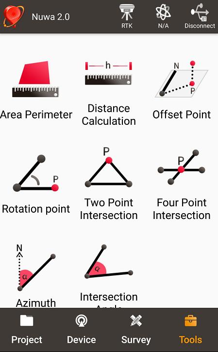
57 4. Introduction of Nuwa Nuwa is the Tersus survey app, which is running in the Android phone. All the configure commands for the David are input with Nuwa, and all the operation of David are done with Nuwa. Four tabs menus are provided in the main window. They are Project, Device, Survey and Tools. See the Nuwa user manual for detail. Figure 50 Booting up page! Tersus Survey Nuwa is supporting Android system; no IOS version is available now. The minimal requirements for Android phone: 1) The phone must support OTG, otherwise, it can t be connected to David with cables, but only with Bluetooth. 2) The Android system is 6.0 or later version.! 1) There are lots of Android versions in market, so an Android phone meeting the minimal requirements above may still have problems to run Nuwa. 2) Nuwa is tested with: Huawei Mate 7/Honor 7/9, Oppo A57, Vivo X9 and Samsung C7 Pro. 3) It s highly recommended that an Android phone with better hardware performance than those above is used to run Nuwa. 56 / 83


58 Figure 51 Four Main Windows of Nuwa 57 / 83
59 APPENDIX A 5. Specification 5.1 David Receiver Table 23 David GNSS Performance GNSS Performance Single positioning 1.5m RMS (Horizontal) 3.0m RMC (Vertical) Position Accuracy RTK Positioning 10mm+1ppm (Horizontal) 15mm+1ppm (Vertical) Static post processing 3mm+0.5ppm (Horizontal) 5mm+0.5ppm (Vertical) Time to First Fix Cold Start: <50s Warm Start: <30s Reacquisition 0.5 s L1 (typical) 1.0 s L2 (typical) Data Rate Measurements 20Hz Position 5Hz Time Accuracy 20ns RMS Velocity Accuracy 0.03m/s RMS C/A Code 10cm Measurement Precision P Code(zenith direction) 10cm Carrier Phase(zenith 1mm direction) Physical Description Size 104*65*31 mm 3 (David only) Weight 250g (David only) Mechanical Drawing 58 / 83
60 ENVIRONMENTAL Operating Temperature -40 C to +85 C Storage Temperature -55 C to +95 C Humidity MIL-STD-810G, Method Procedure II (95%) Random Vibration MIL-STD 810G Method 514.6, Category 24 (7.7 g RMS) Sinusoidal Vibration IEC (5 g) Bump ISO (25 g) Shock Operating: MIL-STD-810G, Method 516.6, Procedure I (40 g) Non-operating: MIL-STD-810G, Method 516.6, Procedure V (75 g) Water & dust proof IP67 Power Requirement Input Voltage VDC Power Consumption 3.2W without external Radio 6.2W with external 1W radio RS900C 9.8W with external 2W radio RS400L2 Figure 52 Panel of David 59 / 83
61 Table 24 Pin Definition Connector Pin COMM1 COMM2 DC No. LVTTL RS PWR PWR PWR 2 GND GND GND 3 TXD1 TXD2 4 RXD1 RXD2 5 GND GND 6 CAN_H/PPS 1 USB D+ 7 CAN_L/EVENT 1 USB D- Note 1: The default configure for pin6 and pin7 in COMM1 port are CAN_H and CAN_L. The two signals are multiplexed with PPS and EVENT. This feature is related to FW release, contact support@tersus-gnss.com for confirmation. Figure 53 Pin Definition of the COMM1/COMM2/DC ports 60 / 83
62 5.2 ANTENNA AX3702 Table 25 Antenna AX3702 Antenna Specification Tracking signals GPS L1/L2/L5; BDS B1/B2/B3; GLONASS L1/L2 Impedance 50 Ohm Polarization RHCP Axial Ratio 3dB Azimuth Coverage 360 Output VSWR 2.0 Peak Gain 5.5dBi Phase Center Error ± 2mm LNA Specification LNA Gain 40±2dB Noise Figure 2.0dB VSWR 2.0 Input Voltage 3.3~12V DC Operating Current 45mA Ripple ± 2dB Physical Description Dimension Φ152*62.2mm Signal Connector TNC Female Installation connector 5/8 x 11 Environment Operating temperature -45 C C Storage temperature -45 C C Damp 45% - 95% Mechanical Drawing 61 / 83
63 5.3 1W Radio RS900C Table 26 Specification for RS900C General Specification Working Frequency 915MHz Data level RS-232 Serial port baud rate Data interface DB-9 male Size 78 * 51.5 * 26.4 mm 3 Operating Temperature Antenna impedance 50 Input voltage DC 5V 12V Power consumption 3.0W (transmitting) 180mW (receiving) Receiver Specification Sensitivity -123dBm (20kbps) Spurious response immunity 65dB Intermodulation immunity 60dB Stand by current 65mA saturation 90dB Distortion 5% Error rate 0.001% Transmission specification Modulation QPSK/BPSK Transmission power >1000mW Modulation distortion 3% Maximum frequency deviation 5KHz Transmission current 1000mA/DC 5V Carrier frequency tolerance 5*10-6 Spurious frequency components -65dB Sleep current 5uA Working range >2km (@1Mbps) >5Km (@20Kbps) Mechanical Drawing s 62 / 83
64 63 / 83
65 5.4 2W Radio RS400L2 Table 27 Specification for RS400L2 Communication Interface Interface 9.6kbps in the air Lemo connector, RS-232, baud rate Voltage and Power Input voltage DC 5 12V Power consumption in 6.5W (DC 12V, transmitting power 2W) 4W(DC 12V, transmitting power 1W) transmitting Power consumption in <400mW (DC 5V) receiving External Antenna Impedance 50 Ohm VSMR 1.5 Interface MCX female Modulation & Demodulation Modulation GMSK Data rate in air 9600bps@25KHz RF sensitivity Better than 13dB@-119dBm Code sensitivity -116 dbm BER 10E-5@9600bps Protocol Transparent EOT, TT450S and Tersus RF Specification Frequency range 10MHz (457MHz 467MHz) Channel width 25KHz Frequency ±1.5 ppm(25c) stability Channel number 10 configurable channels Adjacent channel selectivity 60dB High power dBm@DC5.5V (2W) Transmission power Low power (1W) dBm@DC5.5V Environment -30 C C (operating) Temperature -40 C C (storage) Mechanical Size 107 * 62 * / 83
66 65 / 83
67 5.5 30W Radio RS400L30 Table 28 RS400L30 Radio Specification Communication Interface DTE-DCE Interface 9.6kbps in the air Serial port: RS-232, Band rate Interaction High (about 30W) PWR LED: OFF 2 nd high (about 20W) PWR LED: BLUE Power level Middle (about 10W) PWR LED: RED Low (about 5W) PWR LED: RED&BLUE blink Charging Alarm DC V B4 DC V Battery Monitor B3 DC V B2 DC V B1 DC V Power In/Out Input voltage DC V Power in transmitting (typical) Transmitting prohibition voltage Power in receiving (typical) Input Impedance 85W (DC 12.8V, 30W output) 65W (DC 12.8V, 20W output) 46W (DC 12.8V, 10W output) 33W (DC 12.8V, 5W output) DC V (default) DC V (configure range) <3W (Input voltage DC 12.8V) 50 Ohm VSWR 1.5 Interface Modulation Data rate in air RF sensitivity Decode sensitivity Protocol Frequency range Channel width Stability Antenna TNC female Modulation/Demodulation GMSK 9600bps@25KHz Better than 13dB@-119dBm -116 dbm BER 10E-5@9600bps Transparent EOT, SOUTH Radio MHz 25KHz 1.5ppm (25C) 66 / 83

")
68 Channel number Adjacent channel selectivity 116 (channel are configurable, channel are fixed) 60dB Environment Temperature Operating C Dust proof and waterproof Size Weight Data port Power input port Installation Storage IP68 Physical Description C 165 * 74 * mm 3 with plastic protector About 1.75Kg LEMO EGA.0B.305 LEMO EGG.1B.302 Hook Mechanical Drawing Data Port Signal definition Pin 1: GND Pin 2: GND Pin 3: Output power (3A, same voltage as the input) Pin 4: RXD Pin 5: TXD 67 / 83

69 Pin 1: GND Pin2: PWR input Power input port 68 / 83
70 APPENDIX B 6. Typical operating The LEMO connectors in the David system support mis-installation avoidance. But it s highly recommended to double check the module/cable before they are installed to the correct ports. Mis-installation with force can damage the David.! The following may be used for David system: A battery bank for David An Android phone An external large capacity power if a base kit with 30W or with 2W radio station is used. A tripod (optional). A tribrach (optional) It s highly recommended that a David base variant is installed on a tripod. 6.1 David as a Rover to receive corrections from Internet! From section 6.1 to section 6.4, David and Android phone are connected with cables; refer to section for the connection with Bluetooth. 69 / 83
71 Figure 54 Outline of Android phone to David with Wire! Two cables are used to connect the COMM2 port of David to the USB port of the Android phone. They are: COMM2-7pin-USB & DB9 Male cable or COMM2-7pin-USB & 5pin cable. USB Type A Female to USB (Micro + Type C) OTG cable Table 29 Detailed steps for rover receive corrections from Internet Hardware Installation 1. Install the GNSS antenna on a ranging pole at a point interested. 2. Connect the antenna to David with the RF cable. 3. Connect the David s COMM2 port to the USB port of the Android phone with cables. 4. Power on the David with a battery bank. Software Configure 5. Run Nuwa, Device ->Device Connect 70 / 83


72 6. Connect Type USB 7. Press Connect Config to update accordingly. 8. Press Connect to enable the communication with the David. 9. Go back to: Device -> Rover Station 71 / 83

73 10. Select PDA Network+Default Server1, then press Detail to configure the parameters about the Network. 11. Select Network for Data Link 12. If Ntrip is selected for Protocol type, please input: IP, Port, Username, Password and Mount Point. 13. If TCP is selected for Protocol type, please input: IP and Port. 14. Go back to the Rover Station page and press Start. 15. If all the configure above are correct, the right page will show the rover is receiving RTK corrections. 6.2 David as a Base to transmit corrections to Internet Figure 55 Outline of Android phone to David with Wire! Two cables are used to connect the COMM2 port of David to the USB port of the Android phone. They are: 72 / 83
74 COMM2-7pin-USB & DB9 Male cable or COMM2-7pin-USB & 5pin cable. USB Type A Female to USB (Micro + Type C) OTG cable! It s highly recommended that a base David is installed on a tripod. Table 30 Detailed steps for Base transmit corrections to Internet Hardware Installation 1. Install the tripod at a point interested. 2. Install a tribrach on the tripod, adjust it to horizontal level and install the GNSS antenna and the antenna connector on it. 3. Connect the antenna to David with the RF cable. 4. Connect the David s COMM2 port to the USB port of the Android phone with cables. 5. Power on the David with a battery bank. Software Configure 6. Run Nuwa, Device ->Device Connect 7. Connect Type USB 8. Press Connect Config to update accordingly. 9. Press Connect to enable the communication with the David. 10. Go back to: Device -> Base Station 73 / 83


75 11. Select Auto Startup+PDA Network+Default Server1+Auto, then press Detail to configure the parameters about the Networ 12. If Auto Start is selected for Start Way, go to Step If Manual Start is selected for Start Way, input the base s position manually. 14. If Ntrip protocol is selected, please input: IP, Port, Username, Password and Mount Point. 15. Go back to the Base Station page and press Start 16. If all the configure above are correct, the right page will show the base is transmitting RTK corrections. 6.3 Radios Transmit RTK Corrections between Two Davids 74 / 83
76 ! 1W base must work with 1W rover. 2W base must be work with 2W rover. 30W base must work with 2W rover. Only 30W base and 2W rover are given in this section since the other two configure are very simple. BASE Rover Figure 56 Outline of Base/Rover with Radios Table 31 Detailed steps for David with Radios Hardware Installation for the 30W Base 1. Install the two tripods at the points interested. 2. Install the 30W radio antenna with the telescopic pole for radio antenna. 3. Refer to Figure 42, install the metal plate, the GNSS antenna connector and the 30W radio antenna on one tripod. 4. Install a tribrach on the other tripod, adjust it to horizontal level and install the GNSS antenna and the antenna connector on it. 5. Connect the antenna to the base David with the RF cable. 6. Connect the David s COMM2 port to the USB port of the Android phone with cables. 7. Install the RF cable from the telescopic pole to the 30W radio station. 8. Connect the COMM cable to 30W radio, and to the base Daivd s DC port, respectively. Then connect it to the power cable for 30W radio. 9. Double check the cables above and connect the power cable to the external battery. Hardware Installation for the 2W Rover 10. Install the GNSS antenna on a ranging pole and place it at the point interested. 11. Connect the rover antenna to the rover David with the RF cable. 12. Install the COMM2-7pin-USB & 5pin cable to the COMM2 port of the rover David, and connect the other two connectors to the USB port of the Android phone with cables and to the 2W radio station, respectively. 75 / 83


77 13. Power on the David with an external battery bank. Software Configure for the 30W Base 14. Refer to to communicate the Android phone with the base David. 15. In Survey Nuwa, go to: Device -> Base Station 16. Select Auto +Ex.Radio RTCM 32, press Detail 17. If Auto Start is selected for Start Way, go to Step If Manual Start is selected in for Start Way, input the base s position manually. 19. Press OK to go back to the Base page, press Start. Software Configure for the 2W Rover 20. Refer to to communicate the Android phone with the rover David. 21. Go back to: Device -> Rover Station 76 / 83
 If the collection frequency increased, the")
78 22. Select Ext.Radio+38400, press Detail 23. Data Link is Radio and ensure the Band Rate is correct. 24. Go back to the rover page, and press Start. 6.4 Data Collection for Post Processing! The size of the logging: Collect raw measurements at 1Hz (about 110KByte/min if 20 satellites are tracked, about 165KByte/min if 30 satellites are tracked) If the collection frequency increased, the data size will be increased proportionately. 77 / 83
79 David provides up to 4GB internal emmc card for data collection, before data collection, estimate whether the free space is enough for the data collection. Refer to Table 21 to delete the files on emmc card to get more free space. During data collection, the antenna must be installed on a tripod.! Rules for the file name & update time in the internal emmc card: 1) Name: file name is the xx..xx.dat, totally 8 digits, in which xxxx is the working time (seconds/100) of the David. For example, the David has worked 500 hours 40min, (500* *60)/100 = 18024, the file name will be dat. 2) Update time: if the David hasn t gotten the GNSS time, the update time of the files will be :0 (YYYYMMDD HH:MM). If the David has gotten the GNSS time, the update time will be the UTC time. Figure 57 Outline of Static Data Collection Table 32 Detailed Steps for Static Data Collection Hardware Installation 1. Install a tripod at a point interested. 2. Install a tribrach on the tripod, adjust it to horizontal level and install the GNSS antenna and the antenna connector on it. 3. Connect the antenna to the David with the RF cable. 78 / 83


80 4. Create communication between the David and the Android phone with cables, refer to section Software Configure 5. In Tersus Survey Nuwa, go to Survey->Static Survey 6. Ensure the necessary parameters, including data frequency and cutoff angle, etc. Press Start. 7. Follow steps 1-6 above to collect static data at other points interested. 6.5 Auto Base Station List Function If a base is setup with command POSAVE, according to its origianl definition, even if the receiver is installed at the same point. Aftera a power cycle, the fixed position may be different, see more about coommand POSAVE in the Log & Command document. For the users who what the base to keep the same fixed position after a power cycle, auto base station list function is 79 / 83
 Go to Menu Tool -> Base Network for Posave, the follwing page will be displayed. 3) Fill the valid position range, PosAve On and fill the time (unit is hour), press the Modify button.")
81 introduced. The procedure is introduced below: 1) Follow Figure 48 and the detailed steps in Table 19 to create communication between a David receiver and Tersus GNSS Center. 2) Go to Menu Tool -> Base Network for Posave, the follwing page will be displayed. 3) Fill the valid position range, PosAve On and fill the time (unit is hour), press the Modify button. It s recommended that valid position range is >20m. 4) After the time (in the example, 0.01 hour, that is, 36 seconds), the base will be fixed with the 36 seconds averaging position. 5) Press Refresh button, the fixed position will be displayed on the window. 80 / 83

82 6) Then after a power cycle, if the base is not moved 20m away from the last position, it will fixed with the same position, in the example, latitude will keep , longitude will keep and ellipsoid height will keep / 83
User Manual For David GNSS Receiver
 User Manual Version V1.0-20180428 User Manual For David GNSS Receiver 2018 Tersus GNSS Inc. All rights reserved. Sales & Technical Support: sales@tersus-gnss.com & support@tersus-gnss.com More details,
Sales & Technical Support: &
 Sales & Technical Support: sales@tersus-gnss.com & support@tersus-gnss.com Table of Content Table of Content...1 List of Figures...3 List of Tables... 4 Revision History... 5 1. Introduction...6 1.1 Overview...6
User Manual. User Manual For BX Series GNSS Receiver
 User Manual Version V2.1-20190419 User Manual User Manual For BX Series GNSS Receiver 2019 Tersus GNSS Inc. All rights reserved. Sales & Technical Support: sales@tersus-gnss.com & support@tersus-gnss.com
David GNSS Receiver Base & Rover Kits
 A ffordable Centimeter Precision for Everyone Base & Rover Kits METER Tersus The Tersus is a cost-efficient, palm-sized GNSS receiver designed for UAVs, AGVs, and surveying applica ons. Using an external
User Manual For BX Series GNSS Receiver
 User Manual Version V1.0-20180629 User Manual User Manual For BX Series GNSS Receiver 2018 Tersus GNSS Inc. All rights reserved. www.tersus-gnss.com Aug, 2016 Revision Description Date Owner 1 Issued for
----STAR S86 GPS Receiver. User Guide. SOUTH CO., Ltd.
 ----STAR S86 GPS Receiver User Guide SOUTH CO., Ltd. www.southsurveying.com Sales@SOUTHsurveying.com 2 CONTENTS Chapter 1 Introduction... 1 STAR S86 GPS - System Summary... 1 Technical Specification...
GNSS Antenna. David GNSS Receiver. WiFi. 12V DC Ntrip Modem. Ethernet SIM 2/3/4G. Tersus GeoBee. Cost-effective Solution for Ntrip Corrections
 GNSS Antenna SIM 2/3/ Cost-effective Solution for Corrections Cost-effective Solution for Corrections The is a dedicated and cost-effec ve solu on to transmit or receive corre ons. With Tersus Caster Service,
Quick Start. Precis-BX305. Precise GNSS RTK Board.
 Quick Start Precis-BX305 Precise GNSS RTK Board www.tersus-gnss.com December, 2016 Quick Start Guide of Precis-BX305 This quick start guide provides the basic information needed to set up and use Precis-BX305
User Manual. User Manual. Precis-BX316R. User Manual Tersus GNSS Inc. All rights reserved.
 User Manual Version V1.0-20170623 User Manual User Manual Precis-BX316R 2017 Tersus GNSS Inc. All rights reserved. Sales & Technical Support: sales@tersus-gnss.com & support@tersus-gnss.com More details,
For BX316/BX316R/BX316D Receivers
 User Manual Version V1.0-20171106 User Manual User Manual For BX316/BX316R/BX316D Receivers 2017 Tersus GNSS Inc. All rights reserved. Sales & Technical Support: sales@tersus-gnss.com & support@tersus-gnss.com
Contents. Chapter 1 Brief Introduction of K9 series Chapter 2 K9 series mainframe The appearance of mainframe Interface...
 Contents Chapter 1 Brief Introduction of K9 series... 1 Chapter 2 K9 series mainframe... 2 2.1 The appearance of mainframe... 2 2.2 Interface... 2 2.3 The installation of battery... 3 2.4 Guiding light
G10 G10 G10 LAND SURVEYING RTK GNSS SYSTEM RTK GNSS SYSTEM RTK GNSS SYSTEM. GENEQ inc. GNSS RTK measurement technology revolution
 GENEQ inc. S C I E N T I F I C I N S T R U M E N T S LAND SURVEYING RTK GNSS SYSTEM RTK GNSS SYSTEM RTK GNSS SYSTEM G10 G10 G10 The new generation full function GNSS Receiver GNSS RTK measurement technology
User Manual BX306. User Manual Tersus GNSS Inc. All rights reserved.
 User Manual User Manual BX306 2017 Tersus GNSS Inc. All rights reserved. Sales & Technical Support: sales@tersus-gnss.com & support@tersus-gnss.com More details, please visit www.tersus-gnss.com www.tersus-gnss.com
CHC i80 GNSS Receiver QuickTour with LandStar7. (PDA Network Mode)
") CHC i80 GNSS Receiver QuickTour with LandStar7 (PDA Network Mode) 1.Prerequisites Hardware: CHC i80 rover, Controller Kit, SIM card,lithium Battery, pole Software: LandStar7 2.Steps to set i80 working
CHC i80 GNSS Receiver QuickTour with LandStar7 (PDA Network Mode) 1.Prerequisites Hardware: CHC i80 rover, Controller Kit, SIM card,lithium Battery, pole Software: LandStar7 2.Steps to set i80 working
SL800 GNSS RTK System User Manual
 SL800 GNSS RTK System User Manual User Manual Revision SatLab SL800 GNSS Receiver Revision Date Revision Number Description 1 st Nov 2017 1 SL800 User Manual (Release V1.0) 1 Table of Contents Introduction...
GPS Time and Frequency Reference Receiver
 $ GPS Time and Frequency Reference Receiver Symmetricom s 58540A GPS time and frequency reference receiver features: Eight-channel, parallel tracking GPS engine C/A Code, L1 Carrier GPS T-RAIM satellite
SLX-1 Multi-Application GNSS Receiver
 SLX-1 Multi-Application GNSS Receiver w w w.sa tla b g p s. c o m SLX-1 Multi-Application GNSS Receiver Designed for CORS Ready for Anything European Standards GPS GLONASS BEIDOU GALILEO SBAS QZSS Long
ALPHA RTK RECEIVER USER GUIDE
 ALPHA RECEIVER USER GUIDE Version 0.8 October 25, 2018 info@polaris-gnss.com https://www.polaris-gnss.com 1 Table of Contents 1. Overview... 3 1-1 Introduction... 3 1-2 Operation Guidelines... 3 1-3 Alpha
GLOBALSAT GPS Engine Board
 GLOBALSAT GPS Engine Board Hardware Datasheet Product No : MT-332(SMA) Version 1.0 GlobalSat WorldCom Corporation 16F., No. 186, Jian-Yi Road, Chung-Ho City, Taipei Hsien 235, Taiwan Tel: 886-2-8226-3799
Guide to GNSS Base stations
 Guide to GNSS Base stations Outline Introduction Example of a base station (TUMSAT) Preparation for setting up a base station Procedure for setting up a base station Examples at two other universities
GNSS POSITIONING SYSTEM USER MANUAL
 GNSS POSITIONING SYSTEM USER MANUAL 1 1. A BRIEF INTRODCTION RUIDE dedicates to offer the most advanced GNSS equipment to surveyors. RTK surveying technology, as a cutting-edged and efficient surveying
For BX316/BX316R Receivers
 User Manual Version V1.0-20171106 User Manual User Manual For BX316/BX316R Receivers 2017 Tersus GNSS Inc. All rights reserved. Sales & Technical Support: sales@tersus-gnss.com & support@tersus-gnss.com
User Manual. For AG960-Base. User Manual Tersus GNSS Inc. All rights reserved.
 User Manual Version V1.0-20170823 User Manual For AG960-Base 2017 Tersus GNSS Inc. All rights reserved. Sales & Technical Support: sales@tersus-gnss.com & support@tersus-gnss.com More details, please visit
For Nuwa App. User Manual. User Manual Tersus GNSS Inc. All rights reserved.
 User Manual Version V1.1-20181228 User Manual User Manual For Nuwa App 2018 Tersus GNSS Inc. All rights reserved. Sales & Technical Support: sales@tersus-gnss.com & support@tersus-gnss.com More details,
GETTING STARTED GUIDE X91GNSS
 GETTING STARTED GUIDE X91GNSS Copyright Copyright 2009-2011 CHC. 2010-Shanghai HuaCe Navigation Technology Ltd. All rights reserved. The CHC are trademark of Shanghai Huace Navigation Technology Limited.
Catalog
 - 1 - Catalog 1. Description...- 3-2. Features...- 3-3. Applications... - 3-4. Block Diagram...- 3-5. Electrical Characteristics... - 5-6. Operation... - 5 - Power on Reset... - 5 - Working mode... - 6
KRONOS C3 Receiver User Guide
 KRONOS C3 Receiver User Guide Copyright Copyright 2015-2016 HORIZON Survey Instruments Services Pte Ltd. All rights reserved. The KRONOS are trademark of Survey Instruments Services Pte Ltd. All other
Quick Start. Tersus GNSS Center. Configuration Tools for Tersus GNSS RTK Systems.
 Quick Start Tersus GNSS Center Configuration Tools for Tersus GNSS RTK Systems www.tersus-gnss.com July, 2016 1. Quick Start Guide of Tersus GNSS Center This quick start guide provides the basic information
SA-320 Installation Guide SA-320. Installation Guide. Date: Mar, 2011 Version: 2.5. All Rights Reserved
 SA-320 Installation Guide Date: Mar, 2011 Version: 2.5 All Rights Reserved Page 1 TABLE OF CONTENTS 1. Product Overview......3 1.1 Main Features...3 1.2 Applications.....3 1.3 Package Content.....3 2.
maxon document number:
 maxon document number: 791272-04 1 Table of contents... 2 2 Table of figures... 3 3 Introduction... 4 4 How to use this guide... 4 5 Safety Instructions... 5 6 Performance Data... 6 6.1 Motor data... 6
Safety Information. CHC M6 GNSS Receiver. Revision 1.0 October 2017
 Safety Information il CHC M6 GNSS Receiver Revision 1.0 October 2017 Copyright Copyright 2016-2017 CHC Shanghai Huace Navigation Technology Ltd. All rights reserved. The CHC are trademark of Shanghai Huace
USER MANUAL FIELDBEE AND RTK BEE STATION FULL VERSION. WE PROVIDE ONLINE SUPPORT: VERSION 1.0.
 USER MANUAL FULL VERSION VERSION 1.0. FIELDBEE AND RTK BEE STATION WE PROVIDE ONLINE SUPPORT: support@efarmer.mobi info@efarmer.mobi CONTENTS TABLE OF CONTENTS INTRODUCTION... 3 3 WAYS OF USING FIELDBEE...
GeoMax GNSS Zenith10 & Zenith20 Series
 GeoMax GNSS Zenith10 & Zenith20 Series GeoMax About Us At GeoMax we provide a com- group with strong market At GeoMax, we concentrate on prehensive portfolio of inte- positions within measurement providing
Catalog
 - 1 - Catalog 1. Overview... - 3-2. Feature...- 3-3. Application... - 3-4. Block Diagram... - 3-5. Electrical Characteristics...- 4-6. Operation...- 4-1) Power on Reset... - 4-2) Sleep mode...- 4-3) Working
The new geo-fennel. FGS 1 GNSS Receiver
 The new geo-fennel FGS 1 GNSS Receiver 1 FGS 1 Unique GPS Set for multipurpose applications The geo-fennel FGS 1 is a robust receiver designed for challenging environments integrated into a compact device
The new geo-fennel. FGS 1 GNSS Receiver
 The new geo-fennel FGS 1 GNSS Receiver 1 FGS 1 Unique GPS Set for multipurpose applications The geo-fennel FGS 1 is a robust receiver designed for challenging environments integrated into a compact device
Indian Institute of Technology Kanpur Department of Civil Engineering
 Indian Institute of Technology Kanpur Department of Civil Engineering Inquiry No- CE/JNM/2013-14/R-10 30 December, 2013 Subject: Quotation for supply of Integrated System/Smart System Reflectorless Robotic
E205 Long Range Wireless Modem V1.0 Data Sheet
 E205 Long Range Wireless Modem V1.0 Data Sheet The Long Range Wireless Modem E205 is a radio transmitter / receiver designed for transparent wireless data transmission over long distances. It operates
SA-320 Installation Guide SA-320. Installation Guide. Date: June, 2007 Version: 2.2. All Rights Reserved
 SA-320 Installation Guide Date: June, 2007 Version: 2.2 All Rights Reserved Page 1 TABLE OF CONTENTS 1. Product Overview......3 1.1 Main Features...3 1.2 Applications.....3 1.3 Package Content.....3 2.
IFR 4000 Portable Nav/Comm Test Set
 IFR 4000 Portable Nav/Comm Test Set Product Specification Note: A 15 minute warm-up period is required for all specifications. RF SIGNAL GENERATOR Marker Beacon Channel 72.0 to 78.0 MHz in 25 khz steps
Catalogue
 - 1 - Catalogue 1. Description... - 3-2. Features... - 3-3. Applications...- 3-4. Block Diagram... - 3-5. Electrical Characteristics...- 4-6. Operation...- 5 - Power on Reset... - 5 - Working mode... -
2W UHF MHz Radio Transceiver
 2W UHF410-470 MHz Radio Transceiver Specification Copyright Javad Navigation Systems, Inc. February, 2006 All contents in this document are copyrighted by JNS. All rights reserved. The information contained
RACELOGIC Antenna and Mount Options
 Antenna Options Your choice of antenna is critical to the accuracy of measurement. Racelogic provide a number of different antenna options, depending upon the measurement system, the type of vehicle being
Specifications. Trimble SPS985L GNSS Smart Antenna
 Receiver Name Configuration Option Base and Rover interchangeability Rover position update rate Rover maximum range from base radio Rover operation within a VRS network Heading and Moving Base operation
GLOBALSAT GPS Engine Board
 GLOBALSAT GPS Engine Board Hardware Data Sheet Product No : MT-5531 Version 0.1 Globalsat Technology Corporation 16F., No. 186, Jian-Yi Road, Chung-Ho City, Taipei Hsien 235, Taiwan Tel: 886-2-8226-3799
SV-MESH Mesh network series Catalogue
 Catalogue 1. Description... 3 2. Features... 3 3. Applications... 3 4. Block Diagram... 4 5. Electrical Characteristics... 5 6. Operation... 5 Power on Reset... 5 Working mode... 6 Router mode... 8 Setting
Version: 1.1 Revision: Data: Revised by: 006
 S9 III Version: 1.1 Revision: Data: 05-12-2012 Revised by: 006 2 Contents Chapter I : A brief introduction of S9 III... 5 Chapter II: S9 III mainframe... 7 II.1 The outlook of mainframe...7 II.2 Interfaces...7
CL4490 HARDWARE INTEGRATION GUIDE VERSION 1.0. FCC Notice.
 CL4490 HARDWARE INTEGRATION GUIDE VERSION 1.0 wireless.support@lairdtech.com FCC Notice WARNING: This device complies with Part 15 of the FCC Rules. Operation is subject to the following two conditions:
INSTALLATION AND OPERATING MANUAL
 INSTALLATION AND OPERATING MANUAL FOR RBDA-PCS-1/25W-90-A INDOOR REPEATER TABLE OF CONTENTS PARAGRAPH PAGE NO BDA OVERVIEW 3 BDA BLOCK DIAGRAM DESCRIPTION 3 FCC INFORMATION FOR USER 3 BDA BLOCK DIAGRAM
AgGPS RTK 450 MHz Mobile Base Station and Rover Unit: Setting Up
 6 August 2007 AgGPS RTK 450 MHz Mobile Base Station and Rover Unit: Setting Up This Support Note describes how to set up a Trimble AgGPS RTK 450 mobile base station and rover radio. Instructions apply
S O P H I S T I C A T E D A U T O M A T I O N
 S O P H I S T I C A T E D A U T O M A T I O N Introduction Cost-effective Radio modems to any serial communication application Low power models, different frequency ranges RS232 / / RS422 / 5V TTL interface
Videowave Wireless Video & Telemetry VTX1394SED & VRX1394SED
 Videowave Wireless Video & Telemetry VTX1394SED & VRX1394SED Enables wireless connection of PTZ and Dome type cameras Licence exempt operation (compliant with R&TTE directive) 15 selectable data channels
GLOBALSAT GPS+BDS Engine Board
 GLOBALSAT GPS+BDS Engine Board Hardware Data Sheet Product No : MT-5365B Version 1.0 GlobalSat WorldCom Corporation 16F., No. 186, Jian-Yi Road, Chung-Ho City, Taipei Hsien 235, Taiwan Tel: 886-2-8226-3799
GLOBALSAT GPS Engine Board
 GLOBALSAT GPS Engine Board Hardware Data Sheet Product No : MT-5110C Version 1.1 GlobalSat WorldCom Corporation 16F., No. 186, Jian-Yi Road, Chung-Ho City, Taipei Hsien 235, Taiwan Tel: 886-2-8226-3799
Catalog
 - 1 - Catalog 1. Overview...- 3-2. Feature... - 3-3. Application...- 3-4. Block Diagram...- 3-5. Electrical Characteristics... - 4-6. Operation... - 4-1) Power on Reset... - 4-2) Sleep mode... - 4-3) Working
Safety Information. Revision 1.1 November 2015
 Safety Information il CHC i80 GNSS Receiver Revision 1.1 November 2015 Copyright Copyright 2014-2015 CHC Shanghai HuaCe Navigation Technology Ltd. All rights reserved. The CHC are trademark of Shanghai
EB-230. Ultimate TRANSYSTEM INC. EB-230 Data Sheet
 GPS Engine Board EB-230 Data Sheet EB-230 EB-230 is an ultra miniature 12 x 12 mm 2 GPS engine board. It provides superior navigation performance under dynamic conditions in areas with limited sky view
Specifications. Trimble BX982 Modular GNSS Heading Receiver
 Name Configuration Option Base and Rover interchangeability Rover position update rate Rover maximum range from base radio Rover operation within a VRS network Heading and Moving Base operation Factory
RTKWARE UBR1 Technical Datasheet. ver1.1 (29/04/2015)
") RTKWARE UBR1 Technical Datasheet ver1.1 (29/04/2015) Table of Contents Table of Contents... 2 Overview... 3 Key-Features... 3 Applications... 3 Functional diagrams... 4 Power Distribution... 4 Data...
RTKWARE UBR1 Technical Datasheet ver1.1 (29/04/2015) Table of Contents Table of Contents... 2 Overview... 3 Key-Features... 3 Applications... 3 Functional diagrams... 4 Power Distribution... 4 Data...
PC Tune PC Tune Test Procedures for 5100 Series Portable Radios
 PC Tune PC Tune Test Procedures for 5100 Series Portable Radios Part Number 002-9998-6513014 August 2008 Copyright 2006, 2007, 2008 by EFJohnson Technologies The EFJohnson Technologies logo, PC Configure,
1 What s in the shipping package?
 SST 900B 900 MHz RS 232/RS 485 Wireless Modem Quick Start Guide 1 What s in the shipping package? SST-900B Wireless Modem CA-0910 Quick Start CD 3dBi 900M Hz Antenna Guide 2 External switch introduction
ENRICHING YOUR DIGITAL EXPERIENCE NEW MEMBER TO WORLD'S MOST COMPLETE DMR PORTFOLIO PD98X
 ENRICHING YOUR DIGITAL EXPERIENCE NEW MEMBER TO WORLD'S MOST COMPLETE DMR PORTFOLIO PD98X www.hytera.com PD98X Highlight Brand New Features 01 Micro SD Card 02 Single Frequency Repeater Mode Based on micro
Setting up i80 CHC receiver in RTK mode using TcpGPS
 Sumatra, 9 E-29190 Málaga (Spain) www.aplitop.com Phone: +34 952439771 Fax: +34 952431371 Technical Note (tcpgps_en_v41_002_setting_up_chc_i80_in_rtk_mode) Setting up i80 CHC receiver in RTK mode using
500S Smart Antenna Installation and Operation Manual. P/N Rev. A 09/17 E29808
 500S Smart Antenna Installation and Operation Manual P/N 016-0171-668 Rev. A 09/17 E29808 Copyright 2017 1 Disclaimer While every effort has been made to ensure the accuracy of this document, Raven Industries
Leica GRX1200+ Series High Performance GNSS Reference Receivers
 Leica GRX1200+ Series High Performance GNSS Reference Receivers Leica GRX1200+ Series For permanent reference stations The Leica GRX1200+ Series, part of Leica's future proof System 1200, is designed specifically
RF1212 RF1212 Ultra-low Power ISM Transceiver Module V2.0
 RF1212 Ultra-low Power ISM Transceiver Module V2.0 Application: Features: Home automation Security alarm Telemetry Automatic meter reading Contactless access Wireless data logger Remote motor control Wireless
Smart Design Technology Co., Ltd.
 Mars700Mini-TMC GNS TC5000 TMC Module Smart Design Technology Co., Ltd. 20F-8, No.107, Sec 1,Jhongshan Rd. Sinjhuang City, Taipei County 242, Taiwan Phone: +886-2-8522-7628 Fax: +886-2-8522-7784 Contact:
SPECIAL SPECIFICATION 6744 Spread Spectrum Radio
 2004 Specifications CSJ 0924-06-244 SPECIAL SPECIFICATION 6744 Spread Spectrum Radio 1. Description. Furnish and install spread spectrum radio system. 2. Materials. Supply complete manufacturer specifications
The on board surveyor
 The on board surveyor A PPK solution for drone-mapping Introduction DROBIT is a high precision positioning system created for drone-based photogrammetry. Its working principle is differential correction
Leica GRX1200 Series High Performance GNSS Reference Receivers
 Leica GRX1200 Series High Performance GNSS Reference Receivers Leica GRX1200 Series For permanent reference stations The Leica GRX1200 Series, part of Leica s new System 1200, is designed specifically
NS HP & NS HP BD User s Guide
 NS HP & NS HP BD User s Guide Rev. 0.8 September 30, 2017 1 Table of Contents 1. INTRODUCTION... 3 2. FEATURES OF NS HP... 5 3. APPLICATIONS... 5 4. PIN OUT DESCRIPTION... 6 5. CHECK OUT BASIC GPS FUNCTIONALITY...
N o r t h G r o u p L T D. User Manual GNSS RTK Receiver SmaRTK Series
 1 Copyright Copyright 2007-2013 North. 2007 North Group LTD. All rights reserved. North is trademark of North Group LTD. All other trademarks are the property of their respective owners, 2007. Trademarks
Specifications. Trimble SPS985L GNSS Smart Antenna
 Receiver Name Configuration Option Base and Rover interchangeability Rover position update rate Rover maximum range from base radio Rover operation within a VRS network Heading and Moving Base operation
Specifications. Trimble SPS985 GNSS Smart Antenna
 Receiver Name Configuration Option Base and Rover interchangeability Rover position update rate Rover maximum range from base radio Rover operation within a VRS network Heading and Moving Base operation
GPS SMART ANTENNA (GWG4287SX)
") GPS SMART ANTENNA (GWG4287SX) SiRFSTARIII /LPx Specifications are subject to change without notice KOREA ELECTRIC TERMINAL CO., LTD. All right reserved http://www.ket.com 1. Introduction 1.1 Over view
GPS SMART ANTENNA (GWG4287SX) SiRFSTARIII /LPx Specifications are subject to change without notice KOREA ELECTRIC TERMINAL CO., LTD. All right reserved http://www.ket.com 1. Introduction 1.1 Over view
User Guide for KOLIDA GNSS Receiver -----S680
 User Guide for KOLIDA GNSS Receiver -----S680 Catalog CHAPTER 1. GENERAL INTRODUCTION... 2 1.1 PROFILE... 2 1.2 SPECIFICATIONS... 3 1.3 STANDARD CONFIGURATION... 4 1.4 INTRODUCTION OF HIGH PRECISION GNSS
DRF7020D20 20dBm ISM RF Transceiver Module V1.31
 DRF7020D20 20dBm ISM RF Transceiver Module V1.31 Features GFSK transceiver Module 433Mhz ISM frequency band 19.2K bps data rate Multiple channels 20dBm Max. output power Baud rate configurable 256 bytes
KCS TraceME TM-203 / R9F4 GPS / GPRS / SMS / RFID module, OEM Version
 KCS TraceME TM-203 / R9F4 GPS / GPRS / SMS / RFID module, OEM Version The KCS GPRS/GPS range of modules enables you to remotely track & trace people, animals and a variety of objects, e.g. cars, trucks,
Localizer provides signal generation over the Localizer band of to MHz with 90 Hz and 150 Hz tones, amplitude modulated
 The IFR 4000 verifies the operation and installation of ILS, VOR and Marker Beacon receivers and VHF/UHF AM/FM and HF AM/SSB transceivers. The IFR 4000, with its lightweight size (under 8 lbs.), long run
SETTOPSURVEY, S.L. Bofarull 14, Barcelona (Spain) Phone: (+34) Fax: (+34)
 Phone: (+34) Fax: (+34)") USER MANUAL v.5 Settop Repeater 2 Index SETTOP Repeater... 3 Control Software... 5 SETTINGS: Configuration... 7 RADIO... 8 INTERNET SETUP: Configuration of the internet protocols... 10 CELLULAR MODEM:
USER MANUAL v.5 Settop Repeater 2 Index SETTOP Repeater... 3 Control Software... 5 SETTINGS: Configuration... 7 RADIO... 8 INTERNET SETUP: Configuration of the internet protocols... 10 CELLULAR MODEM:
A50/A51/A60. June 2008 (4th Edition) All Rights Reserved
 All Rights Reserved") A50/A51/A60 June 2008 (4th Edition) All Rights Reserved Part I - A50/A51 RS-232 to RS-422/RS-485 Converter A50/A51 RS-232 to RS-422/RS-485 Bidirectional Converter Part II - A60 RS-232 Surge Protection
A50/A51/A60 June 2008 (4th Edition) All Rights Reserved Part I - A50/A51 RS-232 to RS-422/RS-485 Converter A50/A51 RS-232 to RS-422/RS-485 Bidirectional Converter Part II - A60 RS-232 Surge Protection
Ku-Band VSAT Block Up Converters
 FEATURES Single box BUC output power levels to 10W RS485 M&C capability Accurate RF Power Monitoring Maintenance Free Operation +24VDC or +48 VDC input voltage OPTIONS 10W L-Band to Ku-Band Block Up Converter
TRIMMARK 3 Radio Modem
 TRIMMARK 3 Radio Modem User Guide F Version 1.25 Revision A Part Number 44104-10-ENG December 2004 Corporate Office Trimble Navigation Limited Geomatics and Engineering Division 5475 Kellenburger Road
G3P-R232. User Manual. Release. 2.06
 G3P-R232 User Manual Release. 2.06 1 INDEX 1. RELEASE HISTORY... 3 1.1. Release 1.01... 3 1.2. Release 2.01... 3 1.3. Release 2.02... 3 1.4. Release 2.03... 3 1.5. Release 2.04... 3 1.6. Release 2.05...
K Series GNSS Receiver Getting Started
 K Series GNSS Receiver Getting Started K Series GNSS Receiver Getting Started Hi-Target Surveying Instrument Co., Ltd All Rights Reserved K Series GNSS Receiver Getting Started Content 1. Introduction
A Tallysman Accutenna TW2710 / TW2712 Magnet Mount Multi-Constellation Antenna
 A Tallysman Accutenna TW2710 / TW2712 Magnet Mount Multi-Constellation Antenna The TW2710 / TW2712 employs Tallysman s unique Accutenna technology covering the BeiDou B1, Galileo E1, GPS L1, GLONASS L1
CL4790 HARDWARE INTEGRATION GUIDE VERSION 3.0. Americas: Europe: Hong Kong:
 CL4790 HARDWARE INTEGRATION GUIDE VERSION 3.0 Americas: +1-800-492-2320 FCC Notice WARNING: This device complies with Part 15 of the FCC Rules. Operation is subject to the following two conditions: (1)
Leica Spider Infrastructure HW Solutions Introducing: Leica GR30 & GR50
 Leica Spider Infrastructure HW Solutions Introducing: Leica GR30 & GR50 Reliable solutions for today and tomorrow Leica Spider Integrated Solutions Introducing: Leica GR30 & GR50 Outline Introducing Leica
PDL Base. Radio Modem User's Guide. Revision 0.2 (preliminary) May 1999 Copyright 1999 Pacific Crest Corporation Document M00522
 May 1999 Copyright 1999 Pacific Crest Corporation Document M00522") i PDL Base Radio Modem User's Guide Revision 0.2 (preliminary) May 1999 Copyright 1999 Pacific Crest Corporation Document M00522 Pacific Crest Corporation 990 Richard Avenue, Suite 110 Santa Clara, CA
i PDL Base Radio Modem User's Guide Revision 0.2 (preliminary) May 1999 Copyright 1999 Pacific Crest Corporation Document M00522 Pacific Crest Corporation 990 Richard Avenue, Suite 110 Santa Clara, CA
Trio Q Data Radios. Licensed UHF Ethernet and Serial Data QR450
 Trio Q Data Radios Licensed UHF Ethernet and Serial Data QR450 1 The Trio Q Data Radios are advanced high speed licensed digital data radios, which provide both Ethernet and serial communications for the
SurvCE: configuration of S9III/S8 for a UHF radio connection
 SurvCE: configuration of S9III/S8 for a UHF radio connection This tutorial will show the basic settings of a S9III/S8 as a base, transmitting with its internal radio or with a generic external radio, and
MN5020HS Smart GPS Antenna Module
 1 Description The Micro Modular Technologies MN5020HS Smart Global Positioning System (GPS) Antenna Module is a complete 20-channel receiver with an integrated 18 x 18 mm patch antenna. With this highly
Ct-G551. Connectec. SiRF V GPS Module. Specifications Sheet V0.1. Features: Ct-G551 V0.1 Specification Sheet
 SiRF V GPS Module Ct-G551 Specifications Sheet V0.1 Features: SiRF StarV ultra low power chipset GPS, GLONASS, Galileo and SBAS reception for high GNSS availability and accuracy Compact module size for
Embedded Radio Data Transceiver SV611
 Embedded Radio Data Transceiver SV611 Description SV611 is highly integrated, multi-ports radio data transceiver module. It adopts high performance Silicon Lab Si4432 RF chip. Si4432 has low reception
XLR PRO Radio Frequency (RF) Modem. Getting Started Guide
 Modem. Getting Started Guide") XLR PRO Radio Frequency (RF) Modem Getting Started Guide XLR PRO Radio Frequency (RF) Modem Getting Started Guide 90002203 Revision Date Description A September 2014 Initial release. B March 2014 Updated
XLR PRO Radio Frequency (RF) Modem Getting Started Guide XLR PRO Radio Frequency (RF) Modem Getting Started Guide 90002203 Revision Date Description A September 2014 Initial release. B March 2014 Updated
Guide to GNSS Base stations
 Guide to GNSS Base stations Outline Introduction Example of Base Station (TUMSAT) Preparation for setting up a base station Procedure for setting up a base station Example of each Univ. Based on documents
C-Band VSAT Block Up Converters
 FEATURES Single box BUC output power levels to 20W RS485 M&C capability Accurate RF Power Monitoring Maintenance Free Operation +24VDC or +48 VDC input voltage OPTIONS Antenna Mounting Kit Form A Summary
M8 Hardware Operating Instructions
 M8 Hardware Operating Instructions SMART MAX GEOSYSTEMS CO., LTD i Preface Thank you for choosing SMG s M8. The M8 is a high-accuracy and high-performance multi-frequency GNSS RTK and mapping system professionally
GAUSS High Power UHF Radio
 [] Table of contents Table of contents... 1 1. Introduction... 3 Features... 4 Block Diagram... 6 2. Pinouts... 7 3. Absolute Maximum Ratings... 9 4. General Recommended Operating Conditions... 10 5. RF
Leica GPS900 Equipment List
 Leica GPS900 Equipment List 2 GPS900 Package 1. GPS900 RTK Rover 1.1 GPS900 Controller The controller can be connected to the ATX900 with a Bluetooth connection or can be connected using a cable. 1.1.1