----STAR S86 GPS Receiver. User Guide. SOUTH CO., Ltd.
|
|
|
- Jennifer Horn
- 6 years ago
- Views:
Transcription
1 ----STAR S86 GPS Receiver User Guide SOUTH CO., Ltd.
2 2 CONTENTS Chapter 1 Introduction... 1 STAR S86 GPS - System Summary... 1 Technical Specification... 2 Standard Configuration List... 3 Chapter 2 The Hardware of STAR S Interface of receiver Charging Communication Cable Controller-PC Cable Keys and indicator lights Chapter 3 Accessories of STAR S Instrument Case (soft bag) Battery and charger for Controller Transmitting/Receiving antenna of Data link Cables Chapter 4 Operation Instruction of STAR S86 indicator light Initialization interface Setting mode Mode select menu System setting Collection mode Module setting Chapter 5 Data Manage and Transfer Register Receiver Upgrade... 49
3 Chapter 1 Introduction STAR S86 GPS - System Summary STAR S86 combines the advantages of SOUTH series RTK products, engaging advanced technology and the concept of continuous innovation, bringing the most advanced surveying solution to surveyors, offers higher accuracy and more reliability. STAR S86 includes built-in radio, and GSM/GPRS or CDMA modules used simultaneously or separately, allowing longer baselines within the mobile network. STAR S86 features the ARM framework with a 400MHz CPU kernel, accommodating multi-tasking, faster processing in real time. STAR S86 uses USB MASS STORAGE standard protocol, for faster speed and flexible operation. STAR S86 has the following features: (1) Integrated design, high quality screen, and convenient operation. (2) The core technology of data link has improved typical RTK baselines, STAR S86 features built-in transmitter radio eliminating the need for cable and heavy external battery. (3) The built-in batteries package insures 12 hours work time, housed in the receiver enclosure and charging by plug in power. (4) STAR S86 has built in radio, built in GSM/GPRS module or CDMA module to user requirements. (5) STAR S86 adopts the latest ARM 9 400MHz CPU, faster processing speed, more memory and faster real time processing. (6) The powerful OS features multi-tasking utilising the standard compact disk file system; STAR S86 is more reliable and stable. Convenient data management and maintenance. (7) File system using USB MASS STORAGE standard protocol, provides faster downloading speed. (8) All-alloy enclosure is shock-proof, dust-proof, water-proof design, latest radio shielding. 1
4 Technical Specification (1) Channels (extend 72 channels): 14L1+14L2 GPS 2 SBAS 12L1+12L2 GLONASS (optional) (2) Accuracy: Static horizontal accuracy: 3mm + 1ppm Static vertical accuracy: 5mm + 1ppm Static work range : < =100km RTK horizontal accuracy: 10mm + 1ppm RTK vertical accuracy: 20mm + 1ppm RTK work range (built-in radio) : <= 7km (external radio) <= 10km RTK Initialization time: typical 15 seconds (3) Communication: Standard USB protocol, USB2.0, serial port (RS-232), Bluetooth (4) Data link: 0.5W~2W, GPRS/CDMA (internal) and 25W (external) (5) Physical parameters: Dimension (L X W X H):154 x 154 x 78mm Weight: 1.35kg Operating temperature: -30 ~65 Storage temperature: -40 ~85 Housing: All-alloy enclosure Waterproof Dust-proof: IP65 (6) Electric parameters (A) Two built-in lithium batteries packages Operating time: 15 hours to 20 hours (full charged) Charging time: 9 hours (B) Power: <1.8W External power supply: 10V~15V DC Note: The specifications are available when 5 or more satellites are visible, following the recommended procedure in product manual. Severe multi-path effect, volatile ionosphere environment and HDOP value will influence the 2
5 performance severely. Standard Configuration List The standard configuration of STAR S86 (1+1) is as follow table, Items QTY. Type STAR S86 Base Station 1 unit Charger of Receiver 1 Carrying Case 1 Soft bag 1 Plummet and Tribrach & connector 1 All-direction Antenna 1 HI Measuring plate 1 Measuring Tape 1 STAR S86 Rover Station 1 unit Charger of Receiver 1 set Carrying Case 1 Soft bag 1 Plummet and Tribrach & connector 1 set All-direction Antenna 1 HI Measuring plate 1 Measuring Tape 1 Controller 1 Lithium Battery of Controller 2 Charger of Controller battery 1 set Receiver-controller Cable 1 SD card& Reader 1 set BLUETOOTH 1 Standard Configuration Standard Configuration Table-1 Standard Configuration List Note: Users also can select 15w/25w high power radio or 2w/5w radio with affiliated cable, transmitting antenna. 3

6 Chapter 2 STAR S86 Hardware 2.1 Interface of receiver STAR S86 receiver is as following figure 2-1, Figure 2-1 Screen of receiver STAR S86 receiver integrates the receiver, data collection, power supply, and radio module. With high quality LCD screen, all-alloy enclosure, and 3 proof designs, STAR S86 is built to withstand the harshest weather, roughest site conditions. 4
 (3)-----------Slot for connecting plummet and tribrach (4)-----------Slot for SIM Card (5)-----------External Radio port, 5 pins (6)-----------Communication port, 7 pins (7)-----------Charger &")
7 (4) (5) (6) (7) Figure 2-2 the port side of STAR S86 (1) Operation Button (refer to 3.1) (2) LCD Screen (refer to 3.2) (3) Slot for connecting plummet and tribrach (4) Slot for SIM Card (5) External Radio port, 5 pins (6) Communication port, 7 pins (7) Charger & External power supply port, 4 pins Note: COM2 is for external radio. COM1/USB is for data transfer. CH/BAT is for charging and external power supply. 5

8 2.2 Charging (1) STAR S86 battery package The batteries packages are embedded on the two sides of receiver. After charged full, the built-in radio can work continuously for more than 10 hours. Figure 2-3 dual batteries packages (2) Charging the STAR S86 The charger of STAR S86 - AC adapter cable and plug. Figure 2-4 Power plug 6

9 Figure 2-5 AC Adapter cable 1 240V AC plug 2, 3 Connect part 4 4 pin plug, when you charge, you need insert it to the charging port on the receiver. 5 Indicator light of charger. When the light CH1, CH2 turns red, indicating the battery is on charge. When the indicator turns green, the battery fully charged or the charger disconnected from the receiver. The receiver is not affected by the charging cycle; however it is recommended that the receiver is turned off. 7
10 2.3 Communication Cable Data communication cable is for downloading data, one connector has 7 pins, the other connector is the USB plug and serial RS232 plug, see as figure 2-6, Figure 2-6 Data communication cable Notice: when you insert the 7 pins plug to receiver, match the red point on plug with the red point the receiver. Serial RS232 plug is for external function requirements. 8


11 2.4 Controller-PC Cable Controller-PC cable is for communication between Psion controller and PC. It s composed of two sections, one is connected with controller, and the other is connected with USB port in PC. See as figure 2-7. Figure 2-7 Controller-PC cable 9
12 Items Function Function or status power key Power on/off, confirm, modify Power on/off receiver, confirm edit items, select modified items & Reset Key DATA light BT light RX light TX light Page up/down, return Force to power off Data indicator light Bluetooth light Receiving signal light Transmitting signal light Select modified items or return superior menu Power off in special condition, collected data hasn t any influence. It will blink as collecting interval time or transmitting interval time When Bluetooth connected, it will keep on Blinks as transmitting internal time Blinks as transmitting internal time 2.5 Keys and indicator lights TX light indicates status of transmitting signal, RX light indicates status of receiving signal. BT light is Bluetooth light; DATA light is the data transmitting/receiving light. The keys from left to light are Reset key, two Function keys and Power key. The indicator information as follows, 1. Static mode DATA light blinks as collecting data interval time. 2. Base mode (Radio) TX, DATA lights blink as transmitting interval time at the same time. 3. Rover mode (Radio) 10
13 RX light blinks at transmitting interval time. DATA light blinks at transmitting interval time after receiving differential signal. BT light indicates Bluetooth connection. 4. GPRS module work mode When GPRS connected, TX, RX lights blink alternately. DATA light will blinks as transmitting interval time after receiving differential signal. TX light remains on, indicating errors; the error type is defined by blinking sequence of RX light flash: Loss of GPRS connection or subscription error; wrong APN, user name or password rejected by CORS network. RX light blinks once: no base station or rover to connect, in VRS_NTRIP condition, it means error register code or waiting for verification, but the network is connected at this time. RX light blinks twice: disconnection from server RX light blinks 3 times: no antenna, bad signal, awaiting network signal. RX light blinks 4 times: TCP connection timeout or the IP address or port is incorrect. RX light blinks 5 times: unknown error. If the TX and RX keep on at the same time, it means module is closed. 5. Radio (1)Built-in radio (UHF) STAR S86 adopts 0.5w or 2w UHF built-in transmitting radio, which can reach 2~5km typical baseline. The built-in battery package provides adequate energy for the built-in radio continuously work for around 10 hours. (2) External radio To operate the STAR S86 and communication over long baselines upgrade to external radio switch from internal 2/5w or 15/15w external radio. Note: Always connect antenna to radio before use to avoid damage to the radio module. 11
14 (3) Module STAR S86 includes a built-in GPRS/CDMA module for connection to CORS networks extending baselines, improving accuracy and reliability. 12
 The instrument case of STAR S86 has two layers; the external is hard Yellow case, which is suitable for long distance transport or removable inner soft")
15 Chapter 3 STAR S86 Accessories 3.1 Instrument Case (soft bag) The instrument case of STAR S86 has two layers; the external is hard Yellow case, which is suitable for long distance transport or removable inner soft bag See as figure 3-1. Figure 3-1 Instrument case The hard case is small size, durable and shockproof, convenient for washing. See as figure

16 Figure 3-2 Hard case 14

17 3.2 Battery and charger for Controller About receiver battery and charger, please refer to chapter 2-2. About battery and charger for controller, see as figure 3-4, 3-5. Figure 3-4 Charger Figure 3-5 Controller battery 15
18 3.3 Transmitting/Receiving antenna of Data link STAR S86 uses a 450MHz omni-directional antenna, this operates as both transmitting antenna and receiving antenna. See as figure 3-6. Figure 3-6 Receiving & Transmitting Antenna If using the external radio, attach the 5.5db omni-direction antenna, the appearance is as figure
19 Figure


20 3.4 Cables 1. Communication cable Communication cable is for communication between the receiver and external radio, also has power supply function to allow receiver and external radio work for extended periods. See as figure 3-8 Figure Receiver-controller cable Receiver-controller cable is for communication between receiver and controller, see as figure
21 Figure 3-9 Receiver-controller cable 3. Multi-communication cable Multi-communication cable is used for communication between receiver and PC. Used for downloading static data and updating firmware. See as figure
22 Figure 3-10 Communication cable 20

23 4. Other accessories Bracket for controller Figure 3-11 Bracket 21
 connecting hole (2) measuring edge (3) the distance is L=120mm The HI measuring plate is placed")
24 Hi measuring plate It s used for measuring instrument height, see as figure Figure 3-12 Hi measuring plate (1) connecting hole (2) measuring edge (3) the distance is L=120mm The HI measuring plate is placed between receiver and connector. See as figure
25 Figure 3-13 Measure Height To measure the antenna height for a survey set up, measure the distance from the edge of measuring plate to a base point on the ground. SOUTH software will automatically compensate the measurement from the measure plate to the phase center of the antenna 23
 TX, DATA indicator light blinks at transmitting interval time at the same time. 3. Work in rover mode(radio) RX indicator light will blink at transmitting interval time.")

26 Chapter 4 Operation Instruction of STAR S86 indicator light 1. Work in Static mode DATA indicator light will blink at collection interval time. 2. Work in Base mode(radio) TX, DATA indicator light blinks at transmitting interval time at the same time. 3. Work in rover mode(radio) RX indicator light will blink at transmitting interval time. DATA indicator light will blink at transmitting interval time after receiving differential data. BT (Bluetooth) indicator light be illuminated when Bluetooth is connected. Initialization interface At power up of the STAR S86 receiver, the initialization interface will be displayed, Figure 4-1 Initialization interface There are two choices in this interface, setting mode and collection mode. To enter this interface click F2 to enter setting mode, otherwise, the countdown on the upper-left ends, it will enter collection mode 24


27 automatically. Setting mode The setting mode interface includes two main menus and a quit menu. The two main menus are that one is mode select menu and the other is system setting menu. select the menu that you need by pressing selection button(f1,f2), then press to confirm, see as figure 4-2. Figure 4-2 Setting interface Mode select menu After pressing the button mode select interface is displayed, see as figure 4-3, Figure
 Parameters setting in static mode Entering static mode interface, there are various parameters, such as mask angle, sample interval, record mode (there are two options, automatic and manual).")

28 There are three work modes to select, static mode, base mode and rover mode. Make a selection, Press button or to select, the last menu is for returning parent menu. (1) Parameters setting in static mode Entering static mode interface, there are various parameters, such as mask angle, sample interval, record mode (there are two options, automatic and manual). When you select automatic, the receiver will collect static data automatically after receiving enough satellites and good PDOP value. If you select manual, press button to start after receiving enough satellites and good PDOP, see as figure 4-4 Figure 4-4 There are three options on the bottom of the interface: OK, Edit and Exit. To modify parameters, move the cursor to the Edit, then press button to start modify parameters. On completion, press to return to OK, then press button to confirm it, to cancel the modified operation, select Exit 26


29 The detailed operations are as follows, Figure 4-5 Note: There are 3 special interval items, 0.1s, 0.2s and 0.5s, the GPS OEM main boards support. This option is available via a firmware upgrade. Figure
30 Note: When you using several STAR S86 receivers together set all parameters the same. (2) Parameters setting in base mode Enter base mode interface, set parameters for base mode, see as figure 4-7, Figure 4-7 There are 4 options in the interface, differential type, auto start, record. The function or options are as follow: Differential type:rtca,cmr,rtcm2.x (include RTCM2.0 and RTCM2.3) Interval: Transmitting interval, Default setting is 1 second. Auto start: Two options, Yes or No, if you select Yes, the base station will transmit automatically after receiving enough satellites and good PDOP value. If you select No, the base station transmits manually after judging the satellite situation. No is default setting. Record: In RTK mode, to record static data where GNSS or radio signal is poor, record static data and post-process to achieve high accuracy. No is default setting. See as figure4-8, 4-9, 28


31 Figure 4-8 Figure 4-9 Press to confirm to select the second setting interface, data-link settings. There are two options in this interface, data link, and channel. The 29

32 instructions are as follows: Data link: Four options, UHF, GPRS, external, dual transmit. To use internal radio, select UHF. To use the GPRS/GSM/CDMA module, select GPRS. For external radio, select external, for external radio and GPRS/GSM/CDMA module select dual transmit Channel: Channel means radio channel. There are 8 channels to choose from. On completion press to return to main interface, and move the cursor to OK and press to confirm your settings. The receiver returns to the initialization interface. See as figure 4-10~4-15 Figure


33 Figure 4-11 Figure
Parameter settings in Rover mode The rover mode parameters are the same as for base mode, set as for base mode. 4.3.2 System setting There are five options in system setting interface, display")
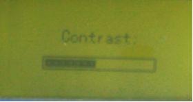
34 Figure 4-13 (3)Parameter settings in Rover mode The rover mode parameters are the same as for base mode, set as for base mode System setting There are five options in system setting interface, display setting, system info, self-check, file list, registration, the detailed operations and options are as follow: Display setting: there are three options, contrast, rotation and time zone. Adjust screen contrast in contrast setting. Rotation is for page turnover, it has two options, automatic and manual. There are several pages in collection interface, if you select automatic, these pages will display circularly, if you select manual, turn pages by pressing button. 32


35 Figure


36 Figure 4-17 On completion of parameters setting, press button to return parent menu.. System info: To check receiver serial number, firmware version, expired date and free space in memory. See as figure Figure 4-18 self-check: To test screen, LED and beeper, battery. See as Figure 4-19 Figure 4-19 File list: To check static data files in receiver memory. Check file size, start time, end time and so on. Pressing button when the cursor is on specific file 34


37 will pop up the confirm or delete options, where file detail is shown. see as figure 4-20, Figure 4-20 Registration: Input registration code, Registration code can be entered here if PC connection is unavailable. Only the last 16 Characters are needed. see as follow figure, 35

38 Figure 4-21 Collection mode (1) Static work interface On selection of static mode in settings, the receiver enters static mode after power on. If you select manual, press the F1 button twice to start recording data. If you select automatic, the receiver will record data automatically. There are three satellite information interfaces in this mode; set page turning by automatic or manual. See as figure


39 Figure 4-22 To end data recording data press F2 button, the system will prompt to end recording data. Press F2 button again, the system prompts for closing file, to cancel this operation, press F2 button. See as figure 4-23, 37


40 Figure 4-23 (2) Base work interface If base mode is selected in setting mode, the receiver will enter base mode after power on. See as figure 4-24 Figure 4-24 The word TRANSMIT will appear in the upper right corner of screen, press F1 button to enter base setup menu, see as figure 4-25, 38

41 Figure 4-25 There are three options in this menu, SINGLE TRANS, REPEAT TRANS and EXIT instructions are as follows, SINGLE TRANS: Using local coordinate as base coordinate to transmit, on completion, save this coordinate as a base coordinate file. This coordinate is used to revisit or continue the survey. REPEAT TRANS: To set the base station in the last position, use repeat transmit function, select the coordinate saved in receiver. See as the following figures, 39


42 The coordinate is calculated to the ground, input the antenna height before transmission, and see as below figure, Dev. Height. Measure from base point on the ground to the edge of Hi plate. EXIT: If you want to do nothing in this interface, you can select this item. After selecting options, press F1 button to confirm to enter the interface as figure 4-15, press F1 button again to begin, when five satellites are in view and PDOP value less than three, Start transmission! will appear and TX and DATA light will blink at the same time. To stop transmitting, press button to stop, the system will remind you to save the base coordinate, the coordinate can be saved and used for repeat surveys. 40


43 4). Rover work interface Selecting rover mode in setting mode, the receiver will enter rover mode at power on, see as figure 4-26, Figure 4-26 There are two pages in the collection mode. It includes satellites number, map, PDOP value, radio channel, module in use, battery power, longitude, latitude, ellipsoid height and so on. Module setting Press button to enter module setting interface in rover work mode, see as figure 4-27, 41


44 Figure 4-27 Note: In base mode, enter module setting interface when the base station is transmitting signal, and only change module parameters setting including module and channel. When the rover is connected to the base, to change radio channel or change from radio to GPRS/CDMA module, use the module setting interface, refer to data link and channel settings. Figure 4-28 To configure the radio, GPRS/CDMA module, enter config mode, connect the receiver with the PC program to make this configuration. See as follow figure 4-29, 42


45 Figure 4-29 Press button to enter configuration interface, then you can set parameters in PC program on connection, see as figure 4-30, 43

46 Figure 4-30 On completion, press any button to return to collection interface. 44
47 Chapter 5 Data Manage and Transfer 5.1 How to transmit data Firstly, you need to connect the receiver to PC by USB cable. The PC will identify the receiver as a Flash Disk. Power on the receiver and connect it with PC, you will see a removable disk icon at the right bottom of the computer screen, see as figure 5-1. Figure

48 Then you will find a Removable disk in My Computer, opening the folder will show the data in receiver memory. Figure 5-2 The record data file is *.sth, the editing time of file is the finishing time of recording data. Copy the static data from this directory directly. Notice: The name of record data is composed of 8 characters, the first four characters is point name, the middle three characters is date, for example, 31st, Jan is 031. The last one is session. 5.2 The use of configuration file When you open the file CONFIG,you will see it as follows: 46

49 Figure 5-3 Name Note 47
50 Point Name Session From 1 to 9 Ant Height Mask Angle Four characters, from 0 to 9, a, b, c z Unit is millimeter(mm) Contrast From 0 to 15 Language Serial Number From 0 degree to 45 degree Chinese language and English language It s composed of 27 digits and upper case characters. If you delete the file CONFIG,it will regenerate automatically after you restart the receiver. 5.3 Register and upgrade Register There are four methods for registration, 1. Modify configuration file, s60conf.ini (USB port). Please refer to figure 5-3. Replace the content of red frame, then save it. The registration code will be entered to the receiver. 2. Direct serial port command. Connect the receiver to your PC using serial port. Use any serial communication software (e.g. Super Terminal) to send the following command at the baud rate of 57600bps. REGI H NOTE: Your serial code should be different from the above one but with same formation. (COM port) See as following figure: 48

51 3. Using the controller. Use controller software ERTKPro. Refer to the ERTKPro User Manual for detail information. 4. Input the serial port from panel. Only the last 16 characters are required. See Registration in System configuration section. Please refer to about registration. Receiver Upgrade To upgrade receiver firmware obtain the program dnw.exe and upgrade file *.bin, the operation steps are as follow. Connect receiver to PC by COM port first, don t power on receiver 49

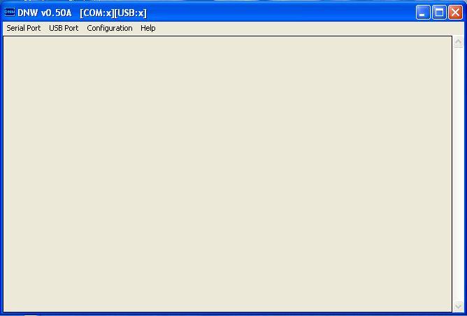
52 1. Firstly, run the software DNW, then click Configuration, from the window, select as the baud rate, and select the right Com Port. 50
53 51

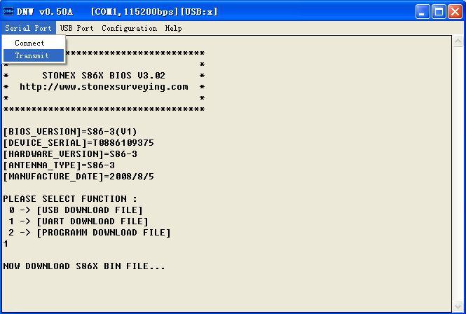
54 2. Click serial Port -> connect, if COM port is set correctly, on the top of the window, you will see the information of them. 52
55 3. Power up STAR S86 receiver
56 You will see please select function:, there are three options in below items, 0, 1, 2, please select 1 in 3 seconds. (this is very important!) 54
57 Tap transmit to import the firmware file, select the bin file. 55
58 56

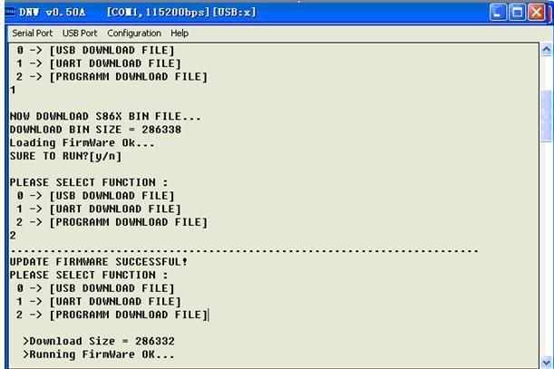
59 downloading will appear. 57

60 After downloading, press n, and then select 2 in 3 seconds! (This is also very important!!) 58
61 59

62 The messy code on screen indicates you are successful! Restart your receiver to run the upgraded version. 60
63 61
64 62
Contents. Chapter 1 Brief Introduction of K9 series Chapter 2 K9 series mainframe The appearance of mainframe Interface...
 Contents Chapter 1 Brief Introduction of K9 series... 1 Chapter 2 K9 series mainframe... 2 2.1 The appearance of mainframe... 2 2.2 Interface... 2 2.3 The installation of battery... 3 2.4 Guiding light
KRONOS C3 Receiver User Guide
 KRONOS C3 Receiver User Guide Copyright Copyright 2015-2016 HORIZON Survey Instruments Services Pte Ltd. All rights reserved. The KRONOS are trademark of Survey Instruments Services Pte Ltd. All other
GNSS POSITIONING SYSTEM USER MANUAL
 GNSS POSITIONING SYSTEM USER MANUAL 1 1. A BRIEF INTRODCTION RUIDE dedicates to offer the most advanced GNSS equipment to surveyors. RTK surveying technology, as a cutting-edged and efficient surveying
Safety Information. CHC M6 GNSS Receiver. Revision 1.0 October 2017
 Safety Information il CHC M6 GNSS Receiver Revision 1.0 October 2017 Copyright Copyright 2016-2017 CHC Shanghai Huace Navigation Technology Ltd. All rights reserved. The CHC are trademark of Shanghai Huace
Safety Information. Revision 1.1 November 2015
 Safety Information il CHC i80 GNSS Receiver Revision 1.1 November 2015 Copyright Copyright 2014-2015 CHC Shanghai HuaCe Navigation Technology Ltd. All rights reserved. The CHC are trademark of Shanghai
CHC i80 GNSS Receiver QuickTour with LandStar7. (PDA Network Mode)
") CHC i80 GNSS Receiver QuickTour with LandStar7 (PDA Network Mode) 1.Prerequisites Hardware: CHC i80 rover, Controller Kit, SIM card,lithium Battery, pole Software: LandStar7 2.Steps to set i80 working
CHC i80 GNSS Receiver QuickTour with LandStar7 (PDA Network Mode) 1.Prerequisites Hardware: CHC i80 rover, Controller Kit, SIM card,lithium Battery, pole Software: LandStar7 2.Steps to set i80 working
G10 G10 G10 LAND SURVEYING RTK GNSS SYSTEM RTK GNSS SYSTEM RTK GNSS SYSTEM. GENEQ inc. GNSS RTK measurement technology revolution
 GENEQ inc. S C I E N T I F I C I N S T R U M E N T S LAND SURVEYING RTK GNSS SYSTEM RTK GNSS SYSTEM RTK GNSS SYSTEM G10 G10 G10 The new generation full function GNSS Receiver GNSS RTK measurement technology
Setting up i80 CHC receiver in RTK mode using TcpGPS
 Sumatra, 9 E-29190 Málaga (Spain) www.aplitop.com Phone: +34 952439771 Fax: +34 952431371 Technical Note (tcpgps_en_v41_002_setting_up_chc_i80_in_rtk_mode) Setting up i80 CHC receiver in RTK mode using
SL800 GNSS RTK System User Manual
 SL800 GNSS RTK System User Manual User Manual Revision SatLab SL800 GNSS Receiver Revision Date Revision Number Description 1 st Nov 2017 1 SL800 User Manual (Release V1.0) 1 Table of Contents Introduction...
Version: 1.1 Revision: Data: Revised by: 006
 S9 III Version: 1.1 Revision: Data: 05-12-2012 Revised by: 006 2 Contents Chapter I : A brief introduction of S9 III... 5 Chapter II: S9 III mainframe... 7 II.1 The outlook of mainframe...7 II.2 Interfaces...7
K Series GNSS Receiver Getting Started
 K Series GNSS Receiver Getting Started K Series GNSS Receiver Getting Started Hi-Target Surveying Instrument Co., Ltd All Rights Reserved K Series GNSS Receiver Getting Started Content 1. Introduction
SETTOPSURVEY, S.L. Bofarull 14, Barcelona (Spain) Phone: (+34) Fax: (+34)
 Phone: (+34) Fax: (+34)") USER MANUAL v.5 Settop Repeater 2 Index SETTOP Repeater... 3 Control Software... 5 SETTINGS: Configuration... 7 RADIO... 8 INTERNET SETUP: Configuration of the internet protocols... 10 CELLULAR MODEM:
USER MANUAL v.5 Settop Repeater 2 Index SETTOP Repeater... 3 Control Software... 5 SETTINGS: Configuration... 7 RADIO... 8 INTERNET SETUP: Configuration of the internet protocols... 10 CELLULAR MODEM:
Z-Max Surveying System
 F630881-01_En RevB.09.30.03.qxd 10/9/03 5:58 PM Page 1 THALES NAVIGATION TM Z-Max Surveying System Pocket Guide www.thalesnavigation.com Printed in France. Part Number: 630881-01, Revision B No part of
GETTING STARTED GUIDE X91GNSS
 GETTING STARTED GUIDE X91GNSS Copyright Copyright 2009-2011 CHC. 2010-Shanghai HuaCe Navigation Technology Ltd. All rights reserved. The CHC are trademark of Shanghai Huace Navigation Technology Limited.
Four Simple Steps to Get Started
 Four Simple Steps to Get Started This guide provides an overview of the important features and instructions for how to set up and operate the Spectra Precision SP90m GNSS receiver. 1. Unpack and check
AgGPS RTK 450 MHz Mobile Base Station and Rover Unit: Setting Up
 6 August 2007 AgGPS RTK 450 MHz Mobile Base Station and Rover Unit: Setting Up This Support Note describes how to set up a Trimble AgGPS RTK 450 mobile base station and rover radio. Instructions apply
SurvCE: configuration of S9III/S8 for a UHF radio connection
 SurvCE: configuration of S9III/S8 for a UHF radio connection This tutorial will show the basic settings of a S9III/S8 as a base, transmitting with its internal radio or with a generic external radio, and
Manual Revision. Revision Date. H32 Series GNSS RTK System Manual V1.0
 Manual Revision Revision Date Times Directions 2012.0 1 V1.0 Preface Manual Usage Welcome to use H32 Series GNSS RTK system manual, This specification applies to H32 Series GNSS RTK system. Manual Introduction
Quick Start. Precis-BX305. Precise GNSS RTK Board.
 Quick Start Precis-BX305 Precise GNSS RTK Board www.tersus-gnss.com December, 2016 Quick Start Guide of Precis-BX305 This quick start guide provides the basic information needed to set up and use Precis-BX305
Indian Institute of Technology Kanpur Department of Civil Engineering
 Indian Institute of Technology Kanpur Department of Civil Engineering Inquiry No- CE/JNM/2013-14/R-10 30 December, 2013 Subject: Quotation for supply of Integrated System/Smart System Reflectorless Robotic
GeoMax GNSS Zenith10 & Zenith20 Series
 GeoMax GNSS Zenith10 & Zenith20 Series GeoMax About Us At GeoMax we provide a com- group with strong market At GeoMax, we concentrate on prehensive portfolio of inte- positions within measurement providing
TDS Survey Pro CE Version Setup RTK Base on known NAD83/WGS84 Point: Mapping Plane Geoid99 Modeling.
 TDS Survey Pro CE Version 2.1.8 Setup RTK Base on known NAD83/WGS84 Point: Mapping Plane Geoid99 Modeling. Pre-load known NAD83 State Plane Coordinates and appropriate NGS Geoid 99/96 data files into the
VBRC 5. Radio Communicator. Installer Manual
 VBRC 5 Radio Communicator Installer Manual 10 / 10 / 2013 CONTENT 1. INTRODUCTION...3 2. SYSTEM STRUCTURE...3 3. SYSTEM PROGRAMMING WITH PC SOFTWARE...5 4. TROUBLESHOOTING...6 5. FIRMWARE UPGRADE...7 6.
SLX-1 Multi-Application GNSS Receiver
 SLX-1 Multi-Application GNSS Receiver w w w.sa tla b g p s. c o m SLX-1 Multi-Application GNSS Receiver Designed for CORS Ready for Anything European Standards GPS GLONASS BEIDOU GALILEO SBAS QZSS Long
BRB900 GPS Telemetry System August 2013 Version 0.06
 BRB900 GPS Telemetry System August 2013 Version 0.06 As of January 2013, a new model of the BRB900 has been introduced. The key differences are listed below. 1. U-blox GPS Chipset: The Trimble Lassen IQ
TX CONTROLLER Model EM-IP Quick Start Guide
 TX CONTROLLER Model EM-IP Quick Start Guide 860 boul. de la Chaudière, suite 200 Québec (Qc), Canada, G1X 4B7 Tel.: +1 (418) 877-4249 Fax: +1 (418) 877-4054 E-Mail: gdd@gdd.ca Web site: www.gdd.ca Visit
User Guide for KOLIDA GNSS Receiver -----S680
 User Guide for KOLIDA GNSS Receiver -----S680 Catalog CHAPTER 1. GENERAL INTRODUCTION... 2 1.1 PROFILE... 2 1.2 SPECIFICATIONS... 3 1.3 STANDARD CONFIGURATION... 4 1.4 INTRODUCTION OF HIGH PRECISION GNSS
GNSS Conductor GF. User s Guide. (Document No. SE )
") GNSS Conductor GF User s Guide (Document No. ) www.furuno.com IMPORTANT NOTICE No part of this manual may be reproduced or transmitted in any form or by any means, electronic or mechanical, including photocopying
GNSS Conductor GF User s Guide (Document No. ) www.furuno.com IMPORTANT NOTICE No part of this manual may be reproduced or transmitted in any form or by any means, electronic or mechanical, including photocopying
The new geo-fennel. FGS 1 GNSS Receiver
 The new geo-fennel FGS 1 GNSS Receiver 1 FGS 1 Unique GPS Set for multipurpose applications The geo-fennel FGS 1 is a robust receiver designed for challenging environments integrated into a compact device
The new geo-fennel. FGS 1 GNSS Receiver
 The new geo-fennel FGS 1 GNSS Receiver 1 FGS 1 Unique GPS Set for multipurpose applications The geo-fennel FGS 1 is a robust receiver designed for challenging environments integrated into a compact device
For Nuwa App. User Manual. User Manual Tersus GNSS Inc. All rights reserved.
 User Manual Version V1.1-20181228 User Manual User Manual For Nuwa App 2018 Tersus GNSS Inc. All rights reserved. Sales & Technical Support: sales@tersus-gnss.com & support@tersus-gnss.com More details,
User Manual For David GNSS Receiver
 User Manual Version V1.0-20180702 User Manual For David GNSS Receiver 2018 Tersus GNSS Inc. All rights reserved. Sales & Technical Support: sales@tersus-gnss.com & support@tersus-gnss.com More details,
INSTRUCTION MANUAL IP REMOTE CONTROL SOFTWARE RS-BA1
 INSTRUCTION MANUAL IP REMOTE CONTROL SOFTWARE RS-BA FOREWORD Thank you for purchasing the RS-BA. The RS-BA is designed to remotely control an Icom radio through a network. This instruction manual contains
M8 Hardware Operating Instructions
 M8 Hardware Operating Instructions SMART MAX GEOSYSTEMS CO., LTD i Preface Thank you for choosing SMG s M8. The M8 is a high-accuracy and high-performance multi-frequency GNSS RTK and mapping system professionally
Topcon Receiver Utility: GNSS Receiver Firmware Update Process. Oscar R. Cantu
 Topcon Receiver Utility: GNSS Receiver Firmware Update Process Oscar R. Cantu TRU: GNSS Receiver Firmware Update Topcon Receiver Utility (TRU), product definition Office Processing and Reporting Software
Configuration of the Pacific Crest Radios using PDLCONF software PDL Base Radio
 Configuration of the Pacific Crest Radios using PDLCONF software PDL Base Radio This document will guide user s through configuration of the PDL Base Radio. Required items: PDL Base Radio, PDL Config software,
Sales & Technical Support: &
 Sales & Technical Support: sales@tersus-gnss.com & support@tersus-gnss.com Table of Content Table of Content...1 List of Figures...3 List of Tables... 4 Revision History... 5 1. Introduction...6 1.1 Overview...6
D-RTK. User Manual V
 D-RTK User Manual V1.0 2017.10 Searching for Keywords Search for keywords such as battery and install to find a topic. If you are using Adobe Acrobat Reader to read this document, press Ctrl+F on Windows
TDS Ranger Survey Pro CE Version RTK Base on known Control Point. RTK Rover - Localization with Control Points.
 TDS Ranger Survey Pro CE Version 2.1.8 RTK Base on known Control Point. RTK Rover - Localization with Control Points. Pre-load control Coordinates and appropriate NGS Geoid 99/96 data files into the Ranger
FieldGenius Technical Notes GPS Differential Corrections
 FieldGenius Technical tes GPS Differential Corrections Introduction The accuracy requirement of survey grade or mapping grade GPS applications for real time positioning requires the use of differential
USER MANUAL FIELDBEE AND RTK BEE STATION FULL VERSION. WE PROVIDE ONLINE SUPPORT: VERSION 1.0.
 USER MANUAL FULL VERSION VERSION 1.0. FIELDBEE AND RTK BEE STATION WE PROVIDE ONLINE SUPPORT: support@efarmer.mobi info@efarmer.mobi CONTENTS TABLE OF CONTENTS INTRODUCTION... 3 3 WAYS OF USING FIELDBEE...
LAB PROCEDURES: TOPCON TOOLS FAMILIARIZATION
 LAB PROCEDURES: TOPCON TOOLS FAMILIARIZATION This lab will cover the basic setup and processing options of Topcon Tools (TT). We will learn how to start a project, upload data and control files, set up
Leica Spider Infrastructure HW Solutions Introducing: Leica GR30 & GR50
 Leica Spider Infrastructure HW Solutions Introducing: Leica GR30 & GR50 Reliable solutions for today and tomorrow Leica Spider Integrated Solutions Introducing: Leica GR30 & GR50 Outline Introducing Leica
DragonLink Advanced Transmitter
 DragonLink Advanced Transmitter A quick introduction - to a new a world of possibilities October 29, 2015 Written by Dennis Frie Contents 1 Disclaimer and notes for early release 3 2 Introduction 4 3 The
VNet6 Plus User Guide
 VNet6 Plus User Guide Hi-Target Surveying Instrument Co., Ltd. All Rights Reserved Manual Revision File number: Revision Date Revision Level Description 2017-06-19 1 VNet6 Plus User Guide Preface Introduction
Index. Page (s) 1 4. Features
 1 4. Features") Instruction Manual Index Features Page (s) 1 4 LCD Monitor Load Design USB & USB Disk Drive Design Rotation/Scaling Thread Break Detect Work Sequence Frame protection Auto Origin Return Idle (Float) Mode
Instruction Manual Index Features Page (s) 1 4 LCD Monitor Load Design USB & USB Disk Drive Design Rotation/Scaling Thread Break Detect Work Sequence Frame protection Auto Origin Return Idle (Float) Mode
Galaxy G1. Galaxy G1 Measuring System. User Manual. *All Rights Reserved - 1 -
 Galaxy G1 Measuring System User Manual *All Rights Reserved - 1 - CONTENTS Chapter 1 Brief Introduction... - 4 - - 2-1.1 Introduction... - 4-1.2 Production functions... - 4-1.3 Features... - 5-1.4 Accessories
VBRC 4. Radio Communicator. Installer Manual
 VBRC 4 Radio Communicator Installer Manual 17 December 2014 CONTENT 1. INTRODUCTION...3 2. SYSTEM STRUCTURE...3 3. SYSTEM PROGRAMMING WITH PC SOFTWARE...5 4. TROUBLESHOOTING...6 5. FIRMWARE UPGRADE...7
User Manual. For AG960-Base. User Manual Tersus GNSS Inc. All rights reserved.
 User Manual Version V1.0-20170823 User Manual For AG960-Base 2017 Tersus GNSS Inc. All rights reserved. Sales & Technical Support: sales@tersus-gnss.com & support@tersus-gnss.com More details, please visit
V100 GNSS RTK System Getting Started
 V100 GNSS RTK System Getting Started V100 GNSS RTK System Getting Started Hi-Target Surveying Instrument Co., Ltd All Rights Reserved V100 GNSS RTK System Getting Started Content 1. Products Introductions
S320 and SurvCE RTK Base Unknown Location
 S320 and SurvCE RTK Base Unknown Location Part Number 874-0303-000 Released April 17, 2012 Overview This document describes how to configure the S320 RTK base using SurvCE at an unknown location, perform
EULAMBIA ADVANCED TECHNOLOGIES LTD. User Manual EAT-EOM-CTL-2. Alexandros Fragkos
 EULAMBIA ADVANCED TECHNOLOGIES LTD User Manual Alexandros Fragkos (alexandros.fragkos@eulambia.com) 11/28/2016 28/11/2016 User Manual User Manual 28/11/2016 Electro-Optic Modulator Bias Control Unit v2.0
RTK Base Station Configuration and Utilities. Table of Contents
 RTK Base Station Configuration and Utilities Table of Contents Introduction:... 2 LED Functionality:... 2 Initial Survey:... 2 Additional Surveys:... 3 Power Up At a Previously Surveyed Location:... 3
APX Mobile and Portable Automated Test and Alignment
 APX Mobile and Portable Automated Test and Alignment Software Updates First things first! Be sure to check that you are running the latest software versions for the 8800SX and its applications. Visit the
WIRES-X Portable Digital Node Function. Instruction Manual
 Wide-Coverage Internet Repeater Enhancement System WIRES-X Portable Digital Node Function Instruction Manual Please read this Instruction Manual carefully for appropriate procedure. Preparation Procedure
C94-M8P Application Board Setup Guide
 C94-M8P Application Board Setup Guide locate, communicate, accelerate UBX-16009722 R02 C94-M8P Board Connections and Interfaces J1 J10 J2 J3 J1: RS232 UART M8P/Radio J2: USB M8P J3: External battery /
Happy Link Software INSTRUCTION MANUAL
 Happy Link Software INSTRUCTION MANUAL 101001E-3 HAPPY Contents Regarding this software Normal Operation -------------------------------------------------------------------------------------------------
"Terminal RG-1000" Customer Programming Software. User Guide. August 2016 R4.3
 "Terminal RG-1000" Customer Programming Software User Guide August 2016 R4.3 Table of Contents Table of Contents Introduction 2 3 1.1 Software installation 3 1.2 Connecting the RG-1000 GATEWAYs to the
User Manual For David GNSS Receiver
 User Manual Version V1.0-20180428 User Manual For David GNSS Receiver 2018 Tersus GNSS Inc. All rights reserved. Sales & Technical Support: sales@tersus-gnss.com & support@tersus-gnss.com More details,
V30 GNSS RTK System Manual
 V30 GNSS RTK System Manual V30 GNSS RTK System Manual Manual Revision Revision Date Revision Level Description Feb.2014 2 V30 GNSS RTK System Manual Hi-Target Surveying Instrument Co., Ltd. All Rights
Hytera. PD41X Patrol Management System. Installation and Configuration Guide
 Hytera PD41X Patrol Management System Installation and Configuration Guide Documentation Version: 01 Release Date: 03-2015 Copyright Information Hytera is the trademark or registered trademark of Hytera
SMR5000F. User Manual. Smart Radio Data Repeater. Web Site: P.N.: Book 092
 SMR5000F Smart Radio Data Repeater User Manual ISRAEL Office: Email: info@kpsystems.com PO Box 42, Tefen Industrial Park, Tefen 24959 Tel: 972-4-987-3066 / Fax: 972-4-987-3692 USA Office: KP ELECTRONICS,
TV SIGNAL LEVEL METER USER MANUAL
 TV SIGNAL LEVEL METER USER MANUAL - 0 - 1. Overview (1) (1) RF input (2) (3) A D E B C (2) Speaker (3) LCD display (4) Charger indicator (5) RS232 communication port (6) DC-IN port F G A. The battery icon
Survey Technical Support Notes December 2015
 Survey Technical Support Notes December 2015 GNSS/GPS- Trimble TSC3 and Trimble Access Changing telemetry radio frequency Overview: This document explains the basic functions on the TSC3 data collector
ADI-100 Interrupter. Operator s Manual. 526 S. Seminole Bartlesville, OK /
 ADI-100 Interrupter Operator s Manual 526 S. Seminole Bartlesville, OK 74003 918/336-1221 www.sescocp.com ADI - 100 Interrupter FEATURES Clock Accuracy 100% during GPS lock Clock Drift 30 µsec per degree
IPBS043 IPBS034 Barcode Scanner User Manual
 IPBS043 IPBS034 Barcode Scanner User Manual IMPORTANT NOTICE Safety Precaution * DO NOT disassemble the scanner, or place foreign matter into the scanner cause a short circuit or circuit damage. * DO NOT
N o r t h G r o u p L T D. User Manual GNSS RTK Receiver SmaRTK Series
 1 Copyright Copyright 2007-2013 North. 2007 North Group LTD. All rights reserved. North is trademark of North Group LTD. All other trademarks are the property of their respective owners, 2007. Trademarks
The following connections will be discussed:
 Leica Viva GNSS CS 10/15 and GS 10/15 Summary This quick guide will go through the several procedures outlining the different methods of communication with the RTK Rover Wizard, manual configurations and
Case Air Wireless TETHERING AND CAMERA CONTROL SYSTEM
 Case Air Wireless TETHERING AND CAMERA CONTROL SYSTEM PRODUCT MANUAL CAWTS03 v3.14 Windows ABOUT CASE AIR The Case Air Wireless Tethering System connects and transfers images instantly from your camera
LEICA SR20 GPS RECEIVER USE AND DATA PROCESSING FOR TOPOGRAPHICAL SURVEYING IN ORDER TO REHABILITATE A COMMUNAL ROAD
 LEICA SR20 GPS RECEIVER USE AND DATA PROCESSING FOR TOPOGRAPHICAL SURVEYING IN ORDER TO REHABILITATE A COMMUNAL ROAD Miluț Marius, Călina Jenica, Croitoru Alin, Buzatu Claudiu, Iosif Gheorghe University
INSTALLATION & OPERATION MANUAL
 INSTALLATION & OPERATION MANUAL PREFACE This installation & operation manual is intended as an instruction manual for trained person who is in charge of installation, maintenance, repair, etc. Before installation
IDA 4 XM V 1.X. Installation and configuration of IDA 4 XM User Manual
 IDA 4 XM V 1.X Installation and configuration of IDA 4 XM User Manual IMPORTANT SAFETY INSTRUCTIONS - Switch the device s power off before any maintenance operation (changing the CU card, etc.) - The 24V
QUICKSTART
 QUICKSTART WWW.SXBLUEGPS.COM 1 INDEX START-UP PROCEDURE 6-7 ios 4-5 Android 8-9 Windows 10 10-11 Windows Mobile GETTING STARTED WITH 12-13 FieldGenius 14-15 ArcGIS Collector INFO@SXBLUEGPS.COM 514-354-2511
GPS (GLOBAL POSITIONING SYSTEM)
") GPS (GLOBAL POSITIONING SYSTEM) What is GPS? GPS, standing for Global Positioning System, is becoming common nowadays. Following is a brief introduction. The American Defense Department developed GPS originally
GPS (GLOBAL POSITIONING SYSTEM) What is GPS? GPS, standing for Global Positioning System, is becoming common nowadays. Following is a brief introduction. The American Defense Department developed GPS originally
SLX-1 NG Multi-Application GNSS Receiver
 SLX-1 NG Multi-Application GNSS Receiver w w w.sa tla b g p s. c o m SLX-1 NG Multi-Application GNSS Receiver Designed for CORS Ready for Anything European Standards GPS GLONASS BEIDOU GALILEO SBAS QZSS
Houston Radar LLC. Installation and User Manual For. Doppler Radar DR-1500
 Houston Radar LLC Installation and User Manual For Doppler Radar DR-1500 Houston Radar LLC 13814 Sherburn Manor Dr. Cypress.TX Http://www.Houston-Radar.com Email: sales@houston-radar.com Contact: (281)
Hub and Cluster. ogramming Manual. Pro MAN3090
 Hub and Cluster Pro ogramming Manual MAN3090 Contents Introduction 3 Radio Channels 28 System Overview 3 Currently Used 30 RCC RCC Ch 30 System Design 4 Device RCC Ch 30 Manual Select 30 Compatibility
PC Tune PC Tune Test Procedures for 5100 Series Portable Radios
 PC Tune PC Tune Test Procedures for 5100 Series Portable Radios Part Number 002-9998-6513014 August 2008 Copyright 2006, 2007, 2008 by EFJohnson Technologies The EFJohnson Technologies logo, PC Configure,
YCE13. Dealer PC Programming Software Reference Manual. Attention!
 YCE13 Dealer PC Programming Software Reference Manual Attention! The YCE13 programing software can only be used with HX380/400 firmware version Ver. 2.00 or later. This software is used to program the
JOINT STOCK COMPANY. MULTICHANNEL RECEIVER RI-4010M (version RM ) User guide
 User guide") JOINT STOCK COMPANY MULTICHANNEL RECEIVER RI-4010M (version RM1-60619) User guide Safety requirements Before using the multichannel receiver RI-4010M read this user guide and follows safety requirements!
JOINT STOCK COMPANY MULTICHANNEL RECEIVER RI-4010M (version RM1-60619) User guide Safety requirements Before using the multichannel receiver RI-4010M read this user guide and follows safety requirements!
Issue No: MG025 Date: 05 June McMurdo SmartFind R5 GMDSS Radio IMO MSC. 1/Circ Update procedure
 Installation SERVICE BULLETIN Issue No: MG025 Date: 05 June 2017 McMurdo SmartFind R5 GMDSS Radio IMO MSC. 1/Circ. 1460 Update procedure Product Affected: McMurdo R5 GMDSS VHF Handheld Radio Reason: Compliance
Long Range Wireless OSD 5.8G FPV Transmitter
 Long Range Wireless OSD 5.8G FPV Transmitter Built-in 10 Axis AHRS + MAVLINK + 600mW Support all flight controller and GPS 1 / 14 User's Guide Catalogue Product Instruction 3 Features 3 Specifications.4
User Manual (v3.3 July 2017)
") CropVIEW User Manual (v3.3 July 2017) A Product of Pessl Instruments GmbH Werksweg 107 8160 Weiz 1 Weather, growth and yield under full control Welcome among CropVIEW users! Thanks for choosing Pessl Instrumentes
CropVIEW User Manual (v3.3 July 2017) A Product of Pessl Instruments GmbH Werksweg 107 8160 Weiz 1 Weather, growth and yield under full control Welcome among CropVIEW users! Thanks for choosing Pessl Instrumentes
era, eric, era-lora, eric-lora & eric-sigfox Evaluation Board with GNSS
 This board can be used for the evaluation and range testing of the following LPRS RF Modules: era400, era900, eric4, eric9, era-lora, eric-lora and eric-sigfox. The board is provided with a u-blox GNSS
TRIUMPH-LS. The Ultimate RTK Land Survey Machine
 The Ultimate RTK Land Survey Machine Introducing GUIDE data collection in the. Visual Stake-out, navigation, six parallel RTK engines, over 3,000 coordinate conversions, advanced CoGo features, rich attribute
WPE 48N USER MANUAL Version1.1
 Version1.1 Security instructions 1. Read this manual carefully. 2. Follow all instructions and warnings. 3. Only use accessories specified by WORK PRO. 4. Follow the safety instructions of your country.
USER S MANUAL. Settop RadioLink. Settop DataConvert. Rev. March
 USER S MANUAL Settop RadioLink Settop DataConvert Rev. March 1 Index SETTOP RadioLink... 2 Batteries... 3 RadioLink... 4 Led indicators... 5 Communication Ports... 5 BASE mode... 6 REPEATER Mode... 8 SETTOP
AI BOX 1. ASSEMBLY. A1 : Desk frame B1 : 2 holes for installing 2 M5x16 screws
 There are three main installation processes to get your Smart Standing Desk with AI up and running. 1. Assemble AI Box with your Desk. 2. Install Autonomous Desk application to your phone. 3. Set up AI
GPRS-A. Universal monitoring module. Firmware version 1.00 gprs-a_en 04/18
 GPRS-A Universal monitoring module Firmware version 1.00 gprs-a_en 04/18 SATEL sp. z o.o. ul. Budowlanych 66 80-298 Gdańsk POLAND tel. +48 58 320 94 00 www.satel.eu WARNINGS The module should be installed
GNSS CONSTRUCTION INSPECTION EQUIPMENT
 Project: Jamaica-Winhall STP 2904(1) Advertised Date: 5/30/2018 GNSS CONSTRUCTION INSPECTION EQUIPMENT DESCRIPTION. This work shall consist of furnishing, configuring, installing, maintaining, and removing
Nikon D7100 Camera Kit. -Checklist and Operations Manual-
 Airborne Digital Reconnaissance System (ADRS) Nikon D7100 Camera Kit -Checklist and Operations Manual- V4.2 October 21, 2014 National Headquarters, Civil Air Patrol 2 1.0 Equipment Pre-Mission Check 1.1
UCE-DSO210 DIGITAL OSCILLOSCOPE USER MANUAL. FATIH GENÇ UCORE ELECTRONICS REV1
 UCE-DSO210 DIGITAL OSCILLOSCOPE USER MANUAL FATIH GENÇ UCORE ELECTRONICS www.ucore-electronics.com 2017 - REV1 Contents 1. Introduction... 2 2. Turn on or turn off... 3 3. Oscilloscope Mode... 3 3.1. Display
Operation Manual for the TS_SW3G023 3G/GPRS Signal Analyser.
 Operation Manual for the TS_SW3G023 3G/GPRS Signal Analyser www.gprsmodems.co.uk sales@gprsmodems.co.uk Table of Contents Page No. 1 Description.. 3 2 3G/GPRS Signal Analyser Contents. 3 3 Quick Start
SL 300 GNSS Receiver. w w w.sa tla b g p s. c o m
 SL 300 GNSS Receiver w w w.sa tla b g p s. c o m SL 300 GNSS Receiver The Ultimate Expandable Handheld Smart GNSS Sensor with Multi Constellation Tracking European Standards Lightweight Bluetooth Multi
Quick Start. Tersus GNSS Center. Configuration Tools for Tersus GNSS RTK Systems.
 Quick Start Tersus GNSS Center Configuration Tools for Tersus GNSS RTK Systems www.tersus-gnss.com July, 2016 1. Quick Start Guide of Tersus GNSS Center This quick start guide provides the basic information
Table of Contents Relay RTK Module...1
 Table of Contents Relay RTK Module...1 GPS 6500 RTK Relay 400/900 AutoBase with Saved Locations...1 Q: Is the GPS 6000 compatible with the RTK Relay Module?...5 What is GLIDE?...6 GPS 6500 RTK Relay Module
Version 1.0 English. Leica GS09 Quick Guide
 Version 1.0 English Leica GS09 Quick Guide To use the product in a permitted manner, please refer to the detailed safety instructions in the User Manual. Hardware Real-time reference setup a b c d e f
USB Multifunction Arbitrary Waveform Generator AWG2300. User Guide
 USB Multifunction Arbitrary Waveform Generator AWG2300 User Guide Contents Safety information... 3 About this guide... 4 AWG2300 specifications... 5 Chapter 1. Product introduction 1 1. Package contents......
RLVBBS4 DGNSS Base Station User Guide
 RLVBBS4 DGNSS Base Station User Guide Page 1 of 25 Page 2 of 25 Contents CONTENTS... 3 INTRODUCTION... 4 FEATURES... 4 OPERATION... 5 GPS ANTENNA... 6 SATELLITE ELEVATION MASK... 6 RADIO ANTENNA... 7 Telescopic
Ground System Training Department
 Module 7: IPSTAR Uplink Access Test (IUAT) Ground System Training Department 2012-03-Standard (iuat1.14)-uti-101 THAICOM Public Company Limited Module Objectives At the end of the module the participant