Rotary Relay Replacement. for the ICOM 720A KA6BFB
|
|
|
- Cody Melton
- 5 years ago
- Views:
Transcription
1 Rotary Relay Replacement for the ICOM 720A by KA6BFB
2 BACKGROUND There are several modifications available for converting the Icom IC-720A rotary relay in the filter module to fixed relays. The most popular ones can be credited to F5IKI and IW9HGS. I have recently finished my own version of this modification. While researching this modification, I noticed some apprehension as well as intimidation because of possible lack of clarity on how to perform the modification. To this end, I tried to take numerous photographs to document my version of this modification. I will try to clearly explain the modification, and my rationale for my version. In my version, most of the components remain on the PCB in the filter module. This results in a drastic reduction in the additional circuitry that is needed. I added the additional circuitry on a small perf-board just above the existing circuitry. This elevated board was held in place with stiff wire wrap pins which also serve a double function of applying three signals to the board. The original circuit by F5IKI in Figure 14 contains three ICs and many discrete components. Chips with 5 volt rails were used with a 5 volt regulator, and then PNP transistors used to level convert outputs where needed to the 7.5V level used in the original circuit. The use of a 4000 series CMOS chip by IW9HGS which can use a rail voltage of 7.5 volts, and a 4017 which contains a counter and decoded in one chip reduced the chip count. This circuit is shown in Figure 15. A NAND gate was used in both versions as filter for the noisy relay pulse signal that drove the NPN transistor that drove the rotary relay. After measuring the signal with the original circuitry, I found the filtering to be adequate as it was. I replaced the original TO-220 package with a smaller 2N2222A. All that was necessary now was to invert and level shift the signal. That is done with another 2N2222A on the board with the The complete schematic with the existing and additional circuitry is shown in Figure 6. The circuitry inside the dotted rectangles is the new circuitry. MOSFETs were used for the relay drivers instead of bipolar transistors. The reason for this is two-fold. First, there is a lower parts count because base resistors are not required. Second, the gates of the MOSFETs require negligible current, so the outputs of the 4017 are not loaded. This lack of loading means the voltage on the CMOS outputs are very close to the original 7.5 volts provided by the still used Zener regulated supply formed by R1 and D3. The relays are mounted on two boards, one on each side of the low pass filters, as is done with the other modifications. Since there are 7 filters, this means 14 relays are required. I used the same relays as the other modifications. Since these are double pole relays, I theoretically could have used only 7 relays. After some contemplation, I decided that using two poles for the RF power was best. I preferred the redundancy and low stress as a result.
 Remove D2 and C49. 3) Remove Q1 and replace with a 2N2222A.")

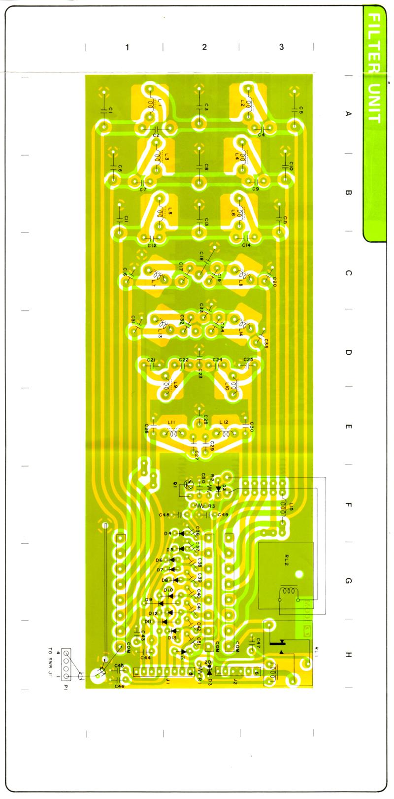
3 PROCEDURE Q1 RL2 L15 C49 D2 Figure 1. Filter Module prior to modification 1) Completely remove the existing rotary relay (RL2). Be careful to leave all other existing components intact. Save the 2 longer brass tubing sections for later use. Figure 2. Brass tubing from rotary relay 2) Remove D2 and C49. 3) Remove Q1 and replace with a 2N2222A. Be sure to accommodate the different pin-out of the two transistors. The collector pin is the middle hole. 4) Remove L15 carefully. This inductor will be moved elsewhere to make room for a relay board. With an insulated piece of wire place on the bottom of the PCB, make a shorting connection to complete the former path of L15. 5) Make a notch in PCB trace as shown in Figure 3. Clear top of PCB on both sides of the notch to expose bare copper on PCB. L15 will be soldered here. 6) Install L15 as shown in Figure 4.

 Perform the modification to bottom side of PCB as shown in")

4 CUT NOTCH IN TRACE Figure 3. Notch made in PCB trace to accommodate new placement of L15. Figure 4. L15 installed in new position. 7) Perform the modification to bottom side of PCB as shown in Figure 5. A trace will be cut, and one of the resulting sides will be bridged to the ground. This will be used as the ground connection hole for the soon to be constructed control board.


5 CUT NOTCH IN TRACE BRIDGE TO GROUND Figure 5. Original condition of PCB compared to modified version. The entire schematic of the completed project is shown in Figure 6. The circuitry inside the dotted rectangles is constructed for this project. The circuitry outside the dotted rectangles is the original Icom circuitry minus the components removed in steps 1 thru 3. Pictures of the final project are shown in Figures 7 and 8.


6 BOARD #3 RL9 BOARD #2 RL2 D D C TO Q3 TO Q4 TO Q5 TO Q6 E RL10 RL11 RL12 G H I J K N O P Q R RL3 RL4 RL5 TO Q3 TO Q4 D TO Q5 TO Q6 7.5V F BOARD #1.1 uf 4.7 uf VCC Q0 Q1 Q2 10k Q3 10k Q4 14 CLK Q5 Q6 13 ENA Q7 8 Q2 GND RST 2N2222A TO RL2 & RL9 Q3 2N7000 TO RL3 & RL10 Q4 2N7000 TO RL4 & RL11 Q5 2N C RL13 L S RL6 C TO RL8 & RL15 TO RL5 & RL12 B TO Q7 M T TO Q7 Q9 2N7000 Q6 2N7000 B RL14 RL7 TO RL7 & RL14 Q8 2N7000 TO RL6 & RL13 Q7 2N7000 B TO Q8 TO Q8 A RL15 RL8 A TO Q9 TO Q9 A Figure 6. Schematic of completed filter module. Areas in dotted rectangles are added circuitry

7 Board #3 Board #1 Board #2 Figure 7. Completed filter project top view. RL15 RL8 RL7 RL6 RL5 RL4 RL3 RL14 RL13 RL12 RL11 RL10 RL9 RL2 Figure 8. Completed filter project side view.


8 8) Construct and install Board #1. This board is constructed on perf-board with 100 mil spacing. An IC socket is highly recommended. Refer to Figure 9 for reference. The 3 stiff metal pins holding up the board at points B,C and F are from wire wrap pins. An insulator is placed between the bottom of the board and the top of the existing circuitry below it. The other wires connecting to the PCB are 22AWG solid wire. Include sufficient length wires from the drain of each transistor to reach each relay. The test points in Figures 9 and 10 correspond to the test points in the schematic. F C B 7.5V GND /RL Figure 9. Board #1 (Control Board).


9 E M L K J I H G F D T S R Q P O N A C B Figure 10. Test Point positions. These correspond to schematic in Figure 6. 9) Construct Board #3. Refer to Figure 11 for details. Leave adequate room on the sides of the board for the mounting screws. Cut the brass tubing from the original relay to the width of the new relays. These are used as standoffs to retain the boards as shown in Figures 7 and 8. #4 screws fit perfectly inside of the tubing. Drill holes through the sides of the module as required to retain the board. Solder sections of enameled wire adequate to reach the proper destination on the circuit board. These enamel wires are not shown on Figure ) Place Board #3 inside the module as shown in Figures 7 and 8. This is a tight fit, so be careful. Attach all of the wires to the proper points on the PCB. This will require some planning before installation. In my case, the wires to Points E and M were toward the end of the module with the loose gray cable. Points L and K were soldered immediately in front of the board to the PCB below. Points G, H, I and J were soldered as shown in ) Construct and install Board #2 in an analogous fashion to that of board #3. Note the different mounting requirements for the standoffs. This will result in a gap in the middle of Board #2 between relays and no screw at the end of one board. This is necessary because of the large hole in the module to accommodate the former rotary relay. The added extra complexity of this mounting is rewarded by the extra space available on this side of the module. Figure 13 shows a close-up of he wiring of points D,T S, and R


10 Attach Enameled wire to points G thru M GND RF from TP E M L K J I H G Diodes +12V from point A Brass tubing standoff with 4-40 screw Figure 11. Front and back view of Board #3. Point N Point O Point P Point G Point H Point Q Figure 12. Close-up showing wiring of the ends of the relay boards Point I Point J
 The modification is now complete. Test for basic problems like shorts between points A, B, C, and F. If there are no shorts, the circuit should be safe.")
 Turn on the radio, and you should hear one single, relatively quiet click from the relay module. If you hear non stop clicking, there is a problem. If all is well, press the up/down band buttons.")
11 Figure 13. Close-up of wiring for points D,T S, and R of Board #2 12) Solder the wires from the transistors on Board #1 to the appropriate diodes on the relay boards. 13) The modification is now complete. Test for basic problems like shorts between points A, B, C, and F. If there are no shorts, the circuit should be safe. A basic test can be accomplished without total installation in the radio. With radio power off, connect J1 to the corresponding P16 in the radio. Be absolutely certain of correct orientation of J1. 14) Turn on the radio, and you should hear one single, relatively quiet click from the relay module. If you hear non stop clicking, there is a problem. If all is well, press the up/down band buttons. You should have some clicks where the old rotary relay used to chatter loudly, and then the clicking should stop. If all seems well, fully install the module in the radio and try it out. TROUBLESHOOTING Any troubleshooting will require a basic understanding of how the circuit works. In the original circuit, the rotary relay had three poles. Two of the poles were used to place the selected low pass filter in the circuit. The third pole was used for feedback to the microprocessor for position information of the rotary relay. There were seven separate positions in the rotary relay, corresponding to the seven different low pass filters that were switched. The position info from the third pole of the relay routed the 7.5 volts from the zener regulator into the diode matrix formed by D4-D13. Output from the diode matrix provide binary data on the 4 bit bus (L1,L2,L4 and L8) for position information. The 1 of 7 high output signal formerly provided by the rotary relay
12 is now provided by the 4017 counter outputs. The pulse that formerly caused Q1 to advance the relay one position is now used to cause the counter to advance one count. The counter is decoded internally and 10 outputs provided. In this implementation, the 8 th count is used to reset the counter so that it cycles back to output #1 being high. The single high output will remain high until a pulse advances the counter, at which time another output will go high. These outputs drive both the diode matrix and the gate of a MOSFET. A high signal on the MOSFET gate will turn it on and effectively ground one side of the connected relays. This performs the same function as the rotary relay without the noise, oxidation, and alignment issues. If the problem seems to be that the relays never stop chattering, that means the proper position information in not getting to the microprocessor. Verify that each output of the counter (Q0-Q6) has a high pulse, and that the pulse is reaching the diode matrix properly. If the symptoms are that you don t hear any relay clicking, even when changing the bands, it is likely that there is a problem with the pulse getting to the counter. Verify the presence of a pulse at pin 14 of the 4017 while changing bands. If there is a pulse there, verify one of the outputs of the counter is high, and that the corresponding relays are being grounded. If they are being grounded, confirm 12V is present on the other side of the relay coil. If there is no pulse at pin 14 of the 4017 while changing bands, confirm he presence of a pulse at the RL pin of J1. If there is no pulse there, verify that it is there with the module disconnected from J1. If it is not there without the module connected, then the problem is outside the module. If it is there, the module is loading it down when connected. Assuming the pulse is at the RL pin of J1, the problem must be in the Q1 or Q2 circuitry. If the relays sound right when clicking, but there is low sensitivity in the receive and high collector current during transmit, either a relay is failing to key or some of the filter wiring is incorrect. Fortunately the low pass filters are DC shorts from input to output. The operation of the relays can be conducted with just J1 connected and the module out of the radio. For any given band, the proper connections can be tested for continuity between the SWR1 pin of P1 and the RA0 pin of J2. These points are clearly visible on the schematic on Figure 6. During proper operation, there should be low resistance continuity between those two pins. Referring the schematic on Figure 6 and using the 1.8 MHz low pass filter as an example, Pin 3 of the 4017 should be high. This should produce a high L1 on J1, with L2, L4, and L8 all low. The high level on pin 3 of the 4017 should also turn on Q3, which in turn should drive the coil of RL2 and RL9 low. This should key both RL2 and RLY 9, resulting in continuity between SWR1 and RA0. If there is not, going from left to right on the schematic, there should be continuity between SWR1 and the enameled wire on relay 9. Continuing, there should be continuity between SWR1 and points G and N. Continuing, there should be continuity between SWR1 and the enameled wire on RL9. If the continuity is not present, either the relay is not keying, or the wiring is going to an incorrect relay.
13 Figure 14. Schematic of original concept by F5IKI.
14 Figure 15. Schematic showing modifications to F5IKIs design by IW9HGS.
15
SIMPLE DIRECT DRIVE DESULPHATOR/ DESULFATOR KIT INSTRUCTIONS
 SIMPLE DIRECT DRIVE DESULPHATOR/ DESULFATOR KIT INSTRUCTIONS Parts List C1 470uF/ 25V 1off C2 C5 0.1uF/ 50V 4off C6 C9 0.01uF/ 50V 4off D1 12V/ 1.3W zener 1off Q1 2N2907 1off Q2 Q4 IRFB3307 3off R1 510R/
IPR LA-3 KIT last update 15 march 06
 IPR LA-3 KIT last update 15 march 06 PART-2: Audio Circuitry CIRCUIT BOARD LAYOUT: Power and Ground Distribution Now that your power supply is functional, it s time to think about how that power will be
KN-Q10 Assembly Manual
 KN-Q10 Assembly Manual Translated by Adam Rong, BD6CR/4 with permission from Ke Shi, BA6BF Edited by Stephen, VK2RH Revision B, Oct 14, 2010 Thank you for purchasing the KN-Q10 4 Band SSB/CW Dual Mode
1 Second Time Base From Crystal Oscillator
 1 Second Time Base From Crystal Oscillator The schematic below illustrates dividing a crystal oscillator signal by the crystal frequency to obtain an accurate (0.01%) 1 second time base. Two cascaded 12
INSTALLATION MANUAL FOR 2U EXTENDED FREQUENCY RANGE MODIFICATION KIT
 FOR 2U57- EXTENDED FREQUENCY RANGE MODIFICATION KIT Kit for modification of ARC Type 38A Communication System; (Extended COM Frequency Range: 8. to 36.975 MHz) Part Number Change: From: To: RT-38A - Standard:
Assembly and Operating Instructions. Revision D, Aug. 20, Copyright 2002, Elecraft; All Rights Reserved
 Introduction E L E C R A F T K N B N O I S E B L A N K E R Assembly and Operating Instructions Revision D, Aug. 0, 00. Copyright 00, Elecraft; All Rights Reserved The KNB noise blanker can be used to suppress
KK1L Icom Band Decoder Basic Assembly
 KK1L Icom Band Decoder Basic Assembly Ronald Rossi, KK1L http://home.comcast.net/~kk1l Features: RFI isolated inputs Fully opto-isolated Replaces one BCD band decode port on KK1L dual decoder Description:
IR add-on module circuit board assembly - Jeffrey La Favre January 27, 2015
 IR add-on module circuit board assembly - Jeffrey La Favre January 27, 2015 1 2 For the main circuits of the line following robot you soldered electronic components on a printed circuit board (PCB). The
5v AC R. 12v. 1kohm. F=35KHz oscilloscope. 3 Final Project OFF. ON Toggle Switch. Relay 5v 2N3906 2N uF LM311. IR Detector +5v GND LED PNP NPN
 3 Final Project Diode 103 IR Detector OFF ON Toggle Switch IR Detector +5v Push Button IR 100uF LED + GND LDR C Preset R 7805 IN GND OUT Relay 5v + PNP 2N3906 1 Kohm NPN 2N3904 4 3 2 1 555 5 6 7 8 4 3
V6.2 SoftRock Lite Builder s Notes. November 17, 2006
 V6.2 SoftRock Lite Builder s Notes November 17, 2006 Be sure to use a grounded tip soldering iron in building the v6.2 SoftRock circuit board. The soldering iron needs to have a small tip, (0.05-0.1 inch
SoftRock v6.0 Builder s Notes. May 22, 2006
 SoftRock v6.0 Builder s Notes May 22, 2006 Be sure to use a grounded tip soldering iron in building the v6.0 SoftRock circuit board. The soldering iron needs to have a small tip, (0.05-0.1 inch diameter),
Pacific Antenna Easy TR Switch
 Pacific Antenna Easy TR Switch Kit Description The Easy TR Switch is an RF sensing circuit with a double pole double throw relay that can be used to automatically switch an antenna between a separate receiver
Construction Manual 4m-Linear-Transverter XV4-15
 Construction Manual 4m-Linear-Transverter XV4-15 Holger Eckardt DF2FQ Kirchstockacherstr. 33 D-85662 Hohenbrunn 3207 Technical data exciter frequency: 21.0... 21.5 MHz RF frequency: 70.0.. 70.5 MHz supply
LBI-38392C IC DATA MAINTENANCE MANUAL LOGIC BOARD U707 OCTAL DATA LATCH 19D902172G1 & G2 TABLE OF CONTENTS
 LBI-38392C MAINTENANCE MANUAL LOGIC BOARD 19D902172G1 & G2 U707 OCTAL DATA LATCH IC DATA TABLE OF CONTENTS Page DESCRIPTION........................................... Front.. Cover CIRCUIT ANALYSIS........................................
Never power this piano with anything other than a standard 9V battery!
 Welcome to the exciting world of Digital Electronics! Who is this kit intended for? This kit is intended for anyone from ages 13 and above and assumes no previous knowledge in the field of hobby electronics.
Flexible Amplifier QSK Keying Interface: Add Turn-Off Delay, and Low-Current Ground or +12V Keying Phil Salas AD5X
 Flexible Amplifier QSK Keying Interface: Add Turn-Off Delay, and Low-Current Ground or +12V Keying Phil Salas AD5X Introduction As a CW operator, I enjoy QSK operation with my ALS-600 amplifier (see the
SoftRock v6.0 Builder s Notes. April 6, 2006
 SoftRock v6.0 Builder s Notes April 6, 006 Be sure to use a grounded tip soldering iron in building the v6.0 SoftRock circuit board. The soldering iron needs to have a small tip, (0.05-0. inch diameter),
EVDP610 IXDP610 Digital PWM Controller IC Evaluation Board
 IXDP610 Digital PWM Controller IC Evaluation Board General Description The IXDP610 Digital Pulse Width Modulator (DPWM) is a programmable CMOS LSI device, which accepts digital pulse width data from a
MAINTENANCE MANUAL AUDIO MATRIX BOARD P29/
 MAINTENANCE MANUAL AUDIO MATRIX BOARD P29/5000056000 TABLE OF CONTENTS Page DESCRIPTION................................................ Front Cover CIRCUIT ANALYSIS.............................................
Contents. Acknowledgments. About the Author
 Contents Figures Tables Preface xi vii xiii Acknowledgments About the Author xv xvii Chapter 1. Basic Mathematics 1 Addition 1 Subtraction 2 Multiplication 2 Division 3 Exponents 3 Equations 5 Subscripts
DESIGN ~ND CONSTRUCTION OF ~ STEP ETCHING INSTRUMENT ~BSTR~CT
 DESIGN ~ND CONSTRUCTION OF ~ STEP ETCHING INSTRUMENT I NTRODUCT ION Robert L. Crandall 5th Year Microelectronic Engineering Student Rochester Institute of Technology ~BSTR~CT ~n instrument was designed
DC Motor-Driver H-Bridge Circuit
 Page 1 of 9 David Cook ROBOT ROOM home projects contact copyright & disclaimer books links DC Motor-Driver H-Bridge Circuit Physical motion of some form helps differentiate a robot from a computer. It
HW-8-TR V3 PARTS LIST
 HW-8-TR V3 PARTS LIST Qty Ref Description Markings 4C2 C3 C4 C5 Capacitor Disc.1ls.1uF 104 1 C1 Capacitor Disc.2ls.1uF 100V 104 1 QSKMOD-C92 Capacitor Electrolytic 1uF 50V 1 QSKMOD Capacitor Mylar.47uF
QUASAR PROJECT KIT # /24 HOUR GIANT CLOCK
 This project was originally published in the electronics magazine, Silicon Chip, a few years ago. It is issued here as a kit with permission. Some modifications to the original published circuit and software
Bill of Materials: PWM Stepper Motor Driver PART NO
 PWM Stepper Motor Driver PART NO. 2183816 Control a stepper motor using this circuit and a servo PWM signal from an R/C controller, arduino, or microcontroller. Onboard circuitry limits winding current,
Construction Manual 6m-Linear-Transverter XV6/10
 Construction Manual 6m-Linear-Transverter XV6/10 Holger Eckardt DF2FQ Kirchstockacherstr. 33 D-85662 Hohenbrunn 2606 Technical data exciter frequency: 28... 30 MHz RF frequency: 50... 52 MHz supply voltage:
Getting Started in Eagle Professional Schematic Software. Tyler Borysiak Team 9 Manager
 Getting Started in Eagle 7.3.0 Professional Schematic Software Tyler Borysiak Team 9 Manager 1 Executive Summary PCBs, or Printed Circuit Boards, are all around us. Almost every single piece of electrical
o What happens if S1 and S2 or S3 and S4 are closed simultaneously? o Perform Motor Control, H-Bridges LAB 2 H-Bridges with SPST Switches
 Cornerstone Electronics Technology and Robotics II H-Bridges and Electronic Motor Control 4 Hour Class Administration: o Prayer o Debriefing Botball competition Four States of a DC Motor with Terminals
DIODE / TRANSISTOR TESTER KIT
 DIODE / TRANSISTOR TESTER KIT MODEL DT-100K Assembly and Instruction Manual Elenco Electronics, Inc. Copyright 1988 Elenco Electronics, Inc. Revised 2002 REV-K 753110 DT-100 PARTS LIST If you are a student,
TK-931 Receiver Modifications
 TK-931 Receiver Modifications This page identifies all the hardware modifications necessary to adapt a Kenwood TK-931 transceiver for 902 MHz repeater receive operation. Not shown here is the effort required
FEB User s Guide Power Factor Corrected 500W Off-Line Power Supply
 FEB108-001 User s Guide Power Factor Corrected 500W Off-Line Power Supply Featured Fairchild Product: FAN4810 www.fairchildsemi.com/febsupport Contents 1. General Board Description...3 1.1 Contents of
Hendricks QRP Kits The Twofer Rev
 Hendricks QRP Kits The Twofer Rev 1 11-15-06 1. Description The Twofer is a classic QRP transmitter that s easy to assemble and operate. It uses a JFET VXO (variable crystal oscillator), driver stage and
555 Morse Code Practice Oscillator Kit (draft 1.1)
") This kit was designed to be assembled in about 30 minutes and accomplish the following learning goals: 1. Learn to associate schematic symbols with actual electronic components; 2. Provide a little experience
This kit was designed to be assembled in about 30 minutes and accomplish the following learning goals: 1. Learn to associate schematic symbols with actual electronic components; 2. Provide a little experience
Controlling 280 Turnout Servos Using Small Push-Button Fascia Panels
 Controlling 280 Turnout Servos Using Small Push-Button Fascia Panels By Bob Judge and Al Zimmerschied NMRA 2015 National Convention Portland Oregon August 23-29, 2015 1 Forced to move, the Boeing Employees
Building a Bitx20 Version 3
 Building a Bitx20 Version 3 The board can be broken into sections and then built and tested one section at a time. This will make troubleshooting easier as any problems will be confined to one small section.
Semiconductors, ICs and Digital Fundamentals
 Semiconductors, ICs and Digital Fundamentals The Diode The semiconductor phenomena. Diode performance with ac and dc currents. Diode types: General purpose LED Zener The Diode The semiconductor phenomena
Pacific Antenna - Easy TR Switch
 Pacific Antenna - Easy TR Switch Kit Description The Easy TR Switch is an RF sensing switch that can be used to switch an antenna between a receiver and transmitter. It also has a second switched pair
Circuit Board Assembly Instructions for Babuinobot 1.0
 Circuit Board Assembly Instructions for Babuinobot 1.0 Brett Nelson January 2010 1 Features Sensor4 input Sensor3 input Sensor2 input 5v power bus Sensor1 input Do not exceed 5v Ground power bus Programming
Line-Following Robot
 1 Line-Following Robot Printed Circuit Board Assembly Jeffrey La Favre October 5, 2014 After you have learned to solder, you are ready to start the assembly of your robot. The assembly will be divided
Phys Lecture 3. Power circuits how to control your motors Noise and Shielding
 Phys 253 - Lecture 3 Power circuits how to control your motors Noise and Shielding Digital-to-Analog Conversion PWM 2 D/A Conversion and power circuits When would you like to produce an output signal that
Lightning Detector 1.0
 Lightning Detector 1.0 Instruction Manual Eastern Voltage Research, LLC January 2017, REV A 1 http://www.easternvoltageresearch.com SAFETY DISCLAIMER THIS KIT IS FOR HOBBY / NOVELTY USE ONLY. IT IS NOT
Technician Licensing Class T6
 Technician Licensing Class T6 Amateur Radio Course Monroe EMS Building Monroe, Utah January 11/18, 2014 January 22, 2014 Testing Session Valid dates: July 1, 2010 June 30, 2014 Amateur Radio Technician
Workshop Part Identification Lecture N I A G A R A C O L L E G E T E C H N O L O G Y D E P T.
 Workshop Part Identification Lecture N I A G A R A C O L L E G E T E C H N O L O G Y D E P T. Identifying Resistors Resistors can be either fixed or variable. The variable kind are called potentiometers
4.2.2 Metal Oxide Semiconductor Field Effect Transistor (MOSFET)
") 4.2.2 Metal Oxide Semiconductor Field Effect Transistor (MOSFET) The Metal Oxide Semitonductor Field Effect Transistor (MOSFET) has two modes of operation, the depletion mode, and the enhancement mode.
4.2.2 Metal Oxide Semiconductor Field Effect Transistor (MOSFET) The Metal Oxide Semitonductor Field Effect Transistor (MOSFET) has two modes of operation, the depletion mode, and the enhancement mode.
Electronics: Design and Build Training Session. Presented By: Dr. Shakti Singh Hazem Elgabra Amna Siddiqui
 Electronics: Design and Build Training Session Presented By: Dr. Shakti Singh Hazem Elgabra Amna Siddiqui Basic prototyping and measurement tools Breadboard basics Back View VCC GND VSS Breadboard basics
Troubleshooting SENET SENET
 SENET SENET is IGT s main I/O method for dealing with simple Input and Outputs. Most game designers take a straight forward process of Parallel I/O ports. Williams is known for its matrix of Row and Column
A Repeater for the NCE Radio System By Mark Schutzer January 6, 2005
 A Repeater for the NCE Radio System By Mark Schutzer January, 00 Introduction: This is a follow on to my earlier write up that described a diversity receiver for the NCE radio system. In this write up
DIODE / TRANSISTOR TESTER KIT
 DIODE / TRANSISTOR TESTER KIT MODEL DT-100K 99 Washington Street Melrose, MA 02176 Phone 781-665-1400 Toll Free 1-800-517-8431 Visit us at www.testequipmentdepot.com Assembly and Instruction Manual Elenco
DIY KIT 141. Multi-Mode Timer
 INTRODUCTION No one can call themselves an electronics hobbyist unless they have built a timer. There are many tens of designs using a variety of new and sometimes old circuits. Witness the longest surviving
ALX-SSB 5 Band Filter Assembly Manual 19 November 2018
 ALX-SSB 5 Band Filter Assembly Manual 19 November 2018 Contents Theory of Operation:... 1 Figure 1... 2 Parts Included:... 4 Board Overview:... 5 Figure 2... 5 Figure 3... 5 Board Assembly:... 6 Cable
build info nonlinearcircuits
 It s 555 resonator build info nonlinearcircuits BOM BC547 10 npn marked n on PCB see notes BC557 10 pnp- marked p on PCB see notes 555 IC 5 TL072 2 TL074 1 power connector 0.156 1 Molex 3 pin 100k pots
Bi-Directional DC Motor Speed Controller 5-32Vdc (3166v2)
") General Guidelines for Electronic Kits and Assembled Modules Thank you for choosing one of our products. Please take some time to carefully read the important information below concerning use of this product.
General Guidelines for Electronic Kits and Assembled Modules Thank you for choosing one of our products. Please take some time to carefully read the important information below concerning use of this product.
How to build a Cracklebox. Red Wierenga Brooklyn College Center for Computer Music October 13, 2015
 How to build a Cracklebox Red Wierenga Brooklyn College Center for Computer Music October 13, 2015 What s a Cracklebox? What s a Cracklebox? The Cracklebox was developed by Michel Waisvisz and others at
ECE 2010 Laboratory # 5 J.P.O Rourke
 ECE 21 Laboratory # 5 J.P.O Rourke Prelab: Simulate the circuit used in parts 1 and 2 of the Lab and record the simulated results. Your Prelab is due at the beginning of lab and will be checked off by
ABC V1.0 ASSEMBLY IMPORTANT!
 ABC V1.0 ASSEMBLY Before starting this kit, prepare the following tools: Soldering iron (15-20W will do), flush cutters, no.2 hex screwdriver or allen key and phillips screwdriver. Also briefly go through
High Current MOSFET Toggle Switch with Debounced Push Button
 Set/Reset Flip Flop This is an example of a set/reset flip flop using discrete components. When power is applied, only one of the transistors will conduct causing the other to remain off. The conducting
Maintenance Manual CHANNEL GUARD ENCODER/DECODER 19D430740G1 TONE REJECT FILTER 19D430740G4. Mobile Communications
 E ********* (REPLACES LBI-4143) Mobile Communications CHANNEL GUARD ENCODER/DECODER 19D430740G1 TONE REJECT FILTER 19D430740G4 Printed in U.S.A. Maintenance Manual TABLE OF CONTENTS SPECIFICATIONS..................................................
BASIC-Tiger Application Note No. 059 Rev Motor control with H bridges. Gunther Zielosko. 1. Introduction
 Motor control with H bridges Gunther Zielosko 1. Introduction Controlling rather small DC motors using micro controllers as e.g. BASIC-Tiger are one of the more common applications of those useful helpers.
IXRFD615X2 Application Note Full-Bridge Resonant Generator
 IXRFD615X2 Application Note RF Power Capabilities of the IXRFD615X2 MOSFET Gate Driver in a Resonant Full-Bridge Configuration Gilbert Bates IXYS Colorado Abstract The IXRFD615X2 dual 15 A MOSFET driver
ANALOG TO DIGITAL CONVERTER
 Final Project ANALOG TO DIGITAL CONVERTER As preparation for the laboratory, examine the final circuit diagram at the end of these notes and write a brief plan for the project, including a list of the
Conventional transistor overview and special transistors
 Conventional transistor overview and special transistors This worksheet and all related files are licensed under the Creative Commons Attribution License, version 1.0. To view a copy of this license, visit
16 Multiplexers and De-multiplexers using gates and ICs. (74150, 74154)
") 16 Multiplexers and De-multiplexers using gates and ICs. (74150, 74154) Aim: To design multiplexers and De-multiplexers using gates and ICs. (74150, 74154) Components required: Digital IC Trainer kit,
16 Multiplexers and De-multiplexers using gates and ICs. (74150, 74154) Aim: To design multiplexers and De-multiplexers using gates and ICs. (74150, 74154) Components required: Digital IC Trainer kit,
The Infinity Bug. This is an amazing project... Order kit Fully assembled version $199 Order Infinity Bug
 The Infinity Bug This is an amazing project... us$55.00 plus $6.50 post Order kit Fully assembled version $199 Order Infinity Bug The INFINITY BUG is connected across the phone-line of a distant phone
IC-765: Installing the Inrad Roofing Filter Mod
 IC-765: Installing the Inrad Roofing Filter Mod The Icom IC-765 roofing filter mod consists of a 6-pole, 4 khz wide filter followed by a high dynamic range, feedback amplifier. The amplifier provides enough
Read This Page First
 Read This Page First If you are reading this you know the manuals are always available at QRPKITS.com. If you have questions contact qrpkits.com@gmail.com There is no need to print out the whole assembly
Project: Electromagnetic Ring Launcher
 Project: Electromagnetic Ring Launcher Introduction: In science museums and physics-classrooms an experiment is very commonly demonstrated called the Jumping Ring or Electromagnetic Ring Launcher. The
LBI-39061A. Installation Manual. DTMF Encoder 344A4209P23 (MHDE5U) ericssonz
 ericssonz") LBI-39061A Installation Manual DTMF Encoder 344A4209P23 (MHDE5U) ericssonz TABLE OF CONTENTS Page INTRODUCTION...3 GENERAL DESCRIPTION...3 PROGRAMMING...3 THEORY OF OPERATION...3 INSTALLATION AND ALIGNMENT...4
LBI-39061A Installation Manual DTMF Encoder 344A4209P23 (MHDE5U) ericssonz TABLE OF CONTENTS Page INTRODUCTION...3 GENERAL DESCRIPTION...3 PROGRAMMING...3 THEORY OF OPERATION...3 INSTALLATION AND ALIGNMENT...4
Treetop Circuits Owner s Manual for SB-SB-600 Adapter Version 1
 The SB-600 SSB adapter from Treetop Circuits (Fig. 1) is designed specifically as an accessory to the Hammarlund SP-600 series of receivers. It provides enhanced performance on SSB and CW signals, using
SoftRock v5.0 Builder s Notes. December 12, Building a QSD Kit
 SoftRock v5.0 Builder s Notes December 12, 2005 Building a QSD Kit Be sure to use a grounded tip soldering iron in building the QSD board. The soldering iron needs to have a small tip, (0.05-0.1 inch diameter),
Low Voltage, High Current Time Delay Circuit
 Low Voltage, High Current Time Delay Circuit In this circuit a LM339 quad voltage comparator is used to generate a time delay and control a high current output at low voltage. Approximatey 5 amps of current
T6A4. Electrical components; fixed and variable resistors, capacitors, and inductors; fuses, switches, batteries
 Amateur Radio Technician Class Element Course Presentation ti ELEMENT SUB-ELEMENTS Technician Licensing Class Supplement T Electrical/Electronic Components Exam Questions, Groups T - FCC Rules, descriptions
Handy dandy little circuit #17 #17
 Handy dandy little circuit #17 #17 Download # 17 in PDF There are a lot of alarm systems on the market but you might be inclined to build your own. This little project can be put together using inexpensive
Assembly Manual V1R2B-Rev1.0D
 Assembly Manual V1R2B-Rev1.0D for 4 State QRP MagicBox - Solid State Transmit/Receive System Designed by: Jim Kortge, K8IQY Copyright 2009-2012 - All rights reserved This system is the result of some brainstorming
ENGR-4300 Fall 2006 Project 3 Project 3 Build a 555-Timer
 ENGR-43 Fall 26 Project 3 Project 3 Build a 555-Timer For this project, each team, (do this as team of 4,) will simulate and build an astable multivibrator. However, instead of using the 555 timer chip,
DC Injector (Bias Tee) kit. Technical Manual
 kit. Technical Manual") DC Injector (Bias Tee) kit Technical Manual Document Author Dave Powis, G4HUP Date 7 Jan 2017 Version Issue 2_0 Document Ref HUP-05-020 http://huprf.com Tel +44 (0)1473 737717 g4hup@outlook.com Contents
DC Injector (Bias Tee) kit Technical Manual Document Author Dave Powis, G4HUP Date 7 Jan 2017 Version Issue 2_0 Document Ref HUP-05-020 http://huprf.com Tel +44 (0)1473 737717 g4hup@outlook.com Contents
ericssonz LBI-38640E MAINTENANCE MANUAL FOR VHF TRANSMITTER SYNTHESIZER MODULE 19D902780G1 DESCRIPTION
 MAINTENANCE MANUAL FOR VHF TRANSMITTER SYNTHESIZER MODULE 19D902780G1 TABLE OF CONTENTS Page DESCRIPTION........................................... Front Cover GENERAL SPECIFICATIONS...................................
Fig 1: The symbol for a comparator
 INTRODUCTION A comparator is a device that compares two voltages or currents and switches its output to indicate which is larger. They are commonly used in devices such as They are commonly used in devices
Assembly Manual for VFO Board 2 August 2018
 Assembly Manual for VFO Board 2 August 2018 Parts list (Preliminary) Arduino 1 Arduino Pre-programmed 1 Faceplate Assorted Header Pins Full Board Rev A 10 104 capacitors 1 Rotary encode with switch 1 5-volt
Modifying The Heath HA-14 For 6 Meters Greg Chartrand - W7MY 4/22/07
 Introduction The Heathkit HA-14 was one of the few electron tube linear amplifiers intended for mobile use but few were purchased with the 12 volt mobile power supply. Most hams bought the HA-14 for base
LBI-31807D. Mobile Communications MASTR II REPEATER CONTROL PANEL 19B234871P1. Maintenance Manual. Printed in U.S.A.
 D Mobile Communications MASTR II REPEATER CONTROL PANEL 19B234871P1 Maintenance Manual Printed in U.S.A. This page intentionally left blank 13 PARTS LIST 12 PARTS LIST LBI-31807 11 PARTS LIST 10 SCHEMATIC
EE283 Electrical Measurement Laboratory Laboratory Exercise #7: Digital Counter
 EE283 Electrical Measurement Laboratory Laboratory Exercise #7: al Counter Objectives: 1. To familiarize students with sequential digital circuits. 2. To show how digital devices can be used for measurement
Practical 2P12 Semiconductor Devices
 Practical 2P12 Semiconductor Devices What you should learn from this practical Science This practical illustrates some points from the lecture courses on Semiconductor Materials and Semiconductor Devices
Interfacing the isppac-powr1208 with Modular DC-to-DC Converters
 with Modular s January 2003 Application Note AN6046 Introduction The isppac -POWR1208 is a single-chip, fully integrated solution to supervisory and control problems encountered when implementing on-board
Reading. Lecture 17: MOS transistors digital. Context. Digital techniques:
 Reading Lecture 17: MOS transistors digital Today we are going to look at the analog characteristics of simple digital devices, 5. 5.4 And following the midterm, we will cover PN diodes again in forward
N3ZI Kits General Coverage Receiver, Assembly & Operations Manual (For Jun 2011 PCB ) Version 3.33, Jan 2012
 Version 3.33, Jan 2012") N3ZI Kits General Coverage Receiver, Assembly & Operations Manual (For Jun 2011 PCB ) Version 3.33, Jan 2012 Thank you for purchasing my general coverage receiver kit. You can use the photo above as a
N3ZI Kits General Coverage Receiver, Assembly & Operations Manual (For Jun 2011 PCB ) Version 3.33, Jan 2012 Thank you for purchasing my general coverage receiver kit. You can use the photo above as a
R & D Electronics DIGITAL IC TRAINER. Model : DE-150. Feature: Object: Specification:
 DIGITAL IC TRAINER Model : DE-150 Object: To Study the Operation of Digital Logic ICs TTL and CMOS. To Study the All Gates, Flip-Flops, Counters etc. To Study the both the basic and advance digital electronics
University of Utah Electrical & Computer Engineering Department ECE 1250 Lab 4 Pulse Width Modulation Circuit
 University of Utah Electrical & Computer Engineering Department ECE 1250 Lab 4 Pulse Width Modulation Circuit Note: Bring textbook & parts used last time to lab. A. Stolp, 1/8/12 rev, Objective Build a
Supply Voltage Supervisor TL77xx Series. Author: Eilhard Haseloff
 Supply Voltage Supervisor TL77xx Series Author: Eilhard Haseloff Literature Number: SLVAE04 March 1997 i IMPORTANT NOTICE Texas Instruments (TI) reserves the right to make changes to its products or to
CS302 - Digital Logic Design Glossary By
 CS302 - Digital Logic Design Glossary By ABEL : Advanced Boolean Expression Language; a software compiler language for SPLD programming; a type of hardware description language (HDL) Adder : A digital
Calhoon MEBA Engineering School. Study Guide for Proficiency Testing Industrial Electronics
 Calhoon MEBA Engineering School Study Guide for Proficiency Testing Industrial Electronics January 0. Which factors affect the end-to-end resistance of a metallic conductor?. A waveform shows three complete
Product overview. Features. Product specifications. Order codes. 1kΩ Resistance Output Module
 Product overview The AX-ROM135 and the AX-ROM1000 Modules enable an Analogue, Pulse or Floating point signal and convert to either a 0-135Ω or a 1KΩ Proportional Resistive output signal. The output resistance
Name: Class: Date: 1. As more electronic systems have been designed using digital technology, devices have become smaller and less powerful.
 Name: Class: Date: DE Midterm Review 2 True/False Indicate whether the statement is true or false. 1. As more electronic systems have been designed using digital technology, devices have become smaller
Electrical, Electronic and Communications Engineering Technology/Technician CIP Task Grid
 Secondary Task List 100 SAFETY 101 Describe OSHA safety regulations. 102 Identify, select, and demonstrate proper hand tool use for electronics work. 103 Recognize the types and usages of fire extinguishers.
S-Pixie QRP Kit. Student Manual. Revision V 1-0
 S-Pixie QRP Kit Student Manual Revision V 1-0 Introduction The Pixie 2 is a small, versatile radio transceiver that is very popular with QRP (low power) amateur radio operators the world over. It reflects
CHAPTER 3 PROJECT METHODOLOGY
 CHAPTER 3 PROJECT METHODOLOGY 3.1 Introduction This chapter will cover the details explanation of methodology that is being used to make this project complete and working well. Many methodology or findings
PCB Design Guidelines for GPS chipset designs. Section 1. Section 2. Section 3. Section 4. Section 5
 PCB Design Guidelines for GPS chipset designs The main sections of this white paper are laid out follows: Section 1 Introduction Section 2 RF Design Issues Section 3 Sirf Receiver layout guidelines Section
Long Loopstick Antenna
 Long Loopstick Antenna Wound on a 3 foot length of PVC pipe, the long loopstick antenna was an experiment to try to improve AM radio reception without using a long wire or ground. It works fairly well
HAMTRONICS LPA 2-25R REPEATER POWER AMPLIFIER: ASSEMBLY, INSTALLATION, & MAINTENANCE
 HAMTRONICS LPA 2-25R REPEATER POWER AMPLIFIER: ASSEMBLY, INSTALLATION, & MAINTENANCE GENERAL INFORMATION. The Power Amplifier is a class C device designed to be installed as an integral part of a transmitter
ENGINEERING TRIPOS PART II A ELECTRICAL AND INFORMATION ENGINEERING TEACHING LABORATORY EXPERIMENT 3B2-B DIGITAL INTEGRATED CIRCUITS
 ENGINEERING TRIPOS PART II A ELECTRICAL AND INFORMATION ENGINEERING TEACHING LABORATORY EXPERIMENT 3B2-B DIGITAL INTEGRATED CIRCUITS OBJECTIVES : 1. To interpret data sheets supplied by the manufacturers
User s Manual. ACPL-339J Isolated Gate Driver Evaluation Board. Quick-Start. Testing Either Arm of The Half Bridge Inverter Driver (without IGBT)
") ACPL-339J Isolated Gate Driver Evaluation Board User s Manual Quick-Start Visual inspection is needed to ensure that the evaluation board is received in good condition. The default connections of the evaluation
ACPL-339J Isolated Gate Driver Evaluation Board User s Manual Quick-Start Visual inspection is needed to ensure that the evaluation board is received in good condition. The default connections of the evaluation