NATIONAL ADVISORY COMMITTEE FOR AERONAUTICS
|
|
|
- Raymond Page
- 5 years ago
- Views:
Transcription
1 _'x,'_l _ 3_+ tl / j' t...! "t <".;:. :; Z ' _... e, NATONAL ADVSORY COMMTTEE FOR AERONAUTCS TECHNCAL NOTE 2703 ELECTRCAL TECHNQUES FOR COMPENSATON OF THERMAL TME LAG OF THERMOCOUPLES AND RESSTANCE THERMOMETER ELEMENTS By Charles E. Shepard and sdore Warshawsky Lews Flght Propulson Laboratory Cleveland, Oho Washngton May 6, 1952 _",. _, g;71{:'_%:,
2
3 NATONAL ADVSORY COMMTTEE FOE AERONAUTCS TECHNCAL NOTE 2703 ELECTRCAL TECHNQUES FOR COMPENSATON OF Tfl_qMAL Go CO TME LAG OF THERMOCOUPLES AND RESSTANCE TEERMOMETER ELEMENTS By Charles E. Shepard and sdore Warshawsky SUMMARY Basc electrcal networks are descrbed that compensate for the thermal tme lag of thermocouple and resstance thermometer elements used n combuston research and n the control of jet power plants. The measurement or the detecton of rapd temperature changes by use of such elements can thereby be mproved. For a gven set of operatng condtons, networks requrng no amplfers can provde a thrtyfold reducton n effectve tme lag. Ths mprovement s obtaned wthout attenuaton of the voltage sgnal but results n a large reducton n the amount of electrc power avalable because of an ncrease n the output mpedance of the network. Networks usng commercally avalable amplfers can provde a thousandfold reducton n the effectve tme lag wthout attenuaton of the alternatng voltage sgnal or of the avalable electrc power, but the mprovement s often obtaned at the expense of loss of the zerofrequency sgnal. The completeness of compensaton s lmted by the extent of off-desgn operaton requred. NTRODUCT ON The control of jet engnes and the fundamental study of the dynamc combuston phenomena assocated wth such power plants nvolve the measurement of fluctuatng gas temperatures. When a thermocouple or resstance thermometer s used as the prmary element for such temperature measurements, the thermal lag of the element, caused by slow rate of heat transfer between the element and the surroundng gas, lmts the ablty of the element to follow such fluctuatons. The thermal lag s such that, as the frequency of the fluctuatons ncreases, the ampltude of the fluctuatons ndcated by the element decreases and also lags n tme behnd the true temperature. Sometmes t s possble to use a
4 2 NACA TN 2703 prmary element of suffcently small sze to acheve adequately rapd response. n many cases, however, such small elements have nsuffcent mechancal strength and nadequate servce lfe, so that larger elements wth apprecable lag must be employed. Snce the output of the prmary element s an electrc voltage_ electrcal networks can be used to compensate for the tme lag and the reducton n response ampltude and thereby to permt measurement of rapdly changng temperatures wth mproved fdelty. Compensaton of ths type, generally nvolvng specally desgned amplfers_ has been the bass of hot-wre anemometry (for example, references to 3) Such compensaton s also provded by the equalzng networks used n communcaton engneerng. Some basc networks that can be used ndvdually or n combnatons to compensate for the thermal lag of the prmary electrc thermometer elements used n jet engne operaton are descrbed heren. n those combnatons whch nclude amplfers_ the amplfers are of a sem-ndustral type, avalable commercally, and capable of extended use wthout adjustment or servce; n general, the compensatng network s desgned to correct for a gven amount of prmary-element thermal lag whch can be descrbed by a characterstc "tme constant" of the element. The magntude of ths tme constant s a functon of the mechancal desgn of the element and of the aerodynamc condtons n whch the element s used (reference A). Snce the compensaton employed s generally correct for only one set of aerodynamc condtons, the effects upon the performance of the compensated system of devatons from the desgn pont must be consdered. f the tme constant of the prmary element has been determned expermentally at one set of aerodynamc condtons_ t s generally possble to compute the tme constant at other sets of aerodynamc condtons and then to adjust the electrcal compensatng system for the new set of condtons. The nature of the response of the basc prmary element and the prncples of electrcal lag compensaton wll frst be revewed heren. Then_ after ntroducton of the operatonal termnology of the "transfer functon," several basc types of compensator crcut, both alone and n combnaton wth amplfers, wll be examned n detal. The next secton wll consder the effects of off-desgn operaton on performance. Fnally, the performance of two specfc assembles of apparatus wll be descrbed and ther partcular felds of usefulness ndcated. n the presentaton of compensatng crcuts, two basc forms of compensator_ the resstance-capactance (RC) and the resstance-nductance (RL) types, wll frst be descrbed_ together wth one smplfcaton of the RC type, the dfferentatng type. These compensators suffer from
5 1G NACA TN 2703 TABLE OF CONTENTS Page SUMMARY... NTRODUCTON... TME LAG COMPENSATOR NETWORKS... 3 Response of Prmary Element... 3 Dfferental equaton of prmary-element response... 3 Response to two smple types of gas temperature change... 3 Response n terms of voltage... Prncples of Electrcal Lag Compensaton... 5 Operatonal Termnology and the Transfer Functon... 5 Operatonal termnology... 5 Defnton of transfer functon... 7 Transfer functon of cascaded system... 7 Transfer functon of addtve system... 8 Combnaton of cascaded and addtve systems... 8 Compensatng Crcuts... 8 Termnology... 8 RC and EL compensatng crcuts wthout amplfer... 8 Effect of loadng on RC and RL compensators... 0 RC dfferentatng crcut used as compensator... ] RC and RL compensatng crcuts wth amplfers... A Amplfer nose... Transformer used as preamplfer Technques for mantanng d-c. response Negatve feedback amplfer Transformer used as compensator Effect of loadng on transformer-type compensator connected to sngle prmary element... e s to_.. 18 Effect of loadng on transformer-type comp n a _o_ected to two prmary elements Summary of Compensatng Systems ff-Desgn Performance Msmatch between tme constants of element and compensator Effect of ambent temperature on transformer-type compensator. 21 APPLCATONS... Example _ Example APPENDX A - SYMBOLS. 3O APPENDX B - TRANSFER FUNCTON OF TRANSFORMER APPENDX C - TRANSFER FUNCTON OF TRANSFORMER-TYPE COMPENSATOR REFERENCES... 37
6 NACA TN 2705 Page TABLES - EFFECT OF LOADNG ON RC AND RL COMPENSATORS MNMUM AMPLTUDE OF TEMPERA_ VARATON THAT CAN BE MEASURED BECAUSE OF NOSE LMTATON AT SGNAL-T0- NOSE RATO 04: EQUAL TO CHARACTERSTCS OF TP_NSFORMERS USED N REPRESENTATVE TRANSFORMER-TYPE COMPENSATORS... 4:O?O (N CO Co V - EFFECT OF CONNECTNG TP_NSFORMER-TYPE COMPENSATOR WTH SNGLE PRMARY ELEMENT TO PRMARY ELEMENT RESSTANCE R 1 AND TO LOAD RESSTANCE R k (a) T3rpe UTC/A (b) Type UTC/LS39... (_) T_e ADC/_ =2 4:5 4:4= V - EFFECT OF CONNECTNG TRANSFORMER-TYPE COMPENSATOR WTH TWO PRMARY ELEMENTS TO PRMARY ELEMENT RESSTANCE R AND LOAD RESSTANCE R (a) Type UTC/,A (b) Type UTC/LS (c) Type ADC/AX Vl - SUMMARY OF COMPENSATNG ELEMENTS... 4:5 4:6 4:7 4:8 V - SUMMARY OF COMPENSATNG SYSTEMS... 4:9 v - E_ECT OF_,NT OND-C. o_p_ of _SFO_-TYPE C0MPENSATOR (a) Type UTC/,A (b) Type UTC/,LS (c) Type ADc/Ax o X - PERFORMANCE OF COMPENSATNG SYSTEM OF FGURE 17(b) FOR VAROUS COMBNATONS OF R_ RC, AND C OF COMPENSATOR... 51
7 NACA TN co co a defcency n that the mprovement n effectve tme constant (and therefore n frequency response) s acheved only at the expense of a correspondng attenuaton of sgnal. The addton of an amplfer can correct for ths attenuaton. The amplfer ntroduces nose that tends to mask the sgnal_ however, the addton of a transformer as a preamplfer permts attanment of a more favorable sgnal-to-nose rato. A feedback amplfer can be desgned to combne the functons of amplfer and compensator. Fnally, there wll be descrbed another basc type of compensatng network, the transformer type, that combnes the functons of nose-free amplfer and of compensator. The analyss and results presented heren consttute a porton of a temperature measurements research program beng conducted at the NACA Lews laboratory. TME LAG COMPENSATOR NETWORKS Response of Prmary Element Dfferental equaton of prmary-element response. - f a thermocouple or a resstance thermometer element s subjected to a changng gas temperature T0(t), the tme rate of change dtl/dt of the element temperature Tl(t ) s proportonal to the temperature dfference (T O - T). Ths may be expressed (reference A) as T 1 (dt1/dt) = T O - T 1 or T 1 (dtl/dt) + T 1 = T O (1) where the factor of proportonalty T, the "tme constant," s characterstc of the element, of the gas propertes, and of the gas flow condtons. The value of the tme constant completely defnes the response of the element temperature to a changng gas temperature (All symbols used heren are defned n appendx A.) Response %o two smple types of gas temperature change. - The response characterstcs of the prmary element are vsualzed most smply by reference to fgure, whch descrbes the response to two types of nput change: (a) The curve of fgure l(a) shows that n response to a sudden "step change" AT 0 n gas temperature, the approach of the element temperatureto ts new value s along an exponental curve and covers 65 percent, 86 percent, 95 percent, and 98 percent of the nterval AT 0 n tme T, 2T, 3T_ and AT, respectvely.
8 A NACATN 2703 (b) n response to a steady snusodal varaton n gas temperature of ampltude T O and angular frequency _ the temperature of the prmary element wll oscllate wth reduced ampltude T and wll lag n phase and tme, as shown n fgure l(b). The value of the ampltude rato T1/T0 s shown n fgure l(c) as a functon of the angular frequency _. When _ = l/t1, the ampltude rato has dropped to 1/_. t s customary to term the response "flat" to the pont where _ = 1/T 1 and to term ths pont the "lmt" co co _O of response_ or the "cut-off pont." Curves of tme lag and phase lag are shown n fgure l(d) as a functon of angular frequency. When _ = /T, the tme lag s _T/_ and the phase lag s 45. The tme lag s substantally equal to T for _T 1 <. Response n terms of voltage. - The output emf e from a thermocouple or from a resstance-thermometer brdge can be represented as beng proportonal to the dfference between the temperature T 1 of t_e prmary element and some reference temperature T R such that el = Q( l - (2) For a thermocouple, T R s the "cold-juncton" temperature; for a resstance thermometer, TR s the "reference resstor" temperature. n the case of the thermocouple, Q s the thermoelectrc power; n the case of the resstance thermometer_ Q s the product of the temperature coeffcent of resstance of the thermometer element_ the voltage appled to the brdge, and a dmensonless functon of the brdge crcut resstances. A fcttous emf e 0 wll be defned as the equvalent emf that would be produced by a prmary element at a temperature S O e 0 = Q(T 0 - TR) (3) Substtutng equatons (2) and (3) nto equaton (1) yelds T1 (del/dt) + e = e 0
9 NACATN Prncples of Electrcal Lag Compensaton Electrcal lag compensaton could be produced f an electrcal network were found that could perform upon the prmary element output sgnal e the operatons descrbed by the left sde of equaton (A). The result so obtaned would be the voltage e0 representatve of the true gas temperature. bo 0,1 CO CO A network that approxmates the desred operatons s shown n fgure 2(a). Sutable choce of the elements R and C can produce a current through R proportonal to the tme dervatve of nput voltage; sutable choce of R C can produce an addtonal drect current through R proportonal to the nput voltage; by proper choce of the constants of proportonalty, the total current then flowng through R, and therefore the voltage across R, can be made approxmately proportonal to e0, as gven by equaton (A). A second network that approxmates the desred operaton s shown n fgure 2(b). Sutable choce of the elements R, RL, and L can produce a voltage across L approxmately proportonal to the tme dervatve of nput voltage and a voltage across R L proportonal to the nput voltage; by proper choce of the constants of proportonalty, the sum of the voltages across L and R L can be made approxmately g proportonal to eo, as gven by equaton (A). A thrd network that approxmates the desred operatonss shown n fgure 2(c). Sutable choce of the elements Rp, L, and N can produce a prmary current approxmately proportonal to nput voltage and a secondary emf proportonal to the tme dervatve of prmary current and therefore to the tme dervatve of nput voltage. Wth sutable choce of crcut constants, the autotransformer connecton can then produce the summaton requred by equaton (4). n order to establsh a mathematcal bass for such compensatng methods and for more complex refnements of the basc prncples and to defne the lmts of approxmaton, t s convenent to ntroduce the concept of the transfer functon. Operatonal Termnology and the Transfer Functon Operatonal termnology. - The response of the smple system represented by equaton () to an appled temperature T0(t ) of arbtrary form s gven by
10 6 NACA TN tll T1 = oc + e (TO/T1)dt (S) where c s a constant determned by the ntal value of T. However, t s more convenent for purposes of dscusson to present the soluton n a symbolc form wheren the symbol p replaces the dfferental operator d( )/dr of equaton (). Then the soluton of equatons () and CA) can be ndcated by CO co C_ 1 To (6a) T = + TP e 1 + Tlpeo (6b) t can be shown that, as long as p s multpled only by constants, t may be treated as an algebrac quantty where p represents d( )/dr, p2 represents d2( )/dr 2, /p represents y( )dt, and so forth (reference S). The usefulness of ths method of representaton s revealed by notng that () lnear dfferental equatons of more complex form than equaton(l) can be solved by the operatonal methods of Heavsde or Laplace, where the approprate operator replaces p_ and (2) that when e 0 s represented as a Fourer seres e 0 = Q(T - TO) = _' Bh sn (hoot - 8n) n=o 47) the soluton of such dfferental equatons s obtaned n complex representaton by formally replacng p by j_ (references 5 to 7). The ampltude rato, the tme lag, and the phase lag, at each angular frequency _, are then readly dervable. For the prmary element wth characterstc gven by equaton (6) and nput e 0 gven by equaton (7), the response e s m e = Q(T 1 - TO) = >_ Bn _----_0_ + n2_2t12 sn (hoot - 8n - qon) (8a) where _n = tan-1 (no T1) (8b)
11 2G NACA TN n order to take advantage of the convenence afforded by the operatonal termnology, all systems treated n ths report wll be assumed lnear. Defnton of transfer functon. - The dmensonless rato of the output quantty (expressed as a functon of p) dvded by the nput quantty (also expressed as a functon of p) s defned as the transfer functon Y(p) of a system obeyng a lnear dfferental equaton. From equaton (6) the transfer functon of the prmary element s 1 (9) Yl(p)- l+tlp The advantages of expressng the characterstcs of systems such as electrcal networks by means of transfer functons are (a) The equvalent transfer functon, and hence the response characterstcs, of a system composed of several elements can be obtaned from the transfer functons of the ndvdual elements by smple algebrac methods. (b) The response of a system havng a transfer functon Y(p) to an mpressed snusodal voltage E sn (_t-_) s [E sn (_t-_)] Y(j_), where j_ has been substtuted for the operator p. Transfer functon of cascaded system. - When several elements are joned n cascade as n fgure 5(a), that s, when the output of one element s fed nto the nput of the adjacent element, the resultant transfer functon s the product of the transfer functons of the ndvdual elements. f ths product s a constant, one transfer functon s sad to be the nverse of the others. As an example, f the prmary element output e gven by equaton (6b) s appled to an electrc network whose transfer functon s Y4(P) = (1/Adc)(l+TlP) (lo) where Adc s a constant (representng the attenuaton at zero frequency), the resultant product Y(p) Y4(p) wll be equal to /Adc, and the output e 4 wll be proportonal to the fcttous emf e 0 and hence to the appled temperature T O. Therefore, at all frequences at whch changes n T O may occur, e4 = (/Adc)e 0 ()
12 8 NACATN 2705 Networks that have transfer functons nverse to the prmary element over a lmted frequency range wll be descrbed under Compensatng Crcuts. These networks, n ther _orkng regon, have the transfer functon of equaton (lo). Transfer functon of addtve system. - f the outputs of several networks whch have a common nput are added as shown n fgure 3(b), the resultant transfer functon s equal to the sum of the transfer functons of the ndvdual networks. Combnaton of cascaded and addtve systems. - As an example, the arrangement of networks shown n fgure 5(c)_ wth the transfer functons of the varous networks as shown n the fgure, yelds an output emf e 2 equal to the nput emf e O. co co Compensatng Crcuts Termnology. - n followng paragraphs, varous compensatng systems wll be treated. These systems wll generally consst of basc components convenently desgnated transformers_ amplfers, compensators, and so on. The termnology s clarfed by the block dagram of fgure 4 whch shows the most common combnaton of components and the subscrpts assgned to the components, to the potental dfferences at ther termnals, and to the constants by whch they are characterzed. n ths fgure, the term "compensator" has been assgned to that component the chef functon of whch s to correct for the reducton n response ampltude of the prmary element wth ncreasng frequency of the appled temperature varaton. Unless specfcally ndcated otherwse, the termnology of fgure A wll apply to materal presented n subsequent paragraphs of ths dscusson of compensatng crcuts. Acompensatng system (ncludng one consstng of a sngle component) wll be characterzed chefly by two parameters: The frequencyresponse mprovement factor F s equal to the rato of the upper cutoff frequency of the compensated system to the upper cut-off frequency of the uncompensated prmary element; the over-all gan factor G s equal to the rato of the voltage output of the system (as t appears at the detector nput termnals) n the regon of flat frequency response to the equvalent electrc nput sgnal e 0 to the prmary element. RC and EL compensatng crcuts wthout amplfer. - Two basc networks whch approxmate the characterstc defned by equaton (0) are shown n fgures 2(a) and 2(b). The transfer functon of these compensators n the dealzed case of neglgble source mpedance and load admttance s
13 NACATN Y4(P) = l+(m 4/r) p where T$ and r are defned n fgure 2. The value of Y_(jco)l s shown n fgure 2(d). For the condton TA : T, where the compensator tme constant TA s equal to the prmary element tme constant T, co c_ co,co the product YA(p) Yl(p), whch descrbes the performance of a system consstng of the prmary element plus compensator n cascade, s /l\ YA(P) Y(P)=Jr) l+(t4/r)p (13) Ths equaton represents a lnear frst,order system, wth the effectve tme constant reduced by a factor of r from the value of T for the prmary element alone. For ths dealzed system, F = r and G = /r. The system has the followng addtonal characterstcs: (a) The response to a steady snusodal nput EO sn cot s a sne wave of ampltude Eo/[r _l+co 2 (TA/r) 2 ] and phase lag tan - (COTA/r). Ths response s shown n fgures 5(a) and 5(b). The range of "flat" response s extended by a factor F = r over that of a smple prmary element. The attenuaton of a zero frequency sgnal s Adc = /G = r. (b) The amount r by whch the frequency response can be mproved s lmted by the amount of ampltude attenuaton that can be tolerated. (c) The response to an mpressed step change of magntude _e 0 s descrbed by an exponental curve havng a tme constant Tl/r and a magntude of change Ae0/r (fg. 5(c)). Consequently, the mprovement n tme constant s accomplshed at the expense of a correspondng reducton n ampltude AeA of the output sgnal. (d) The maxmum value of tme constant whch can be compensated s determned by the components of the compensator. For the compensator of fgure 2(a), the RC network, the maxmum value of RcC offers no practcal lmtaton n the applcatons generally encountered. n the case of the RL network of fgure 2(b), the maxmumpossble value L/RL,m n of the tme constant (where RL,m n s the resstance of the nductor) s usually a functon of the weght of the nductor. For commercally avalable nductors, a value of L/RL,m n of 0.05 second s typcal for a weght of pound and the tme constant ncreases approxmately as the square root of the weght of the nductor.
14 0 NACATN 2703 (e) The output mpedance of the network vares wth frequency. For the RC network of fgure 2(a), the output mpedance has a maxmum value of approxmately R at zero frequency and approaches the resstance of the prmary element at very hgh frequences. The output mpedance of the RL network of fgure 2(b) has a mnmum value of approxmately RL at zero frequency and approaches R at very hgh frequences. Effect of loadng on RC and RL compensators. - The transfer functon gven n equaton (12) s derved for the condtons of a source of neglgble mpedance and a load of neglgble admttance. f a compensator of the type of fgure 2(a) or of fgure 2(b) s connected to a source of resstance R_ and to a load of resstance Rh (fg. 6), the effect s to change the form of the transfer functon. Although the value of T 4 s unchanged n all cases_ the factor by whch the d-c. sgnal s attenuated s no longer equal to r, nor does r any longer represent the factor by whch the frequency response s extended when the compensator s connected to a prmary element of tme constant T = T4. Under the condton of nonzero source resstance and fnte load resstance, the gan factor of the combnaton of compensator and prmary element wll be denoted G A and the factor by whch the frequency response sextended wll be denoted F&. The transfer functon s +T4p YA(P) = G4 +(TA/FA)P (12b) as compared wth equaton (12a) for the dealzed case. The changes n the quanttes (/G&) and F& are gven n table. The effect of addng a source resstance R_ and a load resstance Rh may be summarzed as follows: (a) For the RC compensator of fgure 6(a), the effect of keepng Rq = 0 and makng R_ fnte s to decrease G A and to ncrease F 4 n the same proporton. The effect of keepng Rk nfnte and makng R_ > 0 s to decrease both G 4 and F A. (b) For the EL compensator of f_gure 6(b), the effect of keepng R_ = 0 and makng Rh fnte s to decrease both G4 and F A. The effect of keepng Rh nfnte and makng R 0 s to decrease G 4 and to ncrease F A n the same proporton.... (c) The combned effect for both the RC and the RL compensators of makng R_ > 0 and Rh fnte s to decrease both G A and the product F4G4, so that the attenuaton s ncreased wthout a proportonate ncrease n frequency response mprovement factor. The relatons between GA and F 4 are_ for the RC compensator_
15 NACATN pc (14) F4 = G4 + PC where PC - RC DO (3O GO For the EL compensator, + PT F4 = G4 + PL (s) where R L PL = Rq RC dfferentatng crcut used as compensator. - A smplfed case of the RC compensator of fgure 2(a) s obtaned when the capactor shunt resstor R C s nfnte. The resultng transfer functon s T4'p Y4(P) - + T4'P (16) where T 4' = RC. Ths network s usually known as a dfferentatng crcut snce the dfferentatng functon s performed for the range of frequences n whch _ T 4' <. Ths network s also effectve n compensatng for the response of a prmary element n the hgh-frequency regon where _T >, provded that T 4' s chosen so that _T 4' <. t wll be noted that T 4' s no longer chosen equal to T. The ncrease n the upper frequency lmt s F = T/T 4' and ths factor also descrbes the reducton /G n sgnal ampltude for the operatng range. The dfferentatng crcut wll not pass the average value of the sgnal and therefore s useful only for measurng the alternatng components of the gas temperature n the frequency range RC and RL compensatng crcuts wth amplfers. - The compensatng crcuts just descrbed are defectve n that, although the effectve tme constant s reduced by a factor F (and the frequency range s correspondngly extended by the same factor), the ampltude of any
16 12 NACATN 2703 appled sgnal s attenuated by a factor /G that s equal to or greater than F. Ths defect can be remeded by the addton of an amplfer. f an amplfer the transfer functon of whch s Y3(p) s added to the crcut after the prmary element, as n fgure 7, the resultant transfer functon of the system wll be equal to the product YA(P) YS(P) Y(P)" The response of the system s descrbed for several possble condtons: co co (a) f the amplfer s a dstortonless d-c. amplfer (that s, one whch has a flat frequency response and lnear phase shft from zero frequency up to the maxmumfrequency where compensaton s to be acheved), the effects of the amplfer are an ncrease n the sgnal voltageequal to the voltage amplfcaton factor _5 of the amplfer, a constant shft n tme, and the ntroducton of a certan nose voltage. The magntude of the tme shft s neglgble n most practcal applcatons nvolvng temperature measurement; the problem of nose s dscussed n the secton Amplfer nose. The transfer functon of the amplfer-compensator combnaton s + TAp YA(P) Y3(P) = _3GA+(TJFA) p (17) For ths system, F = F A and G = _sga. (b) f the amplfer has a hgh-frequency cut-off pont (the pont at whch the amplfcaton factor s reduced by a factor /_) at = _3,b such that Y3(P) - l+p/ 3,b (s) where _3 s the voltage gan n the regon of flat response, then for the condton T A = T, the frequency response of the system correspondng to the transfer functon YA(P) Ys(P) Y(P) has the appearance shown n fgures S(a) and 8(b). When _5,b = FA/TA' the hgh-frequency cut-off pont s reduced to 6A percent of the value for _3,b = _" The response of the system to a step change s shown n fgure 8(c). The effectve tme constant, whch wll be defned as the tme requred for the output to reach 65 percent of the total change for a step nput, s mate value of F s + TA_, b approxmately equal to TA/F A + /_3, b. Correspondngly, the approxand the value of G remans _sga
17 NACATN (c) f the amplfer has a low-frequency cut-off pont at _3,a (the pont at whch the amplfcaton factor s reduced by a factor 1/_) such that co co Y3(P) _5P/ 3, a = +P/ 3, a (19) where _3 s the voltage gan n the regon of flat response, then for the condton T A = T the frequency response of the system, correspondng to the transfer functon YA(p) Y3(p) Yl(p), has the appearance of fgures 9(a) and 9(b). For a step change, snce the system does not pass the average value of the sgnal, the output ultmately drops to zero, as shown n fgure 9(c). Fgure 9(d) descrbes the maxmum value attaned n response to a step change and the tme to reach ths maxmum value for varous values of _3, a" For ths system, F = FA and G = _3G_. (d) f the amplfer has both low- and hgh-frequency cut-off, ts transfer functon s 1 3(P)- l+p/ 3,a l+p/ 5,b (2o) and ts frequency response s a composte of the responses shown n fgures 8(a), 8(b), 9(a), and 9(b). n the crcut shown n fgure 7, the sgnal appled to the amplfer vares wdely n ampltude as the frequency changes, and an mportant requrement mposed on any of the smple amplfers consdered s that the amplfcaton factor reman constant over the range of amplfer nput voltages delvered by the prmary element throughout the usable frequency band. Thus_ f compensaton s to be obtaned up to a frequency that s 000 tmes the cut-off frequency of the uncompensated prmary element, the amplfer must provde constant gan _3 over a 000 to nput voltage range. f t s found that the amplfer cannot operate over the requred range of nput voltage, the postons of the compensator and the amplfer can be nterchanged as shown n fgure 0. Ths arrangement results n a constant nput voltage ampltude at a much lower level. However, such an alternate arrangement often aggravates the problems of nose and of mpedance matchng. t s often desrable to utlze a-c. amplfers rather than d-c. amplfers n order to gan advantages n freedom from drft. n such cases, response down to zero frequency may be retaned by use of one of the technques descrbed later.
18 1A NACATN 2703 Amplfer nose. - f a vacuum-tube amplferhas ts nput termnals connected to an external source, whch can be represented by a zero-mpedance generator n seres wth an external mpedance_ and f the external source emf s reduced to zero, a certan random voltage wll nevertheless exst at the output termnals of the amplfer. n the temperature measurng crcuts consdered, ths voltage, called the nose voltage, s caused almost entrely by the vacuum tubes of the frst stage snce the thermal-agtaton nose (Johnson nose) of the low mpedance prmaryelement s generally of neglgble magntude_ and snce hum pckup n the leads and components can generally be reduced to neglgble proportons by the use of twsted leads and careful electrostatc and magnetc sheldng. The tube-nose voltage s made up of components of a very large range of frequences, s proportonal to the square root of the frequency pass band of the amplfer, and s therefore reduced by lmtng the pass band. CO CO OJ The nose voltage E3, N whch exsts at the amplfer output can be referred to the nput by dvdng by the amplfer gan P3" Ths fcttous voltage E2, N s called the equvalent nput nose voltage of the amplfer. The nose also appears at the compensator output as a voltage EA, N. For the RC or EL compensator prevously consdered, EA, N s less than E3, N snce the compensator always attenuates the sgnal, wth greater attenuaton at the lower frequences. The actual magntude of EA, N wll therefore depend on the frequency spectrum of the nose, on the response characterstcs of the compensator, and on the hgh-frequency cut-off pont of the system. The rato of the rootmean-square value E0G of the sgnal voltage appearng at the output of the compensator to the root-mean-square value E_, N of the nose voltage s called the sgnal-to.nose rato _A" The smallest allowable sgnal-to-nose rato depends on the applcaton. A sgnal-to-nose rato of 3 s often adequate. The amplfer nose voltage, the smallest allowable sgnal-to-nose rato, and the amount by whch t s desred to extend the frequency response determne the mnmum sgnal Eo,m n that can be detected, correspondng to a temperature sensblty (smallest detectable sgnal) To_mn, n conformance wth the relaton between F and G and the relaton E4,N_ E0, mn = -- G (21a) Snce the compensator extenson of the frequency range by a factor F s assocated wth a correspondng attenuaton /G of the sgnal from the prmary element, the nput nose voltage of the amplfer lmts the frequency band wdth possble for a gven mnmum sgnal.
19 _(] NACA TN For an RC or RL type compensator connected between an amplfer of very low output resstance.and a very hgh resstance load, equaton (21a) can be wrtten 6o co < (21b) Eojm n = _t3 -- _N(_F Transformer used as preamplfer. - The restrcton mposed by equaton (21) serously lmts the band wdth that can be acheved by the use of cc_mercally avalable amplfers, whch have a rather hgh nput nose level. f the applcaton permts_ the band wdth can be extended consderably by the use of a hgh qualty step-up transformer to ncrease the voltage level of the sgnal wthout a correspondng ncrease n nose (fg. ). The mprovement s generally accomplshed at the expense of loss of the d-c. response (unless specal technques descrbed n a later secton are employed); the effect s the same as that shown n fgure 9 for an amplfer wth low-frequency cut-off. A voltage gan up to AO s attanable wth commercally avalable transformers. The mnmum sgnal E0,m n that can be detected s gven by equaton (21a), and for the RC or EL type compensator can be wrtten E4, NG4F < E2, NG4F E0'mn = _2_3 -- _2 (21c) where _2 s the transformer voltage gan (equal to the rato of transformer output voltage to prmary element output emf el) and s equal to the turns rato N when the transformer s not apprecably loaded by the amplfer and the prmary element s of neglgble resstance. For llustraton, the mnmum root-mean-square voltage Eo,m n and the correspondng temperature sensblty To,m n that are obtaned at a sgnal-to-nose rato _ = 5 are gven n table for varous values of frequency-response mprovement factor F, transformer voltage gan _2' and nose voltage E2, N. Certan relatons must exst between the mpedances of the prmary element, the transformer, and the amplfer n order that the mprovement represented by equaton (21c) shall be apprecable. The mpedance of the prmary element must be low compared wth the nput mpedance of the amplfer n order to obtan full advantage of the nserton of a transformer havng a hgh turns rato. The general equaton for the gan of a transformer connected to ts source and load resstances s derved n appendx B and s gven by
20 16 NACATN 2703 N (22a) For a gven prmary element resstance R and a gven amplfer nput resstance R3_2, maxmum voltage gan wll be acheved when a transformer s selected havng rated prmary and secondary mpedances equal to R and R3,2, respectvely. The gan wll then be gven approxmately by _R3 ' N (22b) _2,max = _ 21R = where N s the transformer turns rato. Conversely_ for any gven transformer the voltage gan can be made to approach N f the prmary element resstance s made low compared wth the rated prmary mpedance of the transformer and f the amplfer nput resstance s made large compared wth the rated secondary mpedance of the transformer. For the system shown n fgure, F = F 4 and G = _2_3G_. Technques for mantanng d-c. response. - When an a-c. amplfer s used; or when a transformer s used as a preamplfer to match the prmary element resstance to the amplfer nput resstance_ the resultng loss of d-c. response may be restored by the use of one of the crcuts shown n fgure 12. Fgure 12(a) shows the combnaton of a par of synchronous choppers before and after an a-c. amplfer_ wth the matchng transformer relocated to a poston mmedately after the nput chopper. n ths case_ the frequency band wdth may be lmted by the chopper frequency used and by any necessary flterng. Fgure 12(b) shows how the d-c. emf from a second prmary element may be njected n seres wth the output from the compensator. The crcut of fgure 12(b) nvolves the applcaton of the addtve network theorem stated earler. Negatve feedback amplfer. - t s possble to combne the amplfer and compensator functons by nsertng nto the amplfer a feedback loop the transfer functon _(p) of whch s of the same form as that of the prmary element (fg. 13). Here 1 (23) #(P) = #do m+t&p where _dc s the d-c. feedback factor. Negatve feedback s obtaned f _dc s a negatve quantty. The gan of the amplfer wth feedback s then gven by (reference 8)
21 NACATN _3 Y54(P) = l 3_(p) whch s equal to co co +T4_P Ys4(P) = _3G54 +(T4/F34) p (25) where /G34 = F54 = - 6dc_3 Equaton (25) s of the same form as equaton (17), and the prevous comments on response apply. The nput voltage to the amplfer s +T4P eog34 l+tlp +(T4/Fs4)P (z6) and therefore, for the condton T 4 = T, the nput s constant over the frequency range 0 _ FZ4/T4 n whch compensaton s to be acheved. Consequently, ths type of amplfer s not requred to operate over a large range of nput voltage. Transformer used as compensator. - The transformer-type compensator also combnes the functons of voltage amplfer and compensator. The transfer functon of a smple transformer connected to source and load resstances, as shown n fgure 14(a), s derved n appendx B on the assumpton that capactanceand ron loss effects can be neglected. The transfer functon when ths transformer s connected as an autotransformer, as shown n fgure 14(b), s derved n appendx C. n the dealzedcase where the source resstance s neglgble compared wth the transformer prmary crcut resstance and no current s drawn from the transformer secondary, the transfer functon of the autotransformer s Y34(P): +T4P (27) The value of YsA(j_), as a functon of frequency, s shown n fgure 2(e). The transfer functon and the response characterstcs
22 18 NACATN 2705 are of the sameform as those of the RC or RL compensators of fgures 2(a) and 2(b) (see fg. 5) except that the output voltage s of the samemagntude as the nput voltage rather than beng attenuated by the frequency response mprovement factor. The tme constant T4 s 4 = (N+)L (28a) CO 04 where N, L; and _ are the transformer turns rato, prmary nductance, and prmary resstancej respectvely. The tme constant s reduced byaddng external resstance Rp' n seres wth the transformer prmary. t s tobe noted that the transformer s not beng used n the regon of ts flat frequency response, as n customary transformer applcatons. nstead, the transformer s used below ts nomnal "lowfrequency cut-off pont/' n a regon of rsng frequency response. Ths regon s delberately extended by nserton of addtonal resstance Rp' untl the tme constant T A s equal to the prmary tme constant T. The maxmum tme constant that can be compensated for s (N+)L/R p. n the dealzed condton, the maxmum frequency response mprovement factor obtanable s N+ and the gan s unty. Effect of loadng on transf0rmer-type compensator connected to sngle prmary element. - When the transformer s connected to a source resstance R and to a load resstance RZ, the factors F34 and GSA are (N+z) F34 = (+YN _2N2) (28b) and (28c) where _' Y' and _2 are functons of the crcut resstances and are gvenby
23 NACATN R Rs+Rk = Rp+Rp' R+Rs+R 2R T = (R+Rs+R_) (28d) (28e) O,1 (:D (R+Rp+Rp') "f2 = (R+Rs+R k) (2sf) The tme constant T 4 s unchanged by varatons n source and load resstances and retans the value gven by equaton (28a). The effect of a nonzero source resstance s to ncrease the frequency response mprovement factor F54 and to decrease the gan factor G54 n the same proporton. The effect of a fnte load resstance s to decrease both F34 and G54. The effect of makng R > 0 and RZ fnte s to decrease both G54 and the product Fs4G54, so that the attenuaton s ncreased wthout a proportonate ncrease n frequency response mprovement factor. The requrement that R_>N2(R+Rp+Rp ' ) mposes a severe lmtaton on the usefulness of the transformer-type compensator because the output power avalable becomes very small. The characterstcs of varous transformers usable as compensators are lsted n table. Table V gves, for compensators usng these transformers and for varous tme constants TA_ prmary-element resstances R and load resstances R_, values of frequency-response mprovement factor F54, the gan factor G54 _ and the transconductance g54 representng the current through the load resstance per unt nput emf. Effect of loadng on transformer-type compensator connected to two prmary elements. - The attenuaton of the prmary element output due to the loadng effect of the transformer prmary can be elmnated by usng two prmary elements connected addtvely as shown n fgure 14(c). Two adjacent prmary elements of the same tme constant are used to obtan the followng relatons: ( +)L (29a) T4= (R+%+Rp") N+ F54 = N2(R+Rp+R p, ) 1"_ R '+Rs+R N (29b)
24 20 NACA TN 2703 G34 = R,+Rs+RX (29c) Table V gves_ for varous transformers, tme constants TA, prmary-element resstances R and load resstances R_ the values of the frequency-response mprovement factor F3A _ the gan factor G3&, and the transconductance g3_ representng the current through the load resstance per unt nput emf. co co Summary of Compensatng Systems The varous types of compensatng element are summarzed n table V_ and ther more lkely combnatons are summarzed n table V_ under certan dealzed condtons noted n the tables. For varous elements, tyable V gves the desgn constants_ the transfer functon, the frequency-response ampltude rato Y(J_), the lower frequency lmt _a_ and the upper frequency lmt _b (to be compared wth the upper frequency lmt /T of the prmary element alone). For varous arrangements of elements_ table V gves the resultant transfer functon, the frequency-response ampltude rato Y(j_), the frequency-response mprovement factor F_ the lower and upper frequency lmts _a and _b, and the gas temperature equvalent electrc sgnal E0_m n that yelds a sgnal-to-nose rato _4 of unty. 0ff-Desgn Performance n the prevous sectons th@ response characterstcs of varous compensatng systems and of ther components have been presented prncpally for those desgn condtons that provde best compensaton. Devatons from these desgn condtons wll be dscussed heren for some of the smpler systems. Msmatch between tme constants of element and compensator. - Snce the value of the tme constant of the prmary element s a functon of the velocty and the densty (or, equvalently, Mach number and statc pressure) of the gas stream n whch the element s beng used (reference _), the knowledge of the tme constant s subject to some uncertanty. n addton, t s not always practcal to make the necessary adjustments n the compensatng system for a changed value of prmary element tme constant such as may arse when the element s replaced or when the operatng condtons are altered. n practce, therefore, a certan amountof msmatch may exst between the prmary element tme constant and the tme constant settng of the compensator. The effect of ths msmatch s to destroy the flatness of the frequency response
25 NACATN c_ co co curve over the full normal range of compensaton, although the flatness may be retaned over a lmted frequency range. f the prmary element tme constant drops below the compensator tme constant, hgher frequences are amplfed more than ther normal amount; f the prmary element tme constant rses above the compensator tme constant, hgher frequences are amplfed less than ther normal amount. An examnaton of the transfer functon product Yl(p) YA(p) wll provde a measure of the effects of a msmatch wheren T _ T A. For a compensatng system (fg. 6) havng the transfer functon +TAP Y4(p) = G 4 +(TA/F4)P (30) and connected to an element havng a tme constant T, the frequencyresponse ampltude rato Y&(j_) Y(J_) s shown n fgure 15(a) for varous values of TA/T, varous values of FA_ and for F_G A assumed equal to unty. Fgure 15(b) shows the response to a step nput. For very large values of F&, the heght of the ntal rapd rse s proportonal to the rato TA/T; the remander of the change s descrbed by a curve that s approxmately exponental n form wth a tme constant T. For crcut elements (fgs. 15 and _) havng a transfer functon of the form +TAp Y3_(P) = _3%_ +(T_/Fs_) p (31) or +TAP Ys_(P) = GS_ +(TJF_)p (52) the ordnate of fgure 15(a) must be multpled by _3Gs4F_ and that of fgure 15(b), by GSAF A. Effect of ambent temperature on transformer-type compensator. - n certan applcatons, one of whch wll be dscussed under Example 2 of APPLCATONS, the average level of the temperature sgnal from the prmary element must be measured accurately wth a potentometer orequvalent ndcator of very hgh nput resstance whle the same element s connected to a transformer-type compensator of the autotransformer knd shown n fgure A(b).
26 22 NACA TN 2705 There then exsts an error n average-value ndcaton because the thermocouple, of resstance R1, s loaded by the resstance Rp + _' aud because the transformer prmary resstance Rp, beng of copper, changes wth the temperature of the transformer. The average correcton to be appled to all ndcatons s then e l' R el _ e, = Rp,O+RP ' (55) where e 1 e ' Rp,O output emf from thermocouple voltage measured by potentometer resstance of transformer prmary at average operatng temperature T O The fractonal error Ael'/e ' to be expected n the ndcaton e ' because of a change AT 2 n the transformer temperature s Ael' Rl_, 0 (54:) el, = cc0 AT 2 (R+P_'+Rp,0)(Rp'+R!o,0) where s 0 s the temperature coeffcent of resstance of _p at temperature T O (s 0 = / F for copper at 68 F). t s seen that the error s approxmately proportonal to the element resstance R. Therefore t s mportant to keep ths resstance as low as possble bythe use of short low-resstance connectng leads. Table V shows the magntude of error due to transformer temperature change that mght be expected for varous values of element resstance and of tme constant settng for varous transformers. The larger transformers have smaller errors. APPLCATONS A specfc problem of temperature measurement s generally treated by frst establshng a tentatve set of performance specfcatons, such as the sensblty Eo,m n (mnmum sgnal to be detected) correspondng to the desred temperature sensblty To,mn, the allowable
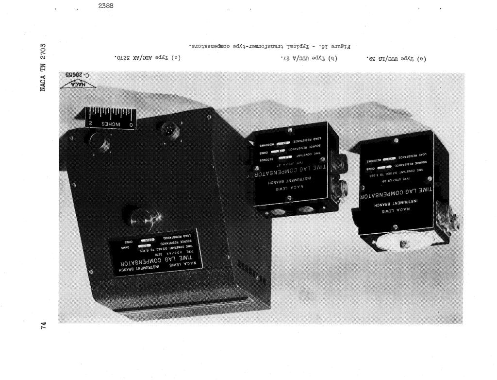
27 _G NACATN sgnal-to-nose rato _, and the frequency range to be covered (between cut-off ponts _a and a_o). Next t must be determned whether there exsts a sutable combnaton of crcut elements, preferably as represented by commercally avalable equpment, that wll approach the tentatve specfcatons. Fnally_ there s the practcal engneerng problem of reproducng the combnaton selected n approprate physcal form to meet requrements of ruggedness, freedom from mantenance, ablty to operate over a wde range of ambent temperature and of power supply voltage, long servce lfe, compactness, and low weght. Partcularly severe requrements may force the development of specal amplfers rather than allow the use of standard commercal equpment. f control, as well as measurement, s to be performed by the apparatus, the dynamc characterstcs of the controlelements and of the process to be controlled, as represented (f they are lnear) by ther respectve transfer functons, must also be consdered. n such stuatons_ t s concevable that t may be not only permssble for the temperature sgnal to be overcompensated, but also very desrable. Although the exact desgn of a complete compensatng system wll be determned by all the factors consdered n ths report, the followng general statements wll ad n the prelmnary decson on the most promsng lne of attack: () n general, the use of a transformer of hgh-qualty, multpleshelded, hum-buckng constructon wll be a valuable ad n mprovng the sgnal-to-nose rato. Unless the transformer s used also as a compensator, the mprovement n sgnal-to-nose rato s accomplshed at the expense of loss of d-c. response. (2) The attanable frequency response mprovement may be lmted by the product of detector sensblty and over-all gan of the system. (S) Whenan amplfer s used, the attanable frequency response may be lmted by the equvalent nput nose of the amplfer. (4) Transformer-type compensators usng typcal transformers such as those lsted n table wll not allow frequency response mprovement factors much greater than 50. (5) The potental performance of an RL or a transformer-type compensator may be serously restrcted f the element s called upon to feed a load resstance that s low comparedwth the output mpedance of the compensator. (6) The hghest tme constant that can be compensatedby a transformer-type compensator s determned by the product of prmary tme constant and turns rato and s of the order of several seconds.
28 2_ NACATN2703 (7) The hghest tme constant that can be compensatedby an RL compensator s of the order of a few tenths of a second; the frequency response mprovement attanable may be lmted by resonances or other nonlneartes of the nductor. (8) The hghest tme constant that can be compensatedfor and the frequency response mprovement attanable are not lmted by any ntrnsc qualtes of the RC compensator. C0 CC Fgure 16 shows three types of compensator constructed for use at the Lews laboratory. The followng dscusson wll ndcate the performance that may be expected from two representatve combnatons of apparatus that lend themselves, respectvely, to () the ndcaton of the alternatng component of a temperature sgnal (Example, usng an RC compensator); and (2) the ndcaton of the average value as well as the alternatng component of a temperature sgnal (Example 2, usng a transformer-type compensator). Both examples gven are characterzed by the fact that most of the componentsused are standard commercal ones. Both examples employ a transformer as a valuable ad n mprovng the sgnal-tonose rato. n the frst example, the transformer s used to match the low mpedance of the prmary element to the hgher mpedance of the amplfer, thus rasng the sgnal level; n the second example, the transformer s used as a compensator that does not greatly attenuate the sgnal as the RC or EL compensators do. Example. - For the assembly of apparatus represented by the block dagram of fgure 17(a), the over-all gan factor s a = Yl(j )Y2(j )Y3(j )Y (J )= (35) and the frequency response mprovement factor s F = F4, as gven n table. From equaton (21a) and the fact that E&,N<_Ez,N_3, the mnmum sgnal that can be detected s ether EA'N_4 < E2'N_4: (36a) EO, ran - G -- P.2G4 or E0,m n = _2_3 (36b)
29 NACA TN whchever of the two equatons yelds the greater value. Equaton (36a) represents the lmtaton mposed by nose; equaton (36b) represents the lmtaton mposed by detector sensblty. n equaton (36), the mportant quanttes are E0,m n sensblty of electrc equvalent of temperature sgnal E2_ N equvalent nput nose voltage of amplfer :::D So allowable sgnal-to-nose rato at detector G over-all gan factor % gan factor for combnaton of prmary element and compensator, as gven n table nput voltage sensblty of detector _2 transformer voltage gan, as gven by equaton (B5b) _3 amplfer voltage gan n regon of flat response constants For the group of apparatus shown n fgure 17(b), the followng apply: Prmary element (thermocouple) Tme constant, T, sec Electrc resstance, R, ohms Thermoelectrc power, Q, mcrovolts/ F Transformer Nomnal prmary mpedance (manufacturer's value), ohms Nomnal secondary mpedance (manufacturer's value), ohms... 50,000 Turns rato, N... _0 Low-frequency lmt for db drop n _2 (manufacturer's value), cps Low-frequency cut-off (based on manufacturer's low-frequency lmt), a_2,a, sec Hgh-frequency lmt for db change n _2 (manufacturer's value), cps... 20,000 D-c. resstance of prmary wndng, Rp_ ohms Maxmum unbalanced drect current for 1.5 db drop n _2 (manufacturer's value), mllamp... 5
30 26 NACA TN 2703 Compensator: RC type, tme constant T_ Amplfer nput mpedance, R3,2, ohms Output mpedance, R3,3, ohms Voltage gan n regon of flat response, _ Low-frequency lmt for 2 percent drop n _3 (manufacturer's value), cps... 0 Low-frequency cut-off (based on manufacturer's low-frequency lmt), _3,a, sec Hgh-frequency lmt for 2 percent change n _3 (manufacturer's value), cps... 00,000 Hgh-frequency cut-off wth 0.02 mcrofarad shunt across output, for nose reducton (_5,b = 51,000), cps Nose level E2, N referred to nput when output s shunted by 0.02 mcrofarad condenser, mllvolts Detector (cathode-ray osclloscope) nput mpedance, R5, ohms Senstvty, $5, n. deflecton/mllvolt Sensblty, 85, mllvolt nput (The detector sensblty 55 s determned not only by osclloscope characterstcs, such as sharpness of focus and senstvty, but also by the method of readng the deflectons. The stated sensblty s based on the fact that the osclloscope pattern wll be photographed and read to the equvalent of 0.02 n. deflecton on the osclloscope screen.) n ths tabulaton of apparatus, all components have been specfed except the components R, RC, and C of the compensator. For the desgn condton, T 1 = TA = 0.1 second and for a sgnal-to-nose rato _& = 3, table X lsts the sensbltes E0,m n and T0,mn(=E0,mn/Q), the senstvty S, and the upper frequency lmt f_,b for varous combnatons of R, RC, and C. The method used to compute the data n table X was (a) to assume varous values of GA and to nsert these values nto equaton (36) for computaton of the sensbltes; (b) to assume varous combnatons of R C and C, such that RcC = 0.1 second and then, usng the same values of G_ as n step (a), to compute R and then FA from table ; and (c) to compute
31 NACATN _A_b F_ (37) s = sso 2 3Q (3s) As shown n table X_ the amplfer nose, rather than the detector sensblty, lmts the mnmum sgnal whch can be detected. h_ C_ GO GO Usng the values of S = 1 nch per lo0 F, R C = 100 megohms, C = O.001 mcrofarad, R = lls,000 ohms_ and fa_b = 1_30 cycles per second, a mnmum sgnal of 90 F can be detected over a frequency range of about lo to lao0 cycles per second. Fgure 17(c) shows the computed frequency response curves based upon manufacturer's values for the transformer and amplfer constants and the computed effect of varatons n the thermocouple tme constant T 1. Expermental data ponts taken to check the computaton are also shown n fgure 17(c). The expermental ponts show that the manufacturer's statements of lowfrequency cut-off ponts were conservatve. The expermental data were obtaned by usng the analog crcut of fgure 17(d) to smulate the thermocouple. Snce the resstances of both the prmary element and the transformer prmary wndng are low ( and 0.8 ohm, respectvely)_ the net d-c. open-crcut output emf n the thermocouple crcut must be lmted to 8.5mllvolts to avod exceedng the transformer prmary saturaton current. Therefore, for temperature dfferences exceedng 380 F_ a buckng crcut of the type shown n fgure 17(e) would have to be used to suppress the average values of emf. The suppresson of excessve drect current through the transformer prmary could also be accomplshed by use of the crcut of fgure 17(f). The crcut of fgure 17(f) s usable only at hgher frequences where the hghest avalable sze of capactor can provde an mpedance that s low compared wth the transformer prmary mpedance. The crcuts of fgures 17(e) and 17(f) would be equally applcable f the prmary element were a temperature-senstve resstor 3 such as a straght length of wre wth current and potental leads. The nserton of a 1-ohm resstance n seres wth the prmary element would also serve to lmt the transformer prmary current at the expense of a loss n gan and a moderate ncrease n the lower cut-off frequency. Example 2. - For the assembly of apparatus represented by the block dagram of fgure 18(a), the tme constant, frequency response mprovement factor, and over-all gan factor are gven by equaton (28).
32 28 NACATN2703 Snce nose due to humpckup can be madeneglgble by careful sheldng and use of a hgh-qualty multple-shelded transformer, the mnmumdetectable sgnal wll be determned by the detector sensblty. For the group of apparatus shown n fgure 18(b), the followng constants apply: Prmary element (thermocouple) co co oa Tme constant, T, sec Electrc resstance_ R, ohms Thermoelectrc power, Q, mcrovolts/ F Compensator(transformer type) Nomnal prmary mpedance (manufacturer's value), ohms Nomnal secondary mpedance (manufacturer's value), ohms...00,000 D-c. resstance of prmary wndng, Rp, ohms... 6 D-c. resstance of secondary wndng, Rs, ohms Turns rato, N... A5 Added external prmary crcut resstance, Rp', ohms Tme constant, TA, sec Detector (d-c. amplfer and drect-wrtng recorder combnaton) nput mpedance, R5, ohms... 9X08 Senstvty, $5, mllvolts/mm deflecton Cut-off frequency, cps Sensblty, 65, mllvolts (correspondng to 0.5 deflecton)... O.5 The crcut requred to provde reference-juncton compensaton for the thermocouple s shown n fgure 18(c) (reference 9). f the prmary element were a temperature-senstve resstor, for example a straght length of wre wth current and potental leads, a crcut such as shown n fgure 18(d) could be used. Ths crcut, based on the multple-brdge crcut analyss of reference 0, s desgned to use a 0.02-ohm thermometer element (for example, a n. dameter platnum wre, 0.25 n. long) to provde the samevalues of R and Q as the thermocouple, and to lmt to less than 2 percent the errors caused by changes n thermometer-element lead resstances as hgh as ohm.
33 NACA TN c,o co co Fgure 18(e) ndcates the computed frequency response characterstcs for operaton both at the desgn pont (T = T) and at offdesgnponts. At the desgn pont, the upper frequency lmt s 7 cycles per second (_b = _5) and s determned by the value T/F = T/(N+ ) rather than by the cut-off frequency of the recorder. The expermentally determned responses to a step change and to an nput of arbtrary shape are shown n fgures 18(f) and 18(g), respectvely, for the same ratos T_TA as covered n fgure S(e). The analog crcut of fgure 17(d) was used to smulate the thermocouple. Thus, the orgnal 1.0-second tme constant of the prmary element s reduced by a factor of _6 to a value of approxmately 0.02 second. Lews Flght Propulson Laboratory Natonal Advsory Commttee for Aeronautcs Cleveland, Oho, January _, 1952
34 30 NACATN 2703 APPENDX A SYMBOLS The followng symbols are used n ths report: Ado attenuaton at zero frequency coeffcent of term n Fourer expanson of voltage sgnal representatve of temperature co co c_ C capactance C constant E rms value of voltage ampltude of voltage sne wave e nstantaneous value of _oltage F frequency response mprovement factor f frequency G gan factor g transconductance, output current per unt nput emf nstantaneous value of current J L self-nductance M mutual nductance N transformer turns rato n number of term n Fourer expanson P symbolc operator d/dr Q emf per unt temperature Change (= thermoelectrc power, for a thermocouple) R resstance
35 5G NACA TN r resstance rato (Rc+R)/R or (RL R)/R L S T senstvty, detector "deflecton per unt nput temperature snusodal ampltude of mpressed temperature varaton co co snusodal ampltude of prmary element temperature ndcaton t tme t* tme lag xc reactance of capactor Y(p) transfer functon Y(j ) output-nput snusodal voltage rato for a system havng a transfer functon Y(p) constant n expresson for F of transformer-type compensator feedback factor _dc d-c. feedback factor Y,Y2 constants n expresson for F of transformer-type compensator 8 sensblty (mnmum detectable sgnal) base of natural logarthms a phase lag angle of mpressed sne wave voltagegan sgnal-to-nose rato T tme constant phase lag angle angular frequency
36 32 NACATN 2703 Subscrpts: a low-frequency cut-off b N hgh-frequency nose cut-off _o co co P transformer prmary R reference temperature S transformer secondary load source 0 temperature beng measured 1 prmary element 2 transformer-preamplfer 3 amplfer compensator 5 detector 3A amplfer-compensator combnaton
37 NACA TN APPENDX B TRANSFER FUNCTON OF TRANSFOEMER ) D The transfer functon of a transformer wll be derved for those condtons that are pertnent to ts applcatons as a preamplfer and as a Compensator_ as treated n ths report. t s then possble to neglect the hysteress and eddy current losses and the capactances that ordnarly become mportant at hgher power levels and hgher frequences. The elements that prmarly enter,nto transformer performance as pertnent to ths report are shown n fgure 14(a)_ whch shows a transformer connected to a source resstance R a and a load resstance R k. The followng dfferental equatons hold: e = (Rl+Rp+LlP) + Mp 2 (B1) and o = (Rs+R_+L2p)2 +Mp (B2) The tr_sfer functon Y2(p) of the transformer wll be defned as the rato of the voltage across the load resstance to the open-crcut emf of the source. The defnton of Y2(p) thus ncludes the effects of the potental drops due to current flow through the source and through the transformer secondary. The followng transfer functon s obtaned from the smultaneous soluton'of equatons (B1) and (B2): e2 Y2(p): --: el MRAp (Rs+R_)(R+_)+[(Rs+R_ L+(Rl+_)L2]P+(LL2-_2)P2 (B3a) where e 2 = 2R k Equaton (B3a) yelds the frequency response functon Y2(j_) = Ja_Rk (Rs+R h) (R+Rp)+J_o[(Rs+Rk)L+(R+Rp)L2] -o_2(ll2-m2) (B4)
38 34 NACATN 2703 t s suffcent for the present analyss to assume M2 = LL 2 and N2 = L2/L 1. Then equaton (B3a) becomes (1/_2,a)P Y P) : _2 l+(/_2,a) p (B3D) where 1 L1 ( _,a - R7% +_2R_-_/ (BSa) co co _O oa N _2 = (B_) R s Rl+_ 1 + _ + N 2 Rk The value of _Y2(jo_)_ n the regon of flat frequency response s _2 and wll be termed the "gan" of the transformer. The angular frequency _2,a s the pont at whch Y2 (j_)l = _2/_ and wll be termed the "low-frequency cut-off" of the transformer. f R k >> Rs, equaton (BSb) becomes N (B6) Thus_ f R k >> Rs, the voltage gan s approxmately equal to N/2 RX/(Rl+ %) : N2,an_thevoltagegan_pproaches_ as R_(Rl+%) becomes much larger than N 2. f
39 NACA TN APPENDX C TRANSFER FUNCTON OF TRANSFORMER-TYPE COMPENSATOR ['o co co When the transformer s connected to a source of resstance R and a load of resstance R k as shown n fgure 14(b), the followng dfferental equatons hold: = p+ 2 (el) e : Rl + (Rp+Rp')p + LlP p - Mp 2 (c2) e = Rl + Rs 2 + Rk 2 + L2P 2 - Mpp (C5) From the smultaneous soluton of these equatons_ the followng transfer functon s obtaned: e 2 Y34(P)= _ = G54( + T4p) 1 + (T4/Fz4)p + ]_5p2 (C4a) where e 2 = 2R h (c4b) T L+M 4 Rp+Rp' + + R_j (c4c) (C4d) (ml)(_+) F34 = +.FN+_F2N 2 (C4e) R Rs+R A - Rp+Rp' R+Rs+R h (c4f)
40 $6 NACA TN 2703 %_ = _R1 R+Rs+RA (C4g) R+%+%' Y2 = R+Rs+R A Lf'2-M2 Y3 = _RxG34 (c4_) (c4) ro (D (D Equaton (C4a) can be expressed n terms of frequency as t s suffcent for the present analyss to assume M 2 = LL 2 and N 2 = LJL. Then equatons (C4a) and (C5) become l+t4p Y54(P) " G34 +(T4/Fz4)p (C6a) +j_t 4 Y34(j_) " G34 +J_T4/F34 (c7) f the source and load resstances are assumed to be zero and nfnte, respectvely, the value of T A s unchanged whle the values of G and F become The transfer functon then becomes %4 = (csa) F34= N + 1 (CSb) z34(p)= 1 + T4p T4 (C6b) 1 + _-_yp n the case of the transformer-type compensator that uses two prmary elements, as shown n fgure 14(c), the transfer functon s also gven by equaton (C6a), but there are slght changes n the values of T4, G34, and F34:
41 NACA TN L+M L = Rl+_+_' (C9a) R_ G54 = R+Rs+RZ (C9b) _o Go CO r_ : _+ _2(R+_+Rp,) (c9c) R+Rs+R _ n the dealzed case R = 0 and R k = _, equatons (C9a), (Cgb), and (C9c) become, respectvely, L+M % --Rp+Rp' (ClOa) G34 = F34 = N + (ClOb) (ClOc) and the transfer functon remans as gven by equaton (C6b). REFERENCES. Dryden, H. L., and Kuethe, A. M.: The Measurement of Fluctuatons of Ar Speed by the Hot-Wre Anemometer. NACA Rep. 520, Zegler, M.: The Constructon of a Hot Wre Anemometer wth Lnear Scale and Neglgble Lag. Verhandelngen d. Konnkljke Akademe v. Wetenschappen (Amsterdam), vol. XV, no., Kovasznay, Laszlo: Calbraton and Measurement nturbulence Research by the Hot-Wre Method. NACATM 1150, Scadron, Marvn D., and Warshawsky, sdore: Expermental Determnaton of Tme Constants and Nusselt Numbers for Bare-Wre Thermocouples n Hgh-Velocty Ar Streams and Analytc Approxmaton of Conducton and Radaton Errors. NACA TN 2599, Bush, Vannevar: Operatonal Crcut Analyss. John Wley & Sons, nc., 1937.
42 58 NACATN Carson, John R.: Electrc Crcut Theory and Operatonal Calculus. McGraw-Hll Book Co., nc., James, Hubert M., Nchols, Nathanel B., and Phllps, Ralph S.: Theory of Servomechansms. McGraw-Hll Book Co._ Terman, Frederck Emmons: Rado Engneerng. McGraw-Hll Book Co., nc., Eckman_Donald P.: ndustral nstrumentaton. John Wley & Sons, nc., co co 0. Warshawsky,sdore: A Multple Brdge for Elmnaton of Contact- Resstance Errors n Resstance Stran-Gage Measurements. NACA TN 1031, 1946.
43 6G NACA TN co co 0,3 TABLE - EFFECT OF LOADNG ON RC AND RL COMPENSATORS Compensator Rg=O R_=O General case R_ = Value of /G 4 RC R C _+ R R C + Rc+R _+1 R g RC.+ R_ + RL R _+ RL R + R+Rc_ RL + R+Rg L+R_,/ +1 Value of F 4 RC R C + R C R+Rc_ +1 R c RR_ + Rg R+R k +1 RL R+ RL _+ R+Rg RL +1 h(r+rg) +RX -+1 RL RL
44 40 NACA TN 2703 TABLE - MNMUM AMPLTUDE OF TEMPERATURE VARATON THAT CAN BE MEASURED BECAUSE OF NOSE LMTATON AT SGNAL- T0-NOSE RATO _4 EQUAL TO 3 09 O0 Frequency response mprovement factor F Nose E2,N (mcrovolts) Transformer gan W2 Sgnal sensblty EO,mn (mcrovolts) T0,mn for chromelalumel thermocouple 0 l l0 5O O l l O 1, ,000 l ,000 l0 5O 1, , , , O 0,000 45O 0,000 l _ ,000 l0 5O 0,000 45O
45 NACA TN 2703 _ TABLE CHARACTERSTCS OF TRANSFORMERS USED N REPRESENTATVE TRANSFORMER-TYPE COMPENSATORS co co Compensator type UTC/A 27 UTC/LS 39 ADC/AX 3270 Nomnal a prmary mpedance, ohms 5O 5O 1 Prmary nductance, L, henres D-c. resstance of prmary, Rp, ohms Nomnal a secondary mpedance, ohms 00_000 00, D-c. resstance of secondary_ Rs, ohms ll0 Turns rato_ N Nomnal b low-frequency cut-off pont, cps Nomnal b hgh-frequency cut-off, cps 20,000 20,000 2O We ght, b amanufacturer's stated value. bmanufacturer's stated value for 2 decbels change n gan.
46 42 NACATN 2705 O o 0 H C O m 0_ 0 _ 0 DO Oq CO O0 o _0 N o 0 0 _ b- LO 1,0 M _ O m co _ H to _0 O_llOl_looQ _ O _H o ! H M _ O b 0 o GO0,_ o _,a _ o o _ o_ ooo LO O _0_ 0_ O H _ _ H
47 2388 _9 TABLE V - EFFECT OF CONNECTNG TRANSFORMER-TYPE COMPENSATOR WTH SNGLE PRMARY ELEMENT TO DO PRMARY ELEMENT RESSTANCE R 1 AND TO LOAD RESSTANCE R k - Contnued (b) Type _TC/LS 59 R 1 (ohm) T4, see l& O.1 Rp', ohms F54 G54 g34 F54 GZ& g54 FS& GS& g54 F34 G54 g54 F54 G54 g54 FS& G54 gs& (mcromhos) (mcromhos) (mcromhos) (mcromhos) mcromhos) (meromhos l0 3 lo A o & & = & A1.95.& ! AO ) & ) & lo Z20 Z20 llo g_ O_
48 TABLE V - EFFECT OF CONNECTNG _RANSFORMER-TYPE COMPENSATOR WTH SNGLE PRMARY ELEMENT TO PRMARY ELEMENT RESSTANCE R 1 AND TO LOAD RESSTANCE R_ - Concluded ( ) Type AOC/AX 5270 Rk (megohms) R ohms) T4_ l sec Rp', ohms l0 F54 G54 g54 (mcromhos ! O1 o F54 G64 g54 mcromhos F54 G g54 mcromhos F54 G54 g54 mcromhos F54 G54 g54 mcromhos F54 G54 g54 mlcromhos ! lo O O0 1.O O l.& l O l& O , lo O o DO ",.4 O Oq 98_Z
49 L_ E-_ H _o 0 -H O O O LO O C_ E_ 1 r-t F-_ m r_ E- o o S S o - o_ o_ o_ e o - _o o o o_ F_ m o _ H E--t O E_ H CQ E_ o _ CO r...) o_ E-_ r..) _ O O O O O H o o O D-- O3 O E_ o r-,-t o o -4 O O O 2588
50 g_ o_ TABLE V - EFFECT OF CONNECTNG TRANSFORMER-TYPE COMPENSATOR WTH TWO PRMARY ELEMENTS TO PRMARY ELEMENT RESSTANCE R AND LOAD RESSTANCE R k - Contnued (b) Type UTC_ 39 Rk (megohms) R (ohms) T4; see G Rp'F34 F34 F34 F34 F34 F O 40 L.O 4O gsa,(mcromhos) A L14 6 6& _3 0 oq
51 238s TABLE V - EFFECT OF CONNECTNG TRANSF0_-TYPE COMPENSATOR WTH TWO PRMARY ELEMENTS TO PRMARY ELEMENT RESSTANCE R AND CO ,1 LOAD RESSTANCE R_- Concluded (o) my e ADC/AX3270 ' R _, R 1 T43 sec G34 g34 (megohms) (ohms) (mcromhos) Rp' F34 Rp' F54 Rp' F34 RO' F34 Rp' F34 Rp' F L c l O. 8 c 89O
52 00 PRMARY ELEMENTS AMPLFERS COMPENSATORS Component Thermocouple Resstance the_ometer D-c., no P-c., hghlow- or.frequency hghfrequency cut-off cut-offs Negatve feed- A-c., low- back, wlth tomfrequency pensatng netcut-off work _type RL type Dfferentlatlng R type 4c Trans foyer- Trans foyertype, sngle type, double element element RD+Rp Desgn vl constants Q = e1 T-T R T 1 Eo- Q(_o-TR 2,a _2,b N _2 _3 _5 _3,b _3 _3,a _3 _dc F34-1/G54-1-8dc_ 3 _4 " RcC (Rc/N)+ r - F4 - r G 4 - /r (a) _4 " L/KL _4' " RC F4 - r O 4 - /r (a) (a) L1 L l F34 - N+ F54. N+ G34 = G34 - (_) {a) Transfer 1 Y lp 1 (/_2,a)P Yg-_2[_ (1/_2,_N ]_+(1/_2,_)N] Y5 = _3 Y3 " a3(l_3,a)p +T4P z + _ F3 g +_4P 1+'_ 4P +T4p "-- Yg4 _4p Y34 1+ [_- + _4p N+ response _5,b (_) (a) (a) (a) _g,a W2, b _S,a F5_... /T l.o+---_, e _/T 4 r/ < _l / ( N+ )/v4 N+lr?/;4/gK- l.o F-+- _d--t-t "D_ we, a e3, a /T1 1/74 1/'t 4 0 /T 4 range j!los ' o /!1 frequency range eg,b _3, b FS4/T4 r/74 r/74 /_ 4 ' (N+)/74 (a) (a) (a] (a) (N+)/_& (al afor condtons of neglgble source resstance and load admttance. CO O Oq
53 2588 TABLE V - SUMMARY OF COMPENSATNG SYSTEMS bd -._ 0 04 [For condton T4 = _] System Prmary element and RC or RL compensator Prmary element and Double prmary ele- Prmary element, RC Prmary element, Prmary element, transformer-type ment and trans- or RL type compen- transformer, RC transformer, EC or or compensator former-type compen- sator, and d-c. RL type compensator, RL type compen- Prmary element and negatve feedback amplfer sator amplfer and amplfer wlth sator, and ampl- wlth compensatng low-frequency cut- fler wgh low- network n feed- off frequency cutoff (normal order) back loop (nverted order) Typcal components [--. c==,,v.- Transfer functon (Rl=O,RX=_) Frequency response system of 1 1 Y4Y = r _4 l+(_p (a) % 1/% r/_4 1 d d G=/rl Ys4Y T4p + (a) /T 4 (N+l 1/_ 4 fg= l 1 t Y34Y =--,\ G = \ /T 4 + T4P y4ysyl = _sg4 4p. _(N+l)/_4 % l+_ G'_sG4 FJ_4 1 l/t4 P/_2a G=_2_sG 4 7/ l!f1/'! //-, X, P/_3a 1 Y34Y = _sg54_a +'_m r34 G:_sG4 FsJ_,,,1 1/T4 \ Low-frequency None None None None None cut-off ea Hlgh-frequency cut-off _b r/t (a) (N+l)/_ 4 (a) (N+)/T4 (a) F4/" 4 F4/T4 F54/T4 Mlnmum slgnal lnput for 0 < E2,N/G 4 ge2,n/s2g4 E2,N/_2G4 E2,N/G34 s4=l; Eo,m n afor condton of neglgble prmary element resstance and load admttance..o
54 50 NACA TN 2703 TABLEV- EFFECTOFAMBENTEMPERATURE OND-C.OUTPUT OF SF0_-_Z C0_SA_0R (a) TypeUTC/A27 T 4 R (ohms) Percentage error for 00 F temperature change co col t,o o (b)_e UTC/_S 59 T4 R (ohms) Percentage error for 00 F temperature change R1 (o_) (c) Type ADC/AX 3270 T{ 3o o 3 l o.3 Percentage error for 00 F temperature change
55 ,-4 to dnooot_xaq% sm-a_-l_mom_d _ 009_ _ OL8 0C 0 OA9 _'0 O00cS oag O00C 019 OOCT 6 OO8 08_ O00:A_ 09_ 000c_ 0 00 c /9 O00 OASC8 O@ O00(og LZT O00(T 6"0 OZ O L_ OOLC_ "0 L'9 0 (s o) qc_ (su_qo) (sdo) (_o) (s%loxoao_) P/_ O0"O = O smqo_sm OO = 0_ P/_O'O = D smqo_em O = DE P/_T'O = D mqo_ = D_ (X%TAT%sues _o%o_$ep o% 8up) X%qsuss (_STOU XSTTdUZe o% enp) X%TTqTsue S _ :_o o_%_a gs_ou-o%-_u_s {o_s T'O _ %u_%suooemt._ 3 _O&VS_SzU40D XO D CL_V _DK :_ XO S_O_V OD SAOhqfA KO_ (q)a _NLOX XO _SAS ON_VS_O0 _0 ZDkfVhq_O_T_x - X _KV_ 0 oa 88 8
56 52 NACA TN 2703 / J J / /f ba C]C) CO T/ATo : / T 2T 3T 4T 1 5"rz 6 h (a) Tme hstory of response to step change. Gas temperature, T O _element temperature_ T 1 JJ J f t a Tme lag J E_ Tme _ t (b) Tme hstory of response to snnsodal varaton. Fgure. - Response of prmary element.
57 NACA TN Z 1! \ JLl llt!!!! : : co co _O o_,o o_ 4_.1 llj\ : :::, \ E ll \,! : ::::: ' l :::,,: ll 4a.q K4.01! lll!!!! lll [ll lll... "-,., lllll _. 1 "_,... ttt ", (c) Frequency-response relaton; ampltude rato. 00 T1 l _o 8o _ : / ".8_" _ r- t_o c_ 6o AO lll_ :/2\ ll _ ' " _3 r_ ffl 2O 0 O/T [ ll _/ /.1/'_ 1 o/_ 1 l] fll L llll 100/" Jl.2_" o looo/_-1 Angular frequency, (d) Frequency-response relaton; phase and tme lag. Fgure 1. - Concluded. Response of prmary element
58 54 NACA TN 2703 C o + T_p R C Y4(P) = r + (T4/r)p T 4 = RcC CO CO r : Rc/R + O O (a) RC type. R R L _ + T4p YA(P) r + (T4/r)p L T 4 = L/R L r = R/R L + O O O L L 2 = N2L Y34 (p) T 4 + T4p T4P N+ : (N+)L/ (c) Transformer type. Fgure 2. - Basc compensator networks and ther transfer functons
59 ,G NACA TN lo0 CO CO O 0,1 /r lt 4 r/_4 (d) Value of Y(J_o) as functon of frequency for RC and RL compensators. (Log-log scale.) N+ 1.O J /T 4 (N+)/T 4 Angular frequency, (e) Value of Y(J_) as functon of frequency for transformer-type compensator. (Log-log scale.) Fgure 2. - Concluded. Basc compensator networks and ther transfer functons.
60 56 NACATN 2703 e0 Y _- el [ Y2 "l e2 -] Y5 l e5= J e5 = Y3e2 = Y3Y2e = Y3Y2Ye 0 (a) Cascaded system. ; Y2,1 l _- $ [ 1 e1 e2 Y2_2 e2,2 e2 = e2,1 + e2,2 = (Y2,1 + Y2,2) el = Y2el (b) Addtve system. = TP ----e_+t-_.s -4 Y : Y4 : _0 e0 e 2 w Y _- +T p e2/e0 = Y1 + YY4 = (c) Example of combned cascaded and addtve systems. Fgure 3. - Transfer functon composton for lnear systems.
61 NACATN Network Performanceparameters 0o Gas temperature l Prmary element _ L'?_, 'l T1 Q eo = Q(To - TR) tme constant emf per unt temperature change e : Q(T 1 - TR) N turns rato Transformer _2,a _2,b 10w-frequency cut-off pont hgh-frequency cut-off pont _3 amplfcaton factor Amplfer _ 3,a _O3,b E2,N low-_requency cut-off pont hgh-frequency cut-off pont equvalent rms nput nose Compensator T4 F 4 G4 tme constant response mprovement factor gan factor Detector 55 sens b lty S5 senstvty Fgure 4. - Typcal block dagram for defnton of termnology.
62 r-_ 111 r! (uncompensated) O] Co m m m m m \ 0 g _.0_ m m j m u m m % m \ 001.1/T 4 Angular frequency, (a) Frequency-response relaton; ampltude rato. Fgure 5. - Response of prmary element wth RC or RL compensatot. Prmary element resstance and compensator load admttance assumed neglgble. T 4 =T 1. _S co o c_... g_ez...
63 T4/r DO _q O _0 J 8O 6O 4O / X,\ / / \.6T4/r 20 0 tan - (_T4_ / --4.1/(%/;) \.01/(T4/r ) 1/(T 4/r ) 0/( T4/r ) 00/( 1-4/r ).2T4/r 0 lo00/(t4/r) Angular frequency_ (b) Frequency-response relaton; phase lag and tme lag. Fgure 5. - Contnued. Response of prmary element wth RC or RL compensator. mary element resstance and compensator load admttance assumed neglgble. Pr- T 4 = T_ O7 (o
64 y p._ E-_ ao_'_%%ymp'e p'_o _o'$_9uaclmoo pu'_ aou'eq.sr.sa.z q.uautata,'euzy.zct ",_o%_e, uac.moo "_,zo 0_ -qq.t..'_ %_auzat.a,'_mt..d o asuoclsae "papnauoo - "g aan_l:_ a_u_qo da%_ o% asuod:se,z jo _o%ssq emt,r, (o) j/ O 0 c+ v o //- E'O o% _-J l Oq! c+ _m.-.c+ v (pa%_suedmo oun)_ / %Tu-a o% / 0
65 NACA TN CO CO Oa (a) RC compensator. e5 Ra R w TR h L e (b) RL compensator. Fgure 6. - RC and RL compensators connected to source and load.
66 62 NACATN 2703 Network Performance parameters O_ T tme constant Prmary element Q emf per unt temperature change _5 amplfcaton factor Amplfer _es_ R5,3 _5,a low-frequency cut-off pont _3,b hgh-frequency cut-off pont E2, N equvalent rms nput nose d_ T 4 tme constant Compensator F 4 response mprovement factor q) () GA gan factor m _ R8 _ m Detector e_ 8 5 sensblty S 5 senstvty Fgure 7. - RC or RL compensatng system usng amplfer.
67 9G NACA TN _3G4 GO CO o v v _3 _2 r-4 _sg 4 l lltl!!!_l,...,,,, r_._... \ llle lllll E fll rll lll... 1_ L L _ ll<'-. 1ple : : : :: \ "_ l[ \ '. _ U lllll J[rll r rljr %f_ 01 $3G4... lll,\\ (a) Frequency-response relaton; ampltude rato 2OO 180,,,r,-_.... llt 11Llt lll _ '_'" kl No hlgh-frequency cut-off _3,b " OF4/T4 2_F 4 o 8 _4/F4 160 ' '1[ J l N_ M 140 llll, _,_,,\... \ \._/ /... / / y / /. 6 T_/F 4 1o4_4/F4...-_ \ / oo,,, _.lll... "S,.. _1,!!!!!z...,, \ t'l /! /111[ lo_j_4.8_jf4 t E_ lll! _ \_,, A,, o 6 TUF A "k_...,j // " _' gl 4O ::: ll11 4 _4/F4 2o 2T4/F4 0'' oo_F_4.Ol_J_4 100FU_ 4 Angular frequency, (b) Frequency-response relaton; phase and tme lago Fgure 80 - Response of RC or RL compensatng system usng amplfer wth hgh-frequency cut-offo T4 = T 1.
68 o_.o_sg _ o 0D o" -r4 4_ 8_sG _ 6_5G 4 / / ////'/ / / s / / / / S / s / s / v / No hgh-frequency cut-off _5_b = OF4/T4 _5_b = F4/T4 4_ 4_3a4 /11,/, / /, 2_5G 4 /,, / / 0 T4/F 4 Tme_ t (c) Tme hstory of response to step change. Fgure 8. - Concluded. Response of RC or RL compensatng system usng amplfer wth hgh-frequency cut'off. T 4 = T. [_ c_ L_ 88_
69 NACA TN co co g_ 3 g _3 G4!_3G _ / ---- [ /j / ll;; _J...,,,_-.,,, 12T....,_' ] _ / r 1_ J._,... JJJ _ \ \ L _ :... lllll,! :_:::!!!\...\.Olb3G, / /.P / +lll E Ell 1_ ll,, \ (a) Frequency-response relaton; ampltude rato. 00 No low-frequency cut-off / tll.1f_'+_ 100F4/T _ Angular frequency, (b) Frequency-response relatons; phase lag angle Fgure 9o - Response of RC or RL compensatng system usng amplfer wth low-frequency cut-offo T 4 = T1.
70 66 NACA TN s3ga f -- cut-off o % <_ g 8 _3Gzt 6 _3G4 03 CO _0 c_ o AP,3Gzl.2 #sg& 0 Tme, t 8T /F_ OT4/F A (c) Tme hstory of response to step change..os3g & O(T4/F4) O H 8 _5G_! 8(T_/%) _0 _D > _o.6_3g 4 -- // (D llrll / L _(_/%) o o H c_ 2 SsG4 / / 2(_4/F 4) _D o,,,,, 0 1 o Rato of upper frequency lmt to lowfrequency cut-off, F_/(_,a) (d) Maxmum value reached and tme to reach maxmum value n response to step change. Fgure 9. - Concluded Response of RC or RL compensatng system usng amplfer wth low-frequency cut-off T& _ T.
71 NACA TN Network Performance parameters CO co oa Prmary element O O O_ el _R T Q tme constant emf per unt temperature change O 9 T A tme constant Compensator O ( F4 response mprovement factor G4 gan factor 2 _3 amplfcaton factor Amplfer 9 4' <'R5 _3,a low-frequency cut-off pont _5_b hgh-frequency cut-off pont,3 E2, N equvalent rms nput nose Detector 8 5 sensblty S 5 senstvty Fgure 0. - Compensatng system wth postlons of amplfer and compensator nterchanged.
72 68 NACATN 2705 Network Performanceparameters Prmary element T1 Q tme constant emf per unt temperature change Transformer N turns rato _2_a low-frequency cut-off pont _2_b hgh-frequency cut-off pont 2 _3 amplfcaton factor Amplfer _3ja low-frequency cut-off pont _3,b hgh-frequency cut-off pont _R_, 5 E23 N equvalent rms nput nose T4 tme constant Compensator F_ G4 response mprovement factor gan factor Detector 55 sensblty S 5. senstvty Fgure. - Compensatng system usng transformer as nose-free preamplfer.
73 NACA TN voutput transformer L co co 5o.qj o _l 6 j L_ mer Chopper A-c. amplfer Chopper Flter Prlmaryelement Chopper-type amplfer Compensator (a) Chopper-type amplfer. o o Y Y2 L Y4 (el+e 4) Prmary element Transformer Amplfer Compensator eo Prmary element (b) Addton of sgnal from second prmary element. Fgure Technques for mantanng d-c. response when transformer or a-c. amplfer s used.
74 70 NACA TN 2705 e 1 v _3 e5& l Amplfer _dc Compensatng network, _(P) - +TAp Fgure Negatve feedback amplfer wth compensatng network n feedback loop; _dc_ fracton of output voltage e3a appearng across _ at zero frequency; T A, product of capactance C and parallel resstance of output and nput resstances of compensatng flter.
75 10G NACA TN _ 2 %) D D T M q-csl '2, _--_ R k e 2 Transformer (a) Basc transformer crcut. Elements shown dashed may be neglected for most compensator applcatons. The ron losses are represented by 22 R_.,---e _ %AA/V_ e ----O T M R s e, E_ +T4.P Y3 a +(TJF)p (b) One prmary element. 7 R], R_ el t_ J_,_J L2 Y5 = G l+_4p l+'(',4/f)_ [ (c) Two prmary elements. Fgure Transformer and _s use as compensator.
76 72 NACA TN 2705 T4:;T _3 CO CO \ 3 v 3 *rt.0_" / X, x X\ k,,", \ \ \ \ \ \.003 1/T_ 1/+_ lo/t_ L O0/T A Angular frequency, (a) Frequency-response relaton; ampltude rato. Fgure Effect of msmatch between prmary element and compensator tme constants; F4G _ assumed equal to.
77 NACA TN O2 r lo0 O1 5f -f <_.2 o.1.ta f f T4: 4:T4: 6TA Tme 3 t (b) Tme hstory of response to step change. Fgure Concluded. Effect of msmatch between prmary element and compensator tme constants; F_G_ assumed equal to 1.
78 887_ 0
79 NACA TN Network Performance parameters Gas temperature co co _D r--eo _ Prmary element (thermocouple) '' 6 o T tme constant Q emf per unt temperature change Transformer N turns rato _2,a low-frequency cut-off pont _2_b hgh-frequency cut-off pont _5 amplfcaton factor Amplfer _5_a low-frequency cut-off pont es_b hgh-frequency cut-off pont e 3 E2_ N equvalent rms nput nose ) T 4 tme constant Compensator F4 response mprovement factor G gan factor Detector _v_ 55 sensblty (cathode-ray osclloscope) 55 senstvty (a) Block dagram. Fgure Compensated system for measurement of alternatng component of temperature.

80 ... _ :... _:_: ::x : k _ s :... _:: <_ _ : :<:<:: ::: : x:::::::::::::::: :::::::::2: :<::::::::: ::::::x2::::::: :::::::2::::::::::::::::::::x::::::::::::::::::::::::::::::::::::::::::::::: :::::::::::::::::!:::::::::_:_::::::::::_:!:::_:::_:_: O_ Fgure Contnued. (b) Representatve arrangement of apparatus. Compensated system for measurement of alternatng component of temperature. co O C_
81 lo 0 o u_ Ol lo Angular frequency ; rad/sec 0_000 00_000 (c) Frequency response relaton; ampltude rato. Fgure Contnued. Compensated system for measurement of alternatng component of temperature ]
82 78 NACA TN 2705 eol.- TC R 1 _ el Co (d) Electrcal analog of thermocouple wth adjustable tme constant. el Y'(!o) = eo : G 1 l+tlp where T 1 = R0_+R0_2+R1 R0'(R0'z+R1) C and R 1 G = RO _+R0,2+R Fgure 17. Contnued. Compensated system for measurement of alternatng component of temperature.
83 G NACA TN co e0 _o oa O 0"---1 O &--J (e) Buckng crcut to reduce d-c. emf level. Rsh <<R_ C O (_ O (f) Capactance couplng crcut to block d-c. sgnal. X C = _-_ must be small compared wth R x. Fgure Concluded. Compensated system for measurement of alternatng component of temperature.
84 80 NACATN 27O3 Network Performance parameters Gas temperature --,??, _o O_ (D eo Prmary element (thermocouple) o 6 T tme constant Q emf per unt temperature change Compensator (transformer-type) T 4 tme constant F 4 response mprovement factor G4 gan factor Detector (drect coupled amplfer, recorder) e sensblty $5 senstvty (a) Block dagram. _(A_ Fgure Compensated system for measurement of average value as well as alternatng component of temperature.

85 (b) Representatve arrangement of apparatus. Fgure Contnued. Compensated system for measurement of average value as well as alternatng component of temperature. co
antenna antenna (4.139)
") .6.6 The Lmts of Usable Input Levels for LNAs The sgnal voltage level delvered to the nput of an LNA from the antenna may vary n a very wde nterval, from very weak sgnals comparable to the nose level,
.6.6 The Lmts of Usable Input Levels for LNAs The sgnal voltage level delvered to the nput of an LNA from the antenna may vary n a very wde nterval, from very weak sgnals comparable to the nose level,
Passive Filters. References: Barbow (pp ), Hayes & Horowitz (pp 32-60), Rizzoni (Chap. 6)
, Hayes & Horowitz (pp 32-60), Rizzoni (Chap. 6)") Passve Flters eferences: Barbow (pp 6575), Hayes & Horowtz (pp 360), zzon (Chap. 6) Frequencyselectve or flter crcuts pass to the output only those nput sgnals that are n a desred range of frequences (called
Passve Flters eferences: Barbow (pp 6575), Hayes & Horowtz (pp 360), zzon (Chap. 6) Frequencyselectve or flter crcuts pass to the output only those nput sgnals that are n a desred range of frequences (called
Sensors for Motion and Position Measurement
 Sensors for Moton and Poston Measurement Introducton An ntegrated manufacturng envronment conssts of 5 elements:- - Machne tools - Inspecton devces - Materal handlng devces - Packagng machnes - Area where
To: Professor Avitabile Date: February 4, 2003 From: Mechanical Student Subject: Experiment #1 Numerical Methods Using Excel
 To: Professor Avtable Date: February 4, 3 From: Mechancal Student Subject:.3 Experment # Numercal Methods Usng Excel Introducton Mcrosoft Excel s a spreadsheet program that can be used for data analyss,
TECHNICAL NOTE TERMINATION FOR POINT- TO-POINT SYSTEMS TN TERMINATON FOR POINT-TO-POINT SYSTEMS. Zo = L C. ω - angular frequency = 2πf
 TECHNICAL NOTE TERMINATION FOR POINT- TO-POINT SYSTEMS INTRODUCTION Because dgtal sgnal rates n computng systems are ncreasng at an astonshng rate, sgnal ntegrty ssues have become far more mportant to
MTBF PREDICTION REPORT
 MTBF PREDICTION REPORT PRODUCT NAME: BLE112-A-V2 Issued date: 01-23-2015 Rev:1.0 Copyrght@2015 Bluegga Technologes. All rghts reserved. 1 MTBF PREDICTION REPORT... 1 PRODUCT NAME: BLE112-A-V2... 1 1.0
Uncertainty in measurements of power and energy on power networks
 Uncertanty n measurements of power and energy on power networks E. Manov, N. Kolev Department of Measurement and Instrumentaton, Techncal Unversty Sofa, bul. Klment Ohrdsk No8, bl., 000 Sofa, Bulgara Tel./fax:
ECE 2133 Electronic Circuits. Dept. of Electrical and Computer Engineering International Islamic University Malaysia
 ECE 2133 Electronc Crcuts Dept. of Electrcal and Computer Engneerng Internatonal Islamc Unversty Malaysa Chapter 12 Feedback and Stablty Introducton to Feedback Introducton to Feedback 1-4 Harold Black,
Microelectronic Circuits
 Mcroelectronc Crcuts Slde 1 Introducton Suggested textbook: 1. Adel S. Sedra and Kenneth C. Smth, Mcroelectronc Crcuts Theory and Applcatons, Sxth edton Internatonal Verson, Oxford Unersty Press, 2013.
Triferential Subtraction in Strain Gage Signal Conditioning. Introduction
 Trferental Subtracton n Stran Gage Sgnal Condtonng Karl F. Anderson Vald Measurements 3751 W. Ave. J-14 Lancaster, CA 93536 (661) 722-8255 http://www.vm-usa.com Introducton The general form of NASA's Anderson
Shunt Active Filters (SAF)
") EN-TH05-/004 Martt Tuomanen (9) Shunt Actve Flters (SAF) Operaton prncple of a Shunt Actve Flter. Non-lnear loads lke Varable Speed Drves, Unnterrupted Power Supples and all knd of rectfers draw a non-snusodal
EN-TH05-/004 Martt Tuomanen (9) Shunt Actve Flters (SAF) Operaton prncple of a Shunt Actve Flter. Non-lnear loads lke Varable Speed Drves, Unnterrupted Power Supples and all knd of rectfers draw a non-snusodal
RC Filters TEP Related Topics Principle Equipment
 RC Flters TEP Related Topcs Hgh-pass, low-pass, Wen-Robnson brdge, parallel-t flters, dfferentatng network, ntegratng network, step response, square wave, transfer functon. Prncple Resstor-Capactor (RC)
29. Network Functions for Circuits Containing Op Amps
 9. Network Functons for Crcuts Contanng Op Amps Introducton Each of the crcuts n ths problem set contans at least one op amp. Also each crcut s represented by a gven network functon. These problems can
ECE315 / ECE515 Lecture 5 Date:
 Lecture 5 Date: 18.08.2016 Common Source Amplfer MOSFET Amplfer Dstorton Example 1 One Realstc CS Amplfer Crcut: C c1 : Couplng Capactor serves as perfect short crcut at all sgnal frequences whle blockng
POLYTECHNIC UNIVERSITY Electrical Engineering Department. EE SOPHOMORE LABORATORY Experiment 1 Laboratory Energy Sources
 POLYTECHNIC UNIERSITY Electrcal Engneerng Department EE SOPHOMORE LABORATORY Experment 1 Laboratory Energy Sources Modfed for Physcs 18, Brooklyn College I. Oerew of the Experment Ths experment has three
Calculation of the received voltage due to the radiation from multiple co-frequency sources
 Rec. ITU-R SM.1271-0 1 RECOMMENDATION ITU-R SM.1271-0 * EFFICIENT SPECTRUM UTILIZATION USING PROBABILISTIC METHODS Rec. ITU-R SM.1271 (1997) The ITU Radocommuncaton Assembly, consderng a) that communcatons
High Speed ADC Sampling Transients
 Hgh Speed ADC Samplng Transents Doug Stuetzle Hgh speed analog to dgtal converters (ADCs) are, at the analog sgnal nterface, track and hold devces. As such, they nclude samplng capactors and samplng swtches.
Figure 1. DC-DC Boost Converter
 EE46, Power Electroncs, DC-DC Boost Converter Verson Oct. 3, 11 Overvew Boost converters make t possble to effcently convert a DC voltage from a lower level to a hgher level. Theory of Operaton Relaton
Walsh Function Based Synthesis Method of PWM Pattern for Full-Bridge Inverter
 Walsh Functon Based Synthess Method of PWM Pattern for Full-Brdge Inverter Sej Kondo and Krt Choesa Nagaoka Unversty of Technology 63-, Kamtomoka-cho, Nagaoka 9-, JAPAN Fax: +8-58-7-95, Phone: +8-58-7-957
EE 508 Lecture 6. Degrees of Freedom The Approximation Problem
 EE 508 Lecture 6 Degrees of Freedom The Approxmaton Problem Revew from Last Tme Desgn Strategy Theorem: A crcut wth transfer functon T(s) can be obtaned from a crcut wth normalzed transfer functon T n
Network Theory. EC / EE / IN. for
 Network Theory for / / IN By www.thegateacademy.com Syllabus Syllabus for Networks Network Graphs: Matrces Assocated Wth Graphs: Incdence, Fundamental ut Set and Fundamental rcut Matrces. Soluton Methods:
Figure 1. DC-DC Boost Converter
 EE36L, Power Electroncs, DC-DC Boost Converter Verson Feb. 8, 9 Overvew Boost converters make t possble to effcently convert a DC voltage from a lower level to a hgher level. Theory of Operaton Relaton
Chapter 13. Filters Introduction Ideal Filter
 Chapter 3 Flters 3.0 Introducton Flter s the crcut that capable o passng sgnal rom nput to output that has requency wthn a speced band and attenuatng all others outsde the band. Ths s the property o selectvty.
Figure.1. Basic model of an impedance source converter JCHPS Special Issue 12: August Page 13
 A Hgh Gan DC - DC Converter wth Soft Swtchng and Power actor Correcton for Renewable Energy Applcaton T. Selvakumaran* and. Svachdambaranathan Department of EEE, Sathyabama Unversty, Chenna, Inda. *Correspondng
NATIONAL RADIO ASTRONOMY OBSERVATORY Green Bank, West Virginia SPECTRAL PROCESSOR MEMO NO. 25. MEMORANDUM February 13, 1985
 NATONAL RADO ASTRONOMY OBSERVATORY Green Bank, West Vrgna SPECTRAL PROCESSOR MEMO NO. 25 MEMORANDUM February 13, 1985 To: Spectral Processor Group From: R. Fsher Subj: Some Experments wth an nteger FFT
Development of a High Bandwidth, High Power Linear Amplifier for a Precision Fast Tool Servo System
 Development of a Hgh Bandwdth, Hgh Power near Amplfer for a Precson Fast Tool Servo System S. Rakuff 1, J. Cuttno 1, D. Schnstock 2 1 Dept. of Mechancal Engneerng, The Unversty of North Carolna at Charlotte,
Design of Shunt Active Filter for Harmonic Compensation in a 3 Phase 3 Wire Distribution Network
 Internatonal Journal of Research n Electrcal & Electroncs Engneerng olume 1, Issue 1, July-September, 2013, pp. 85-92, IASTER 2013 www.aster.com, Onlne: 2347-5439, Prnt: 2348-0025 Desgn of Shunt Actve
Digital Transmission
 Dgtal Transmsson Most modern communcaton systems are dgtal, meanng that the transmtted normaton sgnal carres bts and symbols rather than an analog sgnal. The eect o C/N rato ncrease or decrease on dgtal
Unit 1. Current and Voltage U 1 VOLTAGE AND CURRENT. Circuit Basics KVL, KCL, Ohm's Law LED Outputs Buttons/Switch Inputs. Current / Voltage Analogy
 ..2 nt Crcut Bascs KVL, KCL, Ohm's Law LED Outputs Buttons/Swtch Inputs VOLTAGE AND CRRENT..4 Current and Voltage Current / Voltage Analogy Charge s measured n unts of Coulombs Current Amount of charge
Strain Gauge Measuring Amplifier BA 660
 Stran Gauge Measurng Amplfer BA 660 Orgnal of the Manual BA660 / IP20 BA660 / IP66 Table of Contents 1. Safety precautons...2 1.1. Feld of applcaton...2 1.2. Installaton...2 1.3. Mantenance...2 2. Functon...2
Lecture 10: Bipolar Junction Transistor Construction. NPN Physical Operation.
 Whtes, EE 320 Lecture 10 Page 1 of 9 Lecture 10: Bpolar Juncton Transstor Constructon. NPN Physcal Operaton. For the remander of ths semester we wll be studyng transstors and transstor crcuts. The transstor
THE GENERATION OF 400 MW RF PULSES AT X-BAND USING RESONANT DELAY LINES *
 SLAC PUB 874 3/1999 THE GENERATION OF 4 MW RF PULSES AT X-BAND USING RESONANT DELAY LINES * Sam G. Tantaw, Arnold E. Vleks, and Rod J. Loewen Stanford Lnear Accelerator Center, Stanford Unversty P.O. Box
Harmonic Balance of Nonlinear RF Circuits
 MICROWAE AND RF DESIGN Harmonc Balance of Nonlnear RF Crcuts Presented by Mchael Steer Readng: Chapter 19, Secton 19. Index: HB Based on materal n Mcrowave and RF Desgn: A Systems Approach, nd Edton, by
Analysis, Design, and Simulation of a Novel Current Sensing Circuit
 Analyss, Desgn, and Smulaton of a Noel Current Sensng Crcut Louza Sellam Electrcal and Computer Engneerng Department US Naal Academy Annapols, Maryland, USA sellam@usna.edu obert W. Newcomb Electrcal and
MASTER TIMING AND TOF MODULE-
 MASTER TMNG AND TOF MODULE- G. Mazaher Stanford Lnear Accelerator Center, Stanford Unversty, Stanford, CA 9409 USA SLAC-PUB-66 November 99 (/E) Abstract n conjuncton wth the development of a Beam Sze Montor
AC-DC CONVERTER FIRING ERROR DETECTION
 BNL- 63319 UC-414 AGS/AD/96-3 INFORMAL AC-DC CONVERTER FIRING ERROR DETECTION O.L. Gould July 15, 1996 OF THIS DOCUMENT IS ALTERNATING GRADIENT SYNCHROTRON DEPARTMENT BROOKHAVEN NATIONAL LABORATORY ASSOCIATED
Control of Chaos in Positive Output Luo Converter by means of Time Delay Feedback
 Control of Chaos n Postve Output Luo Converter by means of Tme Delay Feedback Nagulapat nkran.ped@gmal.com Abstract Faster development n Dc to Dc converter technques are undergong very drastc changes due
A Comparison of Two Equivalent Real Formulations for Complex-Valued Linear Systems Part 2: Results
 AMERICAN JOURNAL OF UNDERGRADUATE RESEARCH VOL. 1 NO. () A Comparson of Two Equvalent Real Formulatons for Complex-Valued Lnear Systems Part : Results Abnta Munankarmy and Mchael A. Heroux Department of
Comparative Analysis of Reuse 1 and 3 in Cellular Network Based On SIR Distribution and Rate
 Comparatve Analyss of Reuse and 3 n ular Network Based On IR Dstrbuton and Rate Chandra Thapa M.Tech. II, DEC V College of Engneerng & Technology R.V.. Nagar, Chttoor-5727, A.P. Inda Emal: chandra2thapa@gmal.com
Voltage Quality Enhancement and Fault Current Limiting with Z-Source based Series Active Filter
 Research Journal of Appled Scences, Engneerng and echnology 3(): 246-252, 20 ISSN: 2040-7467 Maxwell Scentfc Organzaton, 20 Submtted: July 26, 20 Accepted: September 09, 20 Publshed: November 25, 20 oltage
PRACTICAL, COMPUTATION EFFICIENT HIGH-ORDER NEURAL NETWORK FOR ROTATION AND SHIFT INVARIANT PATTERN RECOGNITION. Evgeny Artyomov and Orly Yadid-Pecht
 68 Internatonal Journal "Informaton Theores & Applcatons" Vol.11 PRACTICAL, COMPUTATION EFFICIENT HIGH-ORDER NEURAL NETWORK FOR ROTATION AND SHIFT INVARIANT PATTERN RECOGNITION Evgeny Artyomov and Orly
ECEN 5014, Spring 2013 Special Topics: Active Microwave Circuits and MMICs Zoya Popovic, University of Colorado, Boulder
 ECEN 514, Sprng 13 Specal Topcs: Acte Mcrowae Crcuts and MMICs Zoya Popoc, Unersty of Colorado, Boulder LECTURE 4 BROADBAND AMPLIFIERS L4.1. INTRODUCTION The challenge n desgnng a broadband mcrowae amplfer
Section 5. Signal Conditioning and Data Analysis
 Secton 5 Sgnal Condtonng and Data Analyss 6/27/2017 Engneerng Measurements 5 1 Common Input Sgnals 6/27/2017 Engneerng Measurements 5 2 1 Analog vs. Dgtal Sgnals 6/27/2017 Engneerng Measurements 5 3 Current
Graph Method for Solving Switched Capacitors Circuits
 Recent Advances n rcuts, ystems, gnal and Telecommuncatons Graph Method for olvng wtched apactors rcuts BHUMIL BRTNÍ Department of lectroncs and Informatcs ollege of Polytechncs Jhlava Tolstého 6, 586
Biomedical Instrumentation
 Bomedcal Instrumentaton Amplers & Wnter 1393 Bonab Unersty Applcatons o Operatonal Ampler (In Bologcal s and Systems) The three major operatons done on bologcal sgnals usng OpAmp: 1) Amplcatons and Attenuatons
Optimization Frequency Design of Eddy Current Testing
 Optmzaton Frequency Desgn of Eddy Current Testng NAONG MUNGKUNG 1, KOMKIT CHOMSUWAN 1, NAONG PIMPU 2 AND TOSHIFUMI YUJI 3 1 Department of Electrcal Technology Educaton Kng Mongkut s Unversty of Technology
Control Chart. Control Chart - history. Process in control. Developed in 1920 s. By Dr. Walter A. Shewhart
 Control Chart - hstory Control Chart Developed n 920 s By Dr. Walter A. Shewhart 2 Process n control A phenomenon s sad to be controlled when, through the use of past experence, we can predct, at least
Introduction to Amplifiers
 Introducton to Amplfers Dad W. Graham West Vrgna Unersty Lane Department of Computer Scence and Electrcal Engneerng Dad W. Graham, 07 Small Wggles To Bg Wggles Amplfcaton s extremely mportant n electroncs
IEE Electronics Letters, vol 34, no 17, August 1998, pp ESTIMATING STARTING POINT OF CONDUCTION OF CMOS GATES
 IEE Electroncs Letters, vol 34, no 17, August 1998, pp. 1622-1624. ESTIMATING STARTING POINT OF CONDUCTION OF CMOS GATES A. Chatzgeorgou, S. Nkolads 1 and I. Tsoukalas Computer Scence Department, 1 Department
Dual Functional Z-Source Based Dynamic Voltage Restorer to Voltage Quality Improvement and Fault Current Limiting
 Australan Journal of Basc and Appled Scences, 5(5): 287-295, 20 ISSN 99-878 Dual Functonal Z-Source Based Dynamc Voltage Restorer to Voltage Qualty Improvement and Fault Current Lmtng M. Najaf, M. Hoseynpoor,
Low Switching Frequency Active Harmonic Elimination in Multilevel Converters with Unequal DC Voltages
 Low Swtchng Frequency Actve Harmonc Elmnaton n Multlevel Converters wth Unequal DC Voltages Zhong Du,, Leon M. Tolbert, John N. Chasson, Hu L The Unversty of Tennessee Electrcal and Computer Engneerng
Rejection of PSK Interference in DS-SS/PSK System Using Adaptive Transversal Filter with Conditional Response Recalculation
 SERBIAN JOURNAL OF ELECTRICAL ENGINEERING Vol., No., November 23, 3-9 Rejecton of PSK Interference n DS-SS/PSK System Usng Adaptve Transversal Flter wth Condtonal Response Recalculaton Zorca Nkolć, Bojan
... -J to send radio signals through the air, how modulation , IJ."~ UNITED STATES~~ FREQUENCY ALLOCATIONS
 ..., J."..J What would lfe be lke wthout rado and televson? Only a hundred years ago the fastest way to send a message between Amerca and Europe or Asa was a fast shp. Now we get lve televson coverage
Micro-grid Inverter Parallel Droop Control Method for Improving Dynamic Properties and the Effect of Power Sharing
 2015 AASRI Internatonal Conference on Industral Electroncs and Applcatons (IEA 2015) Mcro-grd Inverter Parallel Droop Control Method for Improvng Dynamc Propertes and the Effect of Power Sharng aohong
A High-Sensitivity Oversampling Digital Signal Detection Technique for CMOS Image Sensors Using Non-destructive Intermediate High-Speed Readout Mode
 A Hgh-Senstvty Oversamplng Dgtal Sgnal Detecton Technque for CMOS Image Sensors Usng Non-destructve Intermedate Hgh-Speed Readout Mode Shoj Kawahto*, Nobuhro Kawa** and Yoshak Tadokoro** *Research Insttute
4.3- Modeling the Diode Forward Characteristic
 2/8/2012 3_3 Modelng the ode Forward Characterstcs 1/3 4.3- Modelng the ode Forward Characterstc Readng Assgnment: pp. 179-188 How do we analyze crcuts wth juncton dodes? 2 ways: Exact Solutons ffcult!
N- and P-Channel 2.5-V (G-S) MOSFET
 MOSFET") S456DY N- and P-Channel.5-V (G-S) MOSFET PRODUCT SUMMARY V DS (V) R DS(on) (Ω) (A).5 at 7. N-Channel.35 at V GS =.5 V 6. FEATURES Halogen-free Accordng to IEC 649-- Defnton TrenchFET Power MOSFET:.5 Rated
S456DY N- and P-Channel.5-V (G-S) MOSFET PRODUCT SUMMARY V DS (V) R DS(on) (Ω) (A).5 at 7. N-Channel.35 at V GS =.5 V 6. FEATURES Halogen-free Accordng to IEC 649-- Defnton TrenchFET Power MOSFET:.5 Rated
A Novel Soft-Switching Two-Switch Flyback Converter with a Wide Operating Range and Regenerative Clamping
 77 Journal of ower Electroncs, ol 9, No 5, September 009 JE 9-5- A Novel Soft-Swtchng Two-Swtch Flybac Converter wth a Wde Operatng Range and Regeneratve Clampng Marn-Go Km and Young-Seo Jung * Dvson of
Dynamic Optimization. Assignment 1. Sasanka Nagavalli January 29, 2013 Robotics Institute Carnegie Mellon University
 Dynamc Optmzaton Assgnment 1 Sasanka Nagavall snagaval@andrew.cmu.edu 16-745 January 29, 213 Robotcs Insttute Carnege Mellon Unversty Table of Contents 1. Problem and Approach... 1 2. Optmzaton wthout
DIMENSIONAL SYNTHESIS FOR WIDE-BAND BAND- PASS FILTERS WITH QUARTER-WAVELENGTH RES- ONATORS
 Progress In Electromagnetcs Research B, Vol. 17, 213 231, 29 DIMENSIONAL SYNTHESIS FOR WIDE-BAND BAND- PASS FILTERS WITH QUARTER-WAVELENGTH RES- ONATORS Q. Zhang and Y. Lu School of Electrcal and Electroncs
Application of Intelligent Voltage Control System to Korean Power Systems
 Applcaton of Intellgent Voltage Control System to Korean Power Systems WonKun Yu a,1 and HeungJae Lee b, *,2 a Department of Power System, Seol Unversty, South Korea. b Department of Power System, Kwangwoon
THE ARCHITECTURE OF THE BROADBAND AMPLIFIERS WITHOUT CLASSICAL STAGES WITH A COMMON BASE AND A COMMON EMITTER
 VOL. 0, NO. 8, OCTOBE 205 ISSN 89-6608 2006-205 Asan esearch Publshng Network (APN. All rghts reserved. THE ACHITECTUE OF THE BOADBAND AMPLIFIES WITHOUT CLASSICAL STAGES WITH A COMMON BASE AND A COMMON
Keywords LTE, Uplink, Power Control, Fractional Power Control.
 Volume 3, Issue 6, June 2013 ISSN: 2277 128X Internatonal Journal of Advanced Research n Computer Scence and Software Engneerng Research Paper Avalable onlne at: www.jarcsse.com Uplnk Power Control Schemes
Parameter Free Iterative Decoding Metrics for Non-Coherent Orthogonal Modulation
 1 Parameter Free Iteratve Decodng Metrcs for Non-Coherent Orthogonal Modulaton Albert Gullén Fàbregas and Alex Grant Abstract We study decoder metrcs suted for teratve decodng of non-coherently detected
Active and Reactive Power Control of DFIG for Wind Energy Conversion Using Back to Back Converters (PWM Technique)
") World Essays Journal / 4 (1): 45-50, 2016 2016 Avalable onlne at www. worldessaysj.com Actve and Reactve Power Control of DFIG for Wnd Energy Converson Usng Back to Back Converters (PWM Technque) Mojtaba
World Essays Journal / 4 (1): 45-50, 2016 2016 Avalable onlne at www. worldessaysj.com Actve and Reactve Power Control of DFIG for Wnd Energy Converson Usng Back to Back Converters (PWM Technque) Mojtaba
SMALL POWER GENERATOR FOR WIND POWER PLANTS
 Zeszyty Problemowe Maszyny Elektryczne Nr 8/29 9 Karel hmelík, Stanslav Mšák Techncal Unversty of Ostrava, Ostrava SMALL POWER GENERATOR FOR WND POWER PLANTS GENERATORY MAŁEJ MOY DO ELEKTROWN WATROWYH
UNIT 11 TWO-PERSON ZERO-SUM GAMES WITH SADDLE POINT
 UNIT TWO-PERSON ZERO-SUM GAMES WITH SADDLE POINT Structure. Introducton Obectves. Key Terms Used n Game Theory.3 The Maxmn-Mnmax Prncple.4 Summary.5 Solutons/Answers. INTRODUCTION In Game Theory, the word
Phasor Representation of Sinusoidal Signals
 Phasor Representaton of Snusodal Sgnals COSC 44: Dgtal Communcatons Instructor: Dr. Amr Asf Department of Computer Scence and Engneerng York Unversty Handout # 6: Bandpass odulaton Usng Euler dentty e
Chapter 2 Two-Degree-of-Freedom PID Controllers Structures
 Chapter 2 Two-Degree-of-Freedom PID Controllers Structures As n most of the exstng ndustral process control applcatons, the desred value of the controlled varable, or set-pont, normally remans constant
Reflections on Rotators, Or, How to Turn the FEL Upgrade 3F Skew Quad Rotator Into a Skew Quad Rotator
 JLAB-TN-4-23 4 August 24 Reflectons on Rotators, Or, How to Turn the FEL Upgrade 3F Skew Quad Rotator nto a Skew Quad Rotator D. Douglas ntroducton A prevous note [] descrbes a smple skew quad system that
Guidelines for CCPR and RMO Bilateral Key Comparisons CCPR Working Group on Key Comparison CCPR-G5 October 10 th, 2014
 Gudelnes for CCPR and RMO Blateral Key Comparsons CCPR Workng Group on Key Comparson CCPR-G5 October 10 th, 2014 These gudelnes are prepared by CCPR WG-KC and RMO P&R representatves, and approved by CCPR,
EE 201 Lab Lab 9. AC analysis. This week we look at some (relatively) simple AC circuits.
 simple AC circuits.") A analyss Ths week we look at some (relatvely) smple A crcuts. In lab Buld each of the crcuts shown below. In each case, the source s a snusod. Varous ampltudes and frequences wll be used, as descrbed
A analyss Ths week we look at some (relatvely) smple A crcuts. In lab Buld each of the crcuts shown below. In each case, the source s a snusod. Varous ampltudes and frequences wll be used, as descrbed
Suppression of Co-Channel Interference in High Duty Ratio Pulsed Radar Receivers
 Suppresson of Co-Channel Interference n Hgh Duty Rato Pulsed Radar Recevers C M Alabaster* *Whte Horse Radar Lmted, K, emal: clve@whradar.com Keywords: Co-Channel Interference, Pulsed Radar, Recever, Hgh
Webinar Series TMIP VISION
 Webnar Seres TMIP VISION TMIP provdes techncal support and promotes knowledge and nformaton exchange n the transportaton plannng and modelng communty. DISCLAIMER The vews and opnons expressed durng ths
Efficient Large Integers Arithmetic by Adopting Squaring and Complement Recoding Techniques
 The th Worshop on Combnatoral Mathematcs and Computaton Theory Effcent Large Integers Arthmetc by Adoptng Squarng and Complement Recodng Technques Cha-Long Wu*, Der-Chyuan Lou, and Te-Jen Chang *Department
Implementation of Fan6982 Single Phase Apfc with Analog Controller
 Internatonal Journal of Research n Engneerng and Scence (IJRES) ISSN (Onlne): 2320-9364, ISSN (Prnt): 2320-9356 Volume 5 Issue 7 ǁ July. 2017 ǁ PP. 01-05 Implementaton of Fan6982 Sngle Phase Apfc wth Analog
Available online at ScienceDirect. Procedia Engineering 202 (2017)
") Avalable onlne at www.scencedrect.com ScenceDrect Proceda Engneerng (17) 159 167 4th Internatonal Colloquum "Transformer Research and Asset Management Frequency response and harmonc dstorton testng of
Avalable onlne at www.scencedrect.com ScenceDrect Proceda Engneerng (17) 159 167 4th Internatonal Colloquum "Transformer Research and Asset Management Frequency response and harmonc dstorton testng of
THE ANALYSIS AND SYNTHESIS OF CONTACTOR SERVOMECHANISMS ARMAND PIERRE PARIS A THESIS SUBMITTED IN PARTIAL FULFILMENT OF
 THE ANALYSIS AND SYNTHESIS OF CONTACTOR SERVOMECHANISMS by ARMAND PIERRE PARIS A THESIS SUBMITTED IN PARTIAL FULFILMENT OF THE REQUIREMENTS FOR THE DEGREE OF MASTER OF APPLIED SCIENCE n the Department
The Spectrum Sharing in Cognitive Radio Networks Based on Competitive Price Game
 8 Y. B. LI, R. YAG, Y. LI, F. YE, THE SPECTRUM SHARIG I COGITIVE RADIO ETWORKS BASED O COMPETITIVE The Spectrum Sharng n Cogntve Rado etworks Based on Compettve Prce Game Y-bng LI, Ru YAG., Yun LI, Fang
problems palette of David Rock and Mary K. Porter 6. A local musician comes to your school to give a performance
 palette of problems Davd Rock and Mary K. Porter 1. If n represents an nteger, whch of the followng expressons yelds the greatest value? n,, n, n, n n. A 60-watt lghtbulb s used for 95 hours before t burns
Modeling and Control of a Cascaded Boost Converter for a Battery Electric Vehicle
 Modelng and Control of a Cascaded Boost Converter for a Battery Electrc Vehcle A. Ndtoungou, Ab. Hamad, A. Mssandaand K. Al-Haddad, Fellow member, IEEE EPEC 202 OCTOBER 0-2 Introducton contents Comparson
Simulation of Distributed Power-Flow Controller (Dpfc)
") RESEARCH INVENTY: Internatonal Journal of Engneerng and Scence ISBN: 2319-6483, ISSN: 2278-4721, Vol. 2, Issue 1 (January 2013), PP 25-32 www.researchnventy.com Smulaton of Dstrbuted Power-Flow Controller
RESEARCH INVENTY: Internatonal Journal of Engneerng and Scence ISBN: 2319-6483, ISSN: 2278-4721, Vol. 2, Issue 1 (January 2013), PP 25-32 www.researchnventy.com Smulaton of Dstrbuted Power-Flow Controller
STUDY OF MATRIX CONVERTER BASED UNIFIED POWER FLOW CONTROLLER APPLIED PI-D CONTROLLER
 Journal of Engneerng Scence and Technology Specal Issue on Appled Engneerng and Scences, October (214) 3-38 School of Engneerng, Taylor s Unversty STUDY OF MATRIX CONVERTER BASED UNIFIED POWER FLOW CONTROLLER
A method to reduce DC-link voltage fluctuation of PMSM drive system with reduced DC-link capacitor
 Internatonal Conference on Advanced Electronc Scence and Technology (AEST 2016) A method to reduce DClnk voltage fluctuaton of PMSM drve system wth reduced DClnk capactor a Ke L, Y Wang, Hong Wang and
EE 330 Lecture 22. Small Signal Analysis Small Signal Analysis of BJT Amplifier
 EE Lecture Small Sgnal Analss Small Sgnal Analss o BJT Ampler Revew rom Last Lecture Comparson o Gans or MOSFET and BJT Crcuts N (t) A B BJT CC Q R EE OUT R CQ t DQ R = CQ R =, SS + T = -, t =5m R CQ A
Introduction. (Received 08 January 2009; accepted 10 March 2009)
") 44. Creatng of the mathematcal model of a reslent support sprng type element and ts transfer functon from the nput and output mpulse responses V. Slvnskas, K. Slvnskas, A. Trumpa Vlnus Gedmnas Techncal
44. Creatng of the mathematcal model of a reslent support sprng type element and ts transfer functon from the nput and output mpulse responses V. Slvnskas, K. Slvnskas, A. Trumpa Vlnus Gedmnas Techncal
THEORY OF YARN STRUCTURE by Prof. Bohuslav Neckář, Textile Department, IIT Delhi, New Delhi. Compression of fibrous assemblies
 THEORY OF YARN STRUCTURE by Prof. Bohuslav Neckář, Textle Department, IIT Delh, New Delh. Compresson of fbrous assembles Q1) What was the dea of fbre-to-fbre contact accordng to van Wyk? A1) Accordng to
A Facts Device: Distributed Power-Flow Controller (DPFC)
") A Facts Devce: Dstrbuted Power-Flow Controller (DPFC) Guda Pryanka 1, K. Jaghannath 2, D. Kumara Swamy 3 1, 2, 3 Dept. of EEE, SVS Insttute of Technology, Hanamkonda, T.S, Inda Emal address: ujjwalak32@gmal.com
A Facts Devce: Dstrbuted Power-Flow Controller (DPFC) Guda Pryanka 1, K. Jaghannath 2, D. Kumara Swamy 3 1, 2, 3 Dept. of EEE, SVS Insttute of Technology, Hanamkonda, T.S, Inda Emal address: ujjwalak32@gmal.com
Hand Crimping Tool (For Insulated Heat Shrink Splices)
") Hand Crmpng Tool 607949-1 (For Insulated Heat Shrnk Splces) Instructon Sheet 408-4087 23 JAN 12 PROPER USE GUIDELINES Cumulatve Trauma Dsorders can result from the prolonged use of manually powered hand
Hand Crmpng Tool 607949-1 (For Insulated Heat Shrnk Splces) Instructon Sheet 408-4087 23 JAN 12 PROPER USE GUIDELINES Cumulatve Trauma Dsorders can result from the prolonged use of manually powered hand
Review: Our Approach 2. CSC310 Information Theory
 CSC30 Informaton Theory Sam Rowes Lecture 3: Provng the Kraft-McMllan Inequaltes September 8, 6 Revew: Our Approach The study of both compresson and transmsson requres that we abstract data and messages
Research of Dispatching Method in Elevator Group Control System Based on Fuzzy Neural Network. Yufeng Dai a, Yun Du b
 2nd Internatonal Conference on Computer Engneerng, Informaton Scence & Applcaton Technology (ICCIA 207) Research of Dspatchng Method n Elevator Group Control System Based on Fuzzy Neural Network Yufeng
Evaluate the Effective of Annular Aperture on the OTF for Fractal Optical Modulator
 Global Advanced Research Journal of Management and Busness Studes (ISSN: 2315-5086) Vol. 4(3) pp. 082-086, March, 2015 Avalable onlne http://garj.org/garjmbs/ndex.htm Copyrght 2015 Global Advanced Research
DETERMINATION OF WIND SPEED PROFILE PARAMETERS IN THE SURFACE LAYER USING A MINI-SODAR
 DETERMINATION OF WIND SPEED PROFILE PARAMETERS IN THE SURFACE LAYER USING A MINI-SODAR A. Coppalle, M. Talbaut and F. Corbn UMR 6614 CORIA, Sant Etenne du Rouvray, France INTRODUCTION Recent mprovements
MODEL ORDER REDUCTION AND CONTROLLER DESIGN OF DISCRETE SYSTEM EMPLOYING REAL CODED GENETIC ALGORITHM J. S. Yadav, N. P. Patidar, J.
 ABSTRACT Research Artcle MODEL ORDER REDUCTION AND CONTROLLER DESIGN OF DISCRETE SYSTEM EMPLOYING REAL CODED GENETIC ALGORITHM J. S. Yadav, N. P. Patdar, J. Sngha Address for Correspondence Maulana Azad
1 GSW Multipath Channel Models
 In the general case, the moble rado channel s pretty unpleasant: there are a lot of echoes dstortng the receved sgnal, and the mpulse response keeps changng. Fortunately, there are some smplfyng assumptons
Customer witness testing guide
 Customer wtness testng gude Ths gude s amed at explanng why we need to wtness test equpment whch s beng connected to our network, what we actually do when we complete ths testng, and what you can do to
HIGH PERFORMANCE ADDER USING VARIABLE THRESHOLD MOSFET IN 45NM TECHNOLOGY
 Internatonal Journal of Electrcal, Electroncs and Computer Systems, (IJEECS) HIGH PERFORMANCE ADDER USING VARIABLE THRESHOLD MOSFET IN 45NM TECHNOLOGY 1 Supryo Srman, 2 Dptendu Ku. Kundu, 3 Saradndu Panda,
Switched-Capacitor Filter Optimization with Respect to Switch On-State Resistance and Features of Real Operational Amplifiers
 34 L. DOLÍVKA, J. HOSPODKA, SWITCHED-CAPACITOR FILTER OPTIMIZATION Swtched-Capactor Flter Optmzaton wth Respect to Swtch On-State Resstance and Features of Real Operatonal Amplfers Lukáš DOLÍVKA, Jří HOSPODKA
THE UCC3884 FREQUENCY FOLDBACK PULSE WIDTH MODULATOR
 U-64 Phlp Cooke THE UCC3884 FREQUENCY FOLDBACK PULSE WIDTH MODULATOR UNITRODE CORPORATION APPLICATION NOTE U-64 The UCC3884 Frequency Foldback Pulse Wdth Modulator by Phlp Cooke ABSTRACT Ths applcaton
FAST ELECTRON IRRADIATION EFFECTS ON MOS TRANSISTOR MICROSCOPIC PARAMETERS EXPERIMENTAL DATA AND THEORETICAL MODELS
 Journal of Optoelectroncs and Advanced Materals Vol. 7, No., June 5, p. 69-64 FAST ELECTRON IRRAIATION EFFECTS ON MOS TRANSISTOR MICROSCOPIC PARAMETERS EXPERIMENTAL ATA AN THEORETICAL MOELS G. Stoenescu,