Fringing effects. What s a fringing effect? Prof. Charles R. Sullivan Flux near a core air gap that bends out.
|
|
|
- Kerry Wiggins
- 5 years ago
- Views:
Transcription
1 Fringing effects Prof. Charles R. Sullivan Dartmouth Magnetics and Power Electronics Research Group 1 What s a fringing effect? Flux near a core air gap that bends out. Fringing causes: Lower air gap reluctance than simple predictions. Extra winding loss. Extra core loss in laminated/tape wound cores: eddy currents. 2
2 R Fringing effect on air gap reluctance l because effective area > A core 2D: exact model by conformal mapping. 3D effects include corners and curvature of a round centerpost. Usually significant; for simple model see [1] or appendix. Non issue for design calculations: Design based on reluctance R, not gap length l. Find necessary gap length experimentally. [1] Hoke & Sullivan. "An improved two-dimensional..." APEC Fringing effect on core loss Flux crosses perpendicular to laminations, inducing loss. The out of plane flux (OOPF) causes excess power loss P OOFP. Only a problem on two sides of a post. OK flux Bad flux 4


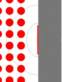
3 Carsten patents to reduce fringing loss in laminated/tape wound cores, 2013 US Pat. No. 9,123,461B2 US Pat. No. 8,466,766 5 Fringing effect on winding loss Low Permeability Strong field near the gap causes increased eddy current winding loss. Curved field is bad for foil windings: 6


4 One conceptual approach Solid winding. Current flow is attracted to gaps. Amount of current is proportional to gap reluctance. μ r = 1000 μ r = 3 7 Single gap Which winding has larger loss, with the same ac current in each winding? 8


5 Single gap All current flows near the gap. Longer gap Current is spread over a larger area lower loss. Current with small gap is spread wider than gap. 9 Spread of current near a small gap Case 1: Winding close to gap. Current spreads beyond the edges of the gap according to the skin depth δ δ δ δ 10


6 Spread of current near a small gap Case 2: Small skin depth; winding spaced from gap. Current spreads over a width ~3s. s 3s 11 One design approach: Spread several gaps evenly: Spacing x between gaps. Distance x/2 from edge of winding. Choose spacing s < x/3. Current distribution is not perfect, but pools of current overlap and impact on loss is small. For details, see [1] Jiankun Hu, C. R. Sullivan, AC Resistance of Planar Power Inductors and the Quasidistributed Gap Technique, IEEE Tran. on Power Electr., 16(4), pp , s x/2 x 12


7 Are all equal spacings gaps equal? Current spreads to both sides of gap. Position accordingly: x/2 on edges. x/2 x y y 25% worse 14% worse 13 A second conceptual approach MMF across gap = MMF generated by the winding. Replace gap with a single turn ribbon carrying a current NI. The field is identical. 14


8 Effect of gap length Same NI in ribbon representing the gap more concentrated vs. more widely spread out. Easy to see that the longer gap will have a less intense fringing field near the gap. Far from the gap, the two are identical. 15 Effect of gap length Same NI in ribbon representing the gap more concentrated vs. more widely spread out. Easy to see that the longer gap will have a less intense fringing field near the gap. Far from the gap, the two are identical. 16


9 Approaching distributed gap Low Permeability 17 Winding shape optimization Shape winding configuration to work with curved gap field. Applies to round wire and litz wire, not foil. Can actually work better than a distributed gap! Ad hoc approach common, but full optimization is available. 18
10 Examples of optimized shapes Dartmouth shapeopt software, available free on our web site. gap wire empty hw dimension (mm) hw dimension (mm) hw dimension (mm) hw dimension (mm) 10 khz 50 khz 100 khz 200 khz 19 How much benefit from shape optimization? Compare designs optimized based on 1 D analysis to true shapeoptimized designs. Up to 4X improvement. AWG 38 strand litz. Optimization tool available for download or on our site References


11 Shaped foil winding Single layer performance like helical winding high frequency current on tips on each turn. Size of cutout optimized for Rac vs. Rdc tradeoff. Expensive to build, but there s a commercial proprietary configuration with similar performance that s cheaper to build. 21 How much benefit? Optimum cutout size depends on ripple ratio Contour lines of total power loss at 20% ripple The optimum circular cutout reduces loss by 63%. References 5. 22


![simple calculation from [1].](/docs-images/95/124406673/images/12-3.jpg "Extra core loss in laminated/tape wound")


12 Conclusions I Lower air gap reluctance than simple predictions. Calculations are rarely needed. If needed, the appendix has an accurate, simple calculation from [1]. Extra core loss in laminated/tape wound cores: eddy currents. Some mitigation options: US Pat. No. 8,466,766 US Pat. No. 9,123,461B2 23 Conclusions II Current flows near the gaps. A wider gap lowers resistance. Spacing s > x/3 is a good rule. Not all equally spaced gaps are equal first gap x/2 from edge. Shaped windings with a single gap. x 24
![References [1] Jiankun Hu, C. R. Sullivan, AC Resistance of Planar Power Inductors and the Quasidistributed Gap Technique, IEEE Tran. on Power Electr., 16(4), pp. 558 567, 2001. https://engineering.](/docs-images/95/124406673/images/13-0.jpg "dartmouth.edu/inductor/papers/qdgj.pdf [2] Jiankun Hu, C. R.")
13 References [1] Jiankun Hu, C. R. Sullivan, AC Resistance of Planar Power Inductors and the Quasidistributed Gap Technique, IEEE Tran. on Power Electr., 16(4), pp , [2] Jiankun Hu, C. R. Sullivan, Analytical Method for Generalization of Numerically Optimized Inductor Winding Shapes, IEEE Power Electronics Specialists Conference, pp , June [3] Jiankun Hu, C. R. Sullivan, Optimization of Shapes for Round Wire, High Frequency Gapped Inductor Windings, IEEE Industry Applications Society Annual Meeting, pp , Oct [4] C. R. Sullivan, J. D. McCurdy, R. A. Jensen, Analysis of Minimum Cost in Shape Optimized Litz Wire Inductor Windings, IEEE Power Electronics Specialists Conference, June [5] J. D. Pollock, C. R. Sullivan, Loss Models for Shaped Foil Windings on Low Permeability Cores, IEEE Power Electronics Specialists Conference, pp , June [6] J. D. Pollock, C. R. Sullivan, Modelling Foil Winding Configurations with Low AC and DC Resistance, IEEE Power Electronics Specialists Conference, pp , June [7] J. Pollock, C. R. Sullivan, Gapped Inductor Foil Windings with Low AC and DC Resistance, IEEE Industry Applications Society Annual Meeting, pp , Oct [8] Lundquist, Weyman, Vivien Yang, and Carl Castro. "Low AC resistance foil cut inductor." Energy Conversion Congress and Exposition (ECCE), 2014 IEEE. IEEE, Another example Both gaps are small enough that it doesn t matter much. Shorter gap is worse mω 2.80 mω 26
 k = 1.")
14 Fringing reluctance calculation where p = perimeter = 2(w+d) k =
Core Loss Initiative: Technical
 Core Loss Initiative: Technical Prof. Charles R. Sullivan chrs@dartmouth.edu Dartmouth Magnetics and Power Electronics Research Group 1 Saturday workshop summary Morning topic: Core loss Afternoon topic:
Windings for High Frequency
 Windings for High Frequency Charles R. Sullivan chrs@dartmouth.edu Dartmouth Magnetics and Power Electronics Research Group http://power.engineering.dartmouth.edu 1 The Issue The best-available technology
West Coast Magnetics. Advancing Power Electronics FOIL WINDINGS FOR SMPS INDUCTORS AND TRANSFORMERS. Weyman Lundquist, CEO and Engineering Manager
 1 West Coast Magnetics Advancing Power Electronics FOIL WINDINGS FOR SMPS INDUCTORS AND TRANSFORMERS Weyman Lundquist, CEO and Engineering Manager TYPES OF WINDINGS 2 Solid wire Lowest cost Low DC resistance
Low AC Resistance Foil Cut Inductor
 Low AC Resistance Foil Cut Inductor West Coast Magnetics Weyman Lundquist, Vivien Yang, and Carl Castro West Coast Magnetics Stockton, CA, USA wlundquist@wcmagnetics.com, vyang@wcmagnetics.com, and ccastro@wcmagnetics.com.
A Fresh Look at Design of Buck and Boost inductors for SMPS Converters
 A Fresh Look at Design of Buck and Boost inductors for SMPS Converters Authors: Weyman Lundquist, Carl Castro, both employees of West Coast Magnetics. Inductors are a critical component in buck and boost
Optimized Magnetic Components Improve Efficiency of Compact Fluorescent Lamps
 Optimized Magnetic Components Improve Efficiency of Compact Fluorescent Lamps J. D. Pollock C. R. Sullivan Found in IEEE Industry Applications Society Annual Meeting, Oct. 2006, pp. 265 269. c 2006 IEEE.
Core Loss Initiative: Technical
 Core Loss Initiative: Technical Prof. Charles R. Sullivan chrs@dartmouth.edu Dartmouth Magnetics and Power Electronics Research Group http://power.engineering.dartmouth.edu 1 Saturday PSMA/PELS Magnetics
HOME APPLICATION NOTES
 HOME APPLICATION NOTES INDUCTOR DESIGNS FOR HIGH FREQUENCIES Powdered Iron "Flux Paths" can Eliminate Eddy Current 'Gap Effect' Winding Losses INTRODUCTION by Bruce Carsten for: MICROMETALS, Inc. There
Using Dielectric Losses to De-Ice Power Transmission Lines with 100 khz High-Voltage Excitation
 Using Dielectric Losses to De-Ice Power Transmission Lines with 100 khz High-Voltage Excitation J. D. McCurdy C. R. Sullivan V. F. Petrenko Found in IEEE Industry Applications Society Annual Meeting, Oct.
Core Loss Initiative: Technical
 Core Loss Initiative: Technical Prof. Charles R. Sullivan chrs@dartmouth.edu Dartmouth Magnetics and Power E l ectro n i c s Re s e a rc h G ro u p http://power.engineering.dartmouth.edu 1 Saturday PSMA/PELS
Impact of Fringing Effects on the Design of DC-DC Converters
 Impact of Fringing Effects on the Design of DC-DC Converters Michael Seeman, Ph.D. Founder / CEO. 2018 APEC PSMA/PELS 2018. Outline Fringe-field loss: What does a power supply designer need to know? Which
Analytical Model for Effects of Twisting on Litz-Wire Losses
 Analytical Model for Effects of Twisting on Litz-Wire Losses Charles R. Sullivan Thayer School of Engineering at Dartmouth 4 Engineering Drive, Hanover, NH 3755, USA Email: charles.r.sullivan@dartmouth.edu
High Frequency Passive Components: a critical challenge for power electronics
 High Frequency Passive Components: a critical challenge for power electronics Prof. Charles R. Sullivan chrs@dartmouth.edu Dartmouth Magnetics and Power Electronics Research Group http://power.engineering.dartmouth.edu
Analysis of High Efficiency Multistage Matching Networks with Volume Constraint
 Analysis of High Efficiency Multistage Matching Networks with Volume Constraint Phyo Aung Kyaw, Aaron.F. Stein, Charles R. Sullivan Thayer School of Engineering at Dartmouth Hanover, NH 03755, USA {phyo.a.kyaw.th,
Optimizing Custom Magnetics for High-Performance Power Supplies
 Optimizing Custom Magnetics for High-Performance Power Supplies Michael Seeman, Ph.D. Founder / CEO. mike@eta1power.com April 2018 PELS Seminar 2018. Outline What is Power Supply Optimization? Performance
Optimization of Shapes for Round Wire, High Frequency Gapped Inductor Windings
 Optimization of Shapes for Round Wire, High Frequency Gapped Inductor Windings Jiankun Hu C. R. Sullivan Found in IEEE Industry Applications Society Annual Meeting, Oct. 1998, pp. 907 911. c 1998 IEEE.
A High Efficient Integrated Planar Transformer for Primary-Parallel Isolated Boost Converters
 A High Efficient Integrated Planar Transformer for Primary-Parallel Isolated Boost Converters Gokhan Sen 1, Ziwei Ouyang 1, Ole C. Thomsen 1, Michael A. E. Andersen 1, and Lars Møller 2 1. Department of
Comparison of Loss in Single-Layer and Multi-Layer Windings with a DC Component
 Comparison of Loss in Single-Layer and Multi-Layer Windings with a DC Component M. E. Dale C. R. Sullivan Found in IEEE Industry Applications Society Annual Meeting, Oct. 26, pp. 87 875. c 26 IEEE. Personal
LEAKAGE FLUX CONSIDERATIONS ON KOOL Mµ E CORES
 LEAKAGE FLUX CONSIDERATIONS ON E CORES Michael W. Horgan Senior Applications Engineer Magnetics Division of Spang & Co. Butler, PA 163 Abstract Kool Mu, a Silicon-Aluminum-Iron powder, is a popular soft
Simplified Design Method for Litz Wire
 Simplified Design Method for Litz Wire Charles R. Sullivan Thayer School of Engineering at Dartmouth Hanover, NH, USA Email: charles.r.sullivan@dartmouth.edu Abstract A simplified approach to choosing
R. W. Erickson. Department of Electrical, Computer, and Energy Engineering University of Colorado, Boulder
 R. W. Erickson Department of Electrical, Computer, and Energy Engineering University of Colorado, Boulder 13.3.2 Low-frequency copper loss DC resistance of wire R = ρ l b A w where A w is the wire bare
Overview of Modelling Methods
 Overview of Modelling Methods Prof. Charles R. Sullivan chrs@dartmouth.edu Dartmouth Magnetics and Power El ec tr oni c s Res ea r c h Gr oup http://power.engineering.dartmouth.edu 1 Winding models vs.
Measurements and Application Considerations of Magnetic Materials at High- and Very-High Frequencies
 Massachusetts Institute of Technology Power Electronics Research Group Measurements and Application Considerations of Magnetic Materials at High- and Very-High Frequencies David Perreault Presented at:
R. W. Erickson. Department of Electrical, Computer, and Energy Engineering University of Colorado, Boulder
 R. W. Erickson Department of Electrical, Computer, and Energy Engineering University of Colorado, Boulder 13.2.3 Leakage inductances + v 1 (t) i 1 (t) Φ l1 Φ M Φ l2 i 2 (t) + v 2 (t) Φ l1 Φ l2 i 1 (t)
University of Bristol - Explore Bristol Research. Peer reviewed version. Link to published version (if available): /IEMDC.2017.
: /IEMDC.2017.") Simpson, N., & Mellor, P. H. (217). Additive manufacturing of shaped profile windings for minimal AC loss in gapped inductors. In 217 IEEE International Electric Machines and Drives Conference (IEMDC 217)
Simpson, N., & Mellor, P. H. (217). Additive manufacturing of shaped profile windings for minimal AC loss in gapped inductors. In 217 IEEE International Electric Machines and Drives Conference (IEMDC 217)
Improved High-Frequency Planar Transformer for Line Level Control (LLC) Resonant Converters
 Resonant Converters") Improved High-Frequency Planar Transformer for Line Level Control (LLC) Resonant Converters Author Water, Wayne, Lu, Junwei Published 2013 Journal Title IEEE Magnetics Letters DOI https://doi.org/10.1109/lmag.2013.2284767
Improved High-Frequency Planar Transformer for Line Level Control (LLC) Resonant Converters Author Water, Wayne, Lu, Junwei Published 2013 Journal Title IEEE Magnetics Letters DOI https://doi.org/10.1109/lmag.2013.2284767
An equivalent complex permeability model for litz-wire windings
 An equivalent complex permeability model for litz-wire windings Xi Nan C. R. Sullivan Found in Fortieth IEEE Industry Applications Society Annual Meeting, Oct. 25, pp. 2229 2235. c 25 IEEE. Personal use
Designers Series XIII
 Designers Series XIII 1 We have had many requests over the last few years to cover magnetics design in our magazine. It is a topic that we focus on for two full days in our design workshops, and it has
Switch Mode Power Supplies and their Magnetics
 Switch Mode Power Supplies and their Magnetics Many factors must be considered by designers when choosing the magnetic components required in today s electronic power supplies In today s day and age the
General Comparison of Power Loss in Single-Layer and Multi-Layer Windings
 General Comparison of Power Loss in Single-Layer and Multi-Layer Windings M. E. Dale C. R. Sullivan Found in IEEE Power Electronics Specialists Conference, June 005, pp. 5 59. c 005 IEEE. Personal use
A Two-Dimensional Equivalent Complex Permeability Model for Round-Wire Windings
 A Two-Dimensional Equivalent Complex Permeability Model for Round-Wire Windings Xi Nan C. R. Sullivan Found in IEEE Power Electronics Specialists Conference, June 25, pp. 63 68. c 25 IEEE. Personal use
Iron Powder Cores for High Q Inductors By: Jim Cox - Micrometals, Inc.
 HOME APPLICATION NOTES Iron Powder Cores for High Q Inductors By: Jim Cox - Micrometals, Inc. SUBJECT: A brief overview will be given of the development of carbonyl iron powders. We will show how the magnetic
Iron Powder Core Selection For RF Power Applications. Jim Cox Micrometals, Inc. Anaheim, CA
 HOME APPLICATION NOTES Iron Powder Core Selection For RF Power Applications Jim Cox Micrometals, Inc. Anaheim, CA Purpose: The purpose of this article is to present new information that will allow the
Magnetics Design. Specification, Performance and Economics
 Magnetics Design Specification, Performance and Economics W H I T E P A P E R MAGNETICS DESIGN SPECIFICATION, PERFORMANCE AND ECONOMICS By Paul Castillo Applications Engineer Datatronics Introduction The
Radio Frequency Electronics
 Radio Frequency Electronics Preliminaries II Guglielmo Giovanni Maria Marconi Thought off by many people as the inventor of radio Pioneer in long-distance radio communications Shared Nobel Prize in 1909
STUDY AND DESIGN ASPECTS OF INDUCTORS FOR DC-DC CONVERTER
 STUDY AND DESIGN ASPECTS OF INDUCTORS FOR DC-DC CONVERTER 1 Nithya Subramanian, 2 R. Seyezhai 1 UG Student, Department of EEE, SSN College of Engineering, Chennai 2 Associate Professor, Department of EEE,
TUTORIAL 5997 THE BENEFITS OF THE COUPLED INDUCTOR TECHNOLOGY
 Keywords: coupled inductors, current-ripple cancellation, guidelines, coupled inductor benefits, multiphase buck, transient improvement, size reduction, efficiency improvement, reduction of output capacitance
Package and Integration Technology in Point-of-load Converters. Laili Wang Xi an Jiaotong University Sumida Technology
 Package and Integration Technology in Point-of-load Converters Laili Wang Xi an Jiaotong University Sumida Technology Content Introduction Multi-permeability distributed air-gap inductor Multi-permeability
Published in: Proceedings of the 29th Annual IEEE Applied Power Electronics Conference and Exposition, APEC 2014.
 Aalborg Universitet Method for introducing bias magnetization in ungaped cores Aguilar, Andres Revilla; Munk-Nielsen, Stig Published in: Proceedings of the 29th Annual IEEE Applied Power Electronics Conference
Investigation of a Hybrid Winding Concept for Toroidal Inductors Using 3D Finite Element Modeling
 Investigation of a Hybrid Winding Concept for Toroidal Inductors Using 3D Finite Element Modeling H. Schneider 1, T. Andersen 1, J. D. Mønster 1, M. P. Madsen 1, A. Knott 1, M. A. E. Andersen 1 1 Technical
High Current Inductor Design for MHz Switching
 High Current Inductor Design for MHz Switching M. Duffy *, C. Collins *,F.M.F.Rhen **,P.McCloskey **,S.Roy ** * Power and Energy Research Centre, NUI Galway, Ireland ** Tyndall National Institute, Cork,
MAGNETIC components (e.g. inductors and transformers)
") IEEE Transactions on Power Electronics (to appear) 1 Measurements and Performance Factor Comparisons of Magnetic Materials at High Frequency Alex J. Hanson, Student Member, IEEE, Julia A. Belk, Student
IEEE Transactions on Power Electronics (to appear) 1 Measurements and Performance Factor Comparisons of Magnetic Materials at High Frequency Alex J. Hanson, Student Member, IEEE, Julia A. Belk, Student
Challenges and Trends in Magnetics
 Challenges and Trends in Magnetics Prof. W. G. Hurley Power Electronics Research Centre National University of Ireland, Galway IEEE Distinguished Lecture The University of Hong Kong 27 May 2016 Outline
Magnetics. Important relationships. Magnetic quantities Analogies to electrical quantities
 Mor M. Peretz, Switch-Mode Power Supplies [3-1] Faraday s and Amper s laws Permeability Inductor Reluctance model Air gap Current crowding Inductor design Skin effect, proximity effect Losses Transformer
Investigation of a Hybrid Winding Concept for Toroidal Inductors using 3D Finite Element Modeling
 Downloaded from orbit.dtu.dk on: Dec 20, 2017 Investigation of a Hybrid Winding Concept for Toroidal Inductors using 3D Finite Element Modeling Schneider, Henrik; Andersen, Thomas; Mønster, Jakob Døllner;
Large Kool Mµ Core Shapes
 Large Kool Mµ Core Shapes TECHNICAL BULLETIN Ideal for high current inductors, large Kool Mµ geometries (E cores, U Cores and Blocks) offer all the advantages of Kool Mµ material, low core loss, excellent
The Future for SMPS Magnetics
 The Future for SMPS Magnetics Weyman Lundquist President and CEO West Coast Magnetics ISO9001:2008 ISO13485 Registered How Much Smaller Can SMPS Power Magnetics Get? How Quickly? How much can we reduce
Large Kool Mµ Core Shapes
 Large Kool Mµ Core Shapes Technical Bulletin Ideal for high current inductors, large Kool Mµ geometries (E cores, Toroids, U Cores and Blocks) offer all the advantages of Kool Mµ material, low core loss,
Large Kool Mµ Core Shapes
 Large Kool Mµ Core Shapes TECHNICAL BULLETIN Ideal for high current inductors, large Kool Mµ geometries (E cores, U Cores and Blocks) offer all the advantages of Kool Mµ material, low core loss, excellent
Flyback transformer design considerations for efficiency and EMI
 Flyback transformer design considerations for efficiency and EMI Isaac Cohen Bernard Keogh Agenda Flyback transformer basics Review of Flyback transformer losses: o Core loss dependence on DC bias, duty
HIGHER power inductors with broad current spectra
 202 IEEE TRANSACTIONS ON POWER ELECTRONICS, VOL. 13, NO. 1, JANUARY 1998 Inductor Design for High-Power Applications with Broad-Spectrum Excitation Ian T. Wallace, Nasser H. Kutkut, Member, IEEE, Subhashish
Picture perfect. Electromagnetic simulations of transformers
 38 ABB review 3 13 Picture perfect Electromagnetic simulations of transformers Daniel Szary, Janusz Duc, Bertrand Poulin, Dietrich Bonmann, Göran Eriksson, Thorsten Steinmetz, Abdolhamid Shoory Power transformers
Thin Self-Resonant Structures with a High-Q for Wireless Power Transfer
 Thin Self-Resonant Structures with a High-Q for Wireless Power Transfer Aaron L.F. Stein Phyo Aung Kyaw Jesse Feldman-Stein Charles R. Sullivan Thayer School of Engineering, Dartmouth College, Hanover,
Topic 4 Practical Magnetic Design: Inductors and Coupled Inductors
 Topic 4 Practical Magnetic Design: Inductors and Coupled Inductors Louis Diana Agenda Theory of operation and design equations Design flow diagram discussion Inductance calculations Ampere s law for magnetizing
Finite Element Analysis (FEA) software. Magnetic component design. 3D Electromagnetic Simulation Allows Reduction of AC Copper Losses
 software. Magnetic component design. 3D Electromagnetic Simulation Allows Reduction of AC Copper Losses") ABSTRACT AC currents in multiple layers in the transformer window can increase copper losses significantly due to the proximity effect. Traditionally used Dowell s curves show that the phenomenon starts
ABSTRACT AC currents in multiple layers in the transformer window can increase copper losses significantly due to the proximity effect. Traditionally used Dowell s curves show that the phenomenon starts
Renco Electronics, Inc.
 Abstract The operating frequency of most electronic circuits has been increasing since the late 1950 s. While the increase in frequency has reduced the overall weight and size of most consumer electronics
A Step-by-Step Guide to Extracting Winding Resistance from an Impedance Measurement
 A Step-by-Step Guide to Extracting Winding Resistance from an Measurement Benedict X. Foo Aaron L.F. Stein Charles R. Sullivan Thayer School of Engineering Dartmouth College Hanover, NH 03755 USA Email:
High-Q Self-Resonant Structure for Wireless Power Transfer
 High-Q Self-Resonant Structure for Wireless Power Transfer Aaron L.F. Stein Phyo Aung Kyaw Charles R. Sullivan Thayer School of Engineering Dartmouth College Hanover, NH 03755 USA Email: {Aaron.L.Stein,
Induction heating of internal
 OPTIMAL DESIGN OF INTERNAL INDUCTION COILS The induction heating of internal surfaces is more complicated than heating external ones. The three main types of internal induction coils each has its advantages
Achieving High Power Density Designs in DC-DC Converters
 Achieving High Power Density Designs in DC-DC Converters Agenda Marketing / Product Requirement Design Decision Making Translating Requirements to Specifications Passive Losses Active Losses Layout / Thermal
GeckoMAGNETICS Modeling Inductive Components
 GeckoMAGNETICS is a tool that enables fast, accurate and user-friendly modelling and pareto-optimal design of inductive power components. 4) A material and core database (GeckoDB), which is a part of the
Multi-Chambered Planar Magnetics Design Techniques
 This paper was originally published in Volume One of the Proceedings of the IEEE Power Electronics Specialists Conference held in Galway, Ireland during the week of June 18-23, 2000. Multi-Chambered Planar
Development and verification of printed circuit board toroidal transformer model
 Development and verification of printed circuit board toroidal transformer model Jens Pejtersen, Jakob Døler Mønster and Arnold Knott DTU Electrical Engineering, Technical University of Denmark Ørsteds
Integrated Inductors with Magnetic Materials for On-Chip Power Conversion
 Integrated Inductors with Magnetic Materials for On-Chip Power Conversion Donald S. Gardner Collaborators: Gerhard Schrom, Fabrice Paillet, Tanay Karnik, Shekhar Borkar Circuits Research Lab & Future Technology
Outcomes from this session
 Outcomes from this session At the end of this session you should be able to Understand what is meant by the term losses. Iron Losses There are three types of iron losses Eddy current losses Hysteresis
Design of Low-Profile Integrated Transformer and Inductor for Substrate-Embedding in 1-5kW Isolated GaN DC-DC Converters
 Design of Low-Profile Integrated Transformer and Inductor for Substrate-Embedding in 1-5kW Isolated GaN DC-DC Converters Haksun Lee, Vanessa Smet, P. M. Raj, Rao Tummala 3D Systems Packaging Research Center
Selecting Magnetics for High Frequency Converters Practical Hints and Suggestions for Getting Started. Industry Session on Magnetics APEC 2016
 Practical Hints and Suggestions for Getting Started Industry Session on Magnetics APEC 2016 The Challenge: Hypothetically, a small- to medium-sized power converter manufacturer with limited resources is
By Hiroo Sekiya, Chiba University, Chiba, Japan and Marian K. Kazimierzuk, Wright State University, Dayton, OH
 ISSUE: November 2011 Core Geometry Coefficient For Resonant Inductors* By Hiroo Sekiya, Chiba University, Chiba, Japan and Marian K. Kazimierzuk, Wright State University, Dayton, OH A resonant inductor
Glossary of Common Magnetic Terms
 Glossary of Common Magnetic Terms Copyright by Magnelab, Inc. 2009 Air Core A term used when no ferromagnetic core is used to obtain the required magnetic characteristics of a given coil. (see Core) Ampere
Aluminum Windings and Other Strategies for High-Frequency Magnetics Design in an Era of High Copper and Energy Costs
 Aluminum Windings and Other Strategies for High-Frequency Magnetics Design in an Era of High Copper and Energy Costs C. R. Sullivan From IEEE Transactions on Power Electronics, vol. 23, no. 4, pp. 2044
Single-turn and multi-turn coil domains in 3D COMSOL. All rights reserved.
 Single-turn and multi-turn coil domains in 3D 2012 COMSOL. All rights reserved. Introduction This tutorial shows how to use the Single-Turn Coil Domain and Multi-Turn Coil Domain features in COMSOL s Magnetic
Optimization of Stranded-Wire Windings and Comparison with Litz Wire on the Basis of Cost and Loss
 Optimization of Stranded-Wire Windings and Comparison with Litz Wire on the Basis of Cost and Loss Xu Tang C. R. Sullivan Found in IEEE Power Electronics Specialists Conference, June 2004, pp. 854 860.
What is an Inductor? Token Electronics Industry Co., Ltd. Version: January 16, Web:
 Version: January 16, 2017 What is an Inductor? Web: www.token.com.tw Email: rfq@token.com.tw Token Electronics Industry Co., Ltd. Taiwan: No.137, Sec. 1, Zhongxing Rd., Wugu District, New Taipei City,
BGA Solder Balls Formation by Induction Heating
 International Journal of Scientific Research in Knowledge, 2(1), pp. 22-27, 2014 Available online at http://www.ijsrpub.com/ijsrk ISSN: 2322-4541; 2014 IJSRPUB http://dx.doi.org/10.12983/ijsrk-2014-p0022-0027
Frequency, where we are today, and where we need to go
 Frequency, where we are today, and where we need to go Ionel Dan Jitaru Rompower Energy Systems Inc. 6262 N. Swan Rd., Suite 200 Tucson, Arizona 85718 OUTLINE Directions in topologies and operation frequency
Shielding Effect of High Frequency Power Transformers for DC/DC Converters used in Solar PV Systems
 Shielding Effect of High Frequency Power Transformers for DC/DC Converters used in Solar PV Systems Author Stegen, Sascha, Lu, Junwei Published 2010 Conference Title Proceedings of IEEE APEMC2010 DOI https://doiorg/101109/apemc20105475521
A Study on the Transformer Design considering the Inrush Current Reduction in the Arc Welding Machine
 Journal of Magnetics 21(3), 374-378 (2016) ISSN (Print) 1226-1750 ISSN (Online) 2233-6656 http://dx.doi.org/10.4283/jmag.2016.21.3.374 A Study on the Transformer Design considering the Inrush Current Reduction
Modeling, Simulation and Verification of Contactless Power Transfer Systems
 Modeling, Simulation and Verification of Contactless Power Transfer Systems J. Serrano (1,*), M. Pérez-Tarragona (1), C. Carretero (2), J. Acero (1). (1) Department of Electronic Engineering and Communications.
Analysis of Planar E+I and ER+I Transformers for Low-Voltage High-Current DC/DC Converters with Focus on Winding Losses and Leakage Inductance
 Downloaded from orbit.dtu.dk on: Jul 14, 2018 Analysis of Planar E+I and ER+I Transformers for Low-Voltage High-Current DC/DC Converters with Focus on Winding Losses and Leakage Inductance Pittini, Riccardo;
Optimized shield design for reduction of EMF from wireless power transfer systems
 This article has been accepted and published on J-STAGE in advance of copyediting. Content is final as presented. IEICE Electronics Express, Vol.*, No.*, 1 9 Optimized shield design for reduction of EMF
Derivation of Optimum Winding Thickness for Duty Cycle Modulated Current Waveshapes
 Derivation of Optimum Winding Thickness for Duty Cycle Modulated Current Waveshapes J.G. Breslin and W.G. Hurley Power Electronics Research Centre, University College, Galway, lreland Abstract - Increased
TRAFTOR WINDINGS CHANGING THE RULES TOROIDAL INDUCTORS & TRANSFORMERS SOLUTIONS PROVIDER AND MANUFACTURER
 TRAFTOR WINDINGS CHANGING THE RULES TOROIDAL INDUCTORS & TRANSFORMERS SOLUTIONS PROVIDER AND MANUFACTURER PRODUCT RANGE POWER INDUCTORS Toroidal technology, driven by 20 years of R&D. POWER TRANSFORMERS
Core Size Optimisation of Variable Power Inductor in DC-DC Converter
 Core Size Optimisation of Variable Power Inductor in DC-DC Converter Sherina Harilal 1, Ratheesh.M.A 2 P.G. Student, Department of Electrical and Electronics Engineering, Vidya Academy of Science and Technology,
EEE, St Peter s University, India 2 EEE, Vel s University, India
 Torque ripple reduction of switched reluctance motor drives below the base speed using commutation angles control S.Vetriselvan 1, Dr.S.Latha 2, M.Saravanan 3 1, 3 EEE, St Peter s University, India 2 EEE,
PHYS 1442 Section 004 Lecture #15
 PHYS 1442 Section 004 Lecture #15 Monday March 17, 2014 Dr. Andrew Brandt Chapter 21 Generator Transformer Inductance 3/17/2014 1 PHYS 1442-004, Dr. Andrew Brandt Announcements HW8 on Ch 21-22 will be
Gapped ferrite toroids for power inductors. Technical Note
 Gapped ferrite toroids for power inductors Technical Note A Y A G E O C O M P A N Y Gapped ferrite toroids for power inductors Contents Introduction 1 Features 1 Applications 1 Type number structure 1
Accurate Models for Spiral Resonators
 MITSUBISHI ELECTRIC RESEARCH LABORATORIES http://www.merl.com Accurate Models for Spiral Resonators Ellstein, D.; Wang, B.; Teo, K.H. TR1-89 October 1 Abstract Analytically-based circuit models for two
(12) United States Patent (10) Patent No.: US 7,199,695 B1 Zhou et a]. (45) Date of Patent: Apr. 3, 2007
![(12) United States Patent (10) Patent No.: US 7,199,695 B1 Zhou et a]. (45) Date of Patent: Apr. 3, 2007](/thumbs/89/99399796.jpg "(12) United States Patent (10) Patent No.: US 7,199,695 B1 Zhou et a]. (45) Date of Patent: Apr. 3, 2007") US007199695B1 (12) United States Patent (10) Patent No.: US 7,199,695 B1 Zhou et a]. (45) Date of Patent: Apr. 3, 2007 (54) MULTPHASE VOLTAGE REGULATOR 2006/0145800 A1* 7/2006 Dadafsharetal.... 336/82
US007199695B1 (12) United States Patent (10) Patent No.: US 7,199,695 B1 Zhou et a]. (45) Date of Patent: Apr. 3, 2007 (54) MULTPHASE VOLTAGE REGULATOR 2006/0145800 A1* 7/2006 Dadafsharetal.... 336/82
Design procedure for pot-core integrated magnetic component
 Design procedure for pot-core integrated magnetic component Martin Foster, Department of Electronic and Electrical Engineering, University of Sheffield, Mappin Street, Sheffield, United Kingdom, m.p.foster@sheffield.ac.uk
Physically-Based Distributed Models for Multi-Layer Ceramic Capacitors
 Physically-Based Distributed Models for Multi-Layer Ceramic Capacitors Charles R Sullivan and Yuqin Sun Thayer School of Engineering Dartmouth College http://power.thayer.dartmouth.edu/ Introduction Why
An Interleaved Flyback Inverter for Residential Photovoltaic Applications
 An Interleaved Flyback Inverter for Residential Photovoltaic Applications Bunyamin Tamyurek and Bilgehan Kirimer ESKISEHIR OSMANGAZI UNIVERSITY Electrical and Electronics Engineering Department Eskisehir,
PHYS 1444 Section 501 Lecture #20
 PHYS 1444 Section 501 Lecture #0 Monday, Apr. 17, 006 Transformer Generalized Faraday s Law Inductance Mutual Inductance Self Inductance Inductor Energy Stored in the Magnetic Field 1 Announcements Quiz
FERRITE CORE INDUCTOR VALUE VARIATION WITH NUMBER OF TURNS AND DIAMETER OF COPPER WIRE,LENGTH AND DIAMETER OF CORE
 FERRITE CORE INDUCTOR VALUE VARIATION WITH NUMBER OF TURNS AND DIAMETER OF COPPER WIRE,LENGTH AND DIAMETER OF CORE PRJ. NO. 073 PRESENTED BY: OMWENGA EDWIN NYAKUNDI F17/8280/2004 SUPERVISOR : MR. OGABA
Aalborg Universitet. Publication date: Document Version Early version, also known as pre-print. Link to publication from Aalborg University
 Aalborg Universitet Size Reduction of a DC Link Choke Using Saturation Gap and Biasing with Permanent Magnets Aguilar, Andres Revilla; Munk-Nielsen, Stig; Zuccherato, Marco; Thougaard, Hans-Jørgen Published
CH 1. Large coil. Small coil. red. Function generator GND CH 2. black GND
 Experiment 6 Electromagnetic Induction "Concepts without factual content are empty; sense data without concepts are blind... The understanding cannot see. The senses cannot think. By their union only can
Inductor and Transformer Design
 Inductor and Transformer Design 1 Introduction The conditioning of power flow in Power Electronic Systems (PES) is done through the use of electromagnetic elements (inductors and transformers). In this
Experiment 4: Grounding and Shielding
 4-1 Experiment 4: Grounding and Shielding Power System Hot (ed) Neutral (White) Hot (Black) 115V 115V 230V Ground (Green) Service Entrance Load Enclosure Figure 1 Typical residential or commercial AC power
University of Pittsburgh
 University of Pittsburgh Experiment #11 Lab Report Inductance/Transformers Submission Date: 12/04/2017 Instructors: Dr. Minhee Yun John Erickson Yanhao Du Submitted By: Nick Haver & Alex Williams Station
Micro-inductors integrated on silicon for power supply on chip
 Journal of Magnetism and Magnetic Materials 316 (27) e233 e237 www.elsevier.com/locate/jmmm Micro-inductors integrated on silicon for power supply on chip Ningning Wang, Terence O Donnell, Saibal Roy,
2052 IEEE TRANSACTIONS ON POWER ELECTRONICS, VOL. 23, NO. 4, JULY 2008
 2052 IEEE TRANSACTIONS ON POWER ELECTRONICS, VOL. 23, NO. 4, JULY 2008 Extended Theory on the Inductance Calculation of Planar Spiral Windings Including the Effect of Double-Layer Electromagnetic Shield