Laboratory Seven Stepper Motor and Feedback Control
|
|
|
- Clifford Clarke
- 5 years ago
- Views:
Transcription
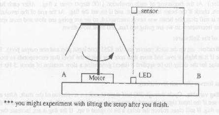
1 EE3940 Microprocessor Systems Laboratory Prof. Andrew Campbell Spring 2003 Groups Names Laboratory Seven Stepper Motor and Feedback Control In this experiment you will experiment with a stepper motor and learn how feedback control is a useful technique in microprocessor subsystems. Feedback control systems form an important class of applications for microprocessors. The microprocessor inputs data from sensors and can quickly calculate control outputs to respond appropriately. We will implement a feedback loop to regulate a shaft velocity in a way that is similar to Watt's "fly-ball governor" that made steam power practical. If all of this doesn t sound very exciting, essentially you will have a straw turning around over a motor with 2 other straws floating in the air until they cut an infrared beam. You will have to sense this interruption in your program and respond by reducing the velocity of the rotation. After finishing this lab you will regret that you will have to leave for the Spring Break. Well, whatever ;) General Description You will cause a stepper motor to rotate its shaft at a software-controlled velocity which is maintained such that the two weights extend to a certain angle. Four output lines from the left hand 8255 of the Micro-Trainer control the four windings of the motor through optoisolators. The opto-isolators have a current rating just enough to carry the current drawn by the motor coils. Details Stepping through the following 8-step sequence (repeatedly) causes the motor to rotate:
2 This is called a half-step pattern because every other pattern has two coils energized, allowing for finer angular resolution when the motor is used for positioning. As we are only concerned with angular velocity (slewing), a four steps pattern should also work -- see optional part 4). The operation can best be understood as if there were an "internal shaft" geared to the "external shaft" but the actual construction is different (a single shaft with no gears). Each step (two half-steps) rotates the motor's internal shaft 90-degrees. For this particular stepper motor, this results in a 3.6 degree motion of the motor's external shaft. An adjustable software delay (to be applied after each half-step) determines the rate of rotation. We don't care if the shaft goes clockwise or counterclockwise. Feedback comes from an optical sensor which is placed to provide a signal at the appropriate velocity as arms on the shaft swing out to interrupt an infrared beam. This signal will be wired to an input bit on the left-hand of Assume that you do not know which voltage level (0 or 5) corresponds to too slow and which corresponds to at or above the correct speed. So your program will read this bit initially and store it, and then test it after each half-step to see if it changes from the inital value. Note that the interruption is never constant, but only occurs at certain points in the revolution when an arm is in the way of the beam. One way to deal with this is the following (but you can try other strategies if you prefer). At the beginning of each revolution (100 steps) clear a flag. After each half step in the revolution, check if the beam is interrupted, and if so, set the flag. At the end of the revolution, check the flag. If it is still clear, the beam was never interrupted, so we are going too slow and must speed up. If it is set, it was interrupted, so we are going too fast, and must slow down. Outline of the Software 1) Initialization: set up the stack pointer and the 8255 (one input port and one output port). Read the input bit to see if it is high or low, and store it to note that is the level that corresponds to too slow. Set an initial value for the delay (to be applied 8 times) generation a slow rotation of about 0.5Hz to the external shaft. 2) Repeat forever (for each revolution): Clear a flag variable. Cycle through 200 half-steps to make a revolution of the shaft. After each half step, check to see if the input signal changed to another level, and if so, set the flag. At the end of the revolution, check the flag. If still clear, reduce the delay a bit to speed it up. If the flag is set, increase the delay a bit to slow down the motor. In either case, if an extreme value is reached, HALT. (Motor out of control or sensor failed). The desired behavior is for it to gradually speed up until it reaches the point where the outstretched weights intercept the sensor beam. Then, the velocity oscillates back and forth around the point at which the beam is just broken. The oscillation will be so small that to the naked eye, the system appears to be rotating at a constant velocity. There will be only 2 setups to run complete tests you can debug your logic with just a stepper motor and a power supply, using a push-button to stimulate the input. When everything appears to be working, download your software onto the machine attached to the complete setup. Displaying the delay value could be a useful feature for debugging Page 2 of 6
3 purposes but there is no simple way for you to do this, as the SCAN routing would take too long. Experiment Milestones 1. Debug your program as best as you can using no stepper motor. The LEDs will show you if you are going through the correct patterns, and if you are speeding up or slowing down. Use one of the Micro-Trainer push-buttons to simulate the input from the optical sensor. Just wire Z0 or Z0* to your selected input bit. It should work with either. Confirm Operation 2. Wire up a borrowed stepper motor through the opto-isolators with a 12V power supply. Note that the 12V circuitry should be completely disconnected from the 5V of the Micro- Trainer. The two grounds do not need to be connected. This is the beauty of the optoisolators -- it should keep you from accidentally melting down any Micro-Trainers. Watch and feel the shaft move, still using the push button for input, to verify the speeds you are using are roughly correct. Confirm Operation 3. Connect to one of the complete setups provided by the TAs (preferably by downloading to one lab station that has a setup) and demonstrate it to the TA. TA signs here 4. Try these 4-step patterns. Comment on any difference you notice. Page 3 of 6
4 OR Answer Page 4 of 6

5 Diagrams Page 5 of 6
6 Page 6 of 6
Lab Exercise 9: Stepper and Servo Motors
 ME 3200 Mechatronics Laboratory Lab Exercise 9: Stepper and Servo Motors Introduction In this laboratory exercise, you will explore some of the properties of stepper and servomotors. These actuators are
Lab 8. Stepper Motor Controller
 Lab 8. Stepper Motor Controller Overview of this Session In this laboratory, you will learn: To continue to use an oscilloscope How to use a Step Motor driver chip. Introduction This lab is focused around
Job Sheet 2 Servo Control
 Job Sheet 2 Servo Control Electrical actuators are replacing hydraulic actuators in many industrial applications. Electric servomotors and linear actuators can perform many of the same physical displacement
Assembly Language. Topic 14 Motion Control. Stepper and Servo Motors
 Assembly Language Topic 14 Motion Control Stepper and Servo Motors Objectives To gain an understanding of the operation of a stepper motor To develop a means to control a stepper motor To gain an understanding
University of Texas at El Paso Electrical and Computer Engineering Department
 University of Texas at El Paso Electrical and Computer Engineering Department EE 3176 Laboratory for Microprocessors I Fall 2016 LAB 05 Pulse Width Modulation Goals: Bonus: Pre Lab Questions: Use Port
Adaptive Touch Sampling for Energy-Efficient Mobile Platforms
 Adaptive Touch Sampling for Energy-Efficient Mobile Platforms Kyungtae Han Intel Labs, USA Alexander W. Min, Dongho Hong, Yong-joon Park Intel Corporation, USA April 16, 2015 Touch Interface in Today s
PART 2 - ACTUATORS. 6.0 Stepper Motors. 6.1 Principle of Operation
 6.1 Principle of Operation PART 2 - ACTUATORS 6.0 The actuator is the device that mechanically drives a dynamic system - Stepper motors are a popular type of actuators - Unlike continuous-drive actuators,
LAB 1 AN EXAMPLE MECHATRONIC SYSTEM: THE FURBY
 LAB 1 AN EXAMPLE MECHATRONIC SYSTEM: THE FURBY Objectives Preparation Tools To see the inner workings of a commercial mechatronic system and to construct a simple manual motor speed controller and current
Quantizer step: volts Input Voltage [V]
![Quantizer step: volts Input Voltage [V]](/thumbs/96/126541381.jpg "Quantizer step: volts Input Voltage [V]") EE 101 Fall 2008 Date: Lab Section # Lab #8 Name: A/D Converter and ECEbot Power Abstract Partner: Autonomous robots need to have a means to sense the world around them. For example, the bumper switches
EE 101 Fall 2008 Date: Lab Section # Lab #8 Name: A/D Converter and ECEbot Power Abstract Partner: Autonomous robots need to have a means to sense the world around them. For example, the bumper switches
The light sensor, rotation sensor, and motors may all be monitored using the view function on the RCX.
 Review the following material on sensors. Discuss how you might use each of these sensors. When you have completed reading through this material, build a robot of your choosing that has 2 motors (connected
EE 314 Spring 2003 Microprocessor Systems
 EE 314 Spring 2003 Microprocessor Systems Laboratory Project #9 Closed Loop Control Overview and Introduction This project will bring together several pieces of software and draw on knowledge gained in
EE 308 Lab Spring 2009
 9S12 Subsystems: Pulse Width Modulation, A/D Converter, and Synchronous Serial Interface In this sequence of three labs you will learn to use three of the MC9S12's hardware subsystems. WEEK 1 Pulse Width
Basic of PCD Series Pulse Control LSIs
 Basic of PCD Series Pulse Control LSIs Nippon Pulse Motor Co., Ltd. Table of Contents 1. What is a PCD? 1 2. Reviewing common terms 1 (1) Reference clock 1 (2) Operating patterns and registers 1 (3) Commands
MAE106 Laboratory Exercises Lab # 5 - PD Control of DC motor position
 MAE106 Laboratory Exercises Lab # 5 - PD Control of DC motor position University of California, Irvine Department of Mechanical and Aerospace Engineering Goals Understand how to implement and tune a PD
Page 1. Relays. Poles and Throws. Relay Types. Common embedded system problem CS/ECE 6780/5780. Al Davis. Terminology used for switches
 Relays CS/ECE 6780/5780 Al Davis Today s topics: Relays & Motors prelude to 5780 Lab 9 Common embedded system problem digital control: relatively small I & V levels controlled device requires significantly
EE 308 Spring S12 SUBSYSTEMS: PULSE WIDTH MODULATION, A/D CONVERTER, AND SYNCHRONOUS SERIAN INTERFACE
 9S12 SUBSYSTEMS: PULSE WIDTH MODULATION, A/D CONVERTER, AND SYNCHRONOUS SERIAN INTERFACE In this sequence of three labs you will learn to use the 9S12 S hardware sybsystem. WEEK 1 PULSE WIDTH MODULATION
Sensors and Sensing Motors, Encoders and Motor Control
 Sensors and Sensing Motors, Encoders and Motor Control Todor Stoyanov Mobile Robotics and Olfaction Lab Center for Applied Autonomous Sensor Systems Örebro University, Sweden todor.stoyanov@oru.se 13.11.2014
Penn State Erie, The Behrend College School of Engineering
 Penn State Erie, The Behrend College School of Engineering EE BD 327 Signals and Control Lab Spring 2008 Lab 9 Ball and Beam Balancing Problem April 10, 17, 24, 2008 Due: May 1, 2008 Number of Lab Periods:
Automatic Railway Gate Control & Track Switching
 Automatic Railway Gate Control & Track Switching ABSTRACT: Present project is designed using 8051 microcontroller to avoid railway accidents happening at unattended railway gates, if implemented in spirit.
Exercise 3-3. Manual Reversing Starters EXERCISE OBJECTIVE DISCUSSION. Build manual reversing starters and understand how they work.
 Exercise 3-3 Manual Reversing Starters EXERCISE OBJECTIVE Build manual reversing starters and understand how they work. DISCUSSION Reversing motor rotation direction is a common operation in industrial
ME 461 Laboratory #5 Characterization and Control of PMDC Motors
 ME 461 Laboratory #5 Characterization and Control of PMDC Motors Goals: 1. Build an op-amp circuit and use it to scale and shift an analog voltage. 2. Calibrate a tachometer and use it to determine motor
EXPERIMENT 6: Advanced I/O Programming
 EXPERIMENT 6: Advanced I/O Programming Objectives: To familiarize students with DC Motor control and Stepper Motor Interfacing. To utilize MikroC and MPLAB for Input Output Interfacing and motor control.
Experiment#6: Speaker Control
 Experiment#6: Speaker Control I. Objectives 1. Describe the operation of the driving circuit for SP1 speaker. II. Circuit Description The circuit of speaker and driver is shown in figure# 1 below. The
Computer Numeric Control
 Computer Numeric Control TA202A 2017-18(2 nd ) Semester Prof. J. Ramkumar Department of Mechanical Engineering IIT Kanpur Computer Numeric Control A system in which actions are controlled by the direct
Lab 5: Inverted Pendulum PID Control
 Lab 5: Inverted Pendulum PID Control In this lab we will be learning about PID (Proportional Integral Derivative) control and using it to keep an inverted pendulum system upright. We chose an inverted
Experiment 9 : Pulse Width Modulation
 Name/NetID: Experiment 9 : Pulse Width Modulation Laboratory Outline In experiment 5 we learned how to control the speed of a DC motor using a variable resistor. This week, we will learn an alternative
ECE 445 Senior Design Laboratory. Fall Individual Progress Report. Automatic Pill Dispenser
 ECE 445 Senior Design Laboratory Fall 2017 Individual Progress Report Automatic Pill Dispenser Iskandar Aripov (aripov2) Team Members: Iskandar Aripov Mattew Colletti Instructor: Prof. Arne Fliflet TA:
PREREQUISITES: MODULE 10: MICROCONTROLLERS II; MODULE 14: DISCRETE COMPONENTS. MODULE 13 (SENSORS) WOULD ALSO BE HELPFUL.
 WOULD ALSO BE HELPFUL.") ELECTROMECHANICAL SYSTEMS PREREQUISITES: MODULE 10: MICROCONTROLLERS II; MODULE 14: DISCRETE COMPONENTS. MODULE 13 (SENSORS) WOULD ALSO BE HELPFUL. OUTLINE OF MODULE 17: What you will learn about in this
ELECTROMECHANICAL SYSTEMS PREREQUISITES: MODULE 10: MICROCONTROLLERS II; MODULE 14: DISCRETE COMPONENTS. MODULE 13 (SENSORS) WOULD ALSO BE HELPFUL. OUTLINE OF MODULE 17: What you will learn about in this
MICROCONTROLLERS Stepper motor control with Sequential Logic Circuits
 PH-315 MICROCONTROLLERS Stepper motor control with Sequential Logic Circuits Portland State University Summary Four sequential digital waveforms are used to control a stepper motor. The main objective
Introduction. Theory of Operation
 Mohan Rokkam Page 1 12/15/2004 Introduction The goal of our project is to design and build an automated shopping cart that follows a shopper around. Ultrasonic waves are used due to the slower speed of
PEAKTRONICS AMC-103 ADDITIONAL FEATURES. AC Motor Controller, 2A AMC-103 AMC-103A AMC-103B
 PEAKTRONICS The Peaktronics AC Motor Controller is a compact module that is intended for controlling small AC actuator motors of up to 2A. The is very well suited for applications where space constraints
Lab 1: Steady State Error and Step Response MAE 433, Spring 2012
 Lab 1: Steady State Error and Step Response MAE 433, Spring 2012 Instructors: Prof. Rowley, Prof. Littman AIs: Brandt Belson, Jonathan Tu Technical staff: Jonathan Prévost Princeton University Feb. 14-17,
1. To study the influence of the gain on the transient response of a position servo. 2. To study the effect of velocity feedback.
 KING FAHD UNIVERSITY OF PETROLEUM & MINERALS Electrical Engineering Department EE 380 - Control Engineering Experiment # 6 Servo Motor Position Control Using a Proportional Controller OBJECTIVES: 1. To
Mechatronics Engineering and Automation Faculty of Engineering, Ain Shams University MCT-151, Spring 2015 Lab-4: Electric Actuators
 Mechatronics Engineering and Automation Faculty of Engineering, Ain Shams University MCT-151, Spring 2015 Lab-4: Electric Actuators Ahmed Okasha, Assistant Lecturer okasha1st@gmail.com Objective Have a
L E C T U R E R, E L E C T R I C A L A N D M I C R O E L E C T R O N I C E N G I N E E R I N G
 P R O F. S L A C K L E C T U R E R, E L E C T R I C A L A N D M I C R O E L E C T R O N I C E N G I N E E R I N G G B S E E E @ R I T. E D U B L D I N G 9, O F F I C E 0 9-3 1 8 9 ( 5 8 5 ) 4 7 5-5 1 0
Exercise 2-2. Antenna Driving System EXERCISE OBJECTIVE DISCUSSION OUTLINE DISCUSSION
 Exercise 2-2 Antenna Driving System EXERCISE OBJECTIVE When you have completed this exercise, you will be familiar with the mechanical aspects and control of a rotating or scanning radar antenna. DISCUSSION
Basic NC and CNC. Dr. J. Ramkumar Professor, Department of Mechanical Engineering Micro machining Lab, I.I.T. Kanpur
 Basic NC and CNC Dr. J. Ramkumar Professor, Department of Mechanical Engineering Micro machining Lab, I.I.T. Kanpur Micro machining Lab, I.I.T. Kanpur Outline 1. Introduction to CNC machine 2. Component
Actuators. EECS461, Lecture 5, updated September 16,
 Actuators The other side of the coin from sensors... Enable a microprocessor to modify the analog world. Examples: - speakers that transform an electrical signal into acoustic energy (sound) - remote control
CSE 3215 Embedded Systems Laboratory Lab 5 Digital Control System
 Introduction CSE 3215 Embedded Systems Laboratory Lab 5 Digital Control System The purpose of this lab is to introduce you to digital control systems. The most basic function of a control system is to
Chapter 7: The motors of the robot
 Chapter 7: The motors of the robot Learn about different types of motors Learn to control different kinds of motors using open-loop and closedloop control Learn to use motors in robot building 7.1 Introduction
Feedback Devices. By John Mazurkiewicz. Baldor Electric
 Feedback Devices By John Mazurkiewicz Baldor Electric Closed loop systems use feedback signals for stabilization, speed and position information. There are a variety of devices to provide this data, such
GE 320: Introduction to Control Systems
 GE 320: Introduction to Control Systems Laboratory Section Manual 1 Welcome to GE 320.. 1 www.softbankrobotics.com 1 1 Introduction This section summarizes the course content and outlines the general procedure
ESO 210 Introduction to Electrical Engineering
 ESO 210 Introduction to Electrical Engineering Lecture-12 Three Phase AC Circuits Three Phase AC Supply 2 3 In general, three-phase systems are preferred over single-phase systems for the transmission
CIS009-2, Mechatronics Signals & Motors
 CIS009-2, Signals & Motors Bedfordshire 13 th December 2012 Outline 1 2 3 4 5 6 7 8 3 Signals Two types of signals exist: 4 Bedfordshire 52 Analogue signal In an analogue signal voltages and currents continuously
Sensors and Sensing Motors, Encoders and Motor Control
 Sensors and Sensing Motors, Encoders and Motor Control Todor Stoyanov Mobile Robotics and Olfaction Lab Center for Applied Autonomous Sensor Systems Örebro University, Sweden todor.stoyanov@oru.se 05.11.2015
ELECTRICAL ENGINEERING TECHNOLOGY PROGRAM EET 433 CONTROL SYSTEMS ANALYSIS AND DESIGN LABORATORY EXPERIENCES
 ELECTRICAL ENGINEERING TECHNOLOGY PROGRAM EET 433 CONTROL SYSTEMS ANALYSIS AND DESIGN LABORATORY EXPERIENCES EXPERIMENT 4: ERROR SIGNAL CHARACTERIZATION In this laboratory experience we will use the two
EE 340L Experiment 6: Synchronous Generator - Operation with the Grid
 EE 340L Experiment 6: Synchronous Generator - Operation with the Grid The synchronous machine (see Fig. 1) is mechanically coupled to the Four-Quadrant Dynamometer/Power Supply (see Fig. 2) using a timing
Basic Microprocessor Interfacing Trainer Lab Manual
 Basic Microprocessor Interfacing Trainer Lab Manual Control Inputs Microprocessor Data Inputs ff Control Unit '0' Datapath MUX Nextstate Logic State Memory Register Output Logic Control Signals ALU ff
EEE3410 Microcontroller Applications Department of Electrical Engineering Lecture 11 Motor Control
 EEE34 Microcontroller Applications Department of Electrical Engineering Lecture Motor Control Week 3 EEE34 Microcontroller Applications In this Lecture. Interface 85 with the following output Devices Optoisolator
MicroManager. Torque Mode CTCW/Loadcell Control. Instruction Manual MM3000-CTCW
 MicroManager Torque Mode CTCW/Loadcell Control Instruction Manual MM3000-CTCW Table of Contents 1. General Description... 5 2. Specifications... 5 2.1 Electrical... 5 2.2 Physical... 6 3. Installation...
Exercise 6. Range and Angle Tracking Performance (Radar-Dependent Errors) EXERCISE OBJECTIVE
 EXERCISE OBJECTIVE") Exercise 6 Range and Angle Tracking Performance EXERCISE OBJECTIVE When you have completed this exercise, you will be familiar with the radardependent sources of error which limit range and angle tracking
Exercise 6 Range and Angle Tracking Performance EXERCISE OBJECTIVE When you have completed this exercise, you will be familiar with the radardependent sources of error which limit range and angle tracking
ISONIC PA AUT Spiral Scan Inspection of Tubular Parts Operating Manual and Inspection Procedure Rev 1.00 Sonotron NDT
 ISONIC PA AUT Spiral Scan Inspection of Tubular Parts Operating Manual and Inspection Procedure Rev 1.00 Sonotron NDT General ISONIC PA AUT Spiral Scan Inspection Application was designed on the platform
Validation Document. ELEC 491 Capstone Proposal - Dynamic Projector Mount Project. Andy Kwan Smaran Karimbil Siamak Rahmanian Dante Ye
 Validation Document ELEC 491 Capstone Proposal - Dynamic Projector Mount Project Andy Kwan Smaran Karimbil Siamak Rahmanian Dante Ye Executive Summary: The purpose of this document is to describe the tests
2.017 DESIGN OF ELECTROMECHANICAL ROBOTIC SYSTEMS Fall 2009 Lab 4: Motor Control. October 5, 2009 Dr. Harrison H. Chin
 2.017 DESIGN OF ELECTROMECHANICAL ROBOTIC SYSTEMS Fall 2009 Lab 4: Motor Control October 5, 2009 Dr. Harrison H. Chin Formal Labs 1. Microcontrollers Introduction to microcontrollers Arduino microcontroller
Chapter 14. using data wires
 Chapter 14. using data wires In this fifth part of the book, you ll learn how to use data wires (this chapter), Data Operations blocks (Chapter 15), and variables (Chapter 16) to create more advanced programs
The Mechatronics Sorter Team Members John Valdez Hugo Ramirez Peter Verbiest Quyen Chu
 The Mechatronics Sorter Team Members John Valdez Hugo Ramirez Peter Verbiest Quyen Chu Professor B.J. Furman Course ME 106 Date 12.9.99 Table of Contents Description Section Title Page - Table of Contents
Lab book. Exploring Robotics (CORC3303)
") Lab book Exploring Robotics (CORC3303) Dept of Computer and Information Science Brooklyn College of the City University of New York updated: Fall 2011 / Professor Elizabeth Sklar UNIT A Lab, part 1 : Robot
Lab book Exploring Robotics (CORC3303) Dept of Computer and Information Science Brooklyn College of the City University of New York updated: Fall 2011 / Professor Elizabeth Sklar UNIT A Lab, part 1 : Robot
LAB 3 TIMER FUNCTIONS: BOLT DROP AND SQUARE WAVE
 LAB 3 TIMER FUNCTIONS: BOLT DROP AND SQUARE WAVE OBJECTIVE This lab will use MC6811 to perform time measurements. Part I will perform time measurements on a dropping bolt using input capture (IC) timer
Electronic Systems - B1 23/04/ /04/ SisElnB DDC. Chapter 2
 Politecnico di Torino - ICT school Goup B - goals ELECTRONIC SYSTEMS B INFORMATION PROCESSING B.1 Systems, sensors, and actuators» System block diagram» Analog and digital signals» Examples of sensors»
ELECTRONIC SYSTEMS. Introduction. B1 - Sensors and actuators. Introduction
 Politecnico di Torino - ICT school Goup B - goals ELECTRONIC SYSTEMS B INFORMATION PROCESSING B.1 Systems, sensors, and actuators» System block diagram» Analog and digital signals» Examples of sensors»
Lecture#1 Handout. Plant has one or more inputs and one or more outputs, which can be represented by a block, as shown below.
 Lecture#1 Handout Introduction A system or a process or a plant is a segment of environment that is under consideration (working definition). Control is a term that describes the process of forcing a system
Solar Mobius Final Report. Team 1821 Members: Advisor. Sponsor
 Senior Design II ECE 4902 Spring 2018 Solar Mobius Final Report Team 1821 Members: James Fisher (CMPE) David Pettibone (EE) George Oppong (EE) Advisor Professor Ali Bazzi Sponsor University of Connecticut
SRVODRV REV7 INSTALLATION NOTES
 SRVODRV-8020 -REV7 INSTALLATION NOTES Thank you for purchasing the SRVODRV -8020 drive. The SRVODRV -8020 DC servo drive is warranted to be free of manufacturing defects for 1 year from the date of purchase.
DR3535 DR3535-O. Hardware Reference Manual. Document Revision A7 May 16, 2018 MICROKINETICS CORPORATION
 -O Hardware Reference Manual Document Revision A7 May 16, 2018 MICROKINETICS CORPORATION 3380 Town Point Drive Suite 330 Kennesaw, GA 30144 Tel: (770) 422-7845 Fax: (770) 422-7854 www.microkinetics.com
Introduction to project hardware
 ECE2883 HP: Lab 2- nonsme Introduction to project hardware Using the oscilloscope, solenoids, audio transducers, motors In the following exercises, you will use some of the project hardware devices, which
Introduction to the ME2110 Kit. Controller Box Electro Mechanical Actuators & Sensors Pneumatics
 Introduction to the ME2110 Kit Controller Box Electro Mechanical Actuators & Sensors Pneumatics Features of the Controller Box BASIC Stamp II-SX microcontroller Interfaces with various external devices
ELECTRICAL POWER TRANSMISSION TRAINER
 ELECTRICAL POWER TRANSMISSION TRAINER ELECTRICAL POWER TRANSMISSION TRAINER This training system has been designed to provide the students with a fully comprehensive knowledge in Electrical Power Engineering
Momentum and Impulse. Objective. Theory. Investigate the relationship between impulse and momentum.
 [For International Campus Lab ONLY] Objective Investigate the relationship between impulse and momentum. Theory ----------------------------- Reference -------------------------- Young & Freedman, University
DM8010 tm. Hardware Reference Manual. Document Revision B3 May 16, 2018
 tm Hardware Reference Manual Document Revision B3 May 16, 2018 MICROKINETICS CORPORATION 3380 Town Point Drive Suite 330 Kennesaw, Georgia 30144 Tel: (770) 422-7845 Fax: (770) 422-7854 Table Of Contents
EE-110 Introduction to Engineering & Laboratory Experience Saeid Rahimi, Ph.D. Labs Introduction to Arduino
 EE-110 Introduction to Engineering & Laboratory Experience Saeid Rahimi, Ph.D. Labs 10-11 Introduction to Arduino In this lab we will introduce the idea of using a microcontroller as a tool for controlling
TEACHING PLC IN AUTOMATION --A Case Study
 TEACHING PLC IN AUTOMATION --A Case Study Dr. George Yang, Assistant Professor And Dr. Yona Rasis, Assistant Professor Department of Engineering Technology Missouri Western State College 4525 Downs Drive
3. What is the difference between Switched Reluctance motor and variable reluctance stepper motor?(may12)
") EE6703 SPECIAL ELECTRICAL MACHINES UNIT III SWITCHED RELUCTANCE MOTOR PART A 1. What is switched reluctance motor? The switched reluctance motor is a doubly salient, singly excited motor. This means that
EE6703 SPECIAL ELECTRICAL MACHINES UNIT III SWITCHED RELUCTANCE MOTOR PART A 1. What is switched reluctance motor? The switched reluctance motor is a doubly salient, singly excited motor. This means that
Chapter 7: Instrumentation systems
 Chapter 7: Instrumentation systems Learning Objectives: At the end of this topic you will be able to: describe the use of the following analogue sensors: thermistors strain gauge describe the use of the
Stepping motor controlling apparatus
 Stepping motor controlling apparatus Ngoc Quy, Le*, and Jae Wook, Jeon** School of Information and Computer Engineering, SungKyunKwan University, 300 Chunchundong, Jangangu, Suwon, Gyeonggi 440746, Korea
Stepper Motors in C. Unipolar (5 lead) stepper motorr. $1.95 from 100 steps per rotation. 24V / 160mA / 600 gm cm holding 160mA
 stepper motorr. $1.95 from 100 steps per rotation. 24V / 160mA / 600 gm cm holding 160mA") U tepper Motors ugust 22, 2017 tepper Motors in Unipolar (5 lead) stepper motorr. $1.95 from www.mpja.com 100 steps per rotation. 24V / 160m / 600 gm cm holding torque @ 160m stepper motor is a digital
U tepper Motors ugust 22, 2017 tepper Motors in Unipolar (5 lead) stepper motorr. $1.95 from www.mpja.com 100 steps per rotation. 24V / 160m / 600 gm cm holding torque @ 160m stepper motor is a digital
Servo Indexer Reference Guide
 Servo Indexer Reference Guide Generation 2 - Released 1/08 Table of Contents General Description...... 3 Installation...... 4 Getting Started (Quick Start)....... 5 Jog Functions..... 8 Home Utilities......
MicroManager. Velocity Mode PID Dancer/Loadcell Control. Instruction Manual MM3000-PID
 MicroManager Velocity Mode PID Dancer/Loadcell Control Instruction Manual MM3000-PID Table of Contents 1. General Description... 5 2. Specifications... 5 2.1 Electrical... 5 2.2 Physical... 6 3. Installation...
AMC-100 AMC-101 AMC-100 AMC-100B AMC-100D AMC-101 AMC-101B AMC-101D AMC-100A AMC-100C AMC-100E AMC-101A AMC-101C AMC-101E. AC Motor Controllers
 The Indelac / AC Motor Controllers are used for proportional positioning of split phase AC actuator motors. An external command signal of 0-0V, -V, or -0mA can be used to compare to a feedback signal from
Step vs. Servo Selecting the Best
 Step vs. Servo Selecting the Best Dan Jones Over the many years, there have been many technical papers and articles about which motor is the best. The short and sweet answer is let s talk about the application.
Built-in soft-start feature. Up-Slope and Down-Slope. Power-Up safe start feature. Motor will only start if pulse of 1.5ms is detected.
 Thank You for purchasing our TRI-Mode programmable DC Motor Controller. Our DC Motor Controller is the most flexible controller you will find. It is user-programmable and covers most applications. This
DC Motor and Servo motor Control with ARM and Arduino. Created by:
 DC Motor and Servo motor Control with ARM and Arduino Created by: Andrew Kaler (39345) Tucker Boyd (46434) Mohammed Chowdhury (860822) Tazwar Muttaqi (901700) Mark Murdock (98071) May 4th, 2017 Objective
LAB 5: Mobile robots -- Modeling, control and tracking
 LAB 5: Mobile robots -- Modeling, control and tracking Overview In this laboratory experiment, a wheeled mobile robot will be used to illustrate Modeling Independent speed control and steering Longitudinal
DC-Motor Driver circuits
 DC-Mot May 19, 2012 Why is there a need for a motor driver circuit? Normal DC gear-head motors requires current greater than 250mA. ICs like 555 timer, ATmega Microcontroller, 74 series ICs cannot supply
Modeling Position Tracking System with Stepper Motor
 Modeling Position Tracking System with Stepper Motor Shreeji S. Sheth 1, Pankaj Kr. Gupta 2, J. K. Hota 3 Abstract The position tracking system is used in many applications like pointing an antenna towards
Controlling Stepper Motors Using the Power I/O Wildcard
 Mosaic Industries Controlling Stepper Motors Using the Power I/O Wildcard APPLICATION NOTE MI-AN-072 2005-09-15 pkc The Mosaic Stepper Motor The Mosaic stepper motor is a four-phase, unipolar stepping
Studuino Icon Programming Environment Guide
 Studuino Icon Programming Environment Guide Ver 0.9.6 4/17/2014 This manual introduces the Studuino Software environment. As the Studuino programming environment develops, these instructions may be edited
Linear Motion Servo Plants: IP01 or IP02. Linear Experiment #0: Integration with WinCon. IP01 and IP02. Student Handout
 Linear Motion Servo Plants: IP01 or IP02 Linear Experiment #0: Integration with WinCon IP01 and IP02 Student Handout Table of Contents 1. Objectives...1 2. Prerequisites...1 3. References...1 4. Experimental
Supply Kit Project: Pneumatic Launcher
 GEORGIA INSTITUTE OF TECHNOLOGY George W. Woodruff School of Mechanical Engineering ME 2110 Creative Decisions and Design Spring 2010 Supply Kit Project: Pneumatic Launcher In order to successfully design
PID Control with Derivative Filtering and Integral Anti-Windup for a DC Servo
 PID Control with Derivative Filtering and Integral Anti-Windup for a DC Servo Nicanor Quijano and Kevin M. Passino The Ohio State University Department of Electrical Engineering 2015 Neil Avenue, Columbus
Laboratory Exercise 1 Microcontroller Board with Driver Board
 Laboratory Exercise 1 Microcontroller Board with Driver Board The purpose of this lab exercises is to demonstrate how the Microcontroller Board can be used to control motors connected to the Driver Board
G320X MANUAL DC BRUSH SERVO MOTOR DRIVE
 G320X MANUAL DC BRUSH SERVO MOTOR DRIVE Thank you for purchasing the G320X drive. The G320X DC servo drive is warranted to be free of manufacturing defects for 3 years from the date of purchase. Any customer
νµθωερτψυιοπασδφγηϕκλζξχϖβνµθωερτ ψυιοπασδφγηϕκλζξχϖβνµθωερτψυιοπα σδφγηϕκλζξχϖβνµθωερτψυιοπασδφγηϕκ χϖβνµθωερτψυιοπασδφγηϕκλζξχϖβνµθ
 θωερτψυιοπασδφγηϕκλζξχϖβνµθωερτψ υιοπασδφγηϕκλζξχϖβνµθωερτψυιοπασδ φγηϕκλζξχϖβνµθωερτψυιοπασδφγηϕκλζ ξχϖβνµθωερτψυιοπασδφγηϕκλζξχϖβνµ EE 331 Design Project Final Report θωερτψυιοπασδφγηϕκλζξχϖβνµθωερτψ
Intro to Engineering II for ECE: Lab 3 Controlling Servo Motors Erin Webster and Dr. Jay Weitzen, c 2012 All rights reserved
 Lab 3: Controlling Servo Motors Laboratory Objectives: 1) To program the basic stamp to control the motion of a servo 2) To observe the control waveforms as the motion of the servo changes 3) To learn
OPTICS IN MOTION. Introduction: Competing Technologies: 1 of 6 3/18/2012 6:27 PM.
 1 of 6 3/18/2012 6:27 PM OPTICS IN MOTION STANDARD AND CUSTOM FAST STEERING MIRRORS Home Products Contact Tutorial Navigate Our Site 1) Laser Beam Stabilization to design and build a custom 3.5 x 5 inch,
Administrative Notes. DC Motors; Torque and Gearing; Encoders; Motor Control. Today. Early DC Motors. Friday 1pm: Communications lecture
 At Actuation: ti DC Motors; Torque and Gearing; Encoders; Motor Control RSS Lecture 3 Wednesday, 11 Feb 2009 Prof. Seth Teller Administrative Notes Friday 1pm: Communications lecture Discuss: writing up
ServoStep technology
 What means "ServoStep" "ServoStep" in Ever Elettronica's strategy resumes seven keypoints for quality and performances in motion control applications: Stepping motors Fast Forward Feed Full Digital Drive
Your EdVenture into Robotics 10 Lesson plans
 Your EdVenture into Robotics 10 Lesson plans Activity sheets and Worksheets Find Edison Robot @ Search: Edison Robot Call 800.962.4463 or email custserv@ Lesson 1 Worksheet 1.1 Meet Edison Edison is a
Massachusetts Institute of Technology. Lab 2: Characterization of Lab System Components
 OBJECTIVES Massachusetts Institute of Technology Department of Mechanical Engineering 2.004 System Dynamics and Control Fall Term 2007 Lab 2: Characterization of Lab System Components In the future lab
Wednesday 7 June 2017 Afternoon Time allowed: 1 hour 30 minutes
 Please write clearly in block capitals. Centre number Candidate number Surname Forename(s) Candidate signature A-level ELECTRONICS Unit 4 Programmable Control Systems Wednesday 7 June 2017 Afternoon Time
Faraday's Law. Objective: In today's experiment you will investigate electromagnetic induction and determine the factors that affect it.
 Faraday's Law 1 Objective: In today's experiment you will investigate electromagnetic induction and determine the factors that affect it. Theory: The phenomenon of electromagnetic induction was first studied