Rev NGM EVO USER GUIDE
|
|
|
- Ashlie Kelly Burns
- 5 years ago
- Views:
Transcription


1
2 The information contained in this document are for informational purposes only and are subject to change without notice and should not be interpreted by any commitment by Promax srl. Promax Ltd. assumes no responsibility or liability for errori or inaccuracies that may be found in this manual. Except as permitted by the license, no part of this publication may be reproduced, stored in a retrieval system or transmitted in any form or by any means, electronic, mechanical, recording or otherwise without prior permission Promax srl. Any references to company names and products are for demonstration purposes only and does not allude to any actual organization. Rev
3 1 Features The system NGMEVO is a numerical control based on the Freescale MCF NGM EVO CPU Microprocessor type MCF52259 up to 80MHz 192 KbFlash 32 Kb RAM 16/32 Kb FRAM Permanent Memory 1 ETHERNET port 10/100 Mb RJ45 2 RS232 ports (1 RS485) 1 CAN OPEN Master/Slave 8 analog-inputs 12 bit configurable (0-10V dc) or (4-20mA) 1 Analog Output 0-10 V 16 Digital Inputs PNP 24 Vdc 14 Digital Outputs PNP 24 VDC up to 0,5 A with internal protection 4 Channels STEP/DIR 400 Khz Position Mode, 125 Khz Interpolation Mode. Line Drive or Open Collector 1 Input encoder Line Drive NGMIO EXPANSION (Max 4 Expansions) 1) 16 Digital Inputs PNP 24 Vdc 14 Digital Outputs PNP 24 VDC up to 1 A NGMsX EXPANSION (Max 3 Expansions) 1) 2 Channels STEP/DIR 500 Khz Position Mode e Interpolation Mode. Line Drive 2 Channels encoder Line Drive 500 Khz 2 Analog Outputs +/- 10V 12 bit 1) The max number of expansions combined, NGMIO and NGMsX is 7 3
4 2 Identification Code NGM EVO ORDER CODE NGM EVO NGMEVO/ xxxxxxxx 0 Without STEP/DIR 1 4 STEP/DIR Channels Open Collector 2 4 STEP/DIR Channels Line Drive 3 2 STEP/DIR Channels Line Drive 1 Input Encoder Line Drive 0 Without ETHERNET ETHERNET Port 10/100 Mb RJ RS RS RS485 on SER2 B Analog Inputs 0-10V C Analog Inputs 4-20 Ma 0 Without Analog Outputs 1 1 Analog Output 0-10 V on Digital Out Kb FRAM Permanent Memory 1 32 Kb FRAM Permanent Memory xxxxxxxx Number configured channels analog inputs ex: B123 Channels 1,2,3 configured 0-10 Volt ORDER CODE NGMIO NGMIO ORDER CODE NGMsX NGMsX/ Channel STEP/DIR Line Drive 500 Khz 2 2 Channels STEP/DIR Line Drive 500 Khz 0 Without Encoder Channel 2 2 Channels Encoder Line Drive 0 Without Analog Output 1 2 Analog Outputs +/- 0V Possible combinations: NGMsX/2-0-2 NGMsX/1-2-2 NGMsX/2-0-0 NGMsX/
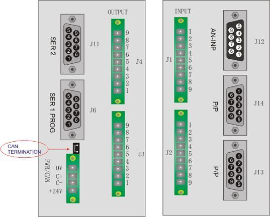
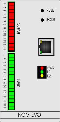
5 3 NGM EVO Connections UP DOWN FRONT 5

6 4 Connections Description 4.1 Power The NGMEVO requires two separate power supplies: Logical Power, PWR Digital Outputs Power, J3 e J4 To supply the digital outputs, see the relevant chapter 4.9 As regards the supply of the logic section, this is necessary for normal operation of the card Electrical Characteristics U.m. Min Standard Max DC IN Vdc Power (to 24Vdc) W 2,6 THE SYSTEM IS PROTECTED FROM POLARITY INVERSION WARNING DO NOT EXCEEDS THE MAXIMUM VOLTAGE VALUE ADMITTED BECAUSE THE CARD CAN BE DAMAGED 6

7 4.2 Serial Ports The serial ports on the NGMEVO allow communication with external devices to the control, PC-type, PLC and other. SER1-PRG: is normally used both for the download of the programs on the control, both for the debugging from a PC application. It is also the port to use for updating the firmware SER2: Can be used for communication with other devices, such as a PLC, inverters or other. CAN BE CONFIGURED RS485 MODE. For the electrical signal, the serial ports are in compliance with RS232/RS485. Use a CABLE WITH SHIELD for serial ports connections Connect the SHIELD to PIN 5 SER1 or SER2 to NGMEVO ports Generally the RS232 connection, uses a NULL MODEM cable (pin 2,3,5) CROSSOVER (with inversion on pin 2,3) Always check the external device that type of connection it accepts RS232 RS485 Normally the GND pin is not connect 7

8 4.2.1 Connections J6 SER1/PROG J11 SER2 WARNING DO NOT EXCEEDS THE MAXIMUM VOLTAGE VALUE ADMITTED BECAUSE THE CARD CAN BE DAMAGED 8

9 4.3 CAN BUS Port The port CAN BUS allows the communication of the card NGMEVO with type devices for motors drives, slave of various kinds, encoders, and more. Communication takes place via the CAN OPEN protocol, based on its specifications DS401 and DS402 as regards the objects and the modes supported. In terms of data exchange, the line complies with DS301. The port can be configured as master or slave depending on the firmware present. The port CAN-BUS meets the specifications of ISO V Connection CAN BUS Is possible insert the TERMINATOR RESISTOR, inserting the JUMPER above the power connector. WARNING If the NGMEVO board is configured as MASTER, insert always the TERMINATOR JUMPER If the NGMEVO is configured as SLAVE, insert the TERMINATOR JUMPER if the board is the last node in the CanBus. In another situations, remove the JUMPER WARNING USE THE CABLE FOR CANOPEN COMMUNICATION CanOpen Max PDO Number Normally the max PDO number managed by NGMEVO Canopen system, is 10. It is a total for PDO Rx and PDO Tx ex: 7 PDO Tx 3 PDO Rx 9

10 4.3.3 CanOpen Cable CONDUCTORS ELETTRIC RESISTANCE 22AWG: < 55,4 Ohm/Km 21AWG: < 43,6 Ohm/Km PAIR CAPACITY 50 pf/m IMPEDENCE 120 Ohm TRASMISSION SPEED-CABLE LENGTH Baud rate 1Mb Length Max 25 Mt Baud rate 800 Kb Length Max 50 Mt Baud rate 500 Kb Length Max 100 Mt Baud rate 250 Kb Length Max 250 Mt Baud rate 125Kb Length Max 500 Mt VOLTAGE EXERCISE 30 V 10


11 4.4 Ethernet Port The Ethernet port, allows the NGMEVO to communicate with other devices, llike PC and others. On data exchange level, it complies 10 BaseT and 100 BaseT standards. About protocols, it can be used in many ways: NGMEVO to PC communication, about on-line assistance. In this case it's used a PROMAX specific protocol; PLC and other devices communication, with ModBus TCP/IP protocol; Connections The on board connector, complies the RJ45 standard, It's recommended to use PC with Ethernet ports complies this standard. It's recommended to use cables length conformed the standard. The connection cable can be CROSSOVER or NORMAL The port is automatically adapted to cable type WARNING USE THE CABLE FOR ETHERNET COMMUNICATION WARNING WITH THE ETHERNET PORT, ISN T POSSIBLE TO UPLOAD FIRMAWARE OR VTB APPLICATION 11

12 4.5 Analog inputs The analog converter reads an input voltage from 0 to 10V or 4/20 ma with respect to GND. To get the full scale 12V or 24V, an external resistor must be inserted between the signal and card input. In any case, the value of the input voltage can exceed the full scale is not more than 0.2 V. The use of analog input, remove automatically a digital input (see the following table) Reference table for exclusion digital inputs Analog Input Configured Digital Input Removed Analog Inputs Connections J Input Resistance MIN TIPICA MAX VDC 25 Kῼ 72 Kῼ 4-20 Ma 175 ῼ External resistance for voltages other than 0-10V or 4-20Ma VIN Rext 0-12 V 63 Kῼ 0-24 V 424 Kῼ 12


13 4.5.4 Connection example 10 Kῼ WARNING DO NOT EXCEEDS 0,2 Volt THE MAXIMUM VALUE SELECTED THE ANALOG INPUT, CAN BE DAMAGED THE BOARD 4.6 Analog Output on NGMEVO The NGMEVO board, can be configure one analog output 0-10V Electric characteristics U.m. Min Max Analog Output Voltage Vdc 0 10 WARNING THIS CONFIGURATION, ELIMINATES THE DIGITAL OUTPUT 1 13
14 4.7 Channels STEP/DIR The board NGMEVO can use, up to four channels STEP / DIR for a total frequency of 400 Khz in position mode (125 Khz in interpolation mode). The outputs can be configured with OPEN COLLECTOR signals, or LINE DRIVE OPEN-COLLECTOR POWER LOAD STATE ON (voltage) FREQUENCY MAX 48 VDC 100 Ma continuativo 500 Ma picco MIN 0V MAX 1V MAX 30 Khz LINE DRIVE OUTPUT DIFFERENTIAL FREQUENCY MIN 2.2V MAX 3.3V specific TIA/EIA-422-B (RS422) MAX 400 Khz in position mode 125 Khz in interpolation mode specifics TIA/EIA-422-B (RS422) LOAD V Min V Typical 3,9 Kῼ 3,2 V 100 ῼ 2 2,6 V WARNING USE A CABLE WITH SHIELD FOR THE CONNECTIONS 14
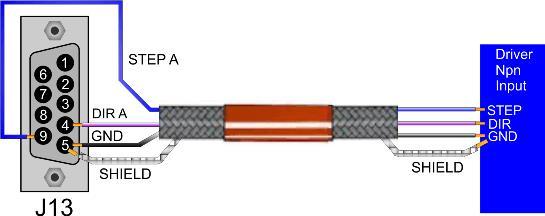
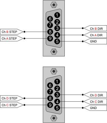
15 4.7.3 Connections OPEN COLLECTOR J13 /J14 J13 J14 J13 15

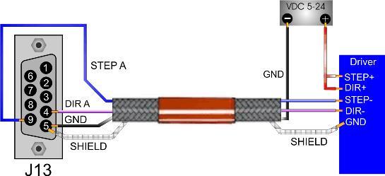
16 4.7.4 Connections LINE DRIVE J13 J14 16
17 4.8 Encoder Input The NGMEVO can use an internal input encoder Line Drive. When this option is enabled, the number of PULSE/DIR channels is TWO. This encoder input is normally used for HANDWHEEL FUNCTION It means that the frequency inputs is not to high Electric characteristics U.m. Min Soglia Max On voltage level Vdc 0 0,8 Off volatge level Vdc 4 12 R input Ω 6 Frequency KHz 32 * T0 PNP Index T0 NPN Index On level Vdc 2,5 2,2 7,7 Off level Vdc 0 1,5 On level Vdc 0 1,4 1 Off level Vdc 2 7,7 * If is used the PULSE/DIR channels, the frequency can be decreased 17

18 4.8.2 Example WARNING USE A CABLE WITH SHIELD FOR THE CONNECTIONS WARNING The Power for encoder MUST BE EXTERNAL 18
 OFF ms 2 (@ 24Vdc) Current ma 4 (10Vdc) 14 (@ 28Vdc) 4.9.")
19 4.9 Digital Inputs All these signals are PNP Type optically isolated. Therefore, to enable an input must bring a positive VDC (24 Vdc typical) on the desired channel refers to the common inputs Electric characteristics U.m. Min Standard Max State On Vdc State Off Vdc 0 4 Delay ON ms 3 (@ 24Vdc) OFF ms 2 (@ 24Vdc) Current ma 4 (10Vdc) 14 (@ 28Vdc) Connections J1/J2 WARNING DO NOT EXCEEDS THE VOLTAGE LEVEL ABOVE DESCRIBED 19


. 4.10.1 Electric characteristics U.m.")
20 4.10 Digital Outputs These outputs are optically isolated with respect to GND. In order to function should therefore feed them separately with a voltage of 24 Vdc. The load is driven by a transistor of the PNP type which when activated will provide a positive voltage equal to the voltage supply of the outputs. The outputs have a protection: REVERSE TENSION TEMPERATURE SHORT CIRCUIT On the card there is a protection diode so you can also directly drive inductive loads. In case of inductive loads with absorption greater than or equal to 0,5 A or when the cable connection between the load and board exceeds a length of 3 meters, you should put the protection diode also close to the load (diode type 1N4007 or similar) Electric characteristics U.m. Min Standard Max Note Power Vdc Load A 0,5 Continue (Tamb 25 ) Short Circuit Current A 0,7 1,7 Delay ON μs 100 OFF μs Connections J3/J4 WARNING DO NOT EXCEEDS THE VOLTAGE LEVEL ABOVE DESCRIBED THE DIGITAL OUTPUTS, ARE NOT PROTECTED BY OVERLOAD OR SHORT CIRCUIT 20
21 5 Programming 5.1 Manual Boot The board usually uses an automatic boot. In case, the automatic boot is not available, it is necessary to proceed in the following way: 1) Run the program NGPROG (if used VTB skip step 2 and 3) 2) Set the COM and the type of card NGMEVO 3) Load the application. SREC and press TRANSFER APPLICATION 4) Press the keys simultaneously within 15 seconds RESET AND BOOT on the board 5) Release the RESET button 5.2 Upload VTB application For upload VTB application, is possible use the following mode: The board NGMEVO is automatically in BOOT MODE (if is not available, see 5.1) when you use the BUTTON UPLOAD APPLICATION. The application is automatically RUN when the transfer is finish. 5.3 NGPROG The application was developed by Promax NGPROG to allow the update software and firmware of the new controls based on μp ColdFire Upload firmware 1) Press button FIRMWARE MANAGEMENT on NGProg 2) If you use UPDATE da File use the standard windows Browser for find the.srec file 2) If you use UPDATE da Server you must have a intenet active connection, NGPROG search in Promax server the new version of firmware 3) Select the serial port to PC and NGMEVO (or NGM13 if not present) board type 4) Start the upload firmware Upload VTB application 1) Select the NGMEVO (or NGM13 if not present) Board 2) Select the COM on PC 3) Selct the.srec file by button LOAD 4) Start the upload by button Upload Application 6 Status Led ST-1/L1 (Green led): Fast blink board in BOOT MODE blink1 sec application RUN ST-2/L2 (Yellow led): NO BLINK - No activity on RS232 or CAN SLAVE BLINK - activity on RS232 or CAN SLAVE PWR (Red led): Power On 21

22 7 NGMIO Connections The NGMIO board, is an expansion for NGMEVO local BUS: 16 Digital Inputs 14 Digital Outputs Can Be insert up to 4 expansions NGMIO for a total: 80 Digital Inputs 70 Digital Outputs The digital I/O are the same specifics to NGMEVO I/O, see Chapr. 4.8 and 4.9 FRONT Front Up UP DOWN Down 102 mm 21,50 mm 22

23 7.1 Connections NGMIO J1/J2 REFER TO CHAPTERS 4.8 AND 4.9 FOR CONNECTIONS AND WARNINGS 7.2 Connections NGMIO J3/J4 23

24 8 NGMsX Connections The NGMsX board, is an expansion for NGMEVO local BUS: 2 Channels STEP/DIR 500 Khz clock interpolation and position mode 2 Channels encoder Line Drive 500 Khz 2 Analog Outputs +/- 10 V 12 bit Can Be insert up to 3 expansions NGMsX Can be managed the following combinations for a NGMsX expansion: 2 Channels STEP/DIR 2 Channels STEP/DIR and 2 Analog Outputs 1 Channel STEP/DIR, 2 Analog Outputse 2 Channels Encoder 1 Channel STEP/DIR and 2 Channels Encoder FRONT UP Front Up Down DOWN 102 mm 21,50 mm 24


25 8.1 Channels STEP/DIR on NGMsX Expansion The NGMsX board can use 2 channels STEP/DIR up to 500 Khz clock for single channel The outputs are type LINE DRIVE 5V OUPUT CLOCK MIN 3V MAX 5V MAX 500 Khz J21 J21 WARNING USE A CABLE WITH SHIELD FOR THE CONNECTIONS 25
 must be connected with a shielded cable, to prevents electromagnetic interference.")
26 8.2 Channels ENCODER on NGMsX Expansion The NGMsX can use TWO channels ENCODER LINE DRIVE up to 500 Khz for channel. The encoder (or optical line) must be connected with a shielded cable, to prevents electromagnetic interference. It's also recommended to have separated cable for each encoder and put far away the connection by interferences sources (inverters,high voltage cable, AC motors, ecc.). NGIO is ready to use LINE-DRIVE encoders, also supplies the +5Vdc source voltage. It can't be used with PUSH- PULL or OPEN-COLLECTOR encoders. In case of motor-drives encoder simulation, is not necessary to connect the Vdc supply, but only the GND Electric characteristics U.m. Min Soglia Max On voltage level Vdc 0 0,8 Off volatge level Vdc 4 12 R input Ω 6 Frequency KHz 500 T0 PNP Index T0 NPN Index On level Vdc 2,5 2,2 7,7 Off level Vdc 0 1,5 On level Vdc 0 1,4 1 Off level Vdc 2 7, Electric characteristics +5vdc output encoder supply Channel Min Max Output Cuurent Ch1 J22 4,75 Vdc 5,25 Vdc 100 Ma Ch2 J23 4,75 Vdc 5,25 Vdc 100 Ma 26


27 8.2.3 Example J22/J23 WARNING USE A CABLE WITH SHIELD FOR THE CONNECTIONS 27

28 8.3 Analog Outputs on NGMsX Expansion The NGMsX board can use TWO analog outputs +/-10 V 12 bit and TWO RELE' CONTACTS Electric characteristics U.m. Min Standard Max Analog Output Output voltage Vdc -10 9,995 Output impedence Ω Relè Conctat Voltage Vdc 35 Current A 1 WARNING USE A CABLE WITH SHIELD FOR THE CONNECTIONS 28
29 9 Dimensions N=expansions number NGMIO or NGMsx 29
30 10 Notes on the CE legislation NGMEVO We have two directives about electronic devices, regarding the NGMEVO : the 2006/42/CE (machine directive) about safety use of the devices and 2004/108/CE about electromagnetic compatibility. About the first (machine directive) electric/electronic devices, must complies the "low voltage" directive (2006/95/CE) but it can be applied on devices supplied at Vac or Vdc. NGMEVO works at a voltage of 24Vdc (thus Intrinsically safe ), so it belongs to "very low voltage" devices (class 0 legislation CEI 11.1), on which it isn't no legislation about. On electromagnetic compatibility, regarding the 2004/108/CE norm, this device can be classified as a "finished appliance". Due to the fact that the NGMEVO will be normally integrated inside a complex electromechanics system, the machine electric board, by a manufacturer in an industrial ambit and not by a final customer, it haven t any certification duty. PROMAX however, can institute some specific measure as a pre-compliance, in case of particular demands of costumers, regarding the device electromagnetic characterization. For example, can be made some measure under the CEI EN norm (2007 generic norms residential, commercial and light industrial ambient immunity) or CEI EN (2007 generic norms - residential, commercial and light industrial ambient emission) 30
31 Index Features Identification Code NGM EVO NGM EVO Connections Connections Description Power Electrical Characteristics Serial Ports Connections J6 SER1/PROG J11 SER CAN BUS Port Connection CAN BUS CanOpen Max PDO Number CanOpen Cable CONDUCTORS ELETTRIC RESISTANCE Ethernet Port Connections Analog inputs Analog Inputs Connections J Input Resistance External resistance for voltages other than 0-10V or 4-20Ma Connection example Analog Output on NGMEVO Electric characteristics Channels STEP/DIR OPEN-COLLECTOR LINE DRIVE Connections OPEN COLLECTOR J13 /J Connections LINE DRIVE Encoder Input Electric characteristics Example Digital Inputs Electric characteristics Connections J1/J
32 4.10 Digital Outputs Electric characteristics Connections J3/J Programming Manual Boot Upload VTB application NGPROG Upload firmware Upload VTB application Status Led NGMIO Connections Connections NGMIO J1/J Connections NGMIO J3/J NGMsX Connections Channels STEP/DIR on NGMsX Expansion Channels ENCODER on NGMsX Expansion Electric characteristics Electric characteristics +5vdc output encoder supply Example Analog Outputs on NGMsX Expansion Electric characteristics Dimensions Notes on the CE legislation
PLC-K506 Series FEATURES DESCRIPTION FEATURES
 FEATURES Two High Speed Counters Two Pulse Train Outputs Two Pulse Width Modulation Outputs Inputs 10 Outputs 1 RS232 Port 2 RS485 Ports Supports Modbus RTU Protocol Communicate With Up to 32 Devices DESCRIPTION
PROMUX Distributed MODBUS I/O Modules Catalog and Design Guide
 PROMUX Distributed MODBUS I/O Modules Catalog and Design Guide 14/11/2006 V10 P.O.Box 24 Stanfield 3613 SOUTH AFRICA Tel: +27 (031) 7028033 Fax: +27 (031) 7028041 Email: proconel@proconel.com Web: www.proconel.com
Data Acquisition Modules/ Distributed IO Modules
 User Manual Data Acquisition Modules/ Distributed IO Modules Future Design Controls, Inc. 7524 West 98 th Place / P.O. Box 1196 Bridgeview, IL 60455 888.751.5444 - Office: 888.307.8014 - Fax 866.342.5332
KNC-PLC-K506 Series FEATURES DESCRIPTION FEATURES
 FEATURES Two High Speed Counters Two Pulse Train Outputs Two Pulse Width Modulation Outputs Inputs 10 Outputs 1 RS232 Port 2 RS485 Ports Supports Modbus RTU Protocol Communicate with up to 32 devices DESCRIPTION
PROMUX Distributed MODBUS I/O Modules Catalog and Design Guide
 PROMUX Distributed MODBUS I/O Modules Catalog and Design Guide 12/03/2012 V11.0 P.O.Box 164 Seven Hills 1730 NSW AUSTRALIA Tel: +61 2 96248376 Fax: +61 2 9620 8709 Email: proconel@proconel.com Web: www.proconel.com
maxon document number:
 maxon document number: 791272-04 1 Table of contents... 2 2 Table of figures... 3 3 Introduction... 4 4 How to use this guide... 4 5 Safety Instructions... 5 6 Performance Data... 6 6.1 Motor data... 6
SilverMax Datasheet. QuickSilver Controls, Inc. NEMA 23 Servomotors.
 SilverMax Datasheet NEMA 23 Servomotors QuickSilver Controls, Inc. www.quicksilvercontrols.com SilverMax Datasheet - NEMA 23 Servomotors 23 Frame Sizes: 23-3, 23-5, 23H-1, 23H-3, 23H-5 / Series: E, E3,
8V General information. 2 Order data 8V
 8V05.00-8V05.00- General information Modular mechanical design using plug-in modules Integrated line filter Integrated braking resistor All connections are made using plug-in connectors Integrated electronic
8V General information. 2 Order data 8V
 8V80.00-8V80.00- General information Modular mechanical design using plug-in modules Integrated line filter Integrated or optional external braking resistor All connections are made using plug-in connectors
Assembly Instructions
 Assembly Instructions optocontrol 2520 Functions Edge measurement with the shadow principle (Edge low-high; edge high-low) Measurement of diameter-, width-, gap incl. center axis Counting of edges or segments,
Modbus communication module for TCX2: AEX-MOD
 Modbus communication module for TCX2: Communication Specification TCX2 is factory installed in TCX2 series controllers with -MOD suffix, and is also available separately upon request for customer installation
LCC-10 Product manual
 LCC-10 Product manual Rev 1.0 Jan 2011 LCC-10 Product manual Copyright and trademarks Copyright 2010 INGENIA-CAT, S.L. / SMAC Corporation Scope This document applies to i116 motion controller in its hardware
Z-10-D-IN. RS485 Modbus Module 10 Digital Inputs
 S SENECA Z-PC Line EN Installation Manual Contents: - General specifications - Technical specifications - Installation rules - Electrical connections - Modbus connection rules - DIP-switches settings -
W(G)S3.1 Position Sensor with Analog or A/D converted synchronous serial output
S3.1 Position Sensor with Analog or A/D converted synchronous serial output") W(G)S3.1 Position Sensor with Analog or A/D converted synchronous serial output Position and Velocity Sensor for Long Ranges Protection Class IP50 Measurement Range: 0... 10000 mm to 0... 15000 mm 0...
W(G)S3.1 Position Sensor with Analog or A/D converted synchronous serial output Position and Velocity Sensor for Long Ranges Protection Class IP50 Measurement Range: 0... 10000 mm to 0... 15000 mm 0...
IF30. User's manual. Description. Table of contents IF30
 User's manual IF30 Description IF30 is an encoder interface unit designed to convert the output signals delivered by so-called sine-cosine-encoders and similar measuring systems (devices which deliver
Protection Class (IEC 529)
") (W)GS2 Velocity Sensor with Analog or A/D converted synchronous serial output Specifications Velocity Sensor with Position Option Class IP50 Measurement Range: 0... 1500 mm to 0... 2500 mm 0... 59.06 in
(W)GS2 Velocity Sensor with Analog or A/D converted synchronous serial output Specifications Velocity Sensor with Position Option Class IP50 Measurement Range: 0... 1500 mm to 0... 2500 mm 0... 59.06 in
Jaguar Motor Controller (Stellaris Brushed DC Motor Control Module with CAN)
") Jaguar Motor Controller (Stellaris Brushed DC Motor Control Module with CAN) 217-3367 Ordering Information Product Number Description 217-3367 Stellaris Brushed DC Motor Control Module with CAN (217-3367)
Jaguar Motor Controller (Stellaris Brushed DC Motor Control Module with CAN) 217-3367 Ordering Information Product Number Description 217-3367 Stellaris Brushed DC Motor Control Module with CAN (217-3367)
ES86 Series Closed-loop Stepper Drive + Motor System (Drive+ Motor/Encoder)
") ES86 Series Closed-loop Stepper Drive + Motor System (Drive+ Motor/Encoder) Traditional stepper motor drive systems operate open loop providing position control without feedback. However, because of this,
ES86 Series Closed-loop Stepper Drive + Motor System (Drive+ Motor/Encoder) Traditional stepper motor drive systems operate open loop providing position control without feedback. However, because of this,
Selection guide. Communication accessories. Communication accessory selection guide. Characteristics
 Communication accessories Selection guide There are 2 types of Sepam communication accessories: b communication interfaces, which are essential for connecting Sepam to the communication network b converters
NetBiter I/O Extender 4RO 6RTD 8DIO - DAIO User Manual Revision 1.00
 NetBiter I/O Extender 4RO 6RTD 8DIO DAIO User Manual Revision 1.00 IntelliCom Innovation AB Linjegatan 3D SE302 50 Halmstad SWEDEN Phone +46 35 18 21 70 Fax +46 35 18 21 99 email info@intellicom.se www
EP-5111, EP-5112, EP-5212, EP-5261, EP-5311, EP-5422, EP-5442
 October 2017 RSTI-EP Slice I/O Specialty Modules EP-5111, EP-5112, EP-5212, EP-5261, EP-5311, EP-5422, EP-5442 Module Status LED Channel Status LED GE provides several RSTi-EP specialty modules, which
This data sheet is only valid in association with the IL SYS INST UM E user manual.
 Inline counter terminal, version for extreme conditions, 1 counter input, 1 control input, 1 output, 24 V DC, 500 ma Data sheet 106148_en_03 PHOENIX CONTACT 2015-11-04 1 Description The terminal is designed
ES86 Series Closed-loop Stepper Drive + Motor System (Drive+ Motor/Encoder)
") ES86 Series Closed-loop Stepper Drive + Motor System (Drive+ Motor/Encoder) Traditional stepper motor drive systems operate open loop providing position control without feedback. However, because of this,
ES86 Series Closed-loop Stepper Drive + Motor System (Drive+ Motor/Encoder) Traditional stepper motor drive systems operate open loop providing position control without feedback. However, because of this,
Brushed DC Motor Control. Module with CAN (MDL-BDC24)
") Stellaris Brushed DC Motor Control Module with CAN (MDL-BDC24) Ordering Information Product No. MDL-BDC24 RDK-BDC24 Description Stellaris Brushed DC Motor Control Module with CAN (MDL-BDC24) for Single-Unit
Stellaris Brushed DC Motor Control Module with CAN (MDL-BDC24) Ordering Information Product No. MDL-BDC24 RDK-BDC24 Description Stellaris Brushed DC Motor Control Module with CAN (MDL-BDC24) for Single-Unit
The wireless alternative to expensive cabling...
 The wireless alternative to expensive cabling... ELPRO 105U ISO 9001 Certified New Products... New Solutions The ELPRO 105 range of telemetry modules provide remote monitoring and control by radio or twisted-pair
PAM & SAM System User s Manual
 PAM & SAM System User s Manual Part 5 - SAM Drive Technical Information Ordering Number: 9032 011 985 Issue November 14, 2000 This version replaces all previous versions of this document. It also replaces
DSEM640. DSEControl PROGRAMMABLE CONTROLLER FOR USE IN VEHICLES AND OFF-HIGHWAY MACHINERY
 PROGRAMMABLE CONTROLLER FOR USE IN VEHICLES AND OFF-HIGHWAY MACHINERY OVERVIEW DC SUPPLY 8 V DC to 36 V DC CURRENT CONSUMPTION OPERATING CURRENT < 300 ma at 24 V without external loads TOTAL INPUTS/OUTPUTS
The wireless alternative to expensive cabling...
 The wireless alternative to expensive cabling... ELPRO 105U Wireless Solutions for Process Applications New Products... New Solutions The ELPRO 105U range of wireless I/O provides a low cost alternative
RSMFX-2R MULTIFUNCTIONAL
 Mounting and operating instructions Table of contents SAFETY AND PRECAUTIONS 3 PRODUCT DESCRIPTION 4 ARTICLE CODES 4 INTENDED AREA OF USE 4 TECHNICAL DATA 4 STANDARDS 4 OPERATIONAL DIAGRAMS 5 WIRING AND
7I33 / 7I33TA MANUAL Quad analog servo amp interface
 7I33 / 7I33TA MANUAL Quad analog servo amp interface V1.9 This page intentionally almost blank Table of Contents GENERAL.......................................................... 1 DESCRIPTION.................................................
VFSC9 ELECTRONIC SPEED CONTROLLER. Mounting and operating instructions
 ELECTRONIC SPEED CONTROLLER Mounting and operating instructions Table of contents SAFETY AND PRECAUTIONS 3 PRODUCT DESCRIPTION 4 ARTICLE CODES 4 INTENDED AREA OF USE 4 TECHNICAL DATA 4 STANDARDS 5 WIRING
Ocean Controls KT-5221 Modbus IO Module
 Ocean Controls Modbus IO Module 8 Relay Outputs 4 Opto-Isolated Inputs 2 Analog Inputs (10 bit) 1 PWM Output (10 bit) 4 Input Counters Connections via Pluggable Screw Terminals 0-5V or 0-20mA Analog Inputs,
B850 Boiler House Energy Monitor
 Local regulations may restrict the use of this product to below the conditions quoted. In the interests of development and improvement of the product, we reserve the right to change the specification without
D SERIES LM16. COMPACT DRIVE V/f and SLV CONTROL. LM16 COMPACT DRIVE V/f and SLV CONTROL
 D SERIES LM16 COMPACT DRIVE V/f and SLV CONTROL LM16 COMPACT DRIVE V/f and SLV CONTROL 1 2 SERIES 1 2 page 4 page 6 Introduction Fields of application 3 page 7 4 page 8 Designation Product offer 5 6 page
The wireless alternative to expensive cabling...
 The wireless alternative to expensive cabling... ELPRO 905U Wireless Solutions for Process Applications New Products... New Solutions The ELPRO 905U range of telemetry modules provide remote monitoring
FC Series Signal Conditioners
 FC Series Signal Conditioners FC-33 DC Selectable Signal Conditioner with 3-way isolation Field configurable input and output ranges of 0-5V, 0-10 V, 0-20 ma and 4-20 ma with 1500 VDC isolation between
AIO and DIO PFXLM4B01DAK:Sink Output Type PFXLM401DAC:Source Output Type Virtual Resolution (pixels)
") Model:PFXLM4B01DDK PFXLM4B01DDC PFXLM4B01DAK PFXLM4B01DAC LT4000M Rear module Model Name Indication PFXLM4B01 D * * (1) (2) (3) (4) Notice to our valued customers who use LT4000M series (analog model)
Model:PFXLM4B01DDK PFXLM4B01DDC PFXLM4B01DAK PFXLM4B01DAC LT4000M Rear module Model Name Indication PFXLM4B01 D * * (1) (2) (3) (4) Notice to our valued customers who use LT4000M series (analog model)
I-2533CS series User Manual
 I-2533CS series User Manual Version 1.0.0, Sep. 2013 Service and usage information for I 2533CS / I 2533CS 60 / I 2533CS A / I 2533CS B I-2533CS series CAN to Single Mode Fiber Bridge User Manual (version
3DM phase Digital Stepper Drive
 3DM2283 3-phase Digital Stepper Drive 150-220VAC, 0.5-8.2A peak, Auto-configuration, Low Noise Anti-Resonance provides optimal torque and nulls mid-range instability Motor auto-identification and parameter
The wireless alternative to expensive cabling...
 The wireless alternative to expensive cabling... ELPRO 905U Wireless Solutions for Process Applications New Products... New Solutions The ELPRO 905U range of wireless I/O provides a low cost alternative
XIOC technology and networking modules
 / XIO XIO digitale and analog input/output modules XIO technology and networking modules XIO the compact I/O and much more XIO are local expansion modules for direct connection to all Xontrol controllers.
ES86 Series Closed-loop Stepper Drive + Motor System (ES-D808 Drive+ Motor/Encoder)
") ES86 Series Closed-loop Stepper Drive + Motor System (ES-D808 Drive+ Motor/Encoder) Traditional stepper motor drive systems operate open loop providing position control without feedback. However, because
ES86 Series Closed-loop Stepper Drive + Motor System (ES-D808 Drive+ Motor/Encoder) Traditional stepper motor drive systems operate open loop providing position control without feedback. However, because
Specifications.
 is a 7 capacitive touch display designed for use with PanelPilotACE Design Studio, a free drag-and-drop style software package for rapid development of advanced user interfaces and panel meters. The is
TECHNICAL DATASHEET #TDAX ISOLATED DUAL CHANNEL UNIVERSAL SIGNAL CONVERTER
 Preliminary TECHNICAL DATASHEET TDAX130540 ISOLATED DUAL CHANNEL UNIVERSAL SIGNAL CONVERTER 2 Analog (Bipolar), Resistive, Digital, Frequency (RPM) or PWM Signal Inputs Encoder Input Magnetic Pick Up Input
Cyclops User s Manual
 Cyclops User s Manual Revision 5.x.x March 14, 2017 Contents Background... 1 Interface... 1 Normal Operation... 1 Controller Input Type... 1 Communication... 2 Sensitivity... 3 Operating Modes... 3 Normal...
Protection class. Male 8 pin socket M12 (ADCANOP: 5 pin socket)
") WS10SG Analog, SSI or CANopen Output Very compact sensor for industrial applications Protection class IP65 Measurement range 0... 100 mm to 0... 1250 mm Analog output or A/D converted synchronous serial
WS10SG Analog, SSI or CANopen Output Very compact sensor for industrial applications Protection class IP65 Measurement range 0... 100 mm to 0... 1250 mm Analog output or A/D converted synchronous serial
AUR.EL RTX-MID-868-OOK DESCRIPTION. MECHANICAL DIMENSIONS and PIN-OUT. Absolute maximum values
 DESCRIPTION RTX-MID-868 is RF digital transceiver working at 868,3MHz with FSK and OOK modulation. The main features are: 10 mw Maximum of effective irradiated power, - 108 dbm of sensitivity in FSK and
User Manual. Data Acquisition Modules/ Distributed IO Modules
 User Manual Data Acquisition Modules/ Distributed IO Modules UMIOE Rev 5.0, 10/2009 COPYRIGHT NOTICE This manual is a publication of Brainchild Electronics Co.. Ltd. and is provided for use by its customers
CAN-IO Custom IO remote module
 CAN-IO Custom IO remote module Main characteristics High customization Integrate different types of inputs/ outputs Up to 40 total channels DIN rail mount or plate Main applications Climatic chambers Autoclaves
UniStream Built-in. Technical Specifications US7-B5-RA28, US7-B10-RA28 US7-B5-TA30, US7-B10-TA30
 UniStream Built-in Technical Specifications US5-B5-RA28, US5-B10-RA28 US5-B5-TA30, US5-B10-TA30 US7-B5-RA28, US7-B10-RA28 US7-B5-TA30, US7-B10-TA30 Unitronics UniStream Built-in series are PLC+HMI All-in-One
There are many important factors when trying to achieve good, reliable communications between 2 devices.
 APPLICATION NOTE THIS INFORMATION PROVIDED BY AUTOMATIONDIRECT.COM TECHNICAL SUPPORT These documents are provided by our technical support department to assist others. We do not guarantee that the data
905U Wireless. New Products... New Solutions. The wireless alternative to expensive cabling... Simple but Reliable. Easy to Use
 Wireless New Products... New Solutions The range of telemetry modules provide remote monitoring and control by radio or twisted-pair wire, over short or long distances. Transducer signals connected at
Analog Servo Drive 25A20DD
 Description Power Range NOTE: This product has been replaced by the AxCent family of servo drives. Please visit our website at www.a-m-c.com or contact us for replacement model information and retrofit
Electronic Control Automotive for Proportional Valves 4 Solenoid
 The command REP-A400 was designed to control up to 4 valves Proportional valves open loop (is those who do not have the transducer positioning inside) or feedback. The REP-A400 is a microcontroller device
Data sheet CPU 314ST/DPM (314-6CF02)
") Data sheet CPU 314ST/DPM (314-6CF02) Technical data Order no. Type 314-6CF02 CPU 314ST/DPM General information Note - Features SPEED-Bus SPEED7 technology, SPEED-Bus 8 x DI, 8 x DIO, 4 x AI, 2 x AO, 1
Data sheet CPU 314ST/DPM (314-6CF02) Technical data Order no. Type 314-6CF02 CPU 314ST/DPM General information Note - Features SPEED-Bus SPEED7 technology, SPEED-Bus 8 x DI, 8 x DIO, 4 x AI, 2 x AO, 1
Data sheet VIPA CPU 314SC DPM (314-6CG23)
") Data sheet VIPA CPU 314SC DPM (314-6CG23) Technical data Order no. Type 314-6CG23 VIPA CPU 314SC DPM General information Note - Features Powered by SPEED7 Work memory [KB]: 512...2.048 Onboard 24x DI /
Data sheet VIPA CPU 314SC DPM (314-6CG23) Technical data Order no. Type 314-6CG23 VIPA CPU 314SC DPM General information Note - Features Powered by SPEED7 Work memory [KB]: 512...2.048 Onboard 24x DI /
FOSTCDR. Industrial Serial to Multimode Fiber Optic Converter PRODUCT INFORMATION B&B ELECTRONICS. Specifications Serial Technology
 FOSTCDR pn 8684R1 FOSTCDR-0812ds page 1/5 Industrial Serial to Multimode Fiber Optic Converter Data Rates up to 115.2 kbps 2.5 Mile (4 km) Range 10 to 30 VDC Input Voltage Wide Operating Temperature 2000V
MPR kHz Reader
 MPR-5005 Page 1 Doc# 041326 MPR-5005 125kHz Reader Installation & Operation Manual - 041326 MPR-5005 Page 2 Doc# 041326 COPYRIGHT ACKNOWLEDGEMENTS The contents of this document are the property of Applied
7I33/7I33T MANUAL Quad analog servo amp interface
 7I33/7I33T MANUAL Quad analog servo amp interface V1.4 This page intentionally almost blank Table of Contents GENERAL.......................................................... 1 DESCRIPTION.................................................
Data sheet CPU 313SC (313-5BF13)
") Data sheet CPU 313SC (313-5BF13) Technical data Order no. Type 313-5BF13 CPU 313SC General information Note - Features SPEED-Bus - SPEED7 technology 24 x DI, 16 x DO, 4 x AI, 2 x AO, 1 x AI Pt100 128 kb
Data sheet CPU 313SC (313-5BF13) Technical data Order no. Type 313-5BF13 CPU 313SC General information Note - Features SPEED-Bus - SPEED7 technology 24 x DI, 16 x DO, 4 x AI, 2 x AO, 1 x AI Pt100 128 kb
Power quality Harmonics up to 40th harmonic Rotary field components Distortion factor THD-U / THD-I
 Memory 256 MB Alarm management Residual current measurement Homepage Ethernet-Modbus gateway BACnet (optional) UMG 96 RM-E Power analyser with Ethernet and RCM Communication Modbus (RTU, TCP, Gateway)
OptiLogic Series. Input/Output Modules. Optimal Automation for Industry. Optimation, Inc. (256)
") Input/Output Modules Optimal Automation for Industry Optimation, Inc. ()-00 WARNING Thank you for purchasing industrial control products from Optimation, Inc. We want your new system to operate safely.
Input/Output Modules Optimal Automation for Industry Optimation, Inc. ()-00 WARNING Thank you for purchasing industrial control products from Optimation, Inc. We want your new system to operate safely.
PROFIBUS HUB REPEATER
 USER S MANUAL PROFIBUS HUB REPEATER RHP303 R H P 3 0 3 M E smar www.smar.com Specifications and information are subject to change without notice. Up-to-date address information is available on our website.
KNC-SRV-FD423 Series Servo Driver
 FEATURES Input Voltage Range From 180-264VAC 400-750 Watt Power Range Position, Speed, and Torque Control RS232, RS485 and CAN Requires Single-Loop 17-Bit Magnetic Encoder, Single Lap 20-Bit Communication
SKIM USER S GUIDE SMART KAN INTERFACE MODULE 2 & 8 I/O
 SKIM USER S GUIDE SMART KAN INTERFACE MODULE 2 & 8 I/O Kongsberg Automotive: Christopher Martin Road Basildon, Essex England SS143ES Tel: +44(0)1268 522861 Fax: +44(0)1268 282994 90, 28e Rue Grand-Mere
PHOENIX CONTACT - 03/2007
 Inline Function Terminal for Pulse Width Modulation and Frequency Modulation N AUTOMATIONWORX Data Sheet 6920_en_01 1 Description PHOENIX CONTACT - 03/2007 $ ' ) The terminal is designed for use within
B850 Boiler House Energy Monitor
 Local regulations may restrict the use of this product to below the conditions quoted. In the interests of development and improvement of the product, we reserve the right to change the specification without
Inverter Drive /Vector Drive Motors & Controls
 H2 Inverter/ Encoderless Vector Inverter Drive /Vector Drive & Controls 3/4 thru 50 180-264 VAC 3 Phase - 50/60 Hz 3/4 thru 60 340-528 VAC 3 Phase - 50/60 Hz 3/4 thru 60 515-660 VAC 3 Phase - 60 Hz HVAC
LAUREL ELECTRONICS, INC.
 LAUREL ELECTRONICS, INC. Laureate True RMS AC Voltage & Current Meter with 1 Cycle Update at 50/60 Hz Features True AC or AC plus DC RMS measurement with crest factor of 3.0 at FS Fast response: reading
3V DUAL MODE TRANSCEIVER 434 MHz BAND Product Code:
 3V DUAL MODE TRANSCEIVER 434 MHz BAND Product Code: 32001269 Rev. 1.6 PRODUCT SUMMARY: Dual-mode transceiver operating in the 434 MHz ISM band with extremely compact dimensions. The module operates as
Data sheet CPU 013C (013-CCF0R00)
") Data sheet CPU 013C (013-CCF0R00) Technical data Order no. 013-CCF0R00 Type CPU 013C Module ID - General information Note - Features SPEED7 technology 16 x DI, 12 x DO, 2 x AI, from which are 4 input channels
Data sheet CPU 013C (013-CCF0R00) Technical data Order no. 013-CCF0R00 Type CPU 013C Module ID - General information Note - Features SPEED7 technology 16 x DI, 12 x DO, 2 x AI, from which are 4 input channels
D SERIES EM16 IP 20 / NEMA 1 & IP 66 / NEMA 4X COMPACT VECTOR CONTROL DRIVE EM 16 COMPACT VECTOR CONTROL DRIVE
 D SERIES EM16 IP 20 / NEMA 1 & IP 66 / NEMA 4X COMPACT VECTOR CONTROL DRIVE EM 16 COMPACT VECTOR CONTROL DRIVE 1 2 SERIES 1 2 pag. 4 pag. 5 Applications Model identification 3 pag. 5 4 pag. 6 Capacity
TECHNICAL DATASHEET #TDAX Universal Signal Inputs CAN Controller V, ma, Digital, PWM, Hz/RPM, Counter Inputs CANopen P/N: AX030121
 TECHNICAL DATASHEET #TDAX030121 10 Universal Signal Inputs CAN Controller V, ma, Digital, PWM, Hz/RPM, Counter Inputs CANopen Features: 10 user selectable signal inputs: o 0-5 V o 0-10 V o 0-20 ma o 4-20
PFXLM4B01 D * * (1) (2) (3) (4)
 (2) (3) (4)") Model:PFXLM4B01DDK PFXLM4B01DDC PFXLM4B01DAK PFXLM4B01DAC LT4000M Rear module Model Name Indication PFXLM4B01 D * * (1) (2) (3) (4) Notice to our valued customers who use LT4000M series (analog model)
Model:PFXLM4B01DDK PFXLM4B01DDC PFXLM4B01DAK PFXLM4B01DAC LT4000M Rear module Model Name Indication PFXLM4B01 D * * (1) (2) (3) (4) Notice to our valued customers who use LT4000M series (analog model)
MULTIFUNCTION GRAPHICAL UNIT MGU 800
 MULTIFUNCTION GRAPHICAL UNIT MGU 800 For display, recording and evaluation of process instruments signals (level, temperature, pressure, etc.) 3.5" TFT display, multi-language menu Variety of possible
CFO900 Series. User Manual. Audio/Data/Current Loop Mux/Demux CSX111, CSX123 & CSX222. CFO CSX series user manual, , rev003
 CFO900 Series User Manual Audio/Data/Current Loop Mux/Demux CSX, CSX23 & CSX222 CFO CSX series user manual, 59300048, rev003 Contents The CSX Series Multiplexer Introduction... Introduction... Frame installation...2
Absolute Rotary Encoder
 Absolute Rotary Encoder Use the Tough (Rated IP64 for Degree of Protection) Combined with a PLC or Cam Positioner for Optimum Control and Ease-of-Use Incorporates a sealed bearing, meeting IP64 for durability
ECB-103 BACnet B-ASC 10-Point Programmable Controllers
 D a t a s h e e t BACnet B-ASC 10-Point Programmable Controllers Overview The is a microprocessor-based programmable controller designed to control terminal units such as fan coil unit, heat pump unit,
POSICHRON position sensor in a stainless steel pressure tube. Protection class IP68/IP69K
 Round Profile Housing with Analog POSICHRON position sensor in a stainless steel pressure tube Protection class IP68/IP69K Underwater applications, permanent pressure-proof up to 15 bar Measurement range
ASP-X2. Accelus Panel. Control Modes Current (torque, force)
") 2-AXIS DIGITAL SERVOAMPLIFIER for BRUSHLESS/BRUSH MOTORS Control Modes Current (torque, force) Opto-Isolated Command Interface (per channel) ±0V Current control input Enable input Buffered encoder outputs
2-AXIS DIGITAL SERVOAMPLIFIER for BRUSHLESS/BRUSH MOTORS Control Modes Current (torque, force) Opto-Isolated Command Interface (per channel) ±0V Current control input Enable input Buffered encoder outputs
PM50. Technical Data TECHNOSOFT. DSP Motion Solutions. Power Module for DC, Brushless DC and AC Motors. Version 3.0. PM50 v3.0.
 Version 3.0 PM50 TECHNOSOFT DSP Motion Solutions Power Module for DC, Brushless DC and AC Motors Technical Data Technosoft 2001 Technosoft 2001 1-1 PM50 v3.0 Technical Data TECHNOSOFT DSP Motion Solutions
UNICOM 2500 UNICOM Installation Operation Programming. Universal Communication Converter
 User Manual UNICOM 2500 Installation Operation Programming Universal Communication Converter UNICOM 2500 Electro Industries/GaugeTech 1800 Shames Drive Westbury, New York 11590 Tel 516.334.0870 Fax 516.338.4741
Expansion port CNT USER S GUIDE
 OBSAH Expansion port CNT USER S GUIDE USED SYMBOLS Used symbols Danger important notice, which may have an influence on the user s safety or the function of the device. Attention notice on possible problems,
UniStream 5" Technical Specifications US5-B5-RA28, US5-B10-RA28
 UniStream 5" Technical Specifications US5-B5-RA28, US5-B10-RA28 Unitronics UniStream 5" are PLC+HMI All-in-One programmable controllers that comprise built-in HMI and built-in I/Os. The series is available
em4 em4 alert em4 alert 2G
 em4 em4 alert em4 alert 2G Connect your equipment to the GPRS 2G network and get alerted by SMS or email Control your application by SMS Receive data reports by SMS or datalogs by email or FTP in.csv (Excel)
LXM32CD18N4 motion servo drive - Lexium 32 - three-phase supply voltage 208/480V kw
 Product data sheet Characteristics LXM32CD18N4 motion servo drive - Lexium 32 - three-phase supply voltage 208/480V - 1.8 kw Main Range of product Lexium 32 Product or component type Device short name
Serial Communications RS232, RS485, RS422
 Technical Brief AN236 Technical Brief AN236Rev A Serial Communications RS232, RS485, RS422 By John Sonnenberg S u m m a r y Electronic communications is all about interlinking circuits (processors or other
CONTROL MICROSYSTEMS SCADAWave Radio Transceiver. Hardware Manual
 5908 SCADAWave Radio Transceiver Hardware Manual CONTROL MICROSYSTEMS SCADA products... for the distance 48 Steacie Drive Telephone: 613-591-1943 Kanata, Ontario Facsimile: 613-591-1022 K2K 2A9 Technical
Design Characteristics. FlexDrive II. Series
 AC AC DC DC FlexDrive II Series Design Characteristics Brushless AC Servo Baldor s FlexDrive II series are designed to provide reliable and durable operation. Options are available to operate either resolver
Characteristics and functioning
 Characteristics and functioning /25 ENOD4 PRODUCT RANGE:... 4. General presentation:... 4.2 enodview software tool... 4.3 Versions and options:... 4.3. Versions:...4.3.2 Options :...4.4 Dimensions:...
Logosol AC/DC Intelligent Servo Drive for Coordinated Control LS-174WP
 Features Motors supported: - Panasonic A and S series - Brushless 60/120 commutated - Brush-commutated (DC) motors Up to 20A peak, 12A continuous output current 12 to 90VDC power supply Separate motor
ADA-1028L. User manual ADA-1028L. RS232 to Current Loop 2-wire CLO Converter. 1 io_ada-1028l_v.1.10_en. Copyright CEL-MAR sp.j.
 User manual ADA-1028L to Current Loop 2-wire Converter Copyright 2001-2017 CEL-MAR sp.j. 1 io_ada-1028l_v.1.10_en Contents 1. GENERAL INFORMATION... 3 1.1. WARRANTED INFORMATION... 3 1.2. GENERAL CONDITIONS
LXM32AD18M2 motion servo drive - Lexium 32 - single phase supply voltage 115/230V - 0.5/1kW
 Product data sheet Characteristics LXM32AD18M2 motion servo drive - Lexium 32 - single phase supply voltage 115/230V - 0.5/1kW Main Range of product Lexium 32 Product or component type Device short name
DigiFlex Performance Servo Drive DPQNNIE-030A800
 DigiFlex Performance Servo Drive DPQNNE-030A800 Description Power Range The DigiFlex Performance (DP) Series digital servo drives are designed to drive brushed and brushless servomotors. These fully digital
Clock. Data. Enable. Upstream QPSK/16QAM Modulator. Low Pass. Filter. Transmit Enable/Disable MAC. 44 MHz. QAM Receiver with FEC SAW.
 Reverse Amplifier with Step Attenuator Data Sheet Rev 2.1 FEATURES Low Cost Integrated Amplifier with Step Attenuator Attenuation Range: 058 db, adjustable in 1 db increments via a 3 wire serial control
TECO F510 Inverter. Quick Start Guide. Step 1. Supply & Motor connection
 Quick Start Guide TECO F510 Inverter This guide is to assist you in installing and running the inverter and verify that it is functioning correctly for it s main and basic features. For detailed information
Instruction. Actuator ICAD 600 / ICAD 900 / ICAD 1200 ICAD 600 ICAD 900 ICAD 1200 ICAD 600 ICAD 900. ICAD 1200 Fig. 2. Fig. 4
 Instruction 027R9796 027R9796 Actuator ICAD 600 / ICAD 900 / ICAD 1200 ICAD 600 ICAD 900 ICAD 1200 ICAD 600 ICAD 900 ICAD 1200 Fig. 1 Fig. 2 Note: When mounting the ICAD make sure to push ICAD down to
UniStream Uni-I/O Modules
 UniStream Uni-I/O Modules Technical Specifications UIS-WCB1 This guide provides specifications for Unitronics Uni-I/O Wide module UIS-WCB1. This module comprises: 10 Digital inputs, 24VDC, sink/source,
Outputs U8 I1. Protection class IP64 (IP67) WB25
 WB25") Analog Output Position sensor with measuring tape class IP64 (IP67) Measurement range 0... 12000 mm to 0... 25000 mm Steel measuring tape Analog output Redundant version on request Specifications Outputs
Analog Output Position sensor with measuring tape class IP64 (IP67) Measurement range 0... 12000 mm to 0... 25000 mm Steel measuring tape Analog output Redundant version on request Specifications Outputs
Side view View from below Rear view
 Dimension diagrams All dimensions in mm Side view View from below Rear view Cut out: 138 +0,8 x 138 +0,8 mm Typical connection SPS SPS 11 12 13 14 15 16 1 2 3 4 5 6 7 8 9 10 DSUB-9 5 4 3 2 1 8 7 6 5 4