Data Acquisition Modules/ Distributed IO Modules
|
|
|
- Nicholas Bradford
- 5 years ago
- Views:
Transcription

1 User Manual Data Acquisition Modules/ Distributed IO Modules Future Design Controls, Inc West 98 th Place / P.O. Box 1196 Bridgeview, IL Office: Fax Technical Support FDC_IO_Manual_V1.1_September-2009.doc
2 COPYRIGHT NOTICE This manual is a publication of Future Design Controls Inc and is provided for use by its customers only. The contents of the manual are copyrighted by Future Design Controls; reproduction in whole or in part, for use other than in support of Future Design Controls equipment, is prohibited without the specific written permission from Future Design Controls ASSISTANCE This manual is designed to provide the necessary information for trouble-free installation and operation of your new IO Series. However, if you need assistance, please call Future Design Controls at: Future Design Controls, Inc West 98 th Place / P.O. Box 1196 Bridgeview, IL Office: Fax Technical Support MANUAL REVISION If you contact us in reference to this manual, please include the following: Document number: Name: FDC_IO_Manual_v1.0_August-2007 User Manual for IO modules FDC_IO_Manual_V1.1_September-2009.doc Page 2 of 82
3 Warranty: Future Design Controls products described in this manual are warranted to be free from functional defects in materials and workmanship at the time the products leave Future Design Controls facilities and to conform at that time to the specifications set forth in the relevant Future Design Controls manual, sheet or sheets for a period of 12 months after delivery to the first purchaser for use. There are no expressed or implied Warranties extending beyond the Warranties herein and above set forth. Limitations Future Design Controls provides no warranty or representations of any sort regarding the fitness of use or application of its products by the purchaser. Users are responsible for the selection, suitability of the products for their application or use of Future Design Controls products. Future Design Controls shall not be liable for any damages or losses, whether direct, indirect, incidental, special, consequential or any other damages, costs or expenses excepting only the cost or expense of repair or replacement of Future Design Control products as described below. Future Design Controls sole responsibility under the warranty, at Future Design Controls option, is limited to replacement or repair, free of charge, or refund of purchase price within the warranty period specified. This warranty does not apply to damage resulting from transportation, alteration, misuse or abuse. Future Design Controls reserves the right to make changes without notification to purchaser to materials or processing that do not affect compliance with any applicable specifications. Return Material Authorization: Contact Future Design Controls for Return Material Authorization Number prior to returning any product to our facility. Future Design Controls, Inc West 98 th Place / P.O. Box 1196 Bridgeview, IL USA Office: Fax Technical Support csr@futuredesigncontrols.com Website: FDC_IO_Manual_V1.1_September-2009.doc Page 3 of 82
4 TABLE OF CONTENTS 1. AN OVERVIEW OF THE IO SYSTEM INTRODUCTION APPLICATION CONFIGURATIONS I/O Expansion Data Acquisition Ethernet Connectivity MODULE SELECTION TABLE IO GENERAL INFORMATION PHYSICAL DIMENSIONS GROUNDING/SHIELDING NETWORK TERMINATION SETTING THE MODBUS NODE ID Node ID Table DIP Switch Status Register COMMUNICATIONS SETTINGS Communications Settings with DIP Switch 10 OFF (Default) Communications Settings with DIP Switch 10 ON (Programmed Baud Rate) Communications Settings Registers Modbus Register Types IO MODULES IO-16DI - DIGITAL INPUTS WITH COUNTERS Description Technical Specification of IO-16DI Status Indicators Wiring Switch Settings IO-16DI Data Registers (MODULE TYPE = 100) IO-16DO - DIGITAL OUTPUTS Description Technical Specification of IO-16DO Status Indicators Wiring Switch Setting IO-16DO Data Registers (MODULE TYPE = 101) IO-4RO - RELAY OUTPUTS Description Technical Specification of IO-4RO Status Indicators Wiring Switch Setting IO-4RO Data Registers (MODULE TYPE = 113) IO-8DIO - DIGITAL INPUTS / OUTPUTS Description Technical Specification of IO-DIO Status Indicators Wiring Switch Settings IO-8DIO Data Registers (MODULE TYPE = 102) IO-8AII AND IO-8AIV - ANALOG INPUTS Description Technical Specification of IO-8AI Status Indicators Wiring Switch Settings FDC_IO_Manual_V1.1_September-2009.doc Page 4 of 82
5 3.5.6 IO-8AI Data Registers ( IO8AII TYPE = 103 / IO-8AIV TYPE = 104) FDC_IO_Manual_V1.1_September-2009.doc Page 5 of 82
6 3.6 IO-8AIIS AND IO-8AIVS - ISOLATED ANALOG INPUTS Description Technical Specification of IO-8AIIS and IO-8AIVS Status Indicators Wiring Switch Settings IO-8AIIS Data Registers (8AII TYPE = 107/8AIV TYPE = 108) IO-8TC - THERMOCOUPLE INPUTS Description Technical Specification of IO-8TC Status Indicators Wiring Switch Settings IO-8TC Data Registers (MODULE TYPE = 105) IO-8TCS - ISOLATED THERMOCOUPLE INPUTS Description Technical Specification of IO-8TCS Status Indicators Wiring Switch Settings IO-8TCS Data Registers (MODULE TYPE = 106) IO-6RTD - RTD INPUTS Description Technical Specification of IO-6RTD Status Indicators Wiring Switch Settings IO-6RTD Data Registers (MODULE TYPE = 109) IO-DAIO DIGITAL + ANALOG INPUTS AND OUTPUTS Description Technical Specification of IO-DAIO Status Indicators Wiring Switch Settings IO-DAIO Data Registers (MODULE TYPE = 112) IO-8AOI - ANALOG OUTPUTS Description Technical Specification of IO-8AOI Status Indicators Wiring Switch Settings IO-8AOI Data Registers (MODULE TYPE = 110) IO-8AOV - ANALOG OUTPUTS Description Technical Specification of IO-8AOV Status Indicators Wiring Switch Settings IO-8AOV Data Registers (MODULE TYPE = 111) IO STUDIO SPECIFICATIONS ENVIRONMENTAL / SUMMARY POWER INPUT & CONSUMPTION EMC INSTALLATION INSTRUCTIONS CONFORMITY CERTIFICATE FDC_IO_Manual_V1.1_September-2009.doc Page 6 of 82
7 1. AN OVERVIEW OF THE IO SYSTEM 1.1 Introduction Modular IO system from Future Design Controls is an innovative product providing a simple low cost solution for distributed I/O requirements. The IO system consists of stand-alone Digital and Analog - Input/Output modules communicating on an RS485 two-wire multi-drop network. The modules communicate using the MODBUS RTU protocol. A 32bit ARM CPU is used in the modules to provide high-speed data processing and fast communications turn around times. Multiple baud rates are selectable from 2400 to baud. Each module may have an address assigned from 1 to 127 with the Modbus message length limited to 100 consecutive read / write registers. If more registers are required then a new poll group must be added for the next xxx registers. All IO modules plug directly onto an industry standard DIN rail. All modules have a minimum isolation of 1000VAC rms between the field and logic. Logic is the 12-24VDC power for the module itself and Field is the power, when required, for the actual input or output. The modules have been equipped with status led s which are used to indicate the status of the Inputs or outputs. This visual indication assists with fault finding and diagnostics. 1.2 Application Configurations There are a number of different configurations in which the IO modules may be used in a system. Some are listed as follows: I/O Expansion. There are a number of devices such as PLC s (Programmable Logic Controllers) and HMI (Human machine interface), which have a MODBUS Communications facility available. Many PLC and HMI manufacturers provide Modbus Master and Modbus slave drivers to communicate directly with third party devices using Modbus protocol using different kind of hardware connection. PLC/HMI can be configured as a MODBUS Master. IO modules are attached to the RS485 network and configured as RTU slaves. The address setting is via dipswitches on the IO module itself, configurable from address 1 to 127. The PLC/HMI system use IO modules as remote I/O reducing cabling costs and increasing the I/O capability of the control system. FDC_IO_Manual_V1.1_September-2009.doc Page 7 of 82
8 1.2.2 Data Acquisition Another use of the IO Modules is for Data Acquisition where a PC (Personal Computer) is connected to the Network. Many SCADA software packages support the MODBUS Master Protocol and can hence retrieve data from Input Modules or send data to Output Modules. The serial port of the PC is connected to an RS232/RS485 Converter, which in turn is connected to the Network Ethernet Connectivity The IO Modules are designed to communicate via RS485 Modbus serial connection. If application requires Ethernet, Future Design Controls PC-E Protocol Converter provides Serial Modbus to Modbus TCP Ethernet protocol conversion providing an easy & cost effective manner to connect Serial Modbus devices to Ethernet TCP networks; for additional information refer to PC-E sales brochure. 1.3 Module Selection Table MODEL MODULE TYPE IO-16DI IO-16DO I/O MODULES 16 DIGITAL INPUT MODULE INCLUDING COUNTERS 16 DIGITAL OUTPUT MODULE FDC_IO_Manual_V1.1_September-2009.doc Page 8 of 82
9 IO-4RO IO-8DIO IO-8AII IO-8AIV IO-8AIIS IO-8AIVS IO-8TC IO-8TCS IO-6RTD IO-DAIO IO-8AOI IO-8AOV 4 RELAY OUTPUT MODULE 8 DIGITAL INPUT / 8 DIGITAL OUTPUT MODULE 8 ANALOG INPUT 0-20mA / 4-20mA 8 ANALOG INPUT 0-5V / 1-5V / 0-10V / 2-10V 8 ANALOG INPUT 0-20mA / 4-20mA / ±20mA FULLY ISOLATED 8 ANALOG INPUT 0-1V / 0-10V / ±1V / ±10V FULLY ISOLATED 8 THERMOCOUPLE INPUT MODULE INCL. 0-50mV & ±100mV I/P 8 TC INPUT MODULE INCL. 0-50mV & ±100mV I/P FULLY ISOLATED 6 RTD INPUT MODULE - PT100, Ni120, PT1000, Ni1000, Ni1000LG & Ohms 2 RTD I/P, 2 ANALOG INPUT 0(4) - 20mA / 0(2) - 10V, 1 ANALOG OUTPUT 0(4) - 20mA / 0(2) - 10V, 4 DIGITAL INPUTS, 2 DIGITAL OUTPUTS 8 ANALOG OUTPUT MODULE 0(4) 20mA 8 ANALOG OUTPUT MODULE 0(2) 10V FDC_IO_Manual_V1.1_September-2009.doc Page 9 of 82
10 2. IO GENERAL INFORMATION 2.1 Physical Dimensions The IO enclosure is shown below. The module clips directly onto an industry standard DIN rail. Field wiring is on the front of the module via a separate plug in connector. The module power and RS485 communications wiring is on a separate plug in connector on the bottom side of the housing. Allow at least 25mm on front and below the module to accommodate the wiring. Ensure that enough space is available above and below the module for good ventilation mm = mm = mm = mm = mm = Grounding/Shielding In most cases, IO modules will be installed in an enclosure along with other devices which generate electromagnetic radiation. Examples of these devices are relays and contactors, transformers, motor controllers etc. This electromagnetic radiation can induce electrical noise into both power and signal lines, as well as direct radiation into the module causing negative effects on the system. Appropriate grounding, shielding and other protective steps should be taken at the installation stage to prevent these effects. These protective steps include control cabinet grounding, module grounding, cable shield grounding, protective elements for electromagnetic switching devices, correct wiring as well as consideration of cable types and their cross sections. 2.3 Network Termination Transmission line effects often present a problem on data communication networks. These problems include reflections and signal attenuation. To eliminate the presence of reflections from the end of the cable, the cable must be terminated at both ends with a resistor across the line equal to its characteristic impedance. Both ends must be FDC_IO_Manual_V1.1_September-2009.doc Page 10 of 82
11 terminated since the direction of propagation is bi-directional. In the case of an RS485 twisted pair cable this termination is typically 120 ohms. 2.4 Setting the Modbus Node ID (Modbus Address) Node ID Table (Modbus Address) The following table assists with the setting up of DIP switches for the required NODE ID. NODE ID DIP SWITCH SETTINGS SW1 SW2 SW3 SW4 SW5 SW6 SW7 0 OFF OFF OFF OFF OFF OFF OFF 1 ON OFF OFF OFF OFF OFF OFF 2 OFF ON OFF OFF OFF OFF OFF 3 ON ON OFF OFF OFF OFF OFF 4 OFF OFF ON OFF OFF OFF OFF 5 ON OFF ON OFF OFF OFF OFF 6 OFF ON ON OFF OFF OFF OFF 7 ON ON ON OFF OFF OFF OFF 8 OFF OFF OFF ON OFF OFF OFF 9 ON OFF OFF ON OFF OFF OFF 10 OFF ON OFF ON OFF OFF OFF 11 ON ON OFF ON OFF OFF OFF 12 OFF OFF ON ON OFF OFF OFF 13 ON OFF ON ON OFF OFF OFF 14 OFF ON ON ON OFF OFF OFF 15 ON ON ON ON OFF OFF OFF 16 OFF OFF OFF OFF ON OFF OFF 17 ON OFF OFF OFF ON OFF OFF 18 OFF ON OFF OFF ON OFF OFF 19 ON ON OFF OFF ON OFF OFF 20 OFF OFF ON OFF ON OFF OFF 21 ON OFF ON OFF ON OFF OFF 22 OFF ON ON OFF ON OFF OFF 23 ON ON ON OFF ON OFF OFF 24 OFF OFF OFF ON ON OFF OFF 25 ON OFF OFF ON ON OFF OFF 26 OFF ON OFF ON ON OFF OFF 27 ON ON OFF ON ON OFF OFF 28 OFF OFF ON ON ON OFF OFF 29 ON OFF ON ON ON OFF OFF 30 OFF ON ON ON ON OFF OFF 31 ON ON ON ON ON OFF OFF 32 OFF OFF OFF OFF OFF ON OFF 33 ON OFF OFF OFF OFF ON OFF 34 OFF ON OFF OFF OFF ON OFF 35 ON ON OFF OFF OFF ON OFF 36 OFF OFF ON OFF OFF ON OFF 37 ON OFF ON OFF OFF ON OFF 38 OFF ON ON OFF OFF ON OFF 39 ON ON ON OFF OFF ON OFF 40 OFF OFF OFF ON OFF ON OFF FDC_IO_Manual_V1.1_September-2009.doc Page 11 of 82
12 41 ON OFF OFF ON OFF ON OFF 42 OFF ON OFF ON OFF ON OFF 43 ON ON OFF ON OFF ON OFF 44 OFF OFF ON ON OFF ON OFF NODE ID DIP SWITCH SETTINGS SW1 SW2 SW3 SW4 SW5 SW6 SW7 45 ON OFF ON ON OFF ON OFF 46 OFF ON ON ON OFF ON OFF 47 ON ON ON ON OFF ON OFF 48 OFF OFF OFF OFF ON ON OFF 49 ON OFF OFF OFF ON ON OFF 50 OFF ON OFF OFF ON ON OFF 51 ON ON OFF OFF ON ON OFF 52 OFF OFF ON OFF ON ON OFF 53 ON OFF ON OFF ON ON OFF 54 OFF ON ON OFF ON ON OFF 55 ON ON ON OFF ON ON OFF 56 OFF OFF OFF ON ON ON OFF 57 ON OFF OFF ON ON ON OFF 58 OFF ON OFF ON ON ON OFF 59 ON ON OFF ON ON ON OFF 60 OFF OFF ON ON ON ON OFF 61 ON OFF ON ON ON ON OFF 62 OFF ON ON ON ON ON OFF 63 ON ON ON ON ON ON OFF 64 OFF OFF OFF OFF OFF OFF ON 65 ON OFF OFF OFF OFF OFF ON 66 OFF ON OFF OFF OFF OFF ON 67 ON ON OFF OFF OFF OFF ON 68 OFF OFF ON OFF OFF OFF ON 69 ON OFF ON OFF OFF OFF ON 70 OFF ON ON OFF OFF OFF ON 71 ON ON ON OFF OFF OFF ON 72 OFF OFF OFF ON OFF OFF ON 73 ON OFF OFF ON OFF OFF ON 74 OFF ON OFF ON OFF OFF ON 75 ON ON OFF ON OFF OFF ON 76 OFF OFF ON ON OFF OFF ON 77 ON OFF ON ON OFF OFF ON 78 OFF ON ON ON OFF OFF ON 79 ON ON ON ON OFF OFF ON 80 OFF OFF OFF OFF ON OFF ON 81 ON OFF OFF OFF ON OFF ON 82 OFF ON OFF OFF ON OFF ON 83 ON ON OFF OFF ON OFF ON 84 OFF OFF ON OFF ON OFF ON 85 ON OFF ON OFF ON OFF ON 86 OFF ON ON OFF ON OFF ON 87 ON ON ON OFF ON OFF ON 88 OFF OFF OFF ON ON OFF ON 89 ON OFF OFF ON ON OFF ON 90 OFF ON OFF ON ON OFF ON 91 ON ON OFF ON ON OFF ON 92 OFF OFF ON ON ON OFF ON FDC_IO_Manual_V1.1_September-2009.doc Page 12 of 82
13 93 ON OFF ON ON ON OFF ON 94 OFF ON ON ON ON OFF ON 95 ON ON ON ON ON OFF ON 96 OFF OFF OFF OFF OFF ON ON 97 ON OFF OFF OFF OFF ON ON NODE ID DIP SWITCH SETTINGS SW1 SW2 SW3 SW4 SW5 SW6 SW7 98 OFF ON OFF OFF OFF ON ON 99 ON ON OFF OFF OFF ON ON 100 OFF OFF ON OFF OFF ON ON 101 ON OFF ON OFF OFF ON ON 102 OFF ON ON OFF OFF ON ON 103 ON ON ON OFF OFF ON ON 104 OFF OFF OFF ON OFF ON ON 105 ON OFF OFF ON OFF ON ON 106 OFF ON OFF ON OFF ON ON 107 ON ON OFF ON OFF ON ON 108 OFF OFF ON ON OFF ON ON 109 ON OFF ON ON OFF ON ON 110 OFF ON ON ON OFF ON ON 111 ON ON ON ON OFF ON ON 112 OFF OFF OFF OFF ON ON ON 113 ON OFF OFF OFF ON ON ON 114 OFF ON OFF OFF ON ON ON 115 ON ON OFF OFF ON ON ON 116 OFF OFF ON OFF ON ON ON 117 ON OFF ON OFF ON ON ON 118 OFF ON ON OFF ON ON ON 119 ON ON ON OFF ON ON ON 120 OFF OFF OFF ON ON ON ON 121 ON OFF OFF ON ON ON ON 122 OFF ON OFF ON ON ON ON 123 ON ON OFF ON ON ON ON 124 OFF OFF ON ON ON ON ON 125 ON OFF ON ON ON ON ON 126 OFF ON ON ON ON ON ON 127 ON ON ON ON ON ON ON All modules will respond to a default Node ID of DIP Switch Status Register. Each module uses register to store the status of the DIPswitches. MSB DIP SWITCH REGISTER LSB ADDRESS FDC_IO_Manual_V1.1_September-2009.doc Page 13 of 82 SW 1 SW 2 SW 3 SW 4 SW 5 SW 6 SW 7 SW 8
14 2.5 Communications Settings The data in the modules is stored in 16 bit registers. These registers are accessed over the network using the MODBUS RTU communication protocol Communications Settings with DIP Switch 10 OFF (Default) BAUD RATE 9600 DATA BITS 8 PARITY NONE STOP BITS Communications Settings with DIP Switch 10 ON (Programmed Baud Rate) BAUD RATE 2400, 4800, 9600, 19200, 38400, 57600, DATA BITS 8 PARITY None, Even, Odd STOP BITS 1, 2 Note: These settings are done from IO Studio PC software or Modbus Master device. For ex: If you are planning to use HMI (Future Design Controls) as Master device, then it is possible to set above parameters writing a small application program in HMI. During this mode, DIP switch10 should be OFF such that, Master device can communicate with IO module on default communication settings Communications Settings Registers Baud Rate R/W 2400, 4800, 9600, 19200, 38400,57600, Parity 0 2 R/W 0 = none, 1 = even, 2 = odd Stop Bits 1 2 R/W 1 = 1 stop bit, 2 = 2 stop bits Reply Delay R/W (x10ms) Baud Rate Register (40121) The baud rate value is programmed directly into the baud rate register. The only exception is the 115,200 baud where the value is used Parity Register (40122) The parity can be set to none by writing a 0 to the parity register, set to even by writing a 1 to the parity Register or set to odd by writing a 2 to the parity register. FDC_IO_Manual_V1.1_September-2009.doc Page 14 of 82
15 Stop Bits Register (40123) The number of stop bits can be set to 1 by writing a 1 to the stop bits register or set to 2 by writing a 2 to the stop bits Register Reply Delay Register (40124) The reply delay is a time delay between the Modbus message received to the reply being sent. In some applications where a modem or radio is used in the RS485 network, it may be necessary to add a reply delay due to turn around delays in the equipment. Reply Delay Rx Request Tx Reply Time (x10ms) Modbus Register Types There are 4 types of variables which can be accessed from the module. Each module has one or more of these data variables. Type Start Address Variable Access Digital Outputs Read & Write Digital Inputs Read Only Input registers (Analog) Read Only Output registers (Analog) Read & Write (Holding type) Note: The Modbus message length must be limited to 100 consecutive read or write registers. If more registers are required then a new poll group must be added for the next xxx registers. FDC_IO_Manual_V1.1_September-2009.doc Page 15 of 82
16 3. IO MODULES 3.1 IO-16DI - DIGITAL INPUTS WITH COUNTERS Description The IO-16DI module is a 16 channel digital input module. The inputs are isolated from the logic by bidirectional opto-couplers. The inputs are divided into 2 isolated groups of 8 inputs each. This allows for many configurations in which the input module may be used. One such configuration could be where one group is connected as common positive and the second group connected as common negative. The counters operate in three modes. In mode 0: All the counters are disabled. In mode 1: The counters are 32 bit counters allowing a count value from 0 to 4,294,967,295. The count value can be cleared by writing a zero to the associated registers or preset to any other value using the same method. In mode 2: The inputs are connected as up/down counters. Input 1 will increment counter 1 while input 2 decrements counter1. In the same way, inputs 3 & 4 operate counter 2, inputs 5 & 6 operate counter 3 and inputs 7 & 8 operate counter 4 etc. Note: The count values are not battery backed-up and will be lost if power is turned off. The format of the registers allows the status of the inputs to be read as either single bits or all at once as a single register on the Modbus network Technical Specification of IO-16DI Power Supply Digital Inputs Counters Temperature Connectors Logic Supply Voltage Vdc Logic Supply Current 12V / 24V Input Points 16 Input Voltage Range Vdc Input Current per input 12Vdc / 24Vdc Isolation 1500Vrms between field and logic Inputs 1 to 16 Resolution 32 Bits Frequency 1KHz (max) Pulse Width 500us (min) Operating Temperature. -10 C to + 50 C Storage Temperature -40 C to + 85 C Logic Power and Comms. 4 Pin Connector on bottom side of unit Inputs 18 Way screw connector on front Note: Inputs 1 to 16 are used as both digital inputs and counter inputs. FDC_IO_Manual_V1.1_September-2009.doc Page 16 of 82
17 3.1.3 Status Indicators Power: RS485 Rx: RS485 Tx: Input Status: Flashes to indicate the CPU is running. Flashes to indicate the unit has received a valid Modbus message. Flashes to indicate the unit has sent a Modbus message. OFF when the input is off. ON when the input is on. Power RS485 Rx Input Status 1-16 RS485 Tx Switch 1 Switch Wiring The following diagram shows how the digital inputs are connected to potential free switches. The common can be connected to positive or negative as indicated. Input 1 Input 2 Input 3 Input 4 Input 5 Input 6 Input 7 Input 8 Common 1 Input 9 Input 10 Input 11 Input 12 Input 13 Input 14 Input 15 Input 16 Common Vdc or 0Vdc Vdc or 0Vdc 0Vdc Vdc 0Vdc Vdc FDC_IO_Manual_V1.1_September-2009.doc Page 17 of 82
18 The following diagram shows how the digital inputs are connected a NPN transistor or a PNP transistor. Input 1 NPN Transistor Common 1 Input 9 0Vdc Vdc PNP Transistor Common Vdc 0Vdc The following diagram shows the wiring for the power and RS485 communications. Pin Connection - 30mA + 17mA + Comms - RS Switch Settings SWITCH FUNCTION DESCRIPTION 1 NODE ID +1 Node ID s from 0 to 127 are set up using switches 1 to 7 2 NODE ID +2 3 NODE ID +4 4 NODE ID +8 5 NODE ID NODE ID NODE ID INVERT When switched ON the status of the inputs is inverted in the Modbus status register (30002). 9 - Not Used. 10 BAUD RATE Selects 9600 (off) or Programmed Baud Rate (on) FDC_IO_Manual_V1.1_September-2009.doc Page 18 of 82
19 3.1.6 IO-16DI Data Registers (MODULE TYPE = 100) Modbus Address Register Name Low Limit High Limit Access Description Digital Input R Status of Digital Inputs Digital Input R " Digital Input R " Digital Input R " Digital Input R " Digital Input R " Digital Input R " Digital Input R " Digital Input R " Digital Input R " Digital Input R " Digital Input R " Digital Input R " Digital Input R " Digital Input R " Digital Input R " Modbus Register Name Low High Access Description Address Limit Limit S/W Version / Module Type N/A N/A R High Byte = Software Version Low Byte = Digital Inputs N/A N/A R Digital Inputs in 16 bits Counter 1 MSB R/W Counter MSB and LSB combine to give a 32 bit Counter 1 LSB R/W Counter with range 0 to Counter 2 MSB R/W " Counter 2 LSB R/W " Counter 3 MSB R/W " Counter 3 LSB R/W " Counter 4 LSB R/W " Counter 4 LSB R/W " Counter 5 MSB R/W " Counter 5 LSB R/W " Counter 6 MSB R/W " Counter 6 LSB R/W " Counter 7 MSB R/W " Counter 7 LSB R/W " Counter 8 MSB R/W " Counter 8 LSB R/W " Counter 9 MSB R/W " Counter 9 LSB R/W " Counter 10MSB R/W " Counter 10LSB R/W " Counter 11MSB R/W " FDC_IO_Manual_V1.1_September-2009.doc Page 19 of 82
20 40024 Counter 11LSB R/W Counter MSB and LSB combine to give a 32 bit Counter 12MSB R/W Counter with range 0 to Counter 12LSB R/W " Counter 13MSB R/W " Counter 13LSB R/W " Counter 14MSB R/W " Counter 14LSB R/W " Counter 15MSB R/W " Counter 15LSB R/W " Counter 16MSB R/W " Counter 16LSB R/W " Counter Capture R/W Bit1 = 1 to Capture Counter1, Bit2 = 1 to Capture Counter2, etc CCounter 1 MSB R/W Capture Counter Registers. MSB and LSB CCounter 1 LSB R/W combine to give a 32 bit Value CCounter 2 MSB R/W Counter with range 0 to CCounter 2 LSB R/W CCounter 3 MSB R/W " CCounter 3 LSB R/W " CCounter 4 LSB R/W " CCounter 4 LSB R/W " Modbus Address Register Name Low Limit High Limit Access Description CCounter 5 MSB R/W " CCounter 5 LSB R/W " CCounter 6 MSB R/W " CCounter 6 LSB R/W " CCounter 7 MSB R/W " CCounter 7 LSB R/W " CCounter 8 MSB R/W " CCounter 8 LSB R/W " CCounter 9 MSB R/W " CCounter 9 LSB R/W " CCounter 10MSB R/W " CCounter 10LSB R/W " CCounter 11MSB R/W " CCounter 11LSB R/W " CCounter 12MSB R/W " CCounter 12LSB R/W " CCounter 13MSB R/W " CCounter 13LSB R/W " CCounter 14MSB R/W " CCounter 14LSB R/W " CCounter 15MSB R/W " CCounter 15LSB R/W " CCounter 16MSB R/W " FDC_IO_Manual_V1.1_September-2009.doc Page 20 of 82
21 40067 CCounter 16LSB R/W " DIP Switch R Status of DIP Switch on Front Panel Counter Mode 0 2 R/W 0=Disable, 1=Up Counting, 2=Up/Down Count Input Filter R/W 0 = Disable, >0 = Enable. (x10ms) Capture Zero R/W 0 = Disabled, bit1 = auto zero counter Baud Rate R/W 2400, 4800, 9600, 19200, 38400,57600, Parity 0 2 R/W 0 = none, 1 = even, 2 = odd Stop Bits 1 2 R/W 1 = 1 stop bit, 2 = 2 stop bits Reply Delay R/W 0 = Disable, >0 = Enable. (x10ms) Digital Input Register The digital inputs can be read in a single register as follows: MSB IO-6DI DIGITAL INPUTS LSB ADDRESS Digital Input Number Counter Registers The counters are stored a two 16 bit registers. The first register is the High Register and the second register is the Low Register. To get the actual 32 bit count value the registers must be combined as follows: Counter High Value = Register Counter Low Value = Register Counter Value = (Counter High Value X 65535) + Counter Low Value Counter Capture To capture a counter a 1 must be written to the corresponding bit position in the Counter Capture Register For example: 1. Writing 1 to Register results in Counter 1 value being captured to Counter Capture Writing 2 to Register results in Counter 2 value being captured to Counter Capture Writing 3 to Register results in Counter 1 value being captured to Counter Capture 1 and Counter 2 value being captured to Counter Capture 2. Once the module has captured the counters the Counter Capture Register is cleared to zero. It is possible to read this register to get confirmation that the capture is complete before reading the captured counter values. FDC_IO_Manual_V1.1_September-2009.doc Page 21 of 82
22 Counter Auto Zero The counter being captured can be auto zeroed. The purpose of this function is to let the module zero the counter so that no counts get lost due to delays from communication latency, etc. To ensure that a counter is auto zeroed, a 1 must be written to the corresponding bit position in the Capture Zero Register For example: Writing 1 to Register results in Counter 1 value being zeroed when the Counter Capture bit is 1, the value in the Capture Zero Register is permanently stored in memory and only has to be configured once. FDC_IO_Manual_V1.1_September-2009.doc Page 22 of 82
23 3.2 IO-16DO - DIGITAL OUTPUTS Description This module has 16 open collector (NPN) digital outputs. The outputs may be used to drive lamps or external relays when more drive capability is required. The outputs are isolated from the logic and they share a common negative terminal. When switch 9 is off, the module is configured as a slave module for the Modbus master device such as a PC / PLC / HMI. When used as a slave module, the outputs are written to by the Modbus master device such as a PC/PLC/HMI. Each output can be individually switched on or off, or all outputs can be set up at the same time by writing a single number to the output register which represents the status of all outputs. An output watchdog timer can be configured to switch off all the outputs if there has been no communications with the module for up to 255 seconds. A value of 0 seconds will disable this timer and the outputs will remain in the last programmed state Technical Specification of IO-16DO Power Supply Digital Outputs Temperature Connectors Logic Supply Voltage Vdc Logic Supply Current 12V / 24V Field Supply Voltage Vdc Field Supply Current 12V / 24V Output Points 16 Maximum Voltage 36 Vdc Maximum Current 100 ma per output Vceon 1.1V Max Isolation 1500Vrms between field and logic Operating Temperature. -10 C to + 50 C Storage Temperature -40 C to + 85 C Logic Power and 4 Pin Connector on underside of unit Comms. Outputs 18 Way screw connector on front Status Indicators Power: Flashes to indicate the CPU is running. RS485 Rx: Flashes to indicate the unit has received a valid Modbus message. RS485 Tx: Flashes to indicate the unit has sent a Modbus message. Output Status: OFF when the output is off ON when the output is on. Power RS485 Rx Output Status 1-16 RS485 Tx Switch 1 Switch 10 FDC_IO_Manual_V1.1_September-2009.doc Page 23 of 82
24 FDC_IO_Manual_V1.1_September-2009.doc Page 24 of 82
25 3.2.4 Wiring The following diagram shows how the digital outputs are connected to the coil of a relay. The coil is connected to positive and switched to negative. Output 1 Output 2 Output 3 Output 4 Output 5 Output 6 Output 7 Output 8 Output 9 Output 10 Output 11 Output Vdc + RELAY - Output 13 Output 14 Output 15 Output 16 +V 0V Vdc 0Vdc The following diagram shows the wiring for the power and RS485 communications. Pin Connection - 23mA + 14mA + Comms - RS Switch Setting SWITCH FUNCTION DESCRIPTION 1 NODE ID +1 Node ID s from 0 to 127 are set up using switches 1 to 7 2 NODE ID +2 3 NODE ID +4 4 NODE ID +8 5 NODE ID NODE ID NODE ID Not Used. 9 MODE Slave (Off) 10 BAUD RATE Selects 9600 (off) or Programmed Baud Rate (on) FDC_IO_Manual_V1.1_September-2009.doc Page 25 of 82
26 3.2.6 IO-16DO Data Registers (MODULE TYPE = 101) Modbus Address Register Name Low Limit High Limit Access Comments Digital Output R/W Status of Digital Outputs Digital Output R/W " Digital Output R/W " Digital Output R/W " Digital Output R/W " Digital Output R/W " Digital Output R/W " Digital Output R/W " Digital Output R/W " Digital Output R/W " Digital Output R/W " Digital Output R/W " Digital Output R/W " Digital Output R/W " Digital Output R/W " Digital Output R/W " S/W Version / Module Type N/A N/A R High Byte = Software Version Low Byte = Digital Outputs N/A N/A R/W Digital Outputs in bits. 16(msb) 1(lsb) DIP Switch R Status of DIP Switch on Front Panel Watchdog Timer R/W Timer in seconds. 0 = disabled = enabled Baud Rate R/W 2400, 4800, 9600,19200, 38400,57600, Parity 0 2 R/W 0 = none, 1 = even, 2 = odd Stop Bits 1 2 R/W 1 = 1 stop bit, 2 = 2 stop bits Reply Delay R/W 0 = Disable, >0 = Enable. (x10ms) Digital Output Register. The digital outputs can be read /written in a single register as follows MSB IO-16DO DIGITAL OUTPUTS LSB ADDRESS Digital Output Output Watchdog Timer The watchdog timer is used to switch off all of the outputs in the event of a communications failure. When set to zero (register 40101) the watchdog timer is disabled. FDC_IO_Manual_V1.1_September-2009.doc Page 26 of 82
27 FDC_IO_Manual_V1.1_September-2009.doc Page 27 of 82
28 3.3 IO-4RO - RELAY OUTPUTS Description The IO-4RO module has 4 normally open/ normally closed relay outputs. These modules may be used when a higher drive capability is required, or when isolation between outputs are required. When switch 9 is off, the module is configured as a slave module for the Modbus master device such as a PC / PLC / HMI. When used as a slave module, the outputs are written to by the Modbus master device such as a PC/PLC/HMI. Each output can be individually switched on or off, or all outputs can be set up at the same time by writing a single number to the output register which represents the status of all outputs. An output watchdog timer can be configured to switch off all the outputs if there has been no communications with the module for up to 255 seconds. A value of 0 seconds will disable this timer and the outputs will remain in the last programmed state Technical Specification of IO-4RO Power Supply Relay Outputs Temperature Connectors Logic Supply Voltage 24 Vdc Logic Supply Current 42 ma Output Points 4 Maximum Current 220VAC / 28VDC Isolation 1000Vrms between field and logic 1000Vrms between outputs Operating Temperature. -10 C to + 50 C Storage Temperature -40 C to + 85 C Logic Power and 4 Pin Connector on underside of unit Comms. Outputs 18 Way screw connector on front Status Indicators Power: Flashes to indicate the CPU is running. RS485 Rx: Flashes to indicate the unit has received a valid Modbus message. RS485 Tx: Flashes to indicate the unit has sent a Modbus message. Output Status: OFF when the output is off ON when the output is on. Power RS485 Rx Output Status 1-4 RS485 Tx Switch 1 Switch 10 FDC_IO_Manual_V1.1_September-2009.doc Page 28 of 82
29 FDC_IO_Manual_V1.1_September-2009.doc Page 29 of 82
30 3.3.4 Wiring The following diagram shows how the digital outputs are connected to the coil of a relay. The coil is connected to positive and switched to negative. Relay 1 Common Relay 1 Normally Open Relay 1 Normally Closed Relay 2 Common Relay 2 Normally Open Relay 2 Normally Closed Relay 3 Common Relay 3 Normally Open Relay 3 Normally Closed +24Vdc / 220Vac + RELAY - 0Vdc / 220Vac Relay 4 Common Relay 4 Normally Open Relay 4 Normally Closed The following diagram shows the wiring for the power and RS485 communications. Pin Connection - 24Vdc 42mA + Comms - RS Switch Setting SWITCH FUNCTION DESCRIPTION 1 NODE ID +1 Node ID s from 0 to 127 are set up using switches 1 to 7 2 NODE ID +2 3 NODE ID +4 4 NODE ID +8 5 NODE ID NODE ID NODE ID Not Used. 9 MODE Slave (Off) 10 BAUD RATE Selects 9600 (off) or Programmed Baud Rate (on) FDC_IO_Manual_V1.1_September-2009.doc Page 30 of 82
31 3.3.6 IO-4RO Data Registers (MODULE TYPE = 113) Modbus Address Register Name Low Limit High Limit Access Comments Relay Output R/W Status of Digital Outputs Relay Output R/W " Relay Output R/W " Relay Output R/W " S/W Version / Module Type N/A N/A R High Byte = Software Version Low Byte = Digital Outputs N/A N/A R/W Digital Outputs in bits. 4(msb) 1(lsb) DIP Switch R Status of DIP Switch on Front Panel Watchdog Timer R/W Timer in seconds. 0 = disabled = enabled Baud Rate R/W 2400, 4800, 9600,19200, 38400,57600, Parity 0 2 R/W 0 = none, 1 = even, 2 = odd Stop Bits 1 2 R/W 1 = 1 stop bit, 2 = 2 stop bits Reply Delay R/W 0 = Disable, >0 = Enable. (x10ms) Relay Output Register The relay outputs can be read /written in a single register as follows MSB IO-4RO DIGITAL OUTPUTS LSB ADDRESS Relay Output Output Watchdog Timer The watchdog timer is used to switch off all of the outputs in the event of a communications failure. When set to zero (register 40101) the watchdog timer is disabled. FDC_IO_Manual_V1.1_September-2009.doc Page 31 of 82
32 FDC_IO_Manual_V1.1_September-2009.doc Page 32 of 82
33 3.4 IO-8DIO - DIGITAL INPUTS / OUTPUTS Description The IO-8DIO module is an 8-channel digital input and 8 channel digital output module. The inputs are isolated from the logic by bi-directional opto-couplers. The common is connected internally to either the -volts or +volts field power supply terminals using a jumper link which is situated inside the housing. The inputs have internal counters associated with them. These counters are 32 bit counters allowing a count value from 0 to The count value can be cleared by writing a zero to the associated registers or preset to any other value using the same method. The counters can also be reset automatically when read. This is done by setting on DIP switch 9 on the front panel. Note: The count values are not battery backed-up and will be lost if power is turned off. The format of the registers allows the status of the inputs to be read as either single bits or all at once as a single register on the Modbus network. The 8 digital outputs are open collector (NPN). The outputs may be used to drive lamps or external relays when more drive capability is required. The outputs are isolated from the logic and they share a common negative terminal. The module may be configured as slave, where PC/ PLC/ HMI acting as master on the Modbus network. Dip switch 9 should be switched off to make this module as slave. Each output on the module can be individually switched on or off, or all outputs can be set up at the same time by writing a single number to the output register which represents the status of all outputs Technical Specification of IO-DIO Power Supply Digital Inputs Digital Outputs Counters Temperature Connectors Logic Supply Voltage Vdc Logic Supply Current 12V / 24V Field Supply Voltage Vdc Field Supply Current 12V / 24V Input Points 8 Input Voltage Range Vdc Input Current per input 5mA@12Vdc / Isolation 1500Vrms between field and logic Output Points 8 Maximum Voltage 36 Vdc Maximum Current 100 ma per output Vceon 1.1V Max. Isolation 1500Vrms between field and logic Inputs 1 to 16 Resolution 32 Bits Frequency 1KHz (max) Pulse Width 500us (min) Operating Temperature. -10 C to + 50 C Storage Temperature -40 C to + 85 C Logic Power and 4 Pin Connector on underside of unit Comms. Outputs 18 Way screw connector on front FDC_IO_Manual_V1.1_September-2009.doc Page 33 of 82
34 Note: Inputs 1 to 8 are used as both digital inputs and counter inputs Status Indicators Power: RS485 Rx: RS485 Tx: Input Status: Flashes to indicate the CPU is running. Flashes to indicate the unit has received a valid Modbus message. Flashes to indicate the unit has sent a Modbus message. OFF when the input is off ON when the input is on. Output Status: OFF when the output is off ON when the output is on. Power RS485 Rx Input Status 1-8 RS485 Tx Output Status 1-8 Switch 1 Switch Wiring The following diagram shows how the digital inputs and outputs are connected. Input 1 Input 2 Input 3 Input 4 Input 5 Input 6 Input 7 Input 8 Output 1 Output 2 Output 3 Output 4 Output 5 Output 6 Output 7 Output 8 +V 0V ( Set internal jumper ) Vdc or 0Vdc Vdc + RELAY Vdc 0Vdc The following diagram shows the wiring for the power and RS485 communications. FDC_IO_Manual_V1.1_September-2009.doc Page 34 of 82
35 Pin Connection - 33mA + 19mA + Comms - RS Switch Settings SWITCH FUNCTION DESCRIPTION 1 NODE ID +1 Node ID s from 0 to 127 are set up using switches 1 to 7 2 NODE ID +2 3 NODE ID +4 4 NODE ID +8 5 NODE ID NODE ID NODE ID INVERT When switched ON the status of the inputs is inverted in the Modbus status register (30002). 9 MODE Off (Slave) 10 BAUD RATE Selects 9600 (off) or Programmed Baud Rate (on) IO-8DIO Data Registers (MODULE TYPE = 102) Modbus Address Register Name Low Limit High Limit Access Digital Input R Status of Digital Inputs. Comments Digital Input R " Digital Input R " Digital Input R " Digital Input R " Digital Input R " Digital Input R " Digital Input R " Digital Output R/W Status of Digital Outputs Digital Output R/W " Digital Output R/W " Digital Output R/W " Digital Output R/W " Digital Output R/W " Digital Output R/W " Digital Output R/W " S/W Version / Module Type N/A N/A R High Byte = Software Version Low Byte = Digital Inputs N/A N/A R Digital Inputs in lower 8 bits Digital Outputs N/A N/A R/W Digital Outputs in lower 8 bits Counter 1 MSB R/W Counter MSB and LSB combine to give a 32 bit Counter 1 LSB R/W Counter with range 0 to Counter 2 MSB R/W " FDC_IO_Manual_V1.1_September-2009.doc Page 35 of 82
36 40007 Counter 2 LSB R/W " Counter 3 MSB R/W " Counter 3 LSB R/W " Counter 4 LSB R/W " Counter 4 LSB R/W " Counter 5 MSB R/W " Counter 5 LSB R/W " Counter 6 MSB R/W " Counter 6 LSB R/W " Counter 7 MSB R/W " Counter 7 LSB R/W " Counter 8 MSB R/W " Counter 8 LSB R/W " DIP Switch R Status of DIP Switch on Front Panel Watchdog Timer R/W Timer in seconds. 0 = disabled = enabled Counter Mode 0 2 R/W 0=Disable, 1=Up Counting, 2=Up/Down Count Input Filter R/W 0 = Disable, >0 = Enable. (x10ms) Baud Rate R/W 2400, 4800, 9600, 19200, 38400,57600, Parity 0 2 R/W 0 = none, 1 = even, 2 = odd Stop Bits 1 2 R/W 1 = 1 stop bit, 2 = 2 stop bits Reply Delay R/W 0 = Disable, >0 = Enable. (x10ms) Digital Input Register The digital inputs can be read in a single register as follows: MSB IO-8DIO DIGITAL INPUTS LSB ADDRESS Digital Input Number Digital Output Register The digital outputs can be read /written in a single register as follows: MSB IO-8DIO DIGITAL OUTPUTS LSB ADDRESS Digital Output Number FDC_IO_Manual_V1.1_September-2009.doc Page 36 of 82
37 Counter Registers The counters are stored a two 16 bit registers. The first register is the High Register and the second register is the Low Register. To get the actual 32 bit count value the registers must be combined as follows: Counter High Value = Register Counter Low Value = Register Counter Value = (Counter High Value X 65535) + Counter Low Value Output Watchdog Timer The watchdog timer is used to switch off all of the outputs in the event of a communications failure. When set to zero (register 40101) the watchdog timer is disabled. FDC_IO_Manual_V1.1_September-2009.doc Page 37 of 82
38 3.5 IO-8AII and IO-8AIV - ANALOG INPUTS Description The Analog Input modules are supplied as either a current input module (IO8AII) or a voltage input module (IO-AIV). The inputs are isolated from the logic and share a common negative terminal. The standard setting for the IO-8AII module is 0-20mA input current which represents an output value of (12 bits) in the corresponding Modbus register. To obtain an output value of 0 to 4095 for an input signal of 4 to 20mA the offset switch is switched on. The same applies to the IO-8AIV module. An input voltage of 0-10Volts represents an output of and 2 volts would give a reading of 819 ± 1LSB. To obtain an output value of 0 to 4095 for an input signal of 2 to 10V the offset switch is switched on. An input range of 0(1) to 5Vdc is available by removing the jumper link located on the analogue board inside the enclosure Technical Specification of IO-8AI Power Supply Voltage Inputs IO-8AIV Current Inputs IO-8AII Temperature Connectors Logic Supply Voltage Vdc Logic Supply Current 12V / 24V Field Supply Voltage Vdc Field Supply Current 12V / 24V Input Points 8 Input Voltage 0 (2) - 10 Vdc or 0 (1) - 5 Vdc Input Resistance 20kohms Resolution 12 bits Drift 100ppm/ C reference 25C or 0.01% of span reference 25C Accuracy 0.2% of span Isolation 1500Vrms between field and logic Input Points 8 Input Current 0 (4) - 20 ma Input Resistance 250ohms Resolution 12 bits Drift 100ppm/ C reference 25C or 0.01% of span reference 25C Accuracy 0.2% of span Isolation 1500Vrms between field and logic Operating Temperature. -10 C to + 50 C Storage Temperature -40 C to + 85 C Logic Power and 4 Pin Connector on underside of unit Comms. Inputs 18 Way screw connector on front FDC_IO_Manual_V1.1_September-2009.doc Page 38 of 82
39 3.5.3 Status Indicators Power: RS485 Rx: RS485 Tx: Input Status: Flashes to indicate the CPU is running. Flashes to indicate the unit has received a valid Modbus message. Flashes to indicate the unit has sent a Modbus message. ON when the input is zero. OFF when the input is greater than zero and less than Flashing when the input is over range, greater or equal to 4095 Power RS485 Rx Input Status 1-8 RS485 Tx Switch 1 Switch Wiring The following diagram shows how the analog inputs are connected to a 0(4)-20mA source. All of the common terminals are connected together, and are connected to 0V internally. +24Vdc + Two Wire Transmitter 0(4)-20mA Input 1 Common Input 2 Common Input 3 Common Input 4 Common Input 5 Common Input 6 Common Input 7 Common Input 8 Common +V 0V/Common Current Source 0(4)-20mA +24Vdc Vdc 0Vdc Sensor FDC_IO_Manual_V1.1_September-2009.doc Page 39 of 82
40 The following diagram shows how the analog inputs are connected to a 0(2)-10Vdc source. All of the common terminals are connected together, and are connected to 0V internally. Input 1 Common Input 2 Common Input 3 Common Input 4 Common Input 5 Common Input 6 Common Input 7 Common Input 8 Common +V 0V/Common + - Voltage Source 0(2)-10Vdc +24Vdc Vdc 0Vdc Sensor The following diagram shows the wiring for the power and RS485 communications. Pin Connection - 27mA + 16mA + Comms - RS Switch Settings SWITCH FUNCTION DESCRIPTION 1 NODE ID +1 Node ID s from 0 to 127 are set up using switches 1 to 7 2 NODE ID +2 3 NODE ID +4 4 NODE ID +8 5 NODE ID NODE ID NODE ID OFFSET When switched ON the inputs scaled to accept a 2V or 4mA offset 9 OUT OF RANGE An out of range is given when the input is too negative or too positive. When switched off the analog value will be loaded with when out of range. When switched on the analog value will be loaded with when out of range. 10 BAUD RATE Selects 9600 (off) or Programmed Baud Rate (on) FDC_IO_Manual_V1.1_September-2009.doc Page 40 of 82
41 3.5.6 IO-8AI Data Registers ( IO8AII TYPE = 103 / IO-8AIV TYPE = 104) Modbus Address Register Name S/W Version / Module Type Low Limit High Limit Access Description N/A N/A R High Byte = Software Version Low Byte = 103 (IO-8AII) or 104 (IO-8AIV) Analog Input R Analog Input lower 12 Bits Analog Input R " Analog Input R " Analog Input R " Analog Input R " Analog Input R " Analog Input R " Analog Input R " Input Status R bit2 = 0 (open circuit or < 2), bit2 = 1 (over range) bit1 = 0 (OK),bit1 = 1 (error) DIP Switch R Status of DIP Switch on Front Panel Baud Rate R/W 2400, 4800, 9600, 19200, 38400,57600, Parity 0 2 R/W 0 = none, 1 = even, 2 = odd Stop Bits 1 2 R/W 1 = 1 stop bit, 2 = 2 stop bits Reply Delay R/W 0 = Disable, >0 = Enable. (x10ms) Analog Input Registers. The analog inputs are read as a 12-bit value in the registers as follows: MSB IO-8AI ANALOG INPUTS LSB ADDRESS XX x x x x x x x x x x x x Analog Input Status Analog Input: 12 Bit Value (0-4095) There are two status bits associated with each analog input. These bits are used to indicate if the input is zero or open circuit, in the working range , or over range. If the input is open circuit or over range, then the error bit will be set. When the error bit is set, the range bit is zero if the input is open circuit and set if the input is over range, i.e., Bit 1- Error Bit 2-Range Condition Status LED 0 don t care Input working OK (LED OFF) 1 0 Input Open circuit or zero (LED ON) 1 1 Input Over range (LED FLASH) FDC_IO_Manual_V1.1_September-2009.doc Page 41 of 82
42 The analog input status can be read in a single register as follows: MSB IO-8AI ANALOG INPUT STATUS LSB ADDRESS IP1 Error IP1 Range IP2 Error IP2 Range IP3 Error IP3 Range IP4 Error IP4 Range IP5 Error IP5 Range IP6 Error IP6 Range IP7 Error IP7 Range IP8 Error IP8 Range 3.6 IO-8AIIS and IO-8AIVS - ISOLATED ANALOG INPUTS Description The Analog Input modules are supplied as either a current input module (IO-8AIIS) or a voltage input module (IO-8AIVS). The inputs are fully isolated from input to logic and between inputs. This module is ideal for monitoring existing 4-20mA current loops which are isolated from each other and cannot be connected to a common point of reference. The standard setting for the IO-8AIIS module is 0-20mA input current which represents an output value of (12 bits) in the corresponding Modbus register. To obtain an output value of 0 to 4095 for an input signal of 4 to 20mA the offset switch is switched on. This module can also be configured for a mA input range or +/ mA input. The same applies to the IO-8AIV module. An input voltage of 0-10Volts represents an output of and 2 volts would give a reading of 819 ± 1LSB. To obtain an output value of 0 to 4095 for an input signal of 2 to 10V the offset switch is switched on. This module can also be configured for a V input range or +/ V input. FDC_IO_Manual_V1.1_September-2009.doc Page 42 of 82
43 3.6.2 Technical Specification of IO-8AIIS and IO-8AIVS Power Supply Voltage Inputs IO-8AIVS Current Inputs IO-8AIIS Temperature Connectors Logic Supply Voltage Vdc Logic Supply Current 12V / 24V Input Points 8 Input Voltage 0(2) - 10 Vdc InputType Range Resolution bits (4095) V 1Mv 3 +/ V 1mV V 0.1mV 5 +/ V 0.1mV Drift 100ppm/ C reference 25C or 0.01% of span reference 25C Isolation 1500Vrms between field and logic 350Vpeak between each input Input Points 8 Input Current 0(4) - 20 ma InputType Range Resolution bits (4095) mA 1uA 3 +/ mA 1uA Drift 100ppm/ C reference 25C or 0.01% of span reference 25C Isolation 1000Vrms between field and logic 350Vpeak between each input Operating Temperature. -10 C to + 50 C Storage Temperature -40 C to + 85 C Logic Power and Comms. 4 Pin Connector on underside of unit Inputs 18 Way screw connector on front Status Indicators Power: RS485 Rx: RS485 Tx: Input Status: Flashes to indicate the CPU is running. Flashes to indicate the unit has received a valid Modbus message. Flashes to indicate the unit has sent a Modbus message. ON when the input is zero. OFF when the input is greater than zero and less than Flashing when the input is over range, greater or equal to 4095 Power RS485 Rx Input Status 1-8 RS485 Tx Switch 1 Switch 10 FDC_IO_Manual_V1.1_September-2009.doc Page 43 of 82
44 3.6.4 Wiring The following diagram shows how the analog inputs are connected to a 0(4)-20mA source. All of the common terminals are isolated from each other. +24Vdc + Two Wire Transmitter 0(4)-20mA Input 1 - Common 1 0Vdc Input 2 Common 2 Input 3 Current Source 0(4)-20mA Common 3 Input 4 + Common 4 Input 5 - Sensor Common 5 Input 6 Common 6 Input 7 +24Vdc Common 7 Input 8 Common 8 The following diagram shows how the analog inputs are connected to a 0(2)-10Vdc source. All of the common terminals are isolated from each other. Input 1 Common 1 Input 2 Common 2 Input 3 Common 3 Input 4 Common 4 Input 5 Common 5 Input 6 Common 6 Input 7 Common 7 Input 8 Common Voltage Source 0(2)-10Vdc +24Vdc Sensor FDC_IO_Manual_V1.1_September-2009.doc Page 44 of 82
45 The following diagram shows the wiring for the power and RS485 communications. Pin Connection - 58mA + 31mA + Comms - RS Switch Settings SWITCH FUNCTION DESCRIPTION 1 NODE ID +1 Node ID s from 0 to 127 are set up using switches 1 to 7 2 NODE ID +2 3 NODE ID +4 4 NODE ID +8 5 NODE ID NODE ID NODE ID OFFSET When switched ON the inputs scaled to accept a 2V or 4mA offset 9 OUT OF RANGE An out of range is given when the input is too negative or too positive. When switched off the analog value will be loaded with when out of range. When switched on the analog value will be loaded with when out of range. 10 BAUD RATE Selects 9600 (off) or Programmed Baud Rate (on) IO-8AIIS Data Registers (8AII TYPE = 107/8AIV TYPE = 108) Modbus Address Register Name S/W Version / Module Type Low Limit High Limit Access Description N/A N/A R High Byte = Software Version Low Byte = 107 (IO8AII) or 108 (IO8AIV) Analog Input R Analog Input lower 12 Bits Analog Input R " Analog Input R " Analog Input R " Analog Input R " Analog Input R " Analog Input R " Analog Input R " Input Status R bit2 = 0 (open circuit or < 2), bit2 = 1(over range) bit1 = 0(OK),bit1 = 1(error) DIP Switch R Status of DIP Switch on Front Panel Baud Rate R/W 2400, 4800, 9600, 19200, 38400,57600, Parity 0 2 R/W 0 = none, 1 = even, 2 = odd Stop Bits 1 2 R/W 1 = 1 stop bit, 2 = 2 stop bits Reply Delay R/W 0 = Disable, >0 = Enable. (x10ms) FDC_IO_Manual_V1.1_September-2009.doc Page 45 of 82
46 Analog Input Registers The analog inputs are read as a 12 bit value in the registers as follows: MSB IO-8AI ANALOG INPUTS LSB ADDRESS XX x x x x x x x x x x x x Analog Input: 12 Bit Value (0-4095) Analog Input Status There are two status bits associated with each analog input. These bits are used to indicate if the input is zero or open circuit, in the working range , or over range. If the input is open circuit or over range, then the error bit will be set. When the error bit is set, the range bit is zero if the input is open circuit and set if the input is over range, i.e.: Bit 1- Error Bit 2-Range Condition Status LED 0 don t care Input working OK (LED OFF) 1 0 Input Open circuit or zero (LED ON) 1 1 Input Over range (LED FLASH) The analog input status can be read in a single register as follows: MSB IO-8AI ANALOG INPUT STATUS LSB ADDRESS IP1 Error IP1 Range IP2 Error IP2 Range IP3 Error IP3 Range IP4 Error IP4 Range IP5 Error IP5 Range IP6 Error IP6 Range IP7 Error IP7 Range IP8 Error IP8 Range FDC_IO_Manual_V1.1_September-2009.doc Page 46 of 82
47 3.7 IO-8TC - THERMOCOUPLE INPUTS Description The IO-8TC module is a 8 thermocouple input module. The module uses differential inputs to reduce effects of electrical noise and mains pickup. The thermocouple inputs are isolated from the logic. If inter channel isolation is required then the IO-8TCS should be used. The thermocouple voltage is read by the module circuitry, linearized and converted to degrees Centigrade. No ranging is required as the module covers the full range as indicated in the table of TC types. The value that is read from the Modbus register is the actual temperature in degrees centigrade to 0.1 C resolution. i.e.: a value of 3451 corresponds to a temperature of C. The thermocouple type is setup by writing a value to the TC Type register. The value is obtained from the table below. For example to select type K thermocouples, the value "2" must be written to the TC Type register. All 8 thermocouple inputs adopt the same TC type. The DIP switch 9 is used to select upscale or downscale burnout. A value of 32,768 is used to indicate upscale burnout and a value of 32,767 are used to indicate downscale burnout. The module has built in Cold Junction Compensation. Use must be made of the correct thermocouple extension wire to avoid reading errors. The thermocouple module can also be configured for a 0-50mV input range. The TC Type register must be set to 9 for this option. The value in the register which is read back over the network is 0-50,000. Note: As there is no inter-channel isolation, isolated thermocouples must be used in order to prevent ground loops and reading errors. FDC_IO_Manual_V1.1_September-2009.doc Page 47 of 82
48 3.7.2 Technical Specification of IO-8TC Power Supply Logic Supply Voltage Vdc Logic Supply Current 12V / 24V TC Inputs Input Points 8 Resolution 0.1 C Drift 100ppm/ C reference 25C or 0.01% of span reference 25C Isolation 1500Vrms between field and logic TC Type Number Type Range Accuracy 1 J -150 to 760 C 0.2 C 2 K -200 to 1370 C 0.3 C 3 E 0 to 600 C 0.1 C 4 T -200 to 400 C 0.3 C 5 N 0 to 1300 C 0.3 C 6 B 400 to 1820 C 0.5 C 7 S -50 to 1767 C 0.6 C 8 R -50 to 1767 C 0.7 C 9 mv 0 to 50mV 0.1% 10 C 0 to C 0.7 C 11 D 0 to C 0.7 C 12 G 0 to C 0.9 C 13 m V +/- 100mV 0.1% Cold Junction CJC Error ±0.5 C Typ. After 30 Minutes warm up time. Temperature Operating Temperature. -10 C to + 50 C Storage Temperature -40 C to + 85 C Connectors Logic Power and 4 Pin Connector on underside of unit Comms. Inputs 18 Way screw connector on front Status Indicators Power: RS485 Rx: RS485 Tx: Input Status: Flashes to indicate the CPU is running. Flashes to indicate the unit has received a valid Modbus message. Flashes to indicate the unit has sent a Modbus message. ON when the thermocouple is open circuit. OFF when the thermocouple is connected. Power RS485 Rx Input Status 1-8 RS485 Tx Switch 1 Switch 10 FDC_IO_Manual_V1.1_September-2009.doc Page 48 of 82
49 3.7.4 Wiring The following diagram shows how the inputs are connected to a thermocouple. Input 1 + Input 1 - Input 2 + Input 2 - Input 3 + Input 3 - Input 4 + Input 4 - Input Thermocouple Input 5 - Input 6 + Input 6 - Input 7 + Input 7 - Input 8 + Input 8 - The following diagram shows the wiring for the power and RS485 communications. Pin Connection - 62mA + 33mA + Comms - RS Switch Settings SWITCH FUNCTION DESCRIPTION 1 NODE ID +1 Node ID s from 0 to 127 are set up using switches 1 to 7 2 NODE ID +2 3 NODE ID +4 4 NODE ID +8 5 NODE ID NODE ID NODE ID Not used. 9 BREAK TC break. When switched off the TC value will be loaded with when the TC is faulty. When switched on the TC value will be loaded with BAUD RATE Selects 9600 (off) or Programmed Baud Rate (on) FDC_IO_Manual_V1.1_September-2009.doc Page 49 of 82
50 3.7.6 IO-8TC Data Registers (MODULE TYPE = 105) Modbus Address Register Name S/W Version / Module Type Low Limit High Limit Access Description N/A N/A R High Byte = Software Version Low Byte = TC Input 1 -xxx.x yyyy.y R Thermocouple Inputs. See table for range TC Input 2 -xxx.x yyyy.y R Resolution in 0.1 C TC Input 3 -xxx.x yyyy.y R " TC Input 4 -xxx.x yyyy.y R " TC Input 5 -xxx.x yyyy.y R " TC Input 6 -xxx.x yyyy.y R " TC Input 7 -xxx.x yyyy.y R " TC Input 8 -xxx.x yyyy.y R " CJC Temp. -xxx.x yyyy.y R CJC Temperature in 0.1 C resolution Input Status R bit1 = 0(OK),bit1 = 1(error or open circuit) DIP Switch R Status of DIP Switch on Front Panel TC Type 1 13 R/W See TC Tables Line Frequency R/W Line Frequency CJC Offset R/W 100 = zero offset (0.0) Units Type 1 2 R/W 1= C, 2= F Baud Rate R/W 2400, 4800, 9600, 19200, 38400,57600, Parity 0 2 R/W 0 = none, 1 = even, 2 = odd Stop Bits 1 2 R/W 1 = 1 stop bit, 2 = 2 stop bits Reply Delay R/W 0 = Disable, >0 = Enable. (x10ms) 3.8 IO-8TCS - ISOLATED THERMOCOUPLE INPUTS Description The IO-8TCS module is a 8 isolated thermocouple input module. The module uses differential inputs to reduce effects of electrical noise and mains pickup. The thermocouple inputs are isolated from the logic and from each other. This module is operated in an identical way to the IO-8TC module and is fully interchangeable. The thermocouple voltage is read by the module circuitry, linearized and converted to degrees Centigrade. No ranging is required as the module covers the full range as indicated in the TC table. The value that is read from the Modbus register is the actual temperature in degrees centigrade to 0.1 C resolution. i.e.: a value of 3451 corresponds to a temperature of C. The thermocouple type is setup by writing a value to the TC Type register. The value is obtained from the table below. For example to select type K thermocouples, the value "2" must be written to the TC Type register. All 8 thermocouple inputs adopt the same TC type. The DIP switch 9 is used to select upscale or downscale burnout. A value of 32,768 is used to indicate upscale burnout and a value of 32,767 is used to indicate downscale burnout. FDC_IO_Manual_V1.1_September-2009.doc Page 50 of 82
51 The module has built in Cold Junction Compensation. Use must be made of the correct thermocouple extension wire to avoid reading errors. The thermocouple module can also be configured for a 0-50mV input range. The TC Type register must be set to 9 for this option. The value in the register which is read back over the network is 0-50, Technical Specification of IO-8TCS Power Supply Logic Supply Voltage Vdc Logic Supply Current 12V / 24V TC Inputs Input Points 8 Resolution 0.1 C Drift 100ppm/ C reference 25C or 0.01% of span reference 25C Isolation 1500Vrms between field and logic 350Vpeak between each TC input TC Type Number Type Range Accuracy 1 J -150 to 760 C 0.2 C 2 K -200 to 1370 C 0.3 C 3 E 0 to 600 C 0.1 C 4 T -200 to 400 C 0.3 C 5 N 0 to 1300 C 0.3 C 6 B 400 to 1820 C 0.5 C 7 S -50 to 1767 C 0.6 C 8 R -50 to 1767 C 0.7 C 9 mv 0 to 50mV 0.1% 10 C 0 to C 0.7 C 11 D 0 to C 0.7 C 12 G 0 to C 0.9 C 13 m V +/- 100mV 0.1% Cold Junction CJC Error ±0.5 C Typ. After 30 Minutes warm up time. Temperature Operating Temperature. -10 C to + 50 C Storage Temperature -40 C to + 85 C Logic Power and 4 Pin Connector on underside of unit Connectors Comms. Inputs 18 Way screw connector on front FDC_IO_Manual_V1.1_September-2009.doc Page 51 of 82
52 3.8.3 Status Indicators Power: RS485 Rx: RS485 Tx: Input Status: Flashes to indicate the CPU is running. Flashes to indicate the unit has received a valid Modbus message. Flashes to indicate the unit has sent a Modbus message. ON when the thermocouple is open circuit. OFF when the thermocouple is connected. Power RS485 Rx Input Status 1-8 RS485 Tx Switch 1 Switch Wiring The following diagram shows how the inputs are connected to a thermocouple. Input 1 + Input 1 - Input 2 + Input 2 - Input 3 + Input 3 - Input 4 + Input 4 - Input 5 + Input 5 - Input 6 + Input 6 - Input 7 + Input 7 - Input 8 + Input Thermocouple The following diagram shows the wiring for the power and RS485 communications. Pin Connection - 58mA + 31mA + Comms - RS485 FDC_IO_Manual_V1.1_September-2009.doc Page 52 of 82
53 3.8.5 Switch Settings SWITCH FUNCTION DESCRIPTION 1 NODE ID +1 Node ID s from 0 to 127 are set up using switches 1 to 7 2 NODE ID +2 3 NODE ID +4 4 NODE ID +8 5 NODE ID NODE ID NODE ID Not used. 9 BREAK TC break. When switched off the TC value will be loaded with when the TC is faulty. When switched on the TC value will be loaded with BAUD RATE Selects 9600 (off) or Programmed Baud Rate (on) IO-8TCS Data Registers (MODULE TYPE = 106) Modbus Address Register Name S/W Version / Module Type Low Limit High Limit Access Description N/A N/A R High Byte = Software Version Low Byte = TC Input 1 -xxx.x yyyy.y R Thermocouple Inputs. See table for range TC Input 2 -xxx.x yyyy.y R Resolution in 0.1 C TC Input 3 -xxx.x yyyy.y R " TC Input 4 -xxx.x yyyy.y R " TC Input 5 -xxx.x yyyy.y R " TC Input 6 -xxx.x yyyy.y R " TC Input 7 -xxx.x yyyy.y R " TC Input 8 -xxx.x yyyy.y R " CJC Temp. -xxx.x yyyy.y R CJC Temperature in 0.1 C resolution Input Status R bit1 = 0(OK),bit1 = 1(error or open circuit) DIP Switch R Status of DIP Switch on Front Panel TC Type 1 13 R/W See TC Tables Line Frequency R/W Line Frequency CJC Offset R/W 100 = zero offset (0.0) Units Type 1 2 R/W 1= C, 2= F Baud Rate R/W 2400, 4800, 9600, 19200, 38400,57600, Parity 0 2 R/W 0 = none, 1 = even, 2 = odd Stop Bits 1 2 R/W 1 = 1 stop bit, 2 = 2 stop bits Reply Delay R/W 0 = Disable, >0 = Enable. (x10ms) FDC_IO_Manual_V1.1_September-2009.doc Page 53 of 82
54 3.9 IO-6RTD - RTD INPUTS Description The IO-6RTD module is a 6 RTD input module. The module can accommodate either 2 or 3 wire RTD sensors. The RTD inputs are isolated from the logic. The RTD resistance is read by the module circuitry, linearized and converted to degrees Centigrade. No ranging is required as the module covers the full range of the RTD as indicated in the RTD table. The value that is read from the Modbus register is the actual temperature in degrees centigrade to 0.1 C resolution. i.e.: a value of 3451 corresponds to a temperature of C. The RTD type is setup by writing a value to the RTD Type register. The value is obtained from the table below. For example to select a PT100 RTD, the value "1" must be written to the RTD Type register. All 6 RTD inputs adopt the same RTD type. The DIP-switch 9 is used to select upscale or downscale burnout for break detection. A value of 32,768 is used to indicate upscale burnout and a value of 32,767 is used to indicate downscale burnout. Note: As there is no inter-channel isolation, isolated RTD's must be used in order to prevent ground loops and reading errors Technical Specification of IO-6RTD Power Supply RTD Inputs RTD Type Temperature Connectors Logic Supply Voltage Vdc Logic Supply Current 12V / 24V Input Points 6 RTD Configuration 2 or 3 Wire Resolution 0.1 C Drift 100ppm/ C reference 25C or 0.01% of span reference 25C Line resistance effect < 0.1 C balanced Max. line resistance 100ohms Isolation 1500Vrms between field and logic Number Type Range Accuracy 1 PT to 850 C 0.3 C,IEC 751: Ni to 320 C 0.3 C 3 PT to 850 C 0.3 C 4 Ni1000-DIN -200 to 850 C 0.3 C 5 Ni to 850 C 0.3 C Landys&Gyr 6 Ohms ohms 7 Ohms ohms Operating Temperature. -10 C to + 50 C Storage Temperature -40 C to + 85 C Logic Power and Comms. 4 Pin Connector on underside of unit Inputs 18 Way screw connector on front FDC_IO_Manual_V1.1_September-2009.doc Page 54 of 82
55 3.9.3 Status Indicators Power: RS485 Rx: RS485 Tx: Input Status: Flashes to indicate the CPU is running. Flashes to indicate the unit has received a valid Modbus message. Flashes to indicate the unit has sent a Modbus message. ON when the RTD is open circuit. OFF when the RTD is connected. Power RS485 Rx Input Status 1-6 RS485 Tx Switch 1 Switch Wiring The following diagram shows how the inputs are connected to a 2 and 3 wire RTD. Input 1a Input 1b Input 1c Input 2a Input 2b Input 2c Input 3a Input 3b Input 3c Input 4a Input 4b Input 4c Input 5a Input 5b Input 5c Input 6a Input 6b Input 6c RTD 3 Wire RTD 2 Wire The following diagram shows the wiring for the power and RS485 communications. Pin Connection - 87mA + 45mA + Comms - RS485 FDC_IO_Manual_V1.1_September-2009.doc Page 55 of 82
56 3.9.5 Switch Settings SWITCH FUNCTION DESCRIPTION 1 NODE ID +1 Node ID s from 0 to 127 are set up using switches 1 to 7 2 NODE ID +2 3 NODE ID +4 4 NODE ID +8 5 NODE ID NODE ID NODE ID Not used. 9 BREAK RTD break. When switched off the RTD value will loaded with when the RTD is faulty. When switched on the RTD value will be loaded with BAUD RATE Selects 9600 (off) or Programmed Baud Rate (on) IO-6RTD Data Registers (MODULE TYPE = 109) Modbus Address Register Name S/W Version / Module Type Low Limit High Limit Access Description N/A N/A R High Byte = Software Version Low Byte = RTD Input 1 -xxx.x yyyy.y R RTD Inputs. See table for range RTD Input 2 -xxx.x yyyy.y R Resolution in 0.1 C RTD Input 3 -xxx.x yyyy.y R " RTD Input 4 -xxx.x yyyy.y R " RTD Input 5 -xxx.x yyyy.y R " RTD Input 6 -xxx.x yyyy.y R " Input Status R bit1 = 0(OK), bit1 = 1(error or open circuit) DIP Switch R Status of DIP Switch on Front Panel RTD Type 1 7 R/W See RTD Tables Line Frequency R/W Line Frequency Units Type 1 2 R/W 1= C, 2= F Baud Rate R/W 2400, 4800, 9600, 19200, 38400,57600, Parity 0 2 R/W 0 = none, 1 = even, 2 = odd Stop Bits 1 2 R/W 1 = 1 stop bit, 2 = 2 stop bits Reply Delay R/W 0 = Disable, >0 = Enable. (x10ms) FDC_IO_Manual_V1.1_September-2009.doc Page 56 of 82
57 RTD Input Status. There is one status bits associated with each RTD input. These bits are used to indicate if the input is open circuit or over range. If the input is open circuit or over range, then the error bit will be set. Bit 1- Error Bit 2-Not Used Condition Status LED 0 0 Input working OK (LED OFF) 1 0 Open circuit / Over range (LED ON) The analog input status can be read in a single register as follows MSB IO-6RTD ANALOG INPUT STATUS LSB ADDRESS IP1 Error IP2 Error IP3 Error IP4 Error IP5 Error IP6 Error FDC_IO_Manual_V1.1_September-2009.doc Page 57 of 82
58 IO-DAIO DIGITAL + ANALOG INPUTS AND OUTPUTS Description The IO-DAIO module is a multipurpose combination of inputs and outputs. The module can accommodate either 2 or 3 wire RTD sensors, current (0-20mA) and voltage (0-10V) inputs, current (0-20mA) or voltage (0-10V) output, and digital inputs and outputs. RTD INPUTS: There are 2 RTD inputs on the module. The RTD resistance is read by the module circuitry, linearized and converted to degrees Centigrade. No ranging is required as the module covers the full range of the RTD as indicated in the RTD table. The value that is read from the Modbus register is the actual temperature in degrees centigrade to 0.1 C resolution. i.e.: a value of 3451 corresponds to a temperature of C. The RTD type is setup by writing a value to the RTD Type register. The value is obtained from the table below. For example to select a PT100 RTD, the value "1" must be written to the RTD Type register. A value of is used to indicate downscale burnout. Note: As there is no inter-channel isolation, isolated RTD's must be used in order to prevent ground loops and reading errors. ANALOG INPUTS: The Analog Inputs (2) can be configured by internal jumpers as either a current input (0-20mA) or a voltage input (0-10V). An input of 0-20mA input current or 0 10V input voltage represents an output value of (12 bits) in the corresponding Modbus register. ANALOG OUTPUT: There is a single analog output which can be configured with internal jumpers for a current output (0-20mA) or voltage output (0-10V). The resolution is 12 bits, so writing a value to the Modbus register for each output of would give an output current of 0-20mA. A value of 819 ± 1LSB will give a current output of 4mA. DIGITAL INPUTS: There are 4 digital inputs on the module. The inputs share a common terminal and can be configured for common positive or common negative. The inputs have got counters associated with them. The counters operate in three modes. In mode 0 all the counters are disabled. In mode 1 all counters are 32 bit counters allowing a count value from 0 to The count value can be cleared by writing a zero to the associated registers or preset to any other value using the same method. FDC_IO_Manual_V1.1_September-2009.doc Page 58 of 82
59 In mode 2 the inputs are connected as up/down counters. Input 1 will increment counter 1 while input 2 decrements counter1. Note: The count values are not battery backed-up and will be lost if power is turned off. The format of the registers allows the status of the inputs to be read as either single bits or all at once as a single register on the Modbus network. DIGITAL OUTPUTS: The module has 2 open collector (NPN) digital outputs. The outputs may be used to drive lamps or external relays when more drive capability is required. The outputs are written to by the Modbus master device such as a PC/ PLC/ HMI. Each output can be individually switched on or off, or all outputs can be set up at the same time by writing a single number to the output register which represents the status of all outputs. An output watchdog timer can be configured to switch off all the outputs if there has been no communications with the module for up to 255 seconds. A value of 0 seconds will disable this timer and the outputs will remain in the last programmed state Technical Specification of IO-DAIO Power Supply RTD Inputs RTD Type Current Inputs Logic Supply Voltage Vdc Logic Supply Current 12V / 24V Field Supply Voltage 24 Vdc Field Supply Current 25mA Input Points 2 RTD Configuration 2 or 3 Wire Resolution 0.1 C Drift 100ppm/ C reference 25C or 0.01% of span reference 25C Line resistance effect < 0.1 C balanced Max. line resistance 100ohms Isolation 1500Vrms between field and logic Number Type Range Accuracy 1 PT to 850 C 0.3 CIEC 751: Ni to 320 C 0.3 C 3 PT to 850 C 0.3 C 4 Ni1000-DIN -200 to 850 C 0.3 C 5 Ni to 850 C 0.3 C Landys&Gy r 6 Ohms ohms 7 Ohms ohms Input Points 2 Input Current 0(4) - 20 ma Input Resistance 250ohms Input Type Range Resolution bits (4095) mA 1uA 3 +/ mA 1uA Drift 100ppm/ C Accuracy 0.2% of span FDC_IO_Manual_V1.1_September-2009.doc Page 59 of 82
60 Isolation 1000Vrms between field and logic Voltage Inputs Input Points 2 Input Voltage 0-1 Vdc or 0 10 Vdc Input Resistance 190kohms Input Type Range Resolution bits (4095) V 1mV 6 +/ V 1mV V 0.1mV 8 +/ V 0.1mV Drift 100ppm/ C Accuracy 0.2% of span Isolation 1000Vrms between field and logic Current Output Output Points 1 Output Current 0(4) - 20 ma Output Range Resolution Type bits (4095) Drift 100ppm/ C reference 25C or 0.01% of span reference 25C Accuracy 0.05% of span Compliance 1000 ohms 24Vdc 500 ohms 12Vdc Voltage Output Output Points 1 Output Voltage 0(2) - 10 V Output Range Resolution Type bits (4095) Drift 100ppm/ C reference 25C or 0.01% of span reference 25C Accuracy 0.05% of span Compliance 2000 ohms min. load Digital Inputs Input Points 4 Input Voltage Range Vdc Input Current per input 4mA@12Vdc / Counters Inputs 1 to 4 Resolution 32 Bits Frequency 50 Hz (max) Pulse Width 20 ms (min) Digital Outputs Output Points 2 Maximum Voltage 36 Vdc Maximum Current 100 ma per output Vceon 1.1V Max. Isolation Between field and logic 1500Vrms between field and logic Temperature Operating Temperature. -10 C to + 50 C Storage Temperature -40 C to + 85 C Connectors Logic Power and Comms. 4 Pin Connector on underside of unit Inputs 18 Way screw connector on front FDC_IO_Manual_V1.1_September-2009.doc Page 60 of 82
61 3.9.9 Status Indicators Power: RS485 Rx: RS485 Tx: ON when module has power. Flashes to indicate the unit has received a valid Modbus message. Flashes to indicate the unit has sent a Modbus message. Power RS485 Rx RS485 Tx Switch 1 Switch 10 FDC_IO_Manual_V1.1_September-2009.doc Page 61 of 82
62 Wiring The following diagram shows how the inputs and outputs are connected to the DAIO module. +24Vdc RTD Input 1a + RTD Input 1b RTD Input 2a RTD Input 2c RTD 3 Wire Two Wire Transmitter 0(4)-20mA Common/0V Analog Input 1 - Analog Input 2 Analog Out put 1 Common/0V Digital Input 1 Digital Input 2 +24Vdc Digital Input 3 Digital Input 4 Digital Input Common Digital Output 1 +24Vdc 0Vdc or 0Vdc +24Vdc + - RELAY + - Analog Load 0-20mA or 0-10V Digital Output 2 +V Common/0V +24Vdc 0Vdc 0Vdc The following diagram shows the wiring for the power and RS485 communications. Pin Connection - 115mA + 58mA + Comms - RS Switch Settings SWITCH FUNCTION DESCRIPTION 1 NODE ID +1 Node ID s from 0 to 127 are set up using switches 1 to 7 2 NODE ID +2 3 NODE ID +4 4 NODE ID +8 5 NODE ID NODE ID NODE ID Not used. 9 - Not used. 10 BAUD RATE Selects 9600 (off) or Programmed Baud Rate (on) FDC_IO_Manual_V1.1_September-2009.doc Page 62 of 82
63 IO-DAIO Data Registers (MODULE TYPE = 112) Modbus Address Register Name Low Limit High Limit Access Digital Input R Status of Digital Inputs Digital Input R " Digital Input R " Digital Input R " Comments Digital Output R/W Status of Digital Outputs Digital Output R/W " S/W Version / Module Type N/A N/A R High Byte = Software Version Low Byte = Digital Inputs N/A N/A R Digital Inputs in lower 8 bits Digital Outputs N/A N/A R/W Digital Outputs in lower 8 bits RTD Input 1 -xxx.x yyyy.y R RTD Inputs. See table for range RTD Input 2 -xxx.x yyyy.y R Resolution in 0.1 C Analog Input R Analog Input lower 12 Bits Analog Input R Analog Input lower 12 Bits Analog Output R/W Analog Output lower 12 Bits Counter 1 MSB R/W Counter MSB and LSB combine to give a 32 bit Counter 1 LSB R/W Counter with range 0 to Counter 2 MSB R/W Counter 2 LSB R/W Counter 3 MSB R/W Counter 3 LSB R/W Counter 4 MSB R/W Counter 4 LSB R/W DIP Switch R Status of DIP Switch on Front Panel Watchdog Timer R/W Timer in seconds. 0 = disabled = enabled Counter Mode 0 2 R/W 0=Disable, 1=Up Counting, 2=Up/Down Count Input Filter R/W 0 = Disable, >0 = Enable. (x10ms) RTD 1 Type 1 7 R/W See RTD Tables RTD 2 Type 1 7 R/W See RTD Tables AI 1 Type 1 2 R/W 1 = 0-20mA, 2 = 0-10V AI 2 Type 1 2 R/W " AO Type 1 2 R/W " Line Frequency R/W Line Frequency Units Type 1 2 R/W 1= C, 2= F Baud Rate R/W 2400, 4800, 9600, 19200, 38400,57600, Parity 0 2 R/W 0 = none, 1 = even, 2 = odd Stop Bits 1 2 R/W 1 = 1 stop bit, 2 = 2 stop bits Reply Delay R/W 0 = Disable, >0 = Enable. (x10ms) FDC_IO_Manual_V1.1_September-2009.doc Page 63 of 82
64 3.10 IO-8AOI - ANALOG OUTPUTS Description The IO-8AOI is an 8-channel current output module. Each channel can be set to output a current in the range 0-20mA. The outputs are isolated from the logic and share a common negative terminal. The resolution is 12 bits, so writing a value to the Modbus register for each output of would give an output current of 0-20mA. A value of 819 ± 1LSB will give a current output of 4mA. The module configured as slave, where PC/ PLC/ HMI act as Master in the Modbus network. DIP switch 9 should be switched off to make this module as slave. The outputs are written to by the Modbus master device such as a PC/ PLC/ HMI Technical Specification of IO-8AOI Power Supply Logic Supply Voltage Vdc Logic Supply Current 12V / 24V Field Supply Voltage 24 Vdc Field Supply Current 175mA Current Output Output Points 8 Output Current 0(4) - 20 ma Resolution 12 bits (4095) Drift 100ppm/ C reference 25C or 0.01% of span reference 25C Accuracy 0.05% of span Compliance 1000 ohms 24Vdc 500 ohms 12Vdc Isolation Between field and logic 1500Vrms between field and logic Temperature Operating Temperature. -10 C to + 50 C Storage Temperature -40 C to + 85 C Connectors Logic Power and Comms. 4 Pin Connector on underside of unit Inputs 18 Way screw connector on front FDC_IO_Manual_V1.1_September-2009.doc Page 64 of 82
65 Status Indicators Power: Flashes to indicate the CPU is running. RS485 Rx: Flashes to indicate the unit has received a valid Modbus message. RS485 Tx: Flashes to indicate the unit has sent a Modbus message. Output Status: ON when the output is zero OFF when the output is between zero and full scale. Flashing when the output is at full scale Power RS485 Rx Output Status RS485 Tx Switch 1 Switch Wiring The following diagram shows how the analog outputs are connected to a load. Output 1 Common Output 2 Common Output 3 Common Output 4 Common Output 5 Common Output 6 Common Output 7 Common Output 8 Common +V 0V/Common Vdc 0Vdc Analog Load 0-20mA The following diagram shows the wiring for the power and RS485 communications. Pin Connection - 32mA + 18mA + Comms - RS485 FDC_IO_Manual_V1.1_September-2009.doc Page 65 of 82
66 Switch Settings SWITCH FUNCTION DESCRIPTION 1 NODE ID +1 Node ID s from 0 to 127 are set up using switches 1 to 7 2 NODE ID +2 3 NODE ID +4 4 NODE ID +8 5 NODE ID NODE ID NODE ID Not used. 9 MODE Slave (Off) 10 BAUD RATE Selects 9600 (off) or Programmed Baud Rate (on) IO-8AOI Data Registers (MODULE TYPE = 110) Modbus Address Register Name S/W Version / Module Type Low Limit High Limit Access Comments N/A N/A R High Byte = Software Version Low Byte = Current Output R/W Current Outputs = 0(4) - 20mA Current Output R/W " Current Output R/W " Current Output R/W " Current Output R/W " Current Output R/W " Current Output R/W " Current Output R/W " Output Status R bit2 = 0(0), bit2 = 1 (4095) bit1 = 0(OK),bit1 = 1 (error) DIP Switch R Status of DIP Switch on Front Panel Watchdog Timer R/W Timer in seconds. 0 = disabled = enabled Baud Rate R/W 2400,4800,9600,19200,38400,57600, Parity 0 2 R/W 0 = none, 1 = even, 2 = odd Stop Bits 1 2 R/W 1 = 1 stop bit, 2 = 2 stop bits Reply Delay R/W 0 = Disable, >0 = Enable. (x10ms) FDC_IO_Manual_V1.1_September-2009.doc Page 66 of 82
67 3.11 IO-8AOV - ANALOG OUTPUTS Description The IO-8AOV is an 8 channel voltage output module. Each channel can be set to output a voltage in the range 0 10V. The outputs are isolated from the logic and share a common negative terminal. The resolution is 12 bits, so writing a value to the Modbus register for each output of would give an output current of 0 10V. A value of 819 ± 1LSB will give a current output of 2V. The module configured as slave, where PC/ PLC/ HMI act as Master in the Modbus network. DIP switch 9 should be switched off to make this module as slave. The outputs are written to by the Modbus master device such as a PC/ PLC/ HMI Technical Specification of IO-8AOV Power Supply Logic Supply Voltage Vdc Logic Supply Current 12V / 24V Field Supply Voltage 24 Vdc Field Supply Current 85 ma max. Voltage Output Output Points 8 Output Voltage 0(2) - 10 V Resolution 12 bits (4095) Drift 100ppm/ C reference 25C or 0.01% of span reference 25C Accuracy 0.05% of span Compliance 2000 ohms min. load Isolation Between field and logic 1500Vrms between field and logic Temperature Operating Temperature. -10 C to + 50 C Storage Temperature -40 C to + 85 C Connectors Logic Power and Comms. 4 Pin Connector on underside of unit Outputs 18 Way screw connector on front FDC_IO_Manual_V1.1_September-2009.doc Page 67 of 82
68 Status Indicators Power: Flashes to indicate the CPU is running. RS485 Rx: Flashes to indicate the unit has received a valid Modbus message. RS485 Tx: Flashes to indicate the unit has sent a Modbus message. Output Status: ON when the output is zero OFF when the output is between zero and full scale. Flashing when the output is at full scale Power RS485 Rx Output Status RS485 Tx Switch 1 Switch Wiring The following diagram shows how the analog outputs are connected to a load. Output 1 Common Output 2 Common Output 3 Common Output 4 Common Output 5 Common Output 6 Common Output 7 Common Output 8 Common +V 0V/Common Vdc 0Vdc Analog Load (Voltage) 0-10Vdc The following diagram shows the wiring for the power and RS485 communications. Pin Connection - 32mA + 18mA + Comms - RS485 FDC_IO_Manual_V1.1_September-2009.doc Page 68 of 82
69 Switch Settings SWITCH FUNCTION DESCRIPTION 1 NODE ID +1 Node ID s from 0 to 127 are set up using switches 1 to 7 2 NODE ID +2 3 NODE ID +4 4 NODE ID +8 5 NODE ID NODE ID NODE ID Not used. 9 MODE Off (Slave) 10 BAUD RATE Selects 9600 (off) or Programmed Baud Rate (on) IO-8AOV Data Registers (MODULE TYPE = 111) Modbus Address Register Name S/W Version / Module Type Low Limit High Limit Access Comments N/A N/A R High Byte = Software Version Low Byte = Voltage Output R/W Voltage Outputs = 0-10V Voltage Output R/W " Voltage Output R/W " Voltage Output R/W " Voltage Output R/W " Voltage Output R/W " Voltage Output R/W " Voltage Output R/W " Output Status R bit2 = 0(0), bit2 = 1 (4095) bit1 = 0(OK),bit1 = 1 (error) DIP Switch R Status of DIP Switch on Front Panel Watchdog Timer R/W Timer in seconds. 0 = disabled = enabled Baud Rate R/W 2400,4800,9600,19200,38400,57600, Parity 0 2 R/W 0 = none, 1 = even, 2 = odd Stop Bits 1 2 R/W 1 = 1 stop bit, 2 = 2 stop bits Reply Delay R/W 0 = Disable, >0 = Enable. (x10ms) FDC_IO_Manual_V1.1_September-2009.doc Page 69 of 82

70 4. IO STUDIO This is PC software used for setting communication parameters of the IO module, Read IO status directly in PC, Force Outputs to test the module and used as tool for module diagnostic purpose. PC RS232/RS485 Converter IO Module Ex: 16DI Install IO Studio software in PC. FDC_IO_Manual_V1.1_September-2009.doc Page 70 of 82
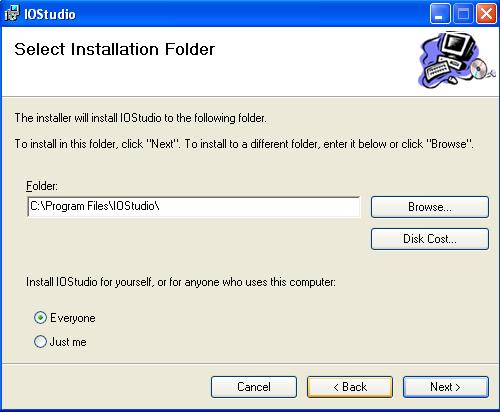
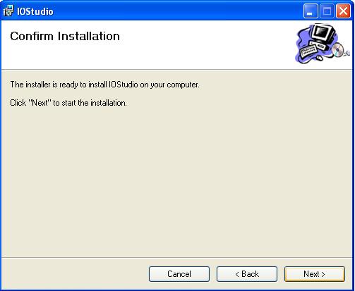
71 FDC_IO_Manual_V1.1_September-2009.doc Page 71 of 82
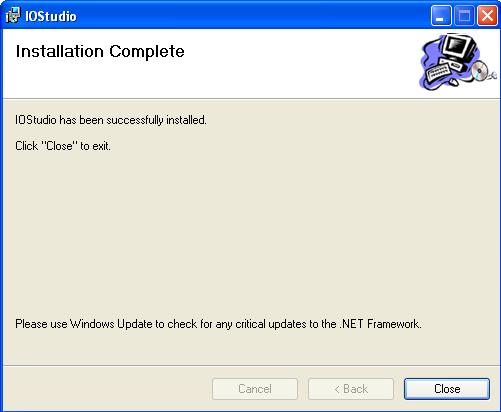
72 FDC_IO_Manual_V1.1_September-2009.doc Page 72 of 82

73 IO Module: Set module modbus address, i.e. 1, for the IO Module using DIP switches on the Module itself. Connect 24V DC Power supply and make sure that Dip switch10 is Off to allow communication of IO Module with other devices on Default communication settings. If you are using RS232/RS485 converter like SNA10A from Future Design Controls, make sure that you have selected all the communication settings properly as follows. BAUD RATE 9600 DATA BITS 8 PARITY NONE STOP BITS 1 In the PC, select above settings at the COM port. Right click on Mycomputer - Properties Hardware - Device Manager - COM ports FDC_IO_Manual_V1.1_September-2009.doc Page 73 of 82

74 Start the IO Studio software as shown above. If everything is set properly, IO Studio will read the IO Module and show the status of the IO registers. If it shows RED indication as above, then please check the dip switch status on the IO Module, RS232/RS485 converter settings, COM settings in the PC and check the cable that is used between PC and RS232/RS485 converter. Many times, you might have more than one COM port on your PC, You should make sure that which COM port is using for this purpose and select the correct COM port in the above shown setup. FDC_IO_Manual_V1.1_September-2009.doc Page 74 of 82
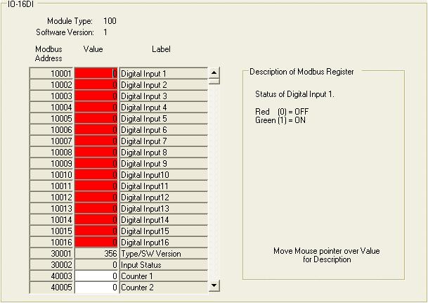
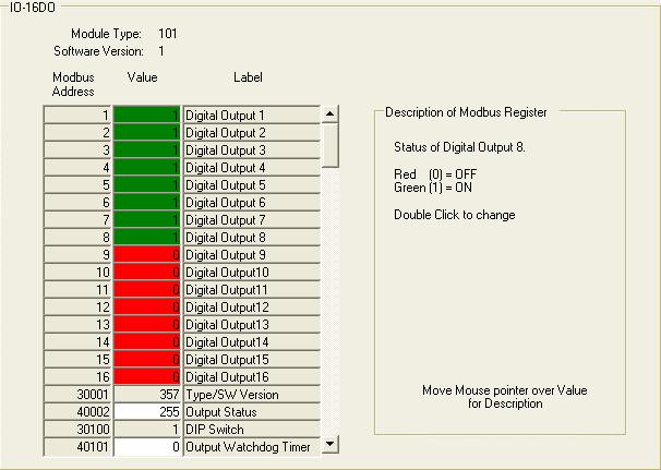
75 FDC_IO_Manual_V1.1_September-2009.doc Page 75 of 82
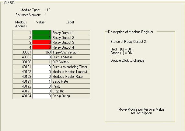
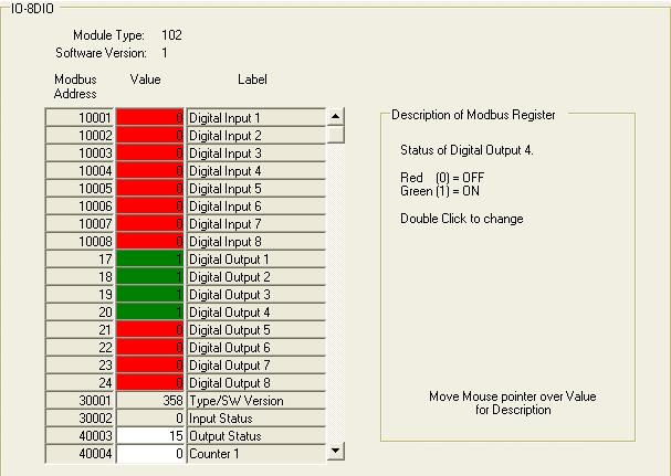
76 FDC_IO_Manual_V1.1_September-2009.doc Page 76 of 82
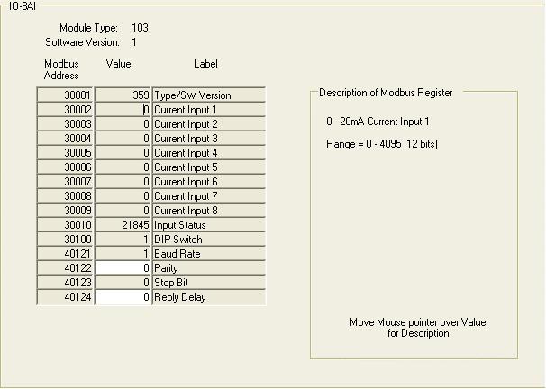
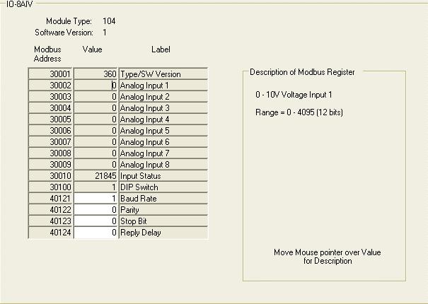
77 FDC_IO_Manual_V1.1_September-2009.doc Page 77 of 82

78 FDC_IO_Manual_V1.1_September-2009.doc Page 78 of 82

79 FDC_IO_Manual_V1.1_September-2009.doc Page 79 of 82
PROMUX Distributed MODBUS I/O Modules Catalog and Design Guide
 PROMUX Distributed MODBUS I/O Modules Catalog and Design Guide 14/11/2006 V10 P.O.Box 24 Stanfield 3613 SOUTH AFRICA Tel: +27 (031) 7028033 Fax: +27 (031) 7028041 Email: proconel@proconel.com Web: www.proconel.com
NetBiter I/O Extender 4RO 6RTD 8DIO - DAIO User Manual Revision 1.00
 NetBiter I/O Extender 4RO 6RTD 8DIO DAIO User Manual Revision 1.00 IntelliCom Innovation AB Linjegatan 3D SE302 50 Halmstad SWEDEN Phone +46 35 18 21 70 Fax +46 35 18 21 99 email info@intellicom.se www
User Manual. Data Acquisition Modules/ Distributed IO Modules
 User Manual Data Acquisition Modules/ Distributed IO Modules UMIOE Rev 5.0, 10/2009 COPYRIGHT NOTICE This manual is a publication of Brainchild Electronics Co.. Ltd. and is provided for use by its customers
PROMUX Distributed MODBUS I/O Modules Catalog and Design Guide
 PROMUX Distributed MODBUS I/O Modules Catalog and Design Guide 12/03/2012 V11.0 P.O.Box 164 Seven Hills 1730 NSW AUSTRALIA Tel: +61 2 96248376 Fax: +61 2 9620 8709 Email: proconel@proconel.com Web: www.proconel.com
User Manual Netbiter IO Extender 4RO 6RTD 8DIO DAIO 8AIx 8AIIx
 User Manual Netbiter IO Extender 4RO 6RTD 8DIO DAIO 8AIx 8AIIx Doc. ID. HMSI27228 Rev. 1.20 Connecting Devices TM HALMSTAD CHICAGO KARLSRUHE TOKYO BEIJING MILANO MULHOUSE COVENTRY PUNE COPENHAGEN HMS Industrial
Netbiter IO Extender 4RO 6RTD 8DIO DAIO 8AIV 8AIIS
 USER MANUAL Netbiter IO Extender 4RO 6RTD 8DIO DAIO 8AIV 8AIIS Doc ID: HMSI-27-228 Version: 2.0 HALMSTAD CHICAGO KARLSRUHE TOKYO BEIJING MILANO MULHOUSE COVENTRY PUNE COPENHAGEN RAVENSBURG HMS Industrial
MODBUS MULTIPLEXING I/O SYSTEM CATALOG AND DESIGN GUIDE
 MODMUX MODBUS MULTIPLEXING I/O SYSTEM CATALOG AND DESIGN GUIDE 22/02/2008 V19 P.O.Box 24 Stanfield 3613 SOUTH AFRICA Tel: 27 (031) 7028033 Fax: 27 (031) 7028041 Email: proconel@proconel.com Web: www.proconel.com
PL420 PROGRAMMABLE LOGIC CONTROLLER
 PL420 PROGRAMMABLE LOGIC CONTROLLER USER MANUAL 12/01/2007 V02 P.O.Box 24 STANFIELD 3613 SOUTH AFRICA Tel: +27 (031) 7028033 Fax: +27 (031) 7028041 Email: proconel@proconel.com Web: www.proconel.com TABLE
Single Channel Loop Detector
 Single Channel Loop Detector Model LD120T Series The LD120T is a series of single channel inductive loop detectors. The use of microprocessor and surface mount technology enables a large number of functions
Industrial Modbus I/O Modules
 Industrial Modbus I/O Modules Modbus I/O Modules Introduction & Features Digital Input / Output Modules Analog Input / Output Modules Modbus I/O Modules The Best Choice For Your SCADA Applications Introduction
Uni-Mux XQL Multi-Channel Data Acquisition Module
 Uni-Mux XQL Multi-Channel Data Acquisition Module Uni-Mux XQL Multi-Channel Data Acquisition Module * 8 channel differential inputs. * 16 channel single ended inputs. * User programmable via P.C. software.
UniStream Uni-I/O Modules
 UniStream Uni-I/O Modules Technical Specifications UIS-WCB1 This guide provides specifications for Unitronics Uni-I/O Wide module UIS-WCB1. This module comprises: 10 Digital inputs, 24VDC, sink/source,
isma-b-w0202 Modbus User Manual GC5 Sp. z o.o. Poland, Warsaw
 isma-b-w0202 isma-b-w0202 Modbus User Manual GC5 Sp. z o.o. Poland, Warsaw www.gc5.com 1. Introduction... 4 2. Safety rules... 4 3. Technical specifications... 5 4. Dimension... 6 5. LED Indication...
PLC-K506 Series FEATURES DESCRIPTION FEATURES
 FEATURES Two High Speed Counters Two Pulse Train Outputs Two Pulse Width Modulation Outputs Inputs 10 Outputs 1 RS232 Port 2 RS485 Ports Supports Modbus RTU Protocol Communicate With Up to 32 Devices DESCRIPTION
CCE Image may differ from the actual product By Martin Labbé, eng., Jasmin Goupil & Louis Perreault
 CCE-32 1.09 Image may differ from the actual product By Martin Labbé, eng., Jasmin Goupil & Louis Perreault Index 1. General description... 5 2. Applications... 5 3. Installation... 5 4. Connections...
Modbus communication module for TCX2: AEX-MOD
 Modbus communication module for TCX2: Communication Specification TCX2 is factory installed in TCX2 series controllers with -MOD suffix, and is also available separately upon request for customer installation
A Super trainer with advanced hardware and software features only found in very expensive equipment.
 PLC Trainer PTS T100 LAB EXPERIMENTS A Super trainer with advanced hardware and software features only found in very expensive equipment. You won t find any similar equipment among our competitors at such
KNC-PLC-K506 Series FEATURES DESCRIPTION FEATURES
 FEATURES Two High Speed Counters Two Pulse Train Outputs Two Pulse Width Modulation Outputs Inputs 10 Outputs 1 RS232 Port 2 RS485 Ports Supports Modbus RTU Protocol Communicate with up to 32 devices DESCRIPTION
Ocean Controls KT-5221 Modbus IO Module
 Ocean Controls Modbus IO Module 8 Relay Outputs 4 Opto-Isolated Inputs 2 Analog Inputs (10 bit) 1 PWM Output (10 bit) 4 Input Counters Connections via Pluggable Screw Terminals 0-5V or 0-20mA Analog Inputs,
Instruction Manual MX-485-S Bi-directional RS485 Data Transceiver
 Instruction Manual MX-485-S Bi-directional RS485 Data Transceiver Copyright 2005, American Fibertek, Inc. 1020JD Table of Contents Functional Description...3 Installation...3 Power Source...3 Power Connection...3
Instruction Manual MTX-8485 MRX-8485 Four Channel Video Multiplexer with Bi-directional Data
 Instruction Manual MTX-8485 MRX-8485 Four Channel Video Multiplexer with Bi-directional Data Copyright 2003, American Fibertek, Inc. 0530JD Table of Contents 2 Functional Description... 4 Installation...
OptiLogic Series. Input/Output Modules. Optimal Automation for Industry. Optimation, Inc. (256)
") Input/Output Modules Optimal Automation for Industry Optimation, Inc. ()-00 WARNING Thank you for purchasing industrial control products from Optimation, Inc. We want your new system to operate safely.
Input/Output Modules Optimal Automation for Industry Optimation, Inc. ()-00 WARNING Thank you for purchasing industrial control products from Optimation, Inc. We want your new system to operate safely.
Analog Module D1-15P User Manual
 D1-15P Manual Analog Module D1-15P User Manual Sielco Elettronica Srl Edison Street 209 20019 Settimo Milanese (MI) - Italy http://www.sielcoelettronica.com info @ sielcoelettronica.com Tel 02 48916252
MV110-8AS. Analog input module 8 channel. User guide
 MV110-8AS Analog input module 8 channel User guide MV110-8AS_2016.12_0226_EN All rights reserved Subject to technical changes and misprints Contents 1 Description... 2 1.1 Function... 2 1.2 RS485 network...
ZZxD-Nx-xR Series. Wireless Modbus I/O B&B ELECTRONICS PRODUCT INFORMATION
 Modular, Customizable Wire Replacement Modbus ASCII /RTU Compatible Wide Operating Temperature Active Repeater Functionality 10 to 48 VDC & 24 VAC Input Power Zlinx Wireless Modbus I/O - flexible enough
The wireless alternative to expensive cabling...
 The wireless alternative to expensive cabling... ELPRO 105U ISO 9001 Certified New Products... New Solutions The ELPRO 105 range of telemetry modules provide remote monitoring and control by radio or twisted-pair
WIRELESS MODBUS GATEWAY WGW410
 WIRELESS MODBUS GATEWAY WGW410 The Tekon Wireless Modbus Gateway WGW410 is specifically designed to meet the most rigorous requirements of operation in the industrial process environments. Due to their
Instruction Manual MTX-8485C MRX-8485C Four Channel Video Multiplexer with Bi-directional Data
 Instruction Manual MTX-8485C MRX-8485C Four Channel Video Multiplexer with Bi-directional Data Copyright 2005, American Fibertek, Inc. 1027JD Table of Contents Functional Description...3 Installation...3
905U Wireless. New Products... New Solutions. The wireless alternative to expensive cabling... Simple but Reliable. Easy to Use
 Wireless New Products... New Solutions The range of telemetry modules provide remote monitoring and control by radio or twisted-pair wire, over short or long distances. Transducer signals connected at
UniStream Built-in. Technical Specifications US7-B5-RA28, US7-B10-RA28 US7-B5-TA30, US7-B10-TA30
 UniStream Built-in Technical Specifications US5-B5-RA28, US5-B10-RA28 US5-B5-TA30, US5-B10-TA30 US7-B5-RA28, US7-B10-RA28 US7-B5-TA30, US7-B10-TA30 Unitronics UniStream Built-in series are PLC+HMI All-in-One
ADAM 4000/4100 Series
 ADAM 4000/4100 Series Common Dimensions Communication RS-485 (2-wire) to host Speeds: 1200, 2400, 4800, 9600, 19200, 38400, 57600, 115200 bps (ADAM-4080, ADAM-4080D only support up to 38400 bps) Max. communication
02/11/2015
 Modem communication plug and play solutions GSM Part number 88970119 For remote control of your application Automatic notification of alarms via SMS (GSM Modem) / email or on a PC with M3 ALARM software.
SRC-110 Series Zone Controllers with Modbus RTU
 Product sheet CT2.142 Type SRC-110-MOD SRC-110 Series Zone Controllers with Modbus RTU The SRC-110 series controllers have been designed for zone heating and cooling control. The controllers have 3 analogue
Model FLSC-C3-XX. DC Powered Microprocessor Controlled Transmitter
 Model FLSC-C3-XX DC Powered Microprocessor Controlled Transmitter CONTENTS. Introduction----------------------------------------------------------------- 2 2. Specifications ---------------------------------------------------------------
USB-TEMP and TC Series USB-Based Temperature Measurement Devices
 USB-Based Temperature Measurement Devices Features Temperature and voltage measurement USB devices Thermocouple, RTD, thermistor, or semiconductor sensor measurements Eight analog inputs Up to ±10 V inputs*
Instruction Manual MX-480 Bi-directional Multi-Protocol Data
 Instruction Manual MX-480 Bi-directional Multi-Protocol Data Copyright 2007, American Fibertek, Inc. 1210JD Table of Contents Functional Description...3 Installation...3 Power Source...3 Power Connection...4
MK110-8D.4R. Digital I/O-Module 12 channel 8 DI, 4 DO. User guide
 MK110-8D.4R Digital I/O-Module 12 channel 8 DI, 4 DO User guide MK110-8D4R_2016.12_0219_EN All rights reserved Subject to technical changes and misprints akytec GmbH Vahrenwalder Str. 269 A 30179 Hannover
BusWorks 900EN Series Modbus TCP/IP 10/100M Industrial Ethernet I/O Modules
 BusWorks 900EN Series Modbus TCP/IP 10/100M Industrial Ethernet I/O Modules Six Differential Current Inputs Six Differential Voltage Inputs USER S MANUAL ACROMAG INCORPORATED Tel: (248) 295-0880 30765
MU110-16R(K) Digital output module 16 channel. User guide
 Digital output module 16 channel. User guide") MU110-16R(K) Digital output module 16 channel User guide MU110-16R(K)_2016.12_0220_EN All rights reserved Subject to technical changes and misprints akytec GmbH Vahrenwalder Str. 269 A 30179 Hannover Germany
MU110-16R(K) Digital output module 16 channel User guide MU110-16R(K)_2016.12_0220_EN All rights reserved Subject to technical changes and misprints akytec GmbH Vahrenwalder Str. 269 A 30179 Hannover Germany
sw rev. 55B DEVICE FOR THE PERMANENT CONTROL OF INSULATION ON THE SUPPLY LINES IN MEDICAL PRACTICE PLACES INSTALLATIONS
 INSTRUCTIONS MANUAL IM831-U v0.92 HRI-R40W sw rev. 55B DEVICE FOR THE PERMANENT CONTROL OF INSULATION ON THE SUPPLY LINES IN MEDICAL PRACTICE PLACES INSTALLATIONS INDEX: GENERAL TYPES ACESSORIES AND OPTIONS
SMARTALPHA RF TRANSCEIVER
 SMARTALPHA RF TRANSCEIVER Intelligent RF Modem Module RF Data Rates to 19200bps Up to 300 metres Range Programmable to 433, 868, or 915MHz Selectable Narrowband RF Channels Crystal Controlled RF Design
UniStream 5" Technical Specifications US5-B5-RA28, US5-B10-RA28
 UniStream 5" Technical Specifications US5-B5-RA28, US5-B10-RA28 Unitronics UniStream 5" are PLC+HMI All-in-One programmable controllers that comprise built-in HMI and built-in I/Os. The series is available
The wireless alternative to expensive cabling...
 The wireless alternative to expensive cabling... ELPRO 105U Wireless Solutions for Process Applications New Products... New Solutions The ELPRO 105U range of wireless I/O provides a low cost alternative
Advanced Ladder Logic Full IEC Languages 25A for <1 24 VDC DC Switched
 EXL6 OCS Datasheet for HE- EXL1E0, HE- EXL1E2, HE- EXL1E3, HE- EXL1E4, HE- EXL1E5, HE- EXL1E6 HEXT371C100, HEXT371C112, HEXT371C113, HEXT371C114, HEXT371C115, HEXT371C116 1. Specifications Required Power
WEL-200 O P E R A T I N G I N S T R U C T I O N S W I R E L E S S E D G E L I N K
 O P E R A T I N G I N S T R U C T I O N S WEL-200 TM W I R E L E S S E D G E L I N K 4564 Johnston Parkway, Cleveland, Ohio 44128 P. 800 426 9912 F. 216 518 9884 Sales Inquiries: salessupport@emxinc.com
USER MANUAL Z-8TC. Via Germania, Z.I. CAMIN PADOVA ITALY. Via Svizzera, Z.I. CAMIN PADOVA ITALY
 USER MANUAL Z-8TC SENECA s.r.l. Via Germania, 34 35127 Z.I. CAMIN PADOVA ITALY Via Svizzera, 17 35127 Z.I. CAMIN PADOVA ITALY Tel. +39.049.8705355 8705359 Fax. +39.049.8706287 Web site: www.seneca.it Technical
The wireless alternative to expensive cabling...
 The wireless alternative to expensive cabling... ELPRO 905U Wireless Solutions for Process Applications New Products... New Solutions The ELPRO 905U range of telemetry modules provide remote monitoring
Quick Start Guide. ELPRO 905U-L-T Wireless I/O Transmitter Unit. man_905u-l-t_quickstart_v1-7.doc
 Quick Start Guide ELPRO 905U-L-T Wireless I/O Transmitter Unit man_905u-l-t_quickstart_v1-7.doc ELPRO 905U-L-T Wireless I/O Transmitter Unit Quick Start Guide About this document This document is the ELPRO
AMERITRON RCS-12 AUTOMATIC ANTENNA SWITCH
 AMERITRON RCS-12 AUTOMATIC ANTENNA SWITCH INSTRUCTION MANUAL PLEASE READ THIS MANUAL BEFORE OPERATING THIS EQUIPMENT! 116 Willow Road Starkville, MS 39759 USA 662-323-8211 Version 3B Printed in U.S.A.
Characteristics and functioning
 Characteristics and functioning /25 ENOD4 PRODUCT RANGE:... 4. General presentation:... 4.2 enodview software tool... 4.3 Versions and options:... 4.3. Versions:...4.3.2 Options :...4.4 Dimensions:...
Shenzhen ATC Technology CO.,LTD ATC. A-1 Serial Remote I/O Module. User Manual. V1.13 Edit:2018/01/
 ATC A-1 Serial Remote I/O Module User Manual V1.13 Edit:2018/01/30-1 - Catalogue 1.The introduction of Modbus protocol...- 3-1.1 Modbus protocol master-slave response process... - 3-1.2 Modbus register
AMU-214 Auxiliary Monitor Unit Operations Manual
 AMU-214 Auxiliary Monitor Unit THIS MANUAL CONTAINS TECHNICAL INFORMATION FOR THE AMU-214 SERIES ITS CABINET AUXILIARY MONITOR UNIT. REVISION: SEPTEMBER 2008 pn 888-0214-001 THE AMU-214 SERIES AUXILIARY
VFSC9 ELECTRONIC SPEED CONTROLLER. Mounting and operating instructions
 ELECTRONIC SPEED CONTROLLER Mounting and operating instructions Table of contents SAFETY AND PRECAUTIONS 3 PRODUCT DESCRIPTION 4 ARTICLE CODES 4 INTENDED AREA OF USE 4 TECHNICAL DATA 4 STANDARDS 5 WIRING
SCADA and Telemetry Solutions. SCADALink IO900. Modular Wireless I/O System. User Manual Version V1.3 for SCADALink IO900 BENTEK SYSTEMS LTD
 Modular Wireless I/O System User Manual Version V. for BENTEK SYSTEMS LTD #, 0 Ave S.E. Calgary, AB, Canada TB 0L Ph:(0) Fax:(0) email: sales@scadalink.com web: The is a Modular Wireless I/O System that
Instruction Manual MT-945SL Four Channel Video Transmitter With Two Bi-Directional Data Channels
 Instruction Manual MT-945SL Four Channel Video Transmitter With Two Bi-Directional Data Channels Copyright 2006, American Fibertek, Inc. 0307JD Table of Contents Functional Description... 3 Installation...
MU110-8R(K) Digital output module 8 channel. User guide
 Digital output module 8 channel. User guide") MU110-8R(K) Digital output module 8 channel User guide MU110-8R(K)_2019.01_0296_EN All rights reserved Subject to technical changes and misprints akytec GmbH Vahrenwalder Str. 269 A 30179 Hannover Germany
MU110-8R(K) Digital output module 8 channel User guide MU110-8R(K)_2019.01_0296_EN All rights reserved Subject to technical changes and misprints akytec GmbH Vahrenwalder Str. 269 A 30179 Hannover Germany
F2A3X Frequency to Analog Converter Module
 the professional s choice F2A3X Frequency to Analog Converter Module Instruction Manual MONARCH INSTRUMENT 15 Columbia Drive Amherst, NH 03031 USA Phone: (603) 883-3390 Fax: (603) 886-3300 E-mail: support@monarchinstrument.com
Characteristics and functioning
 Characteristics and functioning 1/36 enod4-d Characteristics and functioning NU-eNod4D-ETH-E-1014_216710-A 1 ENOD4 PRODUCT RANGE... 5 1.1 General presentation... 5 1.2 Versions and options... 5 1.2.1 Versions...
02/11/2015
 Modem communication plug and play solutions GSM Part number 88970119 For remote control of your application Automatic notification of alarms via SMS (GSM Modem) / email or on a PC with M3 ALARM software.
PM-311x Quick Start Ver PM-311x introduction 1.1. Caution & Warning 1.2. Product Warranty & Customer Support
 PM-311x Quick Start Ver. 1.1 1. PM-311x introduction ICP DAS brings the most powerful, cost-effective, advanced Smart Power Meters PM-3000 series that gives you access to real-time electric usage for single-phase
301 & 601 Mic/Line Mixers Operation Manual
 301 & 601 Mic/Line Mixers Operation Manual Biamp Systems 9300 S.W. Gemini Drive Beaverton, OR 97008 USA +1.503.641.7287 www.biamp.com 301 & 601 TABLE OF CONTENTS Introduction Front Panel Rear Panel Remote
UNICOM 2500 UNICOM Installation Operation Programming. Universal Communication Converter
 User Manual UNICOM 2500 Installation Operation Programming Universal Communication Converter UNICOM 2500 Electro Industries/GaugeTech 1800 Shames Drive Westbury, New York 11590 Tel 516.334.0870 Fax 516.338.4741
This Errata Sheet contains corrections or changes made after the publication of this manual.
 Errata Sheet This Errata Sheet contains corrections or changes made after the publication of this manual. Product Family: DL4 Date: September 12, 218 Manual Number D4-ANLG-M Revision and Date th Ed., Rev.
High Performance Process & Temperature Controllers
 C22 C62 C82 C83 High Performance Process & Temperature Controllers C72 C42 R22 01. Multi Color LCD Display 02. High Accuracy 18 Bit A-D Input and 15 Bit D-A Output 03. 200 msec Sampling Rate 04. True Universal
ERV-M ELECTRONIC FAN SPEED CONTROLLER. Mounting and operating instructions
 ELECTRONIC FAN SPEED CONTROLLER Mounting and operating instructions Table of contents SAFETY AND PRECAUTIONS 3 PRODUCT DESCRIPTION 4 ARTICLE CODES 4 INTENDED AREA OF USE 4 TECHNICAL DATA 4 STANDARDS 5
PROCESS & TEMPERATURE CONTROLLERS
 PROCESS & TEMPERATURE CONTROLLERS NOVA PD54 Series Thermocouple, RTD, & Process Inputs High Accuracy Auto-Tuning PID Heating & Cooling Models Universal Power Supply 1-24 VAC Up to 3 Relays & 2 Analog Outputs
The wireless alternative to expensive cabling...
 The wireless alternative to expensive cabling... ELPRO 905U Wireless Solutions for Process Applications New Products... New Solutions The ELPRO 905U range of wireless I/O provides a low cost alternative
Table of Contents. HWIO-Gateway User Manual
 User Manual HWIO-Gateway INUX AB Katrinedalsg. 3, 504 51 Borås http://www.inux.se Copyright 2009 Uppdaterad 2010-01-12 Copyright 2009 INUX AB 1 Table of Contents 1. Product overview...3 2. License...3
CONTA-ELECTRONICS. Converter Units
 CONTA-ELECTRONICS Whether for manufacturing, electrical machine and plant instrumentation, control engineering, power distribution, building automation, or process engineering it is always important to
BATCHMATE 1500 Batch Control Computer Technical Bulletin
 TS-5(C) BATCHMATE 5 Batch Control Computer Technical Bulletin DESCRIPTION The BATCHMATE features an 8 digit.55-in. alphanumeric LED display. The pulse input model will accept up to 2, pulses per second
Zlinx Wireless I/O. Peer-to-Peer and Modbus I/O PRODUCT INFORMATION B&B ELECTRONICS
 Zlinx Wireless Modbus I/O-0712ds page 1/5 Modular, Customizable Wire Replacement 128 / 256 Bit AES Encryption Software Selectable RF Transmit Power Software Selectable Over-the-air Data Rate Modbus ASCII
Fuzzy Temperature Controllers E5AF
 Fuzzy Temperature Controllers 1/4 DIN Controller Combines Fuzzy and PID Control For Fast Response to Process Disturbances Advanced PID control provides optimal response during start-up and steadystate
The MP SERIES CONTROLLER. User s Manual. ISE, Inc.
 The MP SERIES CONTROLLER User s Manual ISE, Inc. 10100 Royalton Rd. Cleveland, OH 44133 USA Tel: (440) 237-3200 Fax: (440) 237-1744 http://variac.com Form No, 003-1622 Rev G 02/25/2009 Form No. 003-1622
269 Troubleshooting Guide 11/4/98 1
 269 Troubleshooting Guide 11/4/98 1 Table of Contents Phase currents 3 Communications. 6 RTDs.. 9 Ground Fault Currents... 13 Output Relays. 15 Analog Output 17 Switch Inputs...18 11/4/98 2 Phase Currents
VersaPoint I/O Module
 GFK-2012A March 2010 Module provides two-input channels for measuring signals from standard thermocouples. It supports thirteen different thermocouples types. In addition, it accepts linear voltage inputs
ioselect Z-NET Z-4RTD 4 Channel RTD Input Module
 4 Channel nput Module : PT00, PT000, PT500 & N00: 2, 3 & 4 wire 500 V solation, 6-way Modbus Communications Adjustable Sampling Time Accuracy to 0.2 C Configuration and Setup Software EC 63 Flexible Power
GE Fanuc IC695ALG600. Rx3i PacSystem
 GE Fanuc IC695ALG600 http://www.pdfsupply.com/automation/ge-fanuc/rx3i-pacsystem/ic695alg600 Rx3i PacSystem UNIVERSAL ANALOG MODULE. 8 CHANNELS OF ANALOG CONFIGURABLE IC695A IC695AL IC695ALG 919-535-3180
LAUREL ELECTRONICS, INC.
 LAUREL ELECTRONICS, INC. Laureate True RMS AC Voltage & Current Meter with 1 Cycle Update at 50/60 Hz Features True AC or AC plus DC RMS measurement with crest factor of 3.0 at FS Fast response: reading
MULTIFUNCTION GRAPHICAL UNIT MGU 800
 MULTIFUNCTION GRAPHICAL UNIT MGU 800 For display, recording and evaluation of process instruments signals (level, temperature, pressure, etc.) 3.5" TFT display, multi-language menu Variety of possible
af i Instruction Manual MR-944C Four Channel Video Receiver With One Bi-Directional Multi-Protocol Data Channel american fibertek 11/30/2012 JPK
 af i american fibertek Instruction Manual MR-944C Four Channel Video Receiver With One Bi-Directional Multi-Protocol Data Channel 11/30/2012 JPK Table of Contents Functional Description... 3 Installation...
Instruction Manual TABLE OF CONTENTS 1 PRINCIPLE OF OPERATION Limitations INSTALLATION Mains connection...
 instrumentación para fluidos CI- pulse / ma Converter Instruction Manual TABLE OF CONTENTS PRINCIPLE OF OPERATION.... Limitations.... INSTALLATION.... Mains connection........ Input connection........
USER MANUAL MODEL Parallel to Serial/ Serial to Parallel Interface Converter
 USER MANUAL MODEL 2029 Parallel to Serial/ Serial to Parallel Interface Converter C E R T I F I E D An ISO-9001 Certified Company Part #07M2029-B, Rev. C Doc. #102011UB Revised 6/16/09 SALES OFFICE (301)
CPU 221, CPU 222, CPU 224, CPU 224 XP, CPU 224 XPsi, CPU 226
 Siemens AG 2008 SIMATIC S7-200 Overview CPU 226 The high-performance package for complex technical tasks With additional PPI port for added flexibility and communication options With 40 inputs/outputs
MV110-8A. Analog input module 8 channel. User guide
 MV110-8A Analog input module 8 channel User guide MV110-8A_2016.12_0225_EN All rights reserved Subject to technical changes and misprints Contents 1 Description... 2 1.1 Function... 2 1.2 RS485 network...
ISO 9001 CERTIFIED. 607 NW 27th Ave Ocala, FL Phone: (352) or Fax: (352) OPERATION MANUAL
 or Fax: (352) OPERATION MANUAL") ISO 9001 CERTIFIED Phone: (352) 629-5020 or 800-533-3569 Fax: (352)-629-2902 ES-Key 12 PDM module (4 selectable polarity outputs) with 4 Inputs (selectable polarity) and 4 MFI Inputs P/N 610-00035 PAGE
ISO 9001 CERTIFIED Phone: (352) 629-5020 or 800-533-3569 Fax: (352)-629-2902 ES-Key 12 PDM module (4 selectable polarity outputs) with 4 Inputs (selectable polarity) and 4 MFI Inputs P/N 610-00035 PAGE
Status Indicator LED PWR LINK COL
 INSTRUCTION MANUAL DC VOLTAGE/CURRENT INPUT MODULE, 4 points (Ethernet Modbus/TCP) MODEL RE-SV4 RE-SV4 BEFORE USE... Thank you for choosing M-System. Before use, please check contents of the package you
Z-10-D-IN. RS485 Modbus Module 10 Digital Inputs
 S SENECA Z-PC Line EN Installation Manual Contents: - General specifications - Technical specifications - Installation rules - Electrical connections - Modbus connection rules - DIP-switches settings -
Excellent low-cost Process & Temperature Controllers
 C22 C62 C82 C83 Excellent low-cost Process & Temperature Controllers C72 C42 R22 01. High Quality LCD Display 02. High Accuracy 18 Bit A-D Input and 15 Bit D-A Output 03. The Fast Sampling Rate in 200
MULTI-DROPS DIGITAL MODEM FOR PRIVATE LINE
 Distribué par : Contact : hvssystem@hvssystem.com Tél : 0326824929 Fax : 0326851908 Siège social : 2 rue René Laennec 51500 Taissy France www.hvssystem.com MDM192 MULTI-DROPS DIGITAL MODEM FOR PRIVATE
Quick Start Guide. ELPRO 105U-L-T Wireless I/O Transmitter Unit. man_105u-l-t_quickstart_v1-8.doc
 Quick Start Guide ELPRO 105U-L-T Wireless I/O Transmitter Unit man_105u-l-t_quickstart_v1-8.doc ELPRO 105U-L-T Wireless I/O Transmitter Unit Quick Start Guide About this document This document is the ELPRO
Selection guide. Communication accessories. Communication accessory selection guide. Characteristics
 Communication accessories Selection guide There are 2 types of Sepam communication accessories: b communication interfaces, which are essential for connecting Sepam to the communication network b converters
B850 Boiler House Energy Monitor
 Local regulations may restrict the use of this product to below the conditions quoted. In the interests of development and improvement of the product, we reserve the right to change the specification without
815LT Submersible Smart Level Transmitter
 These instructions provide information for installation, process connection, electrical connection, configuration, operation and maintenance of the 815LT Submersible Smart Level Transmitter. The 815LT
K-Factor Scaler F5140 and Programming Kit F5141 Installation & Operating Instructions
 F5140 and Programming Kit F5141 8635 Washington Avenue Racine, WI 53406 USA Tel: 800-433-5263 or 262-639-6770 Fax: 800-245-3569 or 262-639-2267 E-Mail: flo-techsales@racinefed.com www.flo-tech.com TABLE
Temperature Transmitters - Head Mounted
 XTH Features - Non-programmable Models Sensor Types: Models for thermocouple Types J, K, or T Models for RTD Type Pt100 3-wire Select from a variety of pre-configured measuring ranges Internal cold junction
USER MANUAL. MODEL 457B Seven Port Active Twinax Star Hub. SALES OFFICE (301) TECHNICAL SUPPORT (301)
 TECHNICAL SUPPORT (301)") USER MANUAL MODEL 457B Seven Port Active Twinax Star Hub An ISO-9001 Certified Company Part #07M457B-C Doc. #069011UC Revised 4/22/98 SALES OFFICE (301) 975-1000 TECHNICAL SUPPORT (301) 975-1007 http://www.patton.com
USER MANUAL MODEL 457B Seven Port Active Twinax Star Hub An ISO-9001 Certified Company Part #07M457B-C Doc. #069011UC Revised 4/22/98 SALES OFFICE (301) 975-1000 TECHNICAL SUPPORT (301) 975-1007 http://www.patton.com
UL CONDITIONS OF ACCEPTABILITY
 Certificate Number: 1018011-1 Date: 2016-10-06 UL CONDITIONS OF ACCEPTABILITY Company Name: FUTURE DESIGN CONTROLS INC File-CCN: E197216 - QUYX2 Product Description: Process Control Equipment, Electrical
VersaMax Mixed Discrete / High-Speed Counter Module
 Product Description The VersaMax Mixed Discrete High-Speed Counter (HSC) module,, has twenty 24VDC positive-logic type inputs and twelve positive-logic 24VDC 0.5Amp outputs. In its default configuration,
PULSE INPUT MODULE PI232/PI272 USER S MANUAL
 UM-TS02 -E021 PROGRAMMABLE CONTROLLER PROSEC T2-series PULSE INPUT MODULE PI232/PI272 USER S MANUAL TOSHIBA CORPORATION Important Information Misuse of this equipment can result in property damage or human
Fiber Optic Expansion Interface
 User Manual for the HE697FBX100 & HE697FBX105 Fiber Optic Expansion Interface Fourth Edition 20 November 1998 MAN0215-04 PREFACE 20 NOV 1998 PAGE 2 PREFACE This manual explains how to use the Fiber Optic