Ratings Ratings SPST-NO SPDT DPST-NO DPDT
|
|
|
- Norman Owen
- 5 years ago
- Views:
Transcription
 and highcapacity (6 A) types available. Doublewinding latching type available.")
1 A Power Relay for a Variety of Purposes with Various Models Conforms to EN 680, UL8, CSA., SEV, SEMKO. Meets VDE0700 requirements for household products according to VDE00. Clearance and creepage distance: 8 mm/8 m. Models with CTI material available. Highsensitivity (360 mw) and highcapacity (6 A) types available. Doublewinding latching type available. Plugin with test button and quickconnect terminals available. Highly functional socket available. XVDE RC+SE Ordering Information Classification Enclosure Coil Contact Form Ratings Ratings SPSTNO SPDT DPSTNO DPDT PCB terminal Generalpurpose Flux protection AC/DC GRA GR GRA GR Fully sealed GRA GR GRA GR Bifurcated contact Flux protection DC GRAZ GRZ Fully sealed GRAZ GRZ Highcapacity Flux protection AC/DC GRAE GRE Highsensitivity Flux protection DC GRAH GRH GRAH GRH Doublewinding latching Flux protection GRKA GRK GRKA GRK Plugin terminal Generalpurpose Unsealed AC/DC GRS GRS LED indicator GRSN GRSN LED indicator with GRSNI GRSNI test button Diode DC GRSD GRSD LED indicator and diode GRSND GRSND LED indicator and GRSNDI GRSNDI diode with test button Plugin terminal Generalpurpose AC/DC GRA3S GR3S (Bifurcated crossbar contact) LED indicator GRA3SN GR3SN LED indicator and diode DC GRA3SND GR3SND Note:. When ordering, add the rated coil voltage to the model number. Example: GRA VDC Rated coil voltage. OMRON has also prepared the above relays with AgSnIn contacts, which are more tolerant of large inrush currents and physical movement compared with relays with standard contacts. When ordering, add "ASI" to the model number. Example: GRAASI 3. Standard, NO contact type relays are TV3 class products in accordance with the TV standards of the UL/CSA. Models with AgSnIn contacts are TV class products. Example: GRAASI When ordering a TV8 class model, insert "TV8" into the model number as follows: Example: GRATV8ASI. Models with CTI material are also available. Contact your OMRON representative for more details. 09
2 Model Number Legend GR VDC Relay Function None: Singleside stable K: Doublewinding latching. Number of Poles : pole : poles 3. Contact Form None: PDT A: PSTNO. Contact Type None: Single Z: Bifurcated 3: Bifurcated crossbar. Enclosure Ratings None: Flux protection : Fully sealed 6. Terminals None: Straight PCB S: Plugin T: Quickconnect (upper bracket mounting) 7. Classification None: Generalpurpose E: Highcapacity H: Highsensitivity N: LED indicator D: Diode ND: LED indicator and diode 8. Test button I: Test button Note: Applied for only SN and SND type 9. Contact Material None: AgCdO (Cd free planned Apr 0) ASI: AgSnIn 0.Rated Coil Voltage Refer to Coil Ratings Accessories (Order Separately) Connecting Sockets Number of Poles Applicable Relay Track/surfacemounting Model Socket pole GR PRF0E S(N)(D)(ND)(NI)(NDI)GR PRF0 3S (GRA3S) Poles GRS(N)(D)(ND)(NI)(NDI) PRF08E PRF08 Backmounting Socket Terminals Model PCB terminals PR0P, PR07P Solder terminals PR0A PCB terminals PR08P, PR087P Solder terminals PR08A Note: See Dimensions for details on socket size. Mounting Track Applicable socket Description Model Track connecting socket Mounting track cm (l) x 7.3 mm (t): PFPN m (l) x 7.3 mm (t): PFPN m (l) x 6 mm (t): PFPN End plate PFPM Spacer PFPS Back connecting socket Mounting plate PRP* *Used to mount several PR0A and PR08A connecting sockets side by side. 0
3 Specifications Coil Ratings Rated voltage VAC VAC /(0) VAC VAC 0/()VAC VAC 30 VAC VAC Rated Current Hz 60Hz 93 ma 6. ma ma 9.3 ma. (.0) ma. ma.7 (3.7) ma.7 ma 7 ma 37. ma 9/(0.6) ma 7. ma. (.3) ma. ma 3.8 (3.) ma 3.8 ma Coil resistance 6 Ω 60 Ω,600 Ω 6, Ω,0 Ω 6,8 30,000 Ω () Ω (30,000) Ω Coil inductance Armature OFF (H) (ref. value) Armature ON Must operate voltage Must release voltage Max. voltage Power consumption % max. of rated voltage 30% min. of rated voltage 0% of rated voltage (at 3 C) Approx. 0.9 VA at 60 Hz (approx. 0.7 VA at 60 Hz) Note:. Rated voltage of bifurcated crossbar contact type: /(0) VAC, 0/() VAC, 30 VAC (Approx. 0.7 VA at 60 Hz).. Depending on the type of Relay, some Relays do not have coil specifications. Contact your OMRON representative for more details. Rated voltage VDC 6 VDC VDC VDC 8 VDC VDC Rated current (/60Hz) 06 ma 88. ma 3.6 ma.8 ma. ma.3 ma Coil resistance 7 Ω 68 Ω 7 Ω, Ω,70 Ω 8,860 Ω Coil inductance Armature OFF (H) (ref. value) Armature ON Must operate voltage 70% max. of rated voltage Must release voltage % min. of rated voltage Max. voltage 70% of rated voltage (at 3 C) Power consumption Approx. 0.3 W Note: Rated voltage of bifurcated crossbar contact type: VDC, VDC Highsensitivity Relays Rated voltage VDC 6 VDC VDC VDC 8 VDC Rated current (/60Hz) 7. ma 60 ma 30 ma ma 7. ma (see Note. ) Coil resistance (see Note. ) 70 Ω Ω 00 Ω,600 Ω 6,00 Ω Coil inductance Armature OFF (H) (ref. value) Armature ON Must operate voltage Must release voltage Max. voltage Power consumption % max. of rated voltage % min. of rated voltage 70% of rated voltage (at 3 C) Approx W Note:. The rated current and coil resistance are measured at a coil temperature of 3 C with a tolerance of +% / % (AC rated current) or ±0% (DC coil resistance). LEDs are used for the builtin operation indicator. For models equipped with these indications, the VAC rated current must be increased by approximately ma; the VDC rated current, by approximately ma. 3. Operating characteristics are measured at a coil temperature of 3 C.
4 Doublewinding Latching Relays Rated voltage VDC 6 VDC VDC VDC Set Coil Rated current (see note.) 67 ma 38 ma 70.6 ma 3.6 ma Reset Coil Must set voltage Must reset voltage Max. voltage Power consumption Contact Ratings Coil resistance (see note.) 30 Ω 3. Ω 70 Ω 69 Ω Coil inductance Armature OFF (H) (ref. value) Armature ON PCB/Flux Protection, Plugin, Quickconnect Terminal Relays Rated current 9 ma ma ma ma Coil resistance Ω 60 Ω Ω 960 Ω Coil inductance Armature OFF (H) (ref. value) Armature ON % max. of rated voltage 70% max. of rated voltage 0% of rated voltage (at 3 C) Set coil: Approx. 8 mw; Reset coil: Approx. 600 mw Note:. The rated current and coil resistance are measured at a coil temperature of 3 C with a tolerance of ±0%.. Operating characteristics are measured at a coil temperature of 3 C. Item Generalpurpose, quickconnect terminal Highcapacity Number of poles pole poles pole Load Resistive load Inductive load Resistive load Inductive load Resistive load Inductive load (cosø = ) (cosø = 0.; (cosø = ) (cosø = 0.; (cosø = ) (cosø = 0.; L/R = 7 ms) L/R = 7 ms) L/R = 7 ms) Rated Load 0 () A at VAC; 7. A at A at VAC; A at VAC; 6 A at VAC; 8 A at VAC; 0 () A at 30 VDC VAC; A at 30 VDC 3 A at 30 VDC 6 A at 30 VDC 8 A at 30 VDC A at 30 VDC Rated carry current 0 () A A 6 A Max. switching voltage 380 VAC, VDC 380 VAC, VDC 380 VAC, VDC Max. switching current 0 () A A 6 A Max. switching power, () VA,,87 VA,, VA, VA,,000 VA,,000 VA, 300 (30) W W W 90 W 80 W W Failure rate ma at VDC ( ma at VDC) 0 ma at VDC ma at VDC (reference value) Note:. P level: λ 60 = 0. x 0 6 /operation.. ( ): Bifurcated crossbar contact type.
5 PCB/Flux Protection Relays Item Bifurcated contacts Highsensitivity Number of poles pole pole poles Load Resistive load Inductive load Resistive load Inductive load Resistive load Inductive load (cosø = ) (cosø = 0.; (cosø = ) (cosø = 0.; (cosø = ) (cosø = 0.; L/R = 7 ms) L/R = 7 ms) L/R = 7 ms) Rated Load A at VAC; A at VAC; A at VAC; A at VAC; 3 A at VAC; A at VAC; A at 30 VDC 3 A at 30 VDC A at 30 VDC 3 A at 30 VDC 3 A at 30 VDC. A at 30 VDC Rated carry current A A 3 A Max. switching voltage 380 VAC, VDC 380 VAC, VDC 380 VAC, VDC Max. switching current A A 3 A Max. switching power, VA, VA,, VA, VA, 7 VA, VA, W 90 W W 90 W 90 W W Failure rate ma at VDC ma at VDC 0 ma at VDC (reference value) Note: P level: λ 60 = 0. x 0 6 /operation. PCB/Fully Sealed Relays Item Generalpurpose (single contact) Bifurcated contact Number of poles pole poles pole Load Resistive load Inductive load Resistive load Inductive load Resistive load Inductive load (cosø = ) (cosø = 0.; (cosø = ) (cosø = 0.; (cosø = ) (cosø = 0.; L/R = 7 ms) L/R = 7 ms) L/R = 7 ms) Rated Load 8 A at VAC; 6 A at VAC; A at VAC;. A at VAC; A at VAC; A at VAC; 8 A at 30 VDC A at 30 VDC A at 30 VDC. A at 30 VDC A at 30 VDC 3 A at 30 VDC Rated carry current 8 A A A Max. switching voltage 380 VAC, VDC 380 VAC, VDC 380 VAC, VDC Max. switching current 8 A A A Max. switching power,000 VA,, VA, VA, 37 VA,, VA, VA, W W W 7 W W 90 W Failure rate ma at VDC 0 ma at VDC ma at VDC (reference value) Note: P level: λ 60 = 0. x 0 6 /operation. Latching Relays Number of poles pole poles Load Resistive load Inductive load Resistive load Inductive load (cosø = ) (cosø = 0.; (cosø = ) (cosø = 0.;; L/R = 7 ms) L/R = 7 ms) Rated Load A at VAC; 3. A at VAC; 3 A at VAC;. A at VAC; A at 30 VDC. A at 30 VDC 3 A at 30 VDC A at 30 VDC Rated carry current A 3 A Max. switching voltage 380 VAC, VDC Max. switching current A 380 VAC, VDC Max. switching power, VA, W 87 VA, 7 W 7 VA, 90 W 37 VA, 60 W Failure rate ma at VDC 0 ma at VDC (reference value) Note: P level: λ 60 = 0. x 0 6 /operation. 3 A 3
6 Characteristics Standard Relays Item Pole Poles Contact resistance 30 mω max. (highcapacity type: mω max.) mω max. Operate (set) time Release (reset) time Max. operating frequency Insulation resistance ms max AC: 0 ms max.; DC: ms max. (w/builtin diode: ms max.) Mechanical: 8,000 operations/hr Electrical:,800 operations/hr (under rated load) MΩ min. (at VDC) Dielectric strength VAC, /60 Hz for min VAC, /60 Hz for min between coil and contacts*; between coil and contacts*; VAC, /60 Hz for min 3,000 VAC, /60 Hz for min between contacts of same polarity between contacts of different polarity VAC, /60 Hz for min between contacts of same polarity Vibration resistance Destruction: 0 to to 0 Hz, 0.7mm single amplitude (.mm double amplitude) Malfunction: 0 to to 0 Hz, 0.7mm single amplitude (.mm double amplitude) Shock resistance Destruction: m/s Malfunction: 0 m/s when energized; m/s when not energized Endurance Ambient temperature Mechanical: AC coil: 0,000,000 operations min.; DC coil:,000,000 operations min. (at 8,000 operations/hr) Electrical:,000 operations min. (at,800 operations/hr under rated load) Operating: 0 C to 70 C (with no icing) Ambient humidity Operating: % to 8% Weight Approx. 7 g (plugin terminal: approx. g) Note: Values in the above table are the initial values. *,000 VAC, /60 Hz for minute when the PR0A or PR08A socket is mounted.
7 Doublewinding Latching Relays Item Pole Poles Contact resistance 30 mω max. mω max. Set time Reset time Min. set/reset signal width Max. operating frequency Insulation resistance ms max ms max. 30 ms max. Mechanical: 8,000 operations/hr Electrical:,800 operations/hr (under rated load) MΩ min. (at VDC) Dielectric strength VAC, /60 Hz for min VAC, /60 Hz for min between coil and contacts*; between coil and contacts*; VAC, /60 Hz for min 3,000 VAC, /60 Hz for min between contacts of same pole; between contacts of different poles VAC, /60 Hz for min VAC, /60 Hz for min between set and reset coil between contacts of same pole VAC, /60 Hz for min between set and reset coil Vibration resistance Destruction: 0 to to 0 Hz, 0.7mm single amplitude (.mm double amplitude) Malfunction: 0 to to 0 Hz, 0.7mm single amplitude (.mm double amplitude) Shock resistance Destruction: m/s (approx. G) Malfunction: Set: m/s (approx. G); 0 m/s (approx. G) Reset: m/s (approx. 0G) Endurance Ambient temperature Mechanical: 0,000,000 operations min (at 8,000 operations/hr) Electrical:,000 operations min. (at,800 operations/hr under rated load) Operating: 0 C to 70 C (with no icing) Ambient humidity Operating: % to 8% Weight Approx. 7 g Note: Values in the above table are the initial values. *,000 VAC, /60 Hz for minute when the PR0A or PR08A socket is mounted.
8 Approved Standards UL 8 (File No. E63) Model Contact form Coil ratings Contact ratings GR SPDT 3 to 0 VDC 0 A, 30 VDC (resistive) GR 3 to VAC 0 A, VAC (general use) GRH TV3 (NO contact only) GRS GRT GRA SPSTNO GRA GRAH GRAS GRAT GRE SPDT 6 A, 30 VDC (resistive, NO contact only) 6 A, VAC (general use, NO contact only) GRAE SPSTNO TV3 (NO contact only); /3 hp, VAC GR DPDT A, 30 VDC (resistive) GR A, VAC (general use) GRH TV3 (NO contact only) GRS GRA DPSTNO GRA GRAH GRAS GRAASI SPSTNO 0 A, 30 VDC (resistive) 0 A, VAC (general use) TV/TV8 (NO contact only) CSA. No.0, No. (File No. LR398) Model Contact form Coil ratings Contact ratings GR SPDT 3 to 0 VDC 0 A, 30 VDC (resistive) GR 3 to VAC 0 A, VAC (general use) GRH TV3 (NO contact only) GRS GRT GRA SPSTNO GRA GRAH GRAS GRAT GRE SPDT 6 A, 30 VDC (resistive, NO contact only) 6 A, VAC (general use, NO contact only) GRAE SPSTNO TV3 (NO contact only) GR DPDT A, 30 VDC (resistive) GR A, VAC (general use) GRH TV3 (NO contact only) GRS GRA DPSTNO GRA GRAH GRAS GRAASI SPSTNO 0 A, 30 VDC (resistive) 0 A, VAC (general use) TV8 (NO contact only); / hp, VAC 6
9 SEV Contact form Coil ratings Contact ratings pole 3 to 0 VDC 6 A, VAC (AgSnIn contact) 3 to VAC 6 A, 30 VDC (AgSnIn contact) 0 A, VAC A, VAC3 0 A, 30 VDC poles 3 to 0 VDC A, VAC 3 to VAC A, 380 VAC A, 30 VDC SEMKO Contact form Coil ratings Contact ratings pole 3 to 0 VDC 0/80 A, VAC 3 to VAC 3/ A, VAC 6/8 A, VAC (AgSnIn contact) poles /0 A, VAC TÜV (IEC ) Contact form Coil ratings Contact ratings pole 3 to 0 VDC, 6 VAC to VAC (for Standard coil) 3 to 8 VDC (for K, U coil) 3 to 70 VDC (for H coil) 0 A, VAC (cosø =.0) 0 A, 30 VDC (0 ms) 6 A, VAC (cosø =.0) (AgSnIn contact) poles 8 A, VAC (cosø = 0.) A, VAC (cosø =.0) A, 30 VDC (0 ms). A, VAC (cosø = 0.) EN 680 (VDE IEC, VDE 03 IMQ VDE Reg No. 666) Contact form Coil ratings Contact ratings pole, 6, 9,, 8,, 8, 60,, 0 VDC 0 A, VAC (cosø =.0), 8,, 8,, /(0), 0,, 0 A, 30 VDC (0 ms) 0/(),, 30, VAC 6 A, VAC (cosø =.0) poles, 6, 9,, 8,, 8, 60,, 0 VDC A, VAC (cosø =.0), 8,, 8,, /(0), 0,, A, 30 VDC (0 ms) 0/(),, 30, VAC 7


 GRH, GRAH, GR")

 GRKA, GRK")
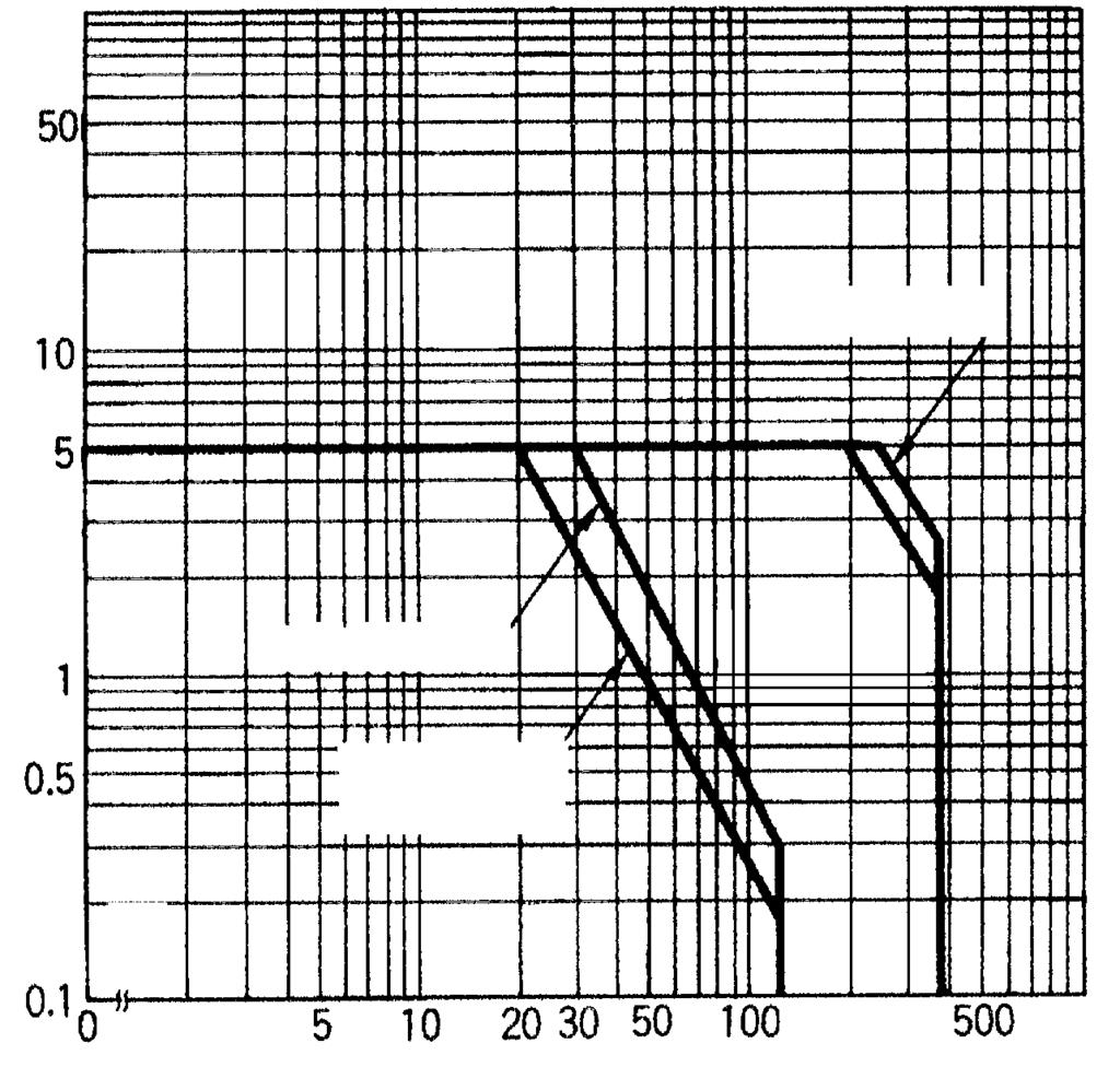
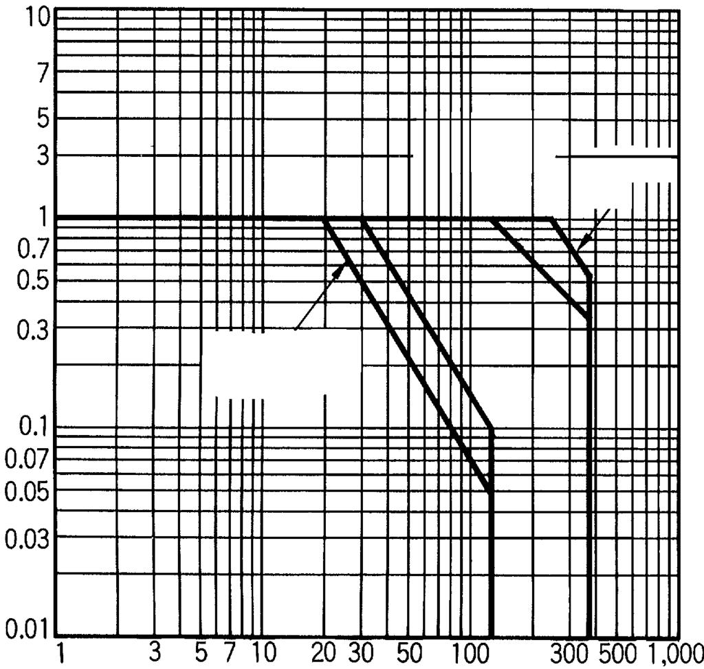
10 Engineering Data Maximum Switching Power Flux Protection/Plugin Relays GR, GRA, GRS, GRT, GRAT GRE, GRAE GRZ, GRAZ DC AC DC AC DC AC Switching voltage (V) Switching voltage (V) Switching voltage (V) GRH, GRAH, GR GRA, GRS GRH, GRAH GR3S, GRA3S DC AC DC AC DC AC resistive load Switching voltage (V) Switching voltage (V) Switching voltage (V) GRKA, GRK GRKA, GRK DC AC DC AC Switching voltage (V) Switching voltage (V) 8
 Fully Sealed Relays GR, GRA DC AC GR, GRA DC AC GRZ, GRAZ DC AC")

 0,000 3,000 300 VAC /30VDC inductive load")
 3")

11 Engineering Data (cont.) Fully Sealed Relays GR, GRA DC AC GR, GRA DC AC GRZ, GRAZ DC AC Switching voltage (V) Switching voltage (V) Switching voltage (V) Endurance Flux Protection/Plugin Relays GR, GRA, GRS, GRT, GRAT GRE, GRAE GRZ, GRAZ Endurance (x0 3 operations) VAC/30VDC V 30V (L/R = 7ms) Endurance (x0 3 operations) 0,000 3, VAC /30VDC inductive load VAC/30VDC Endurance (x0 operations) 3 30V VAC inductive load VAC/30VDC GRH, GRAH, GR GRA, GRS GRH, GRAH GR3S, GRA3S Endurance (x0 operations) 3 VAC inductive load 30V VAC/30VDC Endurance (x0 3 operations) 0,000 3, VAC inductive load VAC/30VDC 30VDC inductive load Endurance (x0 3 operations) 0,000 7,000 3, VAC/30VDC VAC /30VDC inductive load 9
 0,000 VAC/30VDC 30VDC inductive load VAC inductive load Fully sealed Relays GR, GRA")
 VAC/30VDC 30V V Endurance (x0 3 operations) VAC inductive load 30VDC inductive load VAC/30VDC")

12 GRKA, GRK GRKA, GRK Endurance (x0 operations) 3 VAC/30VDC 30VDC inductive load (L/R = 7ms) VAC inductive load Endurance (x0 3 operations) 0,000 VAC/30VDC 30VDC inductive load VAC inductive load Fully sealed Relays GR, GRA GR, GRA GRZ, GRAZ Endurance (x0 3 operations) VAC/30VDC VAC inductive load 30V (L/R = 7ms) 3 Endurance (x0 operations) VAC/30VDC 30V V Endurance (x0 3 operations) VAC inductive load 30VDC inductive load VAC/30VDC Ambient Temperature vs Maximum Coil Voltage Maximum coil voltage (%) AC coil DC coil Note: The maximum coil voltage refers to the maximum value in a varying range of operating power voltage, not a continuous voltage. Ambient temperature ( C)

* * Terminal Arrangement/ Internal Connections Mounting Holes Tolerance: ±0. 3. 3. (.")
 (.) (8.8)* 3 max. * 3. (.3)* (0.")
 (.) (8.8)* 3 max. * Eight,.3dia. (.3)* (0.3) 8 3 7 6 7. (.) (.) 0.")
13 Dimensions Note:. All units are in millimeters unless otherwise indicated.. Orientation marks are indicated as follows: Relays with PCB Terminals SPDT Relays GR, GRZ, GRH 3 max. (8.8)* * Terminal Arrangement/ Internal Connections Mounting Holes Tolerance: ± (.3)* (0.3) 3 7. Five,.3dia. The illustration shows the GR. SPSTNO Relays GRA, GRAZ, GRAH 0. 0.** **0.3 (H Type) (.) (8.8)* 3 max. * 3. (.3)* (0.3) 3 7. Four,.3dia. The illustration shows the GRA. SPDT/Highcapacity Relays GRE ** **0.3 (H Type) (.) (8.8)* 3 max. * Eight,.3dia. (.3)* (0.3) (.) (.) SPSTNO/Highcapacity Relays GRAE (8.8)* 3 max. * Six,.3dia. (.3)* (0.3) (.) (.)
* Terminal Arrangement/ Internal Connections Mounting Holes Tolerance: ±0. 3. 3. (.8)* 3 7.")

* (8.6)* * 0..7.. 7.. 3 max. * 0 Three 0.9 x 3 elliptic 7. 3 max. (0.)*7.3 max. (0.87)* (.")
 Terminal Arrangement/Internal Connections GRS, GR3S GRSN, GRSNI, GR3SN (AC) 3 GRSN, GRSNI,")
14 Relays with PCB Terminals SPDT Relays GR, GRZ 3. max. (8.6)* (.9)* Terminal Arrangement/ Internal Connections Mounting Holes Tolerance: ± (.8)* 3 7. Five,.3dia. SPSTNO Relays GRA, GRAZ max. (8.6)* (.9)* (.) 3. (.8)* 3 7. Four,.3dia. 0.3 Relays with Plugin Terminals SPDT Relays GRS, GRSD, GRSN, GRSND, GRSNI, GRSNDI GR3S, GR3SD, GR3SN, GR3SND *This terminal is SPDT only. (8.)* (8.6)* * max. * 0 Three 0.9 x 3 elliptic 7. 3 max. (0.)*7.3 max. (0.87)* (.)*. max. (0.6)* + + (.) Terminal Arrangement/Internal Connections GRS, GR3S GRSN, GRSNI, GR3SN (AC) 3 GRSN, GRSNI, GR3SN (DC) 3 GRSND, GRSNDI, GR3SND (DC) 3 GRSD, GR3SD (DC) (After confirming coil polarity, wire correctly.) (Except GRS, GR3S). (.)*
* 0 Terminal Arrangement/Internal Connections GRS GRSN GRSNI (AC) 3 3 8 max. (7.")
* 3 max. (0.")
15 Dimensions DPDT Relays GRS, GRSD, GRSN, GRSNI, GRSNDI GRSND 3 max.. (.)* (8.)* 0 Terminal Arrangement/Internal Connections GRS GRSN GRSNI (AC) max. (7.0)* (.)*. max. (0.6)* 3 max. (0.)* 7.3 max. (0.87)* + + GRSN GRSNI (DC) GRSND GRSNDI (DC) GRSD (DC) (After confirming coil polarity, wire correctly.) (.)*
 8 7 3 6 7. DPSTNO Relays GRA, GRAH 0.3 0. 0. (8.8)* 0. 3 max. * (.) (.) Six,.3dia. (.)* (0.3) 3 7. 8 6 DPDT Relays GR 0.3 0. 0. 3. max. (8.6)* (.8)* (.) (.) Eight,.")
* (.8)* 3. 3. (.)* (0.3) S R + + 7 6 3 7. Seven,.3dia. 0.3 0. (.) (After confirming coil polarity, wire correctly.")
16 Relays with PCB Terminals DPDT Relays GR, GRH 3 max. (8.8)* * Terminal Arrangement/ Internal Connections Mounting Holes Tolerance: ±0. Eight,.3dia. (.)* (0.3) DPSTNO Relays GRA, GRAH (8.8)* 0. 3 max. * (.) (.) Six,.3dia. (.)* (0.3) DPDT Relays GR max. (8.6)* (.8)* (.) (.) Eight,.3dia. * DPSTNO Relays GRA max. (8.6)* (.8)* (.) (.) Six,.3dia. * (.) (.) 0. Doublewinding Latching Relays with PCB Terminals SPDT Relays GRK 3 max. (8.8)* (.8)* (.)* (0.3) S R Seven,.3dia (.) (After confirming coil polarity, wire correctly.)
* (0.3) (.)* (0.3) 0.3 0. 0.6 3 max. (8.8)* (.8)* 0.8 0.3 0.8 0. 3 max. S R + + 7 6 + S + R 0 9 3 8 7 6 7. (.) 7. (.) 3. (After confirming coil polarity, wire correctly.) Six,.3dia. Eight,.3dia. 0 (.")
 (After confirming coil polarity, wire correctly.) 38 Two M3 or two 3. dia. 9. max. SPSTNO Relays GRAT. max. (3.9)* 30. max. (9.7)* 7.. 7. Five,.3dia..7 0. 8. max. (3.)* Terminal Arrangement/Internal Connections Mounting Holes 38 3 Two M3 or two 3.")
17 Doublewinding Latching Relays with PCB Terminals 3 max. SPSTNO Relays (8.8)* (.8)* Terminal Arrangement/ Mounting Holes GRKA Internal Connections Tolerance: ±0. DPDT Relays GRK DPSTNO Relays GRKA (.)* (0.3) (.)* (0.3) max. (8.8)* (.8)* max. S R S + R (.) 7. (.) 3. (After confirming coil polarity, wire correctly.) Six,.3dia. Eight,.3dia. 0 (.) (After confirming coil polarity, wire correctly.) Six,.3dia. Relays with Quickconnect Terminals SPDT Relays GRT 7. (0.3) 30. max. (9.7)* Five,.3dia S + R (.) Terminal Arrangement/Internal Connections Mounting Holes Tolerance: ±0. 3 (.) (After confirming coil polarity, wire correctly.) 38 Two M3 or two 3. dia. 9. max. SPSTNO Relays GRAT. max. (3.9)* 30. max. (9.7)* Five,.3dia max. (3.)* Terminal Arrangement/Internal Connections Mounting Holes 38 3 Two M3 or two 3. dia. 9. max.. max. (3.9)* max. (3.)* Note: Model number of quickconnect terminal is 87.

18 Track/Surface Mounting Sockets PRF0E M3. screw 9 max. 8 max. Terminal Arrangement (Top View) Mounting Holes (for Surface Mounting) 8. max () () 3 () 3.dia. hole dia. hole. (A) (A) M3 or 3.dia. hole 6.0 max. 6 max. Note: Pin numbers in parentheses apply to DIN standard. PRF08E 8. max.. M3 screw 63.0 max. 8.0 max Terminal Arrangement (Top View) () () () () () () Mounting Holes (for Surface Mounting) 3.dia. hole max. 3. dia. hole. 6.0 max. 8 (A) (A) M3 or 3.dia. hole PRF0 7 Five M3. x 8 Terminal Arrangement Mounting Holes (for Surface Mounting) dia.. dia. hole 7. max max max. max. M3 or 3. dia. hole PRF08 7 Eight M3. x 8 Terminal Arrangement Mounting Holes (for Surface Mounting) dia.. dia. hole 7. max max max. max. M3 or 3. dia. hole 6


 0.3 7.. max. 6.7 3.8 6.7 3. max. Terminal Arrangement Five 3 x.")
 0.3 7 7.. max. 30.+0..8.6 3. max. Recommended thickness of the panel is.")

19 Back Connecting Sockets PR0P (pole) Terminal Arrangement. max max.. Mounting Holes Tolerance: ±0. Five.6 dia () PR08P (pole) 36 max. Terminal Arrangement Mounting Holes max. 7. Eight.3 dia. 3. max (.3) Terminal plate thickness: max. PR0A (pole) max max. Terminal Arrangement Five 3 x.8 dia. 6 Panel Cutout Terminal plate thickness: max. PR08A (pole) max max. Recommended thickness of the panel is.6 to.0 mm.8 Eight 3 x. dia. 7. Terminal plate thickness: max. 7
20 Mounting Height of Relay with Socket GR Relay 36 PR_P Socket 30 GR Relay PR_A Socket Mounting Track PFPN, PFPN PFPN * 0 0 L 0 0 L. It is recommended to use a panel.6 to.0 mm thick. L: Length m PFPN cm PFPN m PFPN End Plates PFPM Spacers PFPS M x 8 pan head screw Mounting Plates PRP 90 R. 0 elliptic Square hole t =.6 mm 8
21 Precautions Mounting When mounting a number of relays on a PCB, be sure to provide a minimum mounting space of mm between the two juxtaposed relays as shown below. mm min. The above minimum mounting space is necessary due to mutual thermal interference generated by the relays. This restriction may be ignored, however, depending on the operating conditions of the relays. Consult OMRON for details. There is no restriction on the mounting direction of each relay on the PCB. When using this circuit, confirm the set and reset states and then take into account the circuit constant. mm min. ALL DIMENSIONS SHOWN ARE IN MILLIMETERS. To convert millimeters into inches, multiply by To convert grams into ounces, multiply by
PCB Relay. LED indicator G2R-1A3-SN G2R-13-SN contact) LED indicator and diode DC G2R-1A3-SND G2R-13-SND
 LED indicator and diode DC G2R-1A3-SND G2R-13-SND") PCB Relay A Power Relay for a Variety of Purposes with Various Models Conforms to VDE03 (VDE approval: C0 insulation grade), UL0, CSA., SEV, SEMKO. Meets VDE000 requirements for household products according
PCB Relay A Power Relay for a Variety of Purposes with Various Models Conforms to VDE03 (VDE approval: C0 insulation grade), UL0, CSA., SEV, SEMKO. Meets VDE000 requirements for household products according
PCB Relay. --- G2R-1-SN --- G2R-2-SN LED indicator with test
 PCB Relay A Power Relay for a Variety of Purposes with Various Models Conforms to VDE0 (VDE approval: C0 insulation grade), UL08, CSA., SEV, SEMKO. Meets VDE0700 requirements for household products according
Enclosure rating. LED indicator with test button G2R-1-SNI G2R-2-SNI Unsealed Diode. LED indicator and diode with test button G2R-1-SNDI G2R-2-SNDI
 General-purpose Relay CSM_GR-_-S_DS_E Slim and Space-saving Power Plug-in Relay Lockable test button models now available. Built-in mechanical operation indicator. Provided with nameplate. AC type is equipped
Details on the New G2RS
 New G2RS Series The G2RS Space-saving Power Plug-in Relay has a mechanical indicator and nameplate as standard features. A relay with a lockable test button is also available. Details on the New G2RS Overview
Model Number Structure
 General-purpose Relay G2RS-(S) Slim and Space-saving Power Plug-in Relay Lockable test button models now available. Built-in mechanical operation indicator. Provided with nameplate. AC type is equipped
PCB Relay SPST-NO G6CU-1117P-US G6CU-1114P-US G6CU-1117C-US G6CU-1114C-US SPST-NO + SPST- G6CU-2117P-US G6CU-2114P-US G6CU-2117C-US G6CU-2114C-US
 PCB Relay SPST-NO Type Breaks 10-A Loads; SPST-NO + SPST-NC Type Breaks 8-A Load Compact: 20 15 10 mm (L W H). Low power consumption: 200 mw. Flux protection or fully sealed construction available. Unique
SPST-NO SPDT DPST-NO DPDT
 PCB Relay A Power Relay with Various Models High-sensitivity ( mw) and High-capacity ( A) Models available. Low profile:.7 mm max. in height Conforms to VDE (EN0-), UL and CSA.. Meets EN0- requirements
PCB Relay. Ordering Information. SPST-NO Type Breaks 10-A Loads; SPST-NO + SPST-NC Type Breaks 8-A Load
 PCB Relay SPST-NO Type Breaks 10-A Loads; SPST-NO + SPST-NC Type Breaks -A Load Compact: 20 x 15 x 10 mm (L x W x H). Low power consumption: 200 mw. Flux protection or plastic-sealed construction available.
PCB Relay. Contact form Terminal Single-side stable Single-winding latching Double-winding latching
 PCB Relay Subminiature, Sensitive SPDT Signal Switching Relay High sensitivity: 98-mW pickup coil power. Impulse withstand voltage meets FCC Part 68 requirements. Fully sealed construction. Unique moving
SPST-NO SPDT DPST-NO DPDT
 PCB Relay Next-generation PCB Relay Available in 2 Models Low profile:. mm max. in height Contains no lead inside and features cadmium-free contacts ensuring environment-friendly use. Conforms to VDE0
OMRON MK-I / -S RELAY
 Issued April 0 0 DATA SHEET OMRON MK-I / -S RELAY Based on OMRON Datasheet General-purpose Relay MK-I/-S 0 Exceptionally Reliable General-purpose Relay Features Mechanical Indicator/Push Button Breaks
Ordering Information. PCB Relay G6RL. Model Number Legend: Low-profile power relay with maximum switching of 10 A
 PCB Relay G6RL Low-profile power relay with maximum switching of 10 A Low profile: 12.3 mm in height Max. switching capacity: 2,500 VA (NO) IEC 60947-5-1, AC-15, DC13 Clearance and creepage distance: 10
Standard model G2A-432A-US G2A-4321P-US. Arc barrier equipped model G2A-432AY-US ---
 Power Relay G2A Highly Reliable, 4-pole Miniature Relay Ideal for Sequence Control Card lift-off employed for greater life and stable quality. Long endurance and stable quality are assured by card lift-off
Model Number Structure
 General-purpose Relay MK-I/-S Electromechanical Relays Exceptionally Reliable General-purpose Relay Features Mechanical Indicator/Push Button Breaks relatively large load currents despite small size. Long
G6C. Miniature High Capacity Relays with SPST-NO 10A and SPST-NO + SPST-NC 8A. Model Number Legend. Application Examples.
 Miniature High Capacity Relays with SPST-NO 0A and SPST-NO + SPST-NC A SPST-NO 0A and SPST-NO + SPST-NC A for power switching and output that satisfy the needs for space-saving. Small High-capacity Relays
Contact Ag + Au-clad AgPd + Au-clad. General purpose DPDT G6AU-274P-ST-US G6AU-234P-ST-US 4PDT G6AU-474P-ST-US G6AU-434P-ST-US
 Fully sealed Relay with High Impulse Dielectric for Use in Telecommunications Equipment ROHS compliant. High sensitivity can be driven by digital circuits. Horizontal design allows use in 2 inch PCB racks.
Classification Contact form Contact type Contact material Enclosure Rating Model Standard DPDT Bifurcated crossbar Ag (Au alloy) Fully sealed G5V-2
 Fully sealed G5V-2") Miniature Relay for Signal Circuits ROHS compliant. Wide switching power of 10 µa to 2 A. High dielectric strength coil-contacts:1,000 VAC; open contacts: 750 VAC. Conforms to FCC Part 68 requirements.
Miniature Relay for Signal Circuits ROHS compliant. Wide switching power of 10 µa to 2 A. High dielectric strength coil-contacts:1,000 VAC; open contacts: 750 VAC. Conforms to FCC Part 68 requirements.
General-purpose Relay
 General-purpose Relay Exceptionally Reliable General-purpose Relay Features Mechanical Indicator/Push Button Breaks relatively large load currents despite small size. Long life (minimum 0,000 electrical
Two-way Action Test Button (Models with Lockable Test Button) For Momentary Operation
 For Momentary Operation") General Purpose Relays MKS Exceptionally Reliable General Purpose Relay now available with Lockable Test Button IEC Rating of A 0 V AC 0/0 Hz, General use 100,000 cycles. Mechanical indicator standard
General Purpose Relays MKS Exceptionally Reliable General Purpose Relay now available with Lockable Test Button IEC Rating of A 0 V AC 0/0 Hz, General use 100,000 cycles. Mechanical indicator standard
G2RL-1A G2RL-1 G2RL-2A G2RL-2
 9 PCB Relay High Capacity, Low Profile Relay Low profile:.7 mm max. in height Cadmium-free contacts ensuring environment-friendly use 0 kv impulse surge withstand Clearance and creepage distance: 0 mm/0
Classification Enclosure rating Contact form Contact material
 PCB Relay Low-profile power relay with maximum switching of 10 A Low profile: 12.3 mm in height Max. switching capacity: 2,500 VA (NO) Dielectric strength: 5 kv Clearance and creepage distance: 10 mm.
Classification Enclosure rating Contact form Model Standard Flux protection SPST-NO G6RL-1A
 PCB Relay Low-profile power relay with maximum switching of 8 A Low profile: 12.3 mm in height Max. switching capacity: 2,500 VA (NO) Dielectric strength: 5 kv Clearance and creepage distance: 10 mm. RoHS
Ratchet Relay. Ordering Information. Unique Ratchet Mechanism Assures Positive Alternate Transfer/Switching Operation. G4Q-jjjj
 Ratchet Relay Unique Ratchet Mechanism Assures Positive Alternate Transfer/Switching Operation Each contact in the double-pole contact mechanism performs alternate make-brake operation at each pulse input
General-purpose Relay
 General-purpose Relay Exceptionally Reliable General-purpose Relay Features Mechanical Indicator/Push Button Breaks relatively large load currents despite small size. Long life (minimum 0,000 electrical
AC 24, 110, 120, 230, 240 DC 6, 12, 24, 48 LED indicator with test button G2R-1-SNI (S) G2R-2-SNI (S) Diode
 G2R-2-SNI (S) Diode") General-purpose Relay CSM_G2R-_-S_(S)_DS_E 3 Slim and Space-saving Power Plug-in Relay Reduces wiring work by 60% when combined with the P2RF-@-PU Push-In Plus Socket (according to actual OMRON measurements).
General-purpose Relay CSM_G2R-_-S_(S)_DS_E 3 Slim and Space-saving Power Plug-in Relay Reduces wiring work by 60% when combined with the P2RF-@-PU Push-In Plus Socket (according to actual OMRON measurements).
G5LE. Ordering Information. PCB Relay. A Cubic, Single-pole 10-A Power Relay J MODEL NUMBER LEGEND G5LE PCB Relay G5LE
 PCB Relay GLE A Cubic, Single-pole 0-A Power Relay D Subminiature sugar cube relay. D Contact ratings of 0 A. D Withstands impulses of up to 4,00 V. D Two types of seal available: flux protection and plastic-sealed.
MY-GS. Miniature Power Relays. Mechanical Indicators Added as a Standard Feature to Our Bestselling MY General-purpose Relays.
 Miniature Power Relays CSM DS_E_1_1 Mechanical Indicators Added as a Standard Feature to Our Bestselling MY General-purpose Relays Relays with AC and DC coils have different colors of operating indicators
DPDT MY2N-D2 MY2IN-D2 --- (DC only) 4PDT MY4N-D2 MY4IN-D PDT (bifurcated) MY4ZN-D2 MY4ZIN-D2 --- With built-in CR
 4PDT MY4N-D2 MY4IN-D PDT (bifurcated) MY4ZN-D2 MY4ZIN-D2 --- With built-in CR") General-purpose Relay MY New model Versatile and Function-filled Miniature Power Relay for Sequence Control and Power Switching Applications Models with lockable test buttons now available. Many variations
General-purpose Relay MY New model Versatile and Function-filled Miniature Power Relay for Sequence Control and Power Switching Applications Models with lockable test buttons now available. Many variations
Type Sealing Poles Contacts Rated voltage Model Standard Flux-tight 4 poles 3PST-NO, SPST-NC 24 VDC G7SA-3A1B. Type LED indicator Poles Rated voltage
 Safety Relay Slim Safety Relays Conforming to EN Standards The forcibly guided contact in the assures safe operation (EN50205 Class A, approved by VDE.) Ideal for use in safety circuits in press machinery,
Ordering Information. Power Relay G2A. Model Number Legend Highly Reliable, 4-pole Miniature Relay Ideal for Sequence Control
 Power Relay CSM DS_E_3_1 Highly Reliable, 4-pole Miniature Relay Ideal for Sequence Control Card lift-off employed for greater life and stable quality. Long endurance and stable quality are assured by
Power PCB Relay. To Order: Select the part number and add the desired coil voltage rating (e.g., G6B-1114-US-DC6).
.") Power PCB Relay Subminiature 20 L x 9.90 W x 9.90 H mm (0.79 L x 0.39 W x 0.39 H in) Low power consumption (200 mw) Sealed construction permits automatic soldering and cleaning of the PC board High-capacity
Power PCB Relay Subminiature 20 L x 9.90 W x 9.90 H mm (0.79 L x 0.39 W x 0.39 H in) Low power consumption (200 mw) Sealed construction permits automatic soldering and cleaning of the PC board High-capacity
Classification Contact form Enclosure rating Terminal shapes Model Minimum packing unit Standard. SPST-NO (1a) Fully sealed PCB terminal
 Fully sealed PCB terminal") SPST Slim Power Relay for A switching Slim -mm width and miniature size. (20.08 12. mm) High switching capability A (20 VAC and VDC), and high contact reliability by crossbar-twin contact. Low power consumption
SPST Slim Power Relay for A switching Slim -mm width and miniature size. (20.08 12. mm) High switching capability A (20 VAC and VDC), and high contact reliability by crossbar-twin contact. Low power consumption
General-purpose Relay
 9 General-purpose Relay Versatile, Multi-featured, Two-and Four-Pole Miniature Power Relays for Sequence Control and Power Switching Applications 1 Increased reliability through automated production 1
Type Contact form Plug-in/solder Plug-in/solder PCB terminals Upper-mounting terminals terminals with plug-in/solder
 A Miniature Power Relay Equipped with arc barrier. Dielectric strength: 2,000 V. Built-in diode models added to the LY Series. Single-pole and double-pole models are applicable to operating coils with
Type Sealing Poles Contacts Rated voltage Model 5PST-NO, SPST-NC 24 VDC *1
 Slim Relays with Forcibly Guided Contacts Conforming to EN Standards EN50205 Class A, approved by VDE. Ideal for use in safety circuits in production machinery. Four-pole and six-pole Relays are available.
Ordering Information. Latching Relay MMK. Available Models. Models Conforming to Auxiliary Power Relay Specifications
 Latching Relay MMK CSM_MMK_DS_E_1_1 Mechanically Latching Relays Based on the MM Power Relay Low power consumption due to mechanical latch for economic operation. Relays with mixed coil specifications
MK-S (New Models) General-purpose Relays. New Super MK Relays. Models with Latching Lever Added to the Series. Features. Model Number Structure
 General-purpose Relays. New Super MK Relays. Models with Latching Lever Added to the Series. Features. Model Number Structure") General-purpose Relays MK-S (New Models) CSM_MK-S_DS_E 1 New Super MK Relays. Latching Lever Added to the Series. Same mounting and internal wiring as the previous Super MK Relays Built-in mechanical indicator
General-purpose Relays MK-S (New Models) CSM_MK-S_DS_E 1 New Super MK Relays. Latching Lever Added to the Series. Same mounting and internal wiring as the previous Super MK Relays Built-in mechanical indicator
Ordering Information. Ratchet Relay G4Q. Model Number Legend
 Ratchet Relay CSM DS_E_3_2 Unique Ratchet Mechanism Assures Positive Alternate Transfer/Switching Operation Each contact in the double-pole contact mechanism performs alternate make-brake operation at
Electromechanical relays
 Electromechanical relays The general-purpose relay outperforming all others! The MYS gives you peace of mind The MYS general-purpose relay series sets the standard in terms of performance and reliability.
Classification Terminal Shape Contact form Enclosure rating Model Rated coil voltage
 ow-profile Relay with Various Models ow profile:.7 mm in height. Creepage distance 8mm between coil and contacts 0 kv Impulse withstand voltage Models with AC coil available. High-Inrush model available
Technical Information General Purpose Relays. Glossary. Maximum switching power [W(VA)] Switching current (A) Switching voltage (V) Contact Symbols
![Technical Information General Purpose Relays. Glossary. Maximum switching power [W(VA)] Switching current (A) Switching voltage (V) Contact Symbols](/thumbs/90/104479613.jpg "Technical Information General Purpose Relays. Glossary. Maximum switching power [W(VA)] Switching current (A) Switching voltage (V) Contact Symbols") Technical Information General Purpose Relays Glossary Contact Symbols CONTACTS Contact Form The contact mechanism of the Relay. Number of Contact Poles The number of contact circuits. Rated Load The rated
Technical Information General Purpose Relays Glossary Contact Symbols CONTACTS Contact Form The contact mechanism of the Relay. Number of Contact Poles The number of contact circuits. Rated Load The rated
Standard model G2A-432A-US G2A-4321P-US. Arc barrier equipped model G2A-432AY-US ---
 Power Relay Highly Reliable, 4-pole Miniature Relay Ideal for Sequence Control Card lift-off employed for greater life and stable quality. Long endurance and stable quality are assured by card lift-off
MK-S (New Models) General-purpose Relays. New Super MK Relays. Models with Latching Lever Added to the Series. Features. Model Number Structure
 General-purpose Relays. New Super MK Relays. Models with Latching Lever Added to the Series. Features. Model Number Structure") General-purpose Relays MK-S (New Models) CSM_MK-S_DS_E New Super MK Relays. Latching Lever Added to the Series. Same mounting and internal wiring as the previous Super MK Relays Built-in mechanical indicator
General-purpose Relays MK-S (New Models) CSM_MK-S_DS_E New Super MK Relays. Latching Lever Added to the Series. Same mounting and internal wiring as the previous Super MK Relays Built-in mechanical indicator
Surface-mounting Relay
 Surface-mounting Relay Extremely Thin SPST-NO Flat Relay, One of the Thinnest Relays in the World Dimensions of 7.(W).6(L) 4.2 mm(h) (SMD) or 3.8 mm(h) (TH) represent a reduction of approximately 2% in
Model Number Structure. Ordering Information. Solid-state Power OFF-delay Timer H3DE-H. Model Number Legend. List of Models
 Solid-state Power OFF-delay Timer H3DE-H Timers Two delay-time models available. 0.1 to 12 seconds (S Series) 1 to 120 seconds (L Series) Covers wide range of supply voltage. Model Number Structure Model
Ordering Information. Ratchet Relay G4Q. Plug-in Models. Model Number Legend
 Ratchet Relay CSM OEE_DS_E_1_1 Unique Ratchet Mechanism Assures Positive Alternate Transfer/Switching Operation Each contact in the double-pole contact mechanism performs alternate make-brake operation
MY-GS CSM_MY-GS_DS_E_2_1
 Miniature Power Relays CSM DS_E 1 Mechanical Indicators Added as a Standard Feature to Our Bestselling MY General-purpose Relays Reduces wiring work by % when combined with the PYF-PU Push-In Plus Socket
G5NB. A Miniature Relay with 1-pole 3A/5A Switching Capability and 10 kv Impulse Withstand Voltage. Application Examples. Model Number Legend
 PC Power Relay A Miniature Relay with -pole A/5A Switching Capability and 0 kv Impulse Withstand Voltage Highly efficient magnetic circuit for high sensitivity (200 mw). Small, yet provides 0-kV impulse
Safety Monitoring Relays
 Safety Monitoring Relays Contents Selection Guide I-2 Safety Monitoring Relays G9SA I-6 SR0A I-2 SR03AM I-3 SR04P I-7 SR05E I-7 SR06ED I-2 SR08AD & SR09AD I-8 SR20MP I-2 SR25SMS45 I-22 SR3A I-25 SR20A
G7K. Latching Relay. Compact Mechanical Lock Latching Relays with Manual Buttons. Model Number Structure. Ordering Information
 Latching Relay CSM DS_E Compact Mechanical Lock Latching Relays with Manual Buttons Compact design with a height of 7 mm, width of. mm, and depth of 8. mm. Plus, one Relay only weighs 7 g. Quick set and
G8P. PCB Power Relay. Model Number Legend. Application Examples. Ordering Information
 CB ower Relay Up to 30 A switching capacity in compact package. 2.0 mm cantact gap type available (-1A4-B) Available with quick-connect contact terminals for easy load connecting with either QC or CB coil
Solid-state Twin Timer
 Solid-state Twin Timer -F Operates in flicker- or flicker- start mode with one Unit. Independent - and -time settings. Combinations of long - or -time and short - or -time setting are possible. Long time
CV : 16 A, pinning 5 mm,: switching at 105 C 6. Market Code None : General purpose HA : Home Appliance according to IEC/EN
 ow Profile Power Relay with.7 mm height, ideal for incorporation in miniature equipments A wide variety of single pole, double pole, high-capacity (6 A) type and high-sensitivity type (2 mw) Relays are
G5Q. Ordering Information. Specifications. PCB Relay. Compact, High Isolation Relay J COIL RATINGS. 638 PCB Relay G5Q
 PCB Relay G5Q Compact, High Isolation Relay D Compact single pole relay with high isolation between coil and contacts. D Up to 10 A switching on the NO contacts. D Ensures a withstand impulse voltage of
OFF-delay time. 7.5 s. 15 s. 30 s. Main contacts Auxiliary contact Number of input channels Rated voltage Model Category
 Safety Relay Unit Four kinds of -mm wide Units are available: A -safety contact model, a -safety contact model, and models with safety contacts and OFF-delay safety contacts. Also available are 7.-mm wide
PCB Footprint Max.Load Coil Voltage Non-Latching part number Single-coil latching part number Standard ground terminal (1GHz)
") High Frequency Relay G6K-RF Surface Mount, 1GHz / 3 GHz Miniature DPDT, High Frequency Relay New Models with 3 GHz band available ( -T versions) Space-saving 1 GHz version with smaller ground terminal
High Frequency Relay G6K-RF Surface Mount, 1GHz / 3 GHz Miniature DPDT, High Frequency Relay New Models with 3 GHz band available ( -T versions) Space-saving 1 GHz version with smaller ground terminal
DPDT+DPST-NO MM4KP-JD MM4XKP-JD
 Latching Relay CSM DS_E_6_1 Mechanically Latching Relays Based on the MM Power Relay Low power consumption due to mechanical latch for economic operation. Relays with mixed coil specifications can be produced
2. Terminal Shape P: PCB terminals B: Screw terminals T: Quick-connect terminals (#250 terminal)
") Power Relay CSM DS_E_5_3 A High-capacity, High-dielectric-strength, Multi-pole Relay Used Like a Contactor Miniature hinge for maximum switching power for motor loads as well as resistive and inductive
Power Relay CSM DS_E_5_3 A High-capacity, High-dielectric-strength, Multi-pole Relay Used Like a Contactor Miniature hinge for maximum switching power for motor loads as well as resistive and inductive
Type Poles Contact configuration Rated voltage Model G7S-4A2B 24 VDC 3PST-NO, 3PST-NC
 Relays with Forcibly Guided Contacts G7S CSM_G7S_DS_E_5_ Relays Conforming to EN Standard Relays with forcibly guided contacts (EN50205 Class A, certified by VDE). Supports the CE marking of machinery
MK CSM_MK_DS_E_2_2. Compact Power Relays. A Wide Variation of Octal Pin Power Relays. Model Number Structure
 Compact Power Relays MK CSM_MK_DS_E A Wide Variation of Octal Pin Power Relays Encased Relays unified to an AC rating (/ VAC at /Hz and / VAC at / Hz). Easy to install, wire, and use. Highly durable with
Coaxial Switch. Ordering Information. High-frequency, High-capacity Coaxial Switch Supporting Bandwidth to 26.5 GHz. Model Number Legend:
 Coaxial Switch High-frequency, High-capacity Coaxial Switch Supporting Bandwidth to 26.5 GHz Models supporting bandwidth of 26.5 GHz achieve superior high-frequency characteristics, such as an isolation
Relays & Sockets RU Series Universal Relays. With Latching or Momentary Lever. Standard (without lever) Key features:
 Key features:") RU Series Universal Relays Key features: Full featured universal miniature relays Designed with environment taken into consideration Two terminal styles: plug-in and PCB mount Non-polarized LED indicator
RU Series Universal Relays Key features: Full featured universal miniature relays Designed with environment taken into consideration Two terminal styles: plug-in and PCB mount Non-polarized LED indicator
Safety Relay Unit. OFF-delay time
 Safety Relay Unit The Series Offers a Complete Line-up of Compact Units. Four kinds of -mm wide Units are available: A -pole model, a -pole model, and models with poles and OFF-delay poles, as well as
A W - A 2A R - 24D - 1
 Knob-type Selector Switch A165S/W Mounting Aperture of 16 mm Modular construction Oil-resistant IP65 models UL and cul approved. Conforms to EN60947-5-1, IEC947-5-1 Short mounting depth, less than 28.5
Type Sealing Poles Contact configuration Rated voltage Model. Type LED indicator Poles Rated voltage Model
 Relays with Forcibly Guided Contacts CSM DS_E_6_ Compact, Slim Relays Conforming to EN Standards Relays with forcibly guided contacts (EN50205 Class A, certified by VDE). Supports the CE marking of machinery
RU Series Universal Relays
 Full featured universal miniature relays Designed with environment taken into consideration Two terminal styles: plug-in and PCB mount Non-polarized LED indicator available on plug-in relays No internal
Solid-state Timer H3DS
 Solid-state Timer H3DS DIN Track Mounted, Standard 17.5-mm Width Timer Range A wide AC/DC power supply range (24 to 230 VAC/ 24 to 48 VDC) reduces the number of timer models kept in stock. (24 to 230 VAC/VDC
Class Sealing Fully sealed Contact configuration Rated coil voltage Model Basic Type SPDT 4.5 VDC G6Y-1 5 VDC 9 VDC 12 VDC 24 VDC
 Switching Structure Based on the Micro Strip Line is Used to Combine High Performance and Costeffectiveness ROHS compliant. Isolation characteristics of 65 db or better at 900 MHz. Effective insertion
3. Contact Form A: SPST-NO
 0 A Compact and high power latching relay High power switching: 0 A, 6 VAC Compact size: mm mm mm Low temperature-rise High overcurrent capability, conforming to IEC6055- UC RoHS Compliant Model Number
Type Poles Contact configuration Rated voltage Model 3PST-NO, 3PST-NC 24 VDC
 Relays with Forcibly Guided Contacts G7S-@-E CSM_G7S-_-E_DS_E_3_ Lineup Now Includes -A Models Relays with forcibly guided contacts (EN525 Class A, certified by VDE). Supports the CE marking of machinery
Features. Insulation system F 835-1A-F-C 835-1A-F-S L-1A-C 835L-1A-S F 835L-1A-F-C 835L-1A-F-S NL-1A-C 835NL-1A-S
 Type List Terminal style PCB terminal L PCB terminal NL PCB terminal Contact form 1A (SPNO) 1A (SPNO) 1A (SPNO) Insulation system Features Miniature 12A 12VAC, A 20VAC/30VDC PCB Relay. UL/CUL, CSA, TUV,
Features. UL Insulation. Sealed type washable 1A (SPNO) H H-1A-C 845H-1A-V 845H-1A-S. system approval Flux tight Sealed type
 H H-1A-C 845H-1A-V 845H-1A-S. system approval Flux tight Sealed type") 84 Features Low cost and low profile miniature PCB Relays. UL/CUL, TUV approved. High rating 12A SPDT, DPDT. mm & mm pinning are both available. Optional for class F. Standard coil 0mW and high sensitivity
84 Features Low cost and low profile miniature PCB Relays. UL/CUL, TUV approved. High rating 12A SPDT, DPDT. mm & mm pinning are both available. Optional for class F. Standard coil 0mW and high sensitivity
Tactile Switch. Ordering Information. A Wide Range of Models: 6 x 6 mm, 12 x 12 mm, Vertical, and High-force.
 Tactile Switch A Wide Range of Models: 6 x 6 mm, 12 x 12 mm, Vertical, and High-force. A positive click action plus a long life equal to that of a no-contact switch. Radial models (taping specifications)
4. Classification E: High capacity. 3. Terminal Form Blank: Tab terminals (#250 terminals) Tab terminals #250 SPST-NO
 Tab terminals #250 SPST-NO") New Product News G9EJ--E Compact Capable of Switching 4 V A DC loads Actualize a high capacity interruption through the function of extinction of magnetic arc by adopting high-efficiency magnetic circuit.
New Product News G9EJ--E Compact Capable of Switching 4 V A DC loads Actualize a high capacity interruption through the function of extinction of magnetic arc by adopting high-efficiency magnetic circuit.
Solid-state Timer H3DE
 Solid-state Timer H3DE DIN-rail Mounted, Standard 22.5-mm Width Timer Range A wide AC/DC power supply range (24 to 230 VAC/DC) reduces the number of timer models kept in stock. (except for H3DE-H) 12-VDC
ON-delay operation 8-pin round socket DPDT --- H3CA-8 H3CA-8 SPDT SPDT H3CA-8H H3CA-8H
 Authorised Distributors:- Intech Systems Chennai Pvt. Ltd, Chennai-600 032 Ph: +91 44 4353 8888 Fax: 044 4353 7888 E-mail: info@intechchennai.com Website: www.intechchennai.com Solid-state Timer CSM DS_E_
Solid-state Timer H3DS
 Solid-state Timer H3DS CSM_H3DS_DS_E_2_1 DIN Track Mounted, Standard 17.5-mm Width Timer Range A wide AC/DC power supply range (24 to 230 VAC/ 24 to 48 VDC) reduces the number of timer models kept in stock.
OMRON. H3DE - Standard Timer. H3DE-G - Star-Delta Timer. H3DE-F - Twin Timer. H3DE-H - Power OFF- Delay Timer
 OMRON Analog Set Multifunction Timers Series To view data sheets, click on any link below: - Standard Timer -G - Star-Delta Timer -F - Twin Timer -H - Power OFF- Delay Timer Multifunction Timer Analog
CSM_G7S-_-E_DS_E_7_1
 Relays with Forcibly Guided Contacts G7S-@-E CSM_G7S-_-E_DS_E_7_ Relays with Forcibly Guided Contacts and High Switching Capacity of A Relays with forcibly guided contacts (EN525 Class A, certified by
HG RELAYS 20 AMP POWER RELAY FEATURES SPECIFICATIONS
 20 AMP POWER RELAY RELAYS a 3 1.4 5 a.0 50.0 1.99 8.0 2. FEATURES Large capacity 20 A V AC resistive and 1.5 kw 3 phase 220 V AC motor loads High contact reliability after long use Usable with direct soldering,
Solid-state Timer. Operation/resetting system Time-limit contact Time ranges Model
 Solid-state Timer PCB-mounting Time Unit for High-frequency Applications Ideal for high-frequency applications with 1-ms reset time (including during operation) either for power resets or external resets.
UNIQUELY DESIGNED RELAY WITH HIGH SENSITIVITY. UL File No.: E43149 CSA File No.: LR26550
 UNIQUELY DESIGNED RELAY WITH HIGH SENSITIVITY K-RELAYS.0 a UL File No.: E3 CSA File No.: LR2550.0.8 00 times more reliable than similar designs Extra long life Mechanical: more than 0 8 operations Electrical
Contents H3CR. DIN 48 x 48-mm Multifunctional Timer Series. Broad Line-up of H3CR Series H3CR-A. Solid-state Timer. Common to ALL Timers
 Solid-state Timer H3CR DIN 48 x 48-mm Multifunctional Timer Series Conforms to EN61812-1 and EN60664-1 (VDE0110) 4 kv/2 for Low Voltage, and EMC Directives. Approved by UL and CSA. Lloyds/NK approvals.
SPECIFICATIONS. For Reference. This specification sheet is for reference only, Please request it again if a specification for receipt is necessary.
 For Reference Date of Issue: March 17, 2011 OMRON Corporation OMRON RELAY&DEVICES Corporation SPECIFICATIONS This specification sheet is for reference only, Please request it again if a specification for
PCB relay for DC voltage, polarized, monostable or bistable
 V23042 PCB relay for DC voltage, polarized, monostable or bistable Features Universally applicable in the most varied circuit functions in the field of telecommunications and small signal technology Versatile
Miniature Power Relay MSR
 V23061 PCB relay for DC voltage, neutral, monostable Features Used as a switching element for electrical separation between low-power control circuits and power load circuits With 8 mm clearance and creepage
Song Chuan / Relay Catalog 507
 07 eatures High rating miniature PCB Relay. AC & DC coil are both available. UL/CUL and VDE approved. 7A 277VAC SPDT. 2A 277VAC DPDT. Low profile.7 and high insulation system class High CTI material &
Relays & Sockets RY/RM RY/RM Series Miniature Relays. Part Number Selection
 RY/RM Series Miniature Relays Key features: RY (A), RY (A), RM (A) General purpose miniature relays A or A contact capacity Wide variety of terminal styles and coil voltages meet a wide range of applications
Model Number Structure
 Current Sensor CSM DS_E Solid-state, Plug-in Current Sensor Applicable to motor overcurrent protection and 3-phase AC current detection. Inverse-type, start-up lock type, and instantaneous type overcurrent
Type Contact form Plug-in socket/solder terminals PCB terminals Upper-mounting/ solder terminals
 General-purpose Relay An Improved Miniature Power Relay with Many Models for Sequence Control and Power Applications A wide range of relay variations including ones with operation indicators, built-in
COMPACT PC BOARD POWER RELAY FEATURES. Characteristics. Initial breakdown voltage* 1. Vibration resistance
 VDE PACT PC BOARD POWER RELAY JW RELAYS..... FEATURES Miniature package with universal terminal footprint High dielectric withstanding for transient protection:, V surge in µs between coil and contact
Digital Panel Meter. Ordering Information. Subminiature Digital Panel Meter that Accepts DC Input. Accessories (Order Separately)
") Digital Panel Meter Subminiature Digital Panel Meter that Accepts DC Input Ultra-compact DIN-size (48 x 24 (W x H)) body. Mounting thickness of only 2 mm required. Highly visible display with 10.2-mm-high
Digital Panel Meter Subminiature Digital Panel Meter that Accepts DC Input Ultra-compact DIN-size (48 x 24 (W x H)) body. Mounting thickness of only 2 mm required. Highly visible display with 10.2-mm-high
Solid-state Timer H3CR. DIN 48 x 48-mm Multifunctional Timer Series. Broad Line-up of H3CR Series H3CR-A
 Solid-state Timer H3CR DIN 48 x 48-mm Multifunctional Timer Series Conforms to EN61812-1 and EN60664-1 (VDE0110) 4 kv/2. Conforms to EMC standards (EN50081-2 and EN50082-2). Approved by UL and CSA. Lloyds/NK
onlinecomponents.com
 High-frequency Relay G6Z Miniature 2.6-GHz-Band, PDT, High-frequency Relay uperior high-frequency characteristics include an isolation of db, insertion loss of.5 db, and V..W.R. of.5 at 2.6 GHz. Triplate
Contents H3DS. DIN Track Mounted, Standard 17.5-mm Width Timer Range. Broad Line-up of H3DS Series. Solid-state Timer. Common to ALL Timers H3DS-X
 Solid-state Timer H3DS DIN Track Mounted, Standard 17.5-mm Width Timer Range A wide AC/DC power supply range (24 to 230 VAC/ 24 to 48 VDC) reduces the number of timer models kept in stock. (24 to 230 VAC/VDC
Suitable for lighting and motor load, 1 Form A 50A latching relays
 Suitable for lighting and motor load, 50A latching relays DJ-H RELAYS (ADJH) 9.0 5 1 0.2 9.0 5 New 1 FEATURES 1. High inrush capability Tungsten load (TV-20 class) Electronic ballast load (NEMA10) Capacitive
Solid-state Timer H3DE
 Solid-state Timer H3DE CSM_H3DE_DS_E_3_2 DIN Track Mounted, Standard 22.5-mm Width Timer Range A wide AC/DC power supply range (24 to 230 VAC/DC) reduces the number of timer models kept in stock. (except
MINIATURE POWER RELAY IN DS RELAY SERIES FEATURES resistance ORDERING INFORMATION. Ex. DSP 1 L DC12V R
 MINIATURE POWER RELAY IN DS RELAY SERIES DSP- RELAYS DSPa DSP SPECIFICATIONS.. DSPa Coil (polarized) (at C F) Minimum mw power coil latching mw mw power coil latching mw.... Contact Arrangement a ab a
GT5Y Series ON Delay Timers. UL, c-ul Listed File No. E V AC, 3A 30V DC, 3A 220V AC, 0.8A 30V DC, 1.5A 660VA AC 90W DC 176VA AC 45W DC
 TY Series TY Series ON Delay Key features of the TY series include: PDT, 3A or DPDT, A contacts time ranges Repeat error ±0.2% maximum Control settings by hand or screwdriver Power ON and timing out LED
1a 16A power relay for micro wave oven
 VDE 1a power relay for micro wave oven LE RELAYS (ALE) RoHS compliant FEATURES 1. Supports magnetron and heater loads. Capable for switching magnetron and heater loads found in microwave ovens. 2. Excellent