Thomas Mager 1, Christian Reinhold 2, Sascha Rinne 3 1
|
|
|
- Lewis McKenzie
- 5 years ago
- Views:
Transcription
1 Advanced 3D Nearfield Scanner for automated measurement of phase and amplitude of arbitrary shaped modules Thomas Mager 1, Christian Reinhold 2, Sascha Rinne 3 1 Fraunhofer ENAS, Advanced System Engineering, D Paderborn 2 Universität Paderborn, Fachgebiet Sensorik, EIM-E, D Paderborn 3 Magh und Boppert GmbH, D Paderborn Pass the EMC test t at module level l November 16 th 2010 Aalborg
2 Outline Introduction & Motivation State-of-the-art Vector Near Field Scanner Enhanced 3D Near Field Scanner Conclusion 2
3 Motivation: Why we need Near Field Scanning? EMC: Failure-free coexistence of different systems, e.g. motor control unit with ESP Distinction between Immunity and Emitted Interference Conducted Emission, e.g. via Bus System, Power Supply Radiation of electromagnetic Wave and coupling in adjacent Subsystems Measuring Method: Anechoic Chamber, OATS, TEM, GTEM-Cell, Reverberation Chamber Near Field Measurement Techniques: Aim: Visualisation of field distribution for the identification of interference High electromagnetic fields in the adjacency of lines and components can be identified as source of interference 3


4 Motivation: Why we need Near Field Scanning? Motor Control Unit 4
5 Motivation: Why we need Near Field Scanning? Motor Control Unit 5


6 Motivation: Why we need Near Field Scanning? RFID-Reader 13.56MHz 6


7 Motivation: Why we need Near Field Scanning? RFID-Reader 13.51MHz Tangential and normal magnetic field at 13.56MHz 7


8 Motivation: Why we need Near Field Scanning? magnetic field at 157kHz and 314kHz 8


9 State-of-the-art Automotive Test Objects PCB Chip Package Chip Die Challenges for Near Field Scanning: Scanning volume of 50cm x 80cm x 50cm at 1µm step size Probe measurement very close over DUT surface, also in the surrounding of high components, like E-CAP, connectors, heat sinks etc. Broadband and fast measurements with high dynamic Measurement of the real field indicator E [V/m] and H [A/m] 9


10 State-of-the-art Antenna Characterisation EMI Measurement D.M. Kerns, U.S. Government Printing Office, 1981 Measurement in the radiated near field EMC Precision Scan System EPS-3000, Inside reactive e near field region Determination of antenna parameters like directivity etc. Standardised in IEC :2005 Separate measurement of electric and magnetic filed, mostly indirect, i.e. input level at receiver [V, P] 10
 Classification of Scanning Region 0 r Reactive Near Field 2 r 2 d / Radiated Near Field 2 r 2 d / Far Field")
11 Vector Near Field Scanner: Scanning Region Motivation: Capture of field quantity close to the DUT surface (Emission) High sensitivity Enhancement of spatial resolution local and vectored injection of interferences (Immunity test) Classification of Scanning Region 0 r Reactive Near Field 2 r 2 d / Radiated Near Field 2 r 2 d / Far Field 11
12 Vector Near Field Scanner: Principle Development of complete EMI Near Field Scanner (Hardware and Software) Vectorial acquisition of E[r,t], H[r,t] in upper hemisphere over ground plane Compensation of probe characteristics Complete detection ti of DUT contour High accurate and fast acquisition of broadband emission in time and frequency domain 12


![[dbv/m] Simulation for calibration, Cross-section at](/docs-images/92/109414832/images/13-2.jpg "y = 0mm 60 40 20 0-20 -40 Ez ref mag [dbm]")

13 Vector Near Field Scanner: Probe Calibration Aim: Compensation of the non-ideal receiving characteristic or a real probe Determination of the real field indicator E and H Monopol probe ] mag [dbv/m] Simulation for calibration, Cross-section at y = 0mm Ez ref mag [dbm] Measurement for calibration, Cross-section at y = 50mm 0 Ez m xm[mm] xm[mm] 13


14 Vector Near Field Scanner: Receiving Characteristic Aim: Compensation of the non-ideal receiving characteristic or a real probe Determination of the real field indicator E and H ky ky Monopol probe ky ky Weighting function from measurements, Cross-section at kx= ky mag [dbm] kx ky 14
15 Vector Near Field Scanner: Post-ProcessingProcessing Scalar deconvolution & field distribution in smaller distance than measuring distance Deconv volution PW theory 15
16 Vector Near Field Scanner: Post-ProcessingProcessing Scalar deconvolution & field distribution in larger distance than measuring distance Deconvo olution PW theory 16
17 Vector Near Field Scanner: Post-ProcessingProcessing Comparison between scalar and compensated field distribution by the example on a Test-IC for E n at 1mm distance and 300MHz (3rd Harmonic) Top-Side Bottom-Side ChristianReinhold,UniversitätPaderborn-FraunhoferENASASE NahfeldmesstechnikinderEMV-Analyse 20/24 17
18 Vector Near Field Scanner: Post-ProcessingProcessing Comparison between scalar and compensated field distribution by the example on a Test-IC for E n at 1mm distance and 300MHz (3rd Harmonic) Top-Side Bottom-Side compensated hot-spot ChristianReinhold,UniversitätPaderborn-FraunhoferENASASE NahfeldmesstechnikinderEMV-Analyse 20/24 Scalar diagram 18


19 Vector Near Field Scanner: Post-ProcessingProcessing Comparison between scalar and compensated field distribution by the example on a Test-IC for E n at 1mm distance and 300MHz (3rd Harmonic) Top-Side Bottom-Side compensated hot-spot NORM core ChristianReinhold,UniversitätPaderborn-FraunhoferENASASE NahfeldmesstechnikinderEMV-Analyse 20/24 Scalar diagram Probe compensated diagram 19


 metal free upper hemisphere")


20 Enhanced 3D Near Field Scanner Positioning Unit: Scan volume 50cmx80cmx50cm Step size1µm 7-axes control unit DC-servo drives for smooth and precise running Subsonic absorbing Granit basement (ca. 600kg) metal free upper hemisphere Telescopic probe fixture with rotary system Automatic detection of Zero level l of ground plane Probe shape and absolute position Contour of test object Linien Laser Portal (PMMA) Ground Plane Position System Granit Basement Z-Drives Rotary System Camera Probe Inlay with DUT 20


 metal free upper")


21 Enhanced 3D Near Field Scanner Positioning Unit: Scan volume 50cmx80cmx50cm Step size1µm 7-axes control unit DC-servo drives for smooth and precise running Subsonic absorbing Granit basement (ca. 600kg) metal free upper hemisphere Telescopic probe fixture with rotary system Automatic detection of Zero level l of ground plane Probe shape and absolute position Contour of test object 21


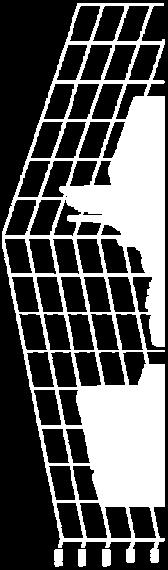

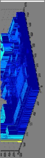


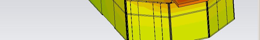
22 Enhanced 3D Near Field Scanner Optical contour detection Triangulation principle Contour detection by triangulation techniques 2 Line laser (100mW) acquisitions/sec. Compensation of optical distortion, laser-speckle, reflections, absorption etc. Line-Laser Test PCB Row data 3D Contour data 22
 in time domain (Combination of")

")

![[dbm] -30 VSA residuals [dbm] SPin [dbm] -50 SPout [dbm]](/docs-images/92/109414832/images/23-4.jpg "Input IMD3>100kHz Input IMD3<100kHz -70 10-90 -110-130")
23 Enhanced 3D Near Field Scanner Signal acquisition Vector Signal-Analyser (VSA) in time domain (Combination of mixer and ADC) IF BW = 36MHz Acquisition of amplitude and Phase Frequency range DC-6GHz High sensitivity: Noise Figure < 4dB Dynamic range in combination with SPU Dynamic range of PU + VSA in a BB range (RBW = 1 khz) -140 to 20dBm Signal Preconditioning Unit -150 Nout [dbm] Pout [dbm] IMD3 [dbm] -30 VSA residuals [dbm] SPin [dbm] -50 SPout [dbm] Input IMD3>100kHz Input IMD3<100kHz Pin [dbm]


24 Enhanced 3D Near Field Scanner Probes Balun passive probe active probe active E-field probe 100µm dipol length (Cooperation Prof. Thiede; Höchstfrequenzelektronik EIM/HFE) 24


![power [dbm] ifferential output Di](/docs-images/92/109414832/images/25-4.jpg "-160-170 -180-190 -200-210 -220 0 0.")
25 Enhanced 3D Near Field Scanner Modelling of passive Probes Differential probe response to an inpinging plane wave with 1V/m -150 t power [dbm] ifferential output Di Frequency [GHz] 25


26 Enhanced 3D Near Field Scanner Active Probes Implementation in NFS-System 26


27 Enhanced 3D Near Field Scanner Active Probes Improved Heat Dissipation Thermal distribution without heat transmission Thermal distribution with heat transmission 27


28 Enhanced 3D Near Field Scanner Multi-Probe Switch Speed up of measurement Measurement of different Probe Signals Responds at the same position Ausgang A Ausgang B Symetrierglied Ausgang A Mess- Empfänger Multi- Sondenschalter Ausgang B Digitale Steuerung Mess- Empfänger Abschirmung Abschirmung Schleife (Sensitives Element) Schleife (Sensitives Element) Conventional Probe Acquisition S 12,S 13 /db X: 1 Y: X: 1 Y: X: Y: X: Y: X: Y: X: Y: Procedure with Multi Probe -35 S S f/ GHz 28
29 Enhanced 3D Near Field Scanner Software & IT 29
30 Enhanced 3D Near Field Scanner Software & IT 30
31 Enhanced 3D Near Field Scanner Software & IT 31


32 Enhanced 3D Near Field Scanner Software & IT Controlled by 2 PC-Workstation optimised data base for near field measurements Projection and administration of measurement Configuration of measurement problem Analyse and visualisation Secure handling & reliability of system IEEE488.2-Interface for embedding ext. measurement devices in test setup Matlab-Interface Commercial software- development and support by 32
33 Conclusion and Outlook Near field scanning is an new and powerful measurement technique for new potential of analyse Emission test Immunity test Vector near field scanning with aut. contour detection open up more advantage as other systems on the market Determination of the real field indicator E and H Higher spatial resolution Further development of these techniques Contactless measurement of current and voltage Emulation of anechoic chamber (far field emulation) First Version available in Q1/2011 Build-up at Continental (Nuremberg) Coupling with CST µwave Studio (Import & Export of 3D field data) 33
34 Thank you for your attention! 34
Combining Near-Field Measurement and Simulation for EMC Radiation Analysis
 White Paper in conjunction with Combining Near-Field Measurement and Simulation for EMC Radiation Analysis Electronic components are required to comply with the global EMC regulations to ensure failure
EM-ISight Electromagnetic Scanning System. Since Page 1 of 6 Phone (613) Fax (613)
 Fax (613)") Since 1981 EM-ISight Electromagnetic Scanning System Page 1 of 6 EM-ISight ALSAS EM7 APREL Laboratories is a pioneer in the area of automated system solutions and is pleased to introduce EM-ISight which,
Since 1981 EM-ISight Electromagnetic Scanning System Page 1 of 6 EM-ISight ALSAS EM7 APREL Laboratories is a pioneer in the area of automated system solutions and is pleased to introduce EM-ISight which,
Test and Measurement for EMC
 Test and Measurement for EMC Bogdan Adamczyk, Ph.D., in.c.e. Professor of Engineering Director of the Electromagnetic Compatibility Center Grand Valley State University, Michigan, USA Ottawa, Canada July
Calibration and Validation for Automotive EMC
 Calibration and Validation for Automotive EMC Wolfgang Müllner Patrick Preiner Alexander Kriz Seibersdorf Labor GmbH 2444 Seibersdorf, Austria http://rf.seibersdorf-laboratories.at rf@seibersdorf-laboratories.at
EMC/EMI MEASURING INSTRUMENTS & ACCESSORIES SHORT-FORM CATALOG 2011
 EMC/EMI MEASURING INSTRUMENTS & ACCESSORIES SHORT-FORM CATALOG 2011 All-in-one Digital EMI Analyzer 10 Hz - 3 GHz PMM 9010/30P EMI Analyzer 10 Hz - 3 GHz Our trek started in a small laboratory over 25
Course Introduction Purpose Objectives Content Learning Time
 Course Introduction Purpose This course discusses techniques for analyzing and eliminating noise in microcontroller (MCU) and microprocessor (MPU) based embedded systems. Objectives Learn about a method
An Introduction to EMC Testing (what can be done with scopes) Vincent Lascoste EMC Product Manager - RSF
 Vincent Lascoste EMC Product Manager - RSF") An Introduction to EMC Testing (what can be done with scopes) Vincent Lascoste EMC Product Manager - RSF Definition of ElectroMagnetic Compatibility (EMC) EMC is defined as: "The ability of devices and
An Introduction to EMC Testing (what can be done with scopes) Vincent Lascoste EMC Product Manager - RSF Definition of ElectroMagnetic Compatibility (EMC) EMC is defined as: "The ability of devices and
EMC Near-field Probes + Wideband Amplifier
 1 Introduction The H20, H10, H5 and E5 are magnetic field (H) and electric field (E) probes for radiated emissions EMC precompliance measurements. The probes are used in the near field of sources of electromagnetic
Measurement Environment Influence Compensation to Reproduce Anechoic Chamber Measurements with Near Field Scanning
 Measurement Environment Influence Compensation to Reproduce Anechoic Chamber Measurements with Near Field Scanning Denis Rinas, Alexander Zeichner, Stephan Frei TU Dortmund University Dortmund, Germany
4GHz / 6GHz Radiation Measurement System
 4GHz / 6GHz Radiation Measurement System The MegiQ Radiation Measurement System (RMS) is a compact test system that performs 3-axis radiation pattern measurement in non-anechoic spaces. With a frequency
ETS Lindgren Anechoic Chamber
 ETS Lindgren Anechoic Chamber Provides an electromagnetically quiet environment for measuring the radiating properties of a device-undertest Enclosed by an external metallic shielding to provide isolation
Todd Hubing. Clemson University. Cabin Environment Communication System. Controls Airbag Entertainment Systems Deployment
 Automotive Component Measurements for Determining Vehicle-Level Radiated Emissions Todd Hubing Michelin Professor of Vehicular Electronics Clemson University Automobiles are Complex Electronic Systems
YRS01 York Reference Source
 York Reference Source York Reference Source The YRS01 is a multi-mode reference source capable of producing a broadband noise or comb output up to 1GHz. Selectable noise or comb output - Flexibility across
T- DualScan. StarLab
 T- DualScan StarLab StarLab is the ultimate tool for antenna pattern measurements in laboratories and production environments where space is limited, cost is critical, and the flexibility of a portable
Alternative Radiated Emission Test Methods Progress Achieved in IND60 Project
 Alternative Radiated Emission Test Methods Progress Achieved in IND60 Project Project EMRP IND60: Improved EMC test methods in industrial environments Mohammed Salhi 05-09 September 2016 Wroclaw, Poland
Practical Considerations for Radiated Immunities Measurement using ETS-Lindgren EMC Probes
 Practical Considerations for Radiated Immunities Measurement using ETS-Lindgren EMC Probes Detectors/Modulated Field ETS-Lindgren EMC probes (HI-6022/6122, HI-6005/6105, and HI-6053/6153) use diode detectors
Characterization of Integrated Circuits Electromagnetic Emission with IEC
 Characterization of Integrated Circuits Electromagnetic Emission with IEC 61967-4 Bernd Deutschmann austriamicrosystems AG A-8141 Unterpremstätten, Austria bernd.deutschmann@ieee.org Gunter Winkler University
Software. Equipment. Add-ons. Accessories. Services
 T- DualScan FScan FScan is a vertical near-field planar scanner system that is a perfect solution for antenna measurement applications where a phased array, high gain, or reflector antenna is under evaluation.
Future In Radiated Immunity Testing
 Future In Radiated Immunity Testing Flynn Lawrence Flynn Lawrence is an Applications Engineer for AR RF/Microwave Instrumentation. At AR, Flynn is actively engaged in new application and product development
Utilizzo del Time Domain per misure EMI
 Utilizzo del Time Domain per misure EMI Roberto Sacchi Measurement Expert Manager - Europe 7 Giugno 2017 Compliance EMI receiver requirements (CISPR 16-1-1 ) range 9 khz - 18 GHz: A normal +/- 2 db absolute
EMC/EMI MEASURING INSTRUMENTS & ACCESSORIES SHORT-FORM CATALOG 2009
 EMC/EMI MEASURING INSTRUMENTS & ACCESSORIES SHORT-FORM CATALOG 2009 Our trek started in a small laboratory over 25 years ago. Since then, we ve been focused on making EMC measurements easier and the measuring
Advanced Test Equipment Rentals ATEC (2832) CNE III Comparison Noise Emitter
 CNE III Comparison Noise Emitter") Established 1981 Advanced Test Equipment Rentals www.atecorp.com 800-404-ATEC (2832) CNE III Comparison Noise Emitter Product Technical Information CNE III Comparison Noise Emitter The industry standard
Established 1981 Advanced Test Equipment Rentals www.atecorp.com 800-404-ATEC (2832) CNE III Comparison Noise Emitter Product Technical Information CNE III Comparison Noise Emitter The industry standard
Todd H. Hubing Michelin Professor of Vehicular Electronics Clemson University
 Essential New Tools for EMC Diagnostics and Testing Todd H. Hubing Michelin Professor of Vehicular Electronics Clemson University Where is Clemson University? Clemson, South Carolina, USA Santa Clara Valley
NEAR FIELD MEASURING MEASURING SET-UP. LANGER E M V - T e c h n i k
 MEASURING SET-UP NEAR FIELD MEASURING The measurement of near fields to 6 GHz directly on electronic modules aids in the reduction of disturbance emission. Near field probes measurement setup-0513pe 2
Near-Field Scanning. Searching for Root Causes
 Near-Field Scanning Searching for Root Causes Feb. 06, 2018 Outline Susceptibility Scanning Conducted susceptibility: where does ESD current go? Near-field effects of electrostatic discharge events Emission
EMC Back to Basics. Matthew Carter EMC Product Support Engineer Agilent Technologies Inc. April 16, 2014
 EMC Back to Basics Matthew Carter EMC Product Support Engineer Agilent Technologies Inc. April 16, 2014 Agilent Technologies, Inc. 2014 Agenda EMC Back to Basics Overview What is Electromagnetic Compatibility?
Test sites for EMC measurements
 Test sites for EMC measurements EMV Fachtagung 21. Januar 2014 Christophe Perrenoud www.montenaemc.ch montena emc Route de Montena 75 CH - 1728 Rossens Tel. +41 26 411 93 33 Fax +41 26 411 93 30 office.emc@montenaemc.ch
Electromagnetic Compatibility
 Electromagnetic Compatibility Introduction to EMC International Standards Measurement Setups Emissions Applications for Switch-Mode Power Supplies Filters 1 What is EMC? A system is electromagnetic compatible
GTEM cell simplifies EMC test
 GTEM cell simplifies EMC test Check the EMC performance of your designs in the lab with a GTEM cell and a spectrum analyzer. James P. Muccioli, Jastech EMC Consulting, Farmington Hills, MI Anthony A. Anthony
Semi Anechoic Chamber (SAC)
") 1 of 9 Semi Anechoic Chamber (SAC) Approximate Dimensions of 3m Semi Anechoic Chamber (SAC) Length: 10m Width: 9m Height: 9m Frequency range of Semi Anechoic Chamber: 9 KHz to 40 GHz Emission test (EMI):
1 of 9 Semi Anechoic Chamber (SAC) Approximate Dimensions of 3m Semi Anechoic Chamber (SAC) Length: 10m Width: 9m Height: 9m Frequency range of Semi Anechoic Chamber: 9 KHz to 40 GHz Emission test (EMI):
GTEM cells. Emissions and immunity testing in a single, shielded environment
 GTEM cells Emissions and immunity testing in a single, shielded environment GTEM cells Emissions and immunity testing in a single, shielded environment Function A GTEM (Gigahertz Transverse Electro Magnetic)
AN-1011 APPLICATION NOTE
 AN-111 APPLICATION NOTE One Technology Way P.O. Box 916 Norwood, MA 262-916, U.S.A. Tel: 781.329.47 Fax: 781.461.3113 www.analog.com EMC Protection of the AD715 by Holger Grothe and Mary McCarthy INTRODUCTION
EXHIBIT 7: MEASUREMENT PROCEDURES Pursuant 47 CFR 2.947
 EXHIBIT 7: MEASUREMENT PROCEDURES Pursuant 47 CFR 2.947 7.1 RF Power -- Pursuant to 47 CFR 2.947(c) Method of Conducted Output Power Measurement: Adaptation of TIA/EIA-603-A clause 2.2.1 for Pulsed Measurements
Effectively Using the EM 6992 Near Field Probe Kit to Troubleshoot EMI Issues
 Effectively Using the EM 6992 Near Field Probe Kit to Troubleshoot EMI Issues Introduction The EM 6992 Probe Kit includes three magnetic (H) field and two electric (E) field passive, near field probes
Novel Modeling Strategy for a BCI set-up applied in an Automotive Application
 Novel Modeling Strategy for a BCI set-up applied in an Automotive Application An industrial way to use EM simulation tools to help Hardware and ASIC designers to improve their designs for immunity tests.
EVALUATION OF THE NEAR-FIELD INJECTION METHOD AT INTEGRATED CIRCUIT LEVEL
 1 EVALUATION OF THE NEAR-FIELD INJECTION METHOD AT INTEGRATED CIRCUIT LEVEL A. Boyer 1,2, B. Vrignon 3, J. Shepherd 3, M. Cavarroc 1,2 1 CNRS, LAAS, 7 avenue du colonel Roche, F-31400 Toulouse, France
Spectrum Analyzers 2680 Series Features & benefits
 Data Sheet Features & benefits n Frequency range: 9 khz to 2.1 or 3.2 GHz n High Sensitivity -161 dbm/hz displayed average noise level (DANL) n Low phase noise of -98 dbc/hz @ 10 khz offset n Low level
Electromagnetic Compatibility ( EMC )
") Electromagnetic Compatibility ( EMC ) Introduction EMC Testing 1-2 -1 Agenda System Radiated Interference Test System Conducted Interference Test 1-2 -2 System Radiated Interference Test Open-Area Test
Electromagnetic Compatibility ( EMC ) Introduction EMC Testing 1-2 -1 Agenda System Radiated Interference Test System Conducted Interference Test 1-2 -2 System Radiated Interference Test Open-Area Test
System configurations. Main features. I TScan SOLUTION FOR
 TScan TScan is a fast and ultra-accurate planar near-field scanner with the latest motor drive and encoder technologies. High acceleration of the linear motors for stepped and continuous mode operation
Immunity Test System RIS 3000 / RIS 6000 acc. to IEC/EN
 Description The setup of a radiated immunity test system can be done in the conventional way with many separate instruments or in a more comfortable and less risky way with our new EMC control unit, type
EMI Reduction on an Automotive Microcontroller
 EMI Reduction on an Automotive Microcontroller Design Automation Conference, July 26 th -31 st, 2009 Patrice JOUBERT DORIOL 1, Yamarita VILLAVICENCIO 2, Cristiano FORZAN 1, Mario ROTIGNI 1, Giovanni GRAZIOSI
EMC-scanner. HRE-series. See it before you CE it!
 EMC-scanner HRE-series See it before you CE it! Print Screen image of a scan measurement. Seeing high frequencies! Now you can SEE high frequency electro magnetic fields. The background There are high
> StarLab. Multi-purpose Antenna Measurement Multi-protocol Antenna Development Linear Array Antenna Measurement OTA Testing
 TECHNOLOGY Near-field / Spherical Near-field / Cylindrical SOLUTIONS FOR Multi-purpose Antenna Measurement Multi-protocol Antenna Development Linear Array Antenna Measurement OTA Testing 18 StarLab: a
Sub-millimeter Wave Planar Near-field Antenna Testing
 Sub-millimeter Wave Planar Near-field Antenna Testing Daniёl Janse van Rensburg 1, Greg Hindman 2 # Nearfield Systems Inc, 1973 Magellan Drive, Torrance, CA, 952-114, USA 1 drensburg@nearfield.com 2 ghindman@nearfield.com
A Complete Simulation of a Radiated Emission Test according to IEC
 34 PIERS Proceedings, August 27-30, Prague, Czech Republic, 2007 A Complete Simulation of a Radiated Emission Test according to IEC 61000-4-20 X. T. I Ngu, A. Nothofer, D. W. P. Thomas, and C. Christopoulos
Predicting Module Level RF Emissions from IC Emissions Measurements using a 1 GHz TEM or GTEM Cell A Review of Related Published Technical Papers 1
 Predicting Module Level RF Emissions from IC Emissions Measurements using a 1 GHz TEM or GTEM Cell A Review of Related Published Technical Papers 1 Jame P. Muccioli, Jastech EMC Consulting, LLC, P.O. Box
CHAPTER 6 EMI EMC MEASUREMENTS AND STANDARDS FOR TRACKED VEHICLES (MIL APPLICATION)
") 147 CHAPTER 6 EMI EMC MEASUREMENTS AND STANDARDS FOR TRACKED VEHICLES (MIL APPLICATION) 6.1 INTRODUCTION The electrical and electronic devices, circuits and systems are capable of emitting the electromagnetic
147 CHAPTER 6 EMI EMC MEASUREMENTS AND STANDARDS FOR TRACKED VEHICLES (MIL APPLICATION) 6.1 INTRODUCTION The electrical and electronic devices, circuits and systems are capable of emitting the electromagnetic
7. EMV Fachtagung. EMV-gerechtes Filterdesign. 23. April 2009, TU-Graz. Dr. Gunter Winkler (TU Graz) Dr. Bernd Deutschmann (Infineon Technologies AG)
 Dr. Bernd Deutschmann (Infineon Technologies AG)") 7. EMV Fachtagung 23. April 2009, TU-Graz EMV-gerechtes Filterdesign Dr. Gunter Winkler (TU Graz) Dr. Bernd Deutschmann (Infineon Technologies AG) Page 1 Agenda Filter design basics Filter Attenuation
7. EMV Fachtagung 23. April 2009, TU-Graz EMV-gerechtes Filterdesign Dr. Gunter Winkler (TU Graz) Dr. Bernd Deutschmann (Infineon Technologies AG) Page 1 Agenda Filter design basics Filter Attenuation
Technology in Balance
 Technology in Balance A G1 G2 B Basic Structure Comparison Regular capacitors have two plates or electrodes surrounded by a dielectric material. There is capacitance between the two conductive plates within
COMPRION Design Validation. Solution for Visualizing and Analyzing NFC Operating Volumes
 COMPRION Design Validation Solution for Visualizing and Analyzing NFC Operating Volumes Measurement and Analysis of Contactless Interfaces with Design Validation Center The increasing availability of day-to-day
Electromagnetic Field Measurement System
 Electromagnetic Field Measurement System Electromagnetic Field Measurement System Magnetic Near Field Probes Low-frequency (Active Probes) Low-frequency, High-current, Wideband High-frequency (GHz), Wideband
SPECIFICATION. Specification No : PA A-02. Description : 880~960Mhz, 1710~2170 MHz, 0dB Gain Size: 31mm *6 mm *3.
 SPECIFICATION Product Name : Triband GSM + UMTS/WCDMA Dielectric Monopole Antenna (* Quadband GSM achievable with appropriate matching circuit) Specification No : PA-880-2170-00-31-A-02 Part No. : PA-23
µwavelab Microwave Laboratory DIMES University of Calabria via P. Bucci, Cubo 41D Scientific Head: Prof. Giuseppe Di Massa
 0 µwavelab Microwave Laboratory DIMES University of Calabria via P. Bucci, Cubo 41D Scientific Head: Prof. Giuseppe Di Massa µwavelab The Microwave Laboratory (μwavelab) of the University of Calabria is
Localization and Identifying EMC interference Sources of a Microwave Transmission Module
 Localization and Identifying EMC interference Sources of a Microwave Transmission Module Ph. Descamps 1, G. Ngamani-Njomkoue 2, D. Pasquet 1, C. Tolant 2, D. Lesénéchal 1 and P. Eudeline 2 1 LaMIPS, Laboratoire
Debugging EMI Using a Digital Oscilloscope. Dave Rishavy Product Manager - Oscilloscopes
 Debugging EMI Using a Digital Oscilloscope Dave Rishavy Product Manager - Oscilloscopes 06/2009 Nov 2010 Fundamentals Scope Seminar of DSOs Signal Fidelity 1 1 1 Debugging EMI Using a Digital Oscilloscope
CONDUCTED RF EQUIPMENT POWER AMPLIFIERS. Practical RF Immunity System Design Considerations
 CONDUCTED RF EQUIPMENT POWER AMPLIFIERS Practical RF Immunity System Design Considerations 1 Designing a System Key considerations are the amplifier and antenna combination Determining what Power Amplifier
West Michigan IEEE EMC Chapter Meeting
 West Michigan IEEE EMC Chapter Meeting Intertek On-site Demonstration- Dale Wine 9.27.12 1 Global Network: Intertek Group Countries Locations Staff 110+ 1000+ 30,000+ Floated May 2002 LSE: ITRK (4.5 GBP)
Advanced Test Equipment Rentals ATEC (2832)
") Established 1981 Advanced Test Equipment Rentals www.atecorp.com 800-404-ATEC (2832) R3000 EMI TEST RECEIVERS Fully IF digital EMI Receivers family for measurement of electromagnetic interference from
Established 1981 Advanced Test Equipment Rentals www.atecorp.com 800-404-ATEC (2832) R3000 EMI TEST RECEIVERS Fully IF digital EMI Receivers family for measurement of electromagnetic interference from
LCIS, 50 rue de Laffemas, BP 54, Valence Cedex 09, France
 Smail.tedjini@grenoble-inp.fr LCIS, 50 rue de Laffemas, BP 54, 26902 Valence Cedex 09, France http://lcis.grenoble-inp.fr Slide 1 Outline Motivation Previous Works Principle of the method in this work
Saturation of Active Loop Antennas
 Saturation of Active Loop Antennas Alexander Kriz EMC and Optics Seibersdorf Laboratories 2444 Seibersdorf, Austria Abstract The EMC community is working towards shorter test distances for radiated emission
System configurations. Main features I SG 64 SOLUTION FOR
 T- DualScan SG 64 The most accurate solution for testing antennas and wireless devices: SG 64 has been developed to measure stand alone antennas or antennas integrated in subsystems. It is also ideal for
Chapter 12 Digital Circuit Radiation. Electromagnetic Compatibility Engineering. by Henry W. Ott
 Chapter 12 Digital Circuit Radiation Electromagnetic Compatibility Engineering by Henry W. Ott Forward Emission control should be treated as a design problem from the start, it should receive the necessary
TEST & MEASURING INSTRUMENTS. Analyzer. (4 Ports) 4 Ports
 4 Ports") TEST & MEASURING INSTRUMENTS Analyzer (4 Ports) 4 Ports Key Features Frequrncy Range : 100kHz ~ 8GHz, 16 Parameters support (S11 ~ S44) Measurement time per point : 100us per point Wide Output Power Range
TEST & MEASURING INSTRUMENTS Analyzer (4 Ports) 4 Ports Key Features Frequrncy Range : 100kHz ~ 8GHz, 16 Parameters support (S11 ~ S44) Measurement time per point : 100us per point Wide Output Power Range
Overview of EMC Regulations and Testing. Prof. Tzong-Lin Wu Department of Electrical Engineering National Taiwan University
 Overview of EMC Regulations and Testing Prof. Tzong-Lin Wu Department of Electrical Engineering National Taiwan University What is EMC Electro-Magnetic Compatibility ( 電磁相容 ) EMC EMI (Interference) Conducted
Transient calibration of electric field sensors
 Transient calibration of electric field sensors M D Judd University of Strathclyde Glasgow, UK Abstract An electric field sensor calibration system that operates in the time-domain is described and its
A GTEM BEST PRACTICE GUIDE APPLYING IEC TO THE USE OF GTEM CELLS
 - 27-39 H1 A BEST PRACTICE GUIDE APPLYING IEC 61-4-2 TO THE USE OF CELLS A. Nothofer, M.J. Alexander, National Physical Laboratory, Teddington, UK, D. Bozec, D. Welsh, L. Dawson, L. McCormack, A.C. Marvin,
Ultra-wideband antennas. S. Sczyslo, G. Armbrecht, H. Thye, S. Dortmund and T. Kaiser
 On the determination of the impulse response of Ultra-wideband antennas S. Sczyslo, G. Armbrecht, H. Thye, S. Dortmund and T. Kaiser Motivation Each path of the impulse response between two antennas can
E M C T E S T Y O U R SOURCE FOR TOP Q U A L I T Y TEST EQUIPMENT & E M C. w w w. h v t e c h n o l o g i e s. c o m
 E M C T E S T S O L U T I O N S P A R T N E R S F O R H V & E M C S O L U T I O N S Y O U R SOURCE FOR TOP Q U A L I T Y TEST EQUIPMENT w w w. h v t e c h n o l o g i e s. c o m Transient Immunity Generators
APPLICATIONS OF PORTABLE NEAR-FIELD ANTENNA MEASUREMENT SYSTEMS
 APPLICATIONS OF PORTABLE NEAR-FIELD ANTENNA MEASUREMENT SYSTEMS Greg Hindman Nearfield Systems Inc. 1330 E. 223rd Street Bldg. 524 Carson, CA 90745 (213) 518-4277 ABSTRACT Portable near-field measurement
Seattle & Oregon Chapters "New X2Y Filter Technology Emerges as Single Component Solution For Noise Suppression
 "New X2Y Filter Technology Emerges as Single Component Solution For Noise Suppression Presentation: approx. 60 min Introduction: A new capacitive technology introduced by X2Y Attenuators LLC, Erie, Pa.,
Pulsed S-Parameter Measurements using the ZVA network Analyzer
 Pulsed S-Parameter Measurements using the ZVA network Analyzer 1 Pulse Profile measurements ZVA Advanced Network Analyser 3 Motivation for Pulsed Measurements Typical Applications Avoid destruction of
SPECIFICATION. Product Name : 2.4GHz Band Dielectric PIFA Antenna for Bluetooth/WLAN/Zigbee Applications. Specification No : PA A-02
 SPECIFICATION Product Name : 2.4GHz Band Dielectric PIFA Antenna for Bluetooth/WLAN/Zigbee Applications Specification No : PA-2400-15-10-A-02 Part No. : PA-11 Description : 2400-2484Mhz, 1.5dB Gain Size:
INTERNATIONAL STANDARD
 INTERNATIONAL STANDARD IEC 60489-1 1983 AMENDMENT 2 1999-05 Amendment 2 Methods of measurement for radio equipment used in the mobile services Part 1: General definitions and standard conditions of measurement
Trees, vegetation, buildings etc.
 EMC Measurements Test Site Locations Open Area (Field) Test Site Obstruction Free Trees, vegetation, buildings etc. Chamber or Screened Room Smaller Equipments Attenuate external fields (about 100dB) External
Probing Techniques for Signal Performance Measurements in High Data Rate Testing
 Probing Techniques for Signal Performance Measurements in High Data Rate Testing K. Helmreich, A. Lechner Advantest Test Engineering Solutions GmbH Contents: 1 Introduction: High Data Rate Testing 2 Signal
EMC Amplifiers Going Beyond the Basics to Ensure Successful Immunity Tests
 EMC Amplifiers Going Beyond the Basics to Ensure Successful Immunity Tests Paul Denisowski, Application Engineer Broadband amplifiers are used to generate the high field strengths required by EMC radiated
Introduction to VCCI Kit Module EMI Program An approach for module level EMI quantification
 Introduction to VCCI Kit Module EMI Program An approach for module level EMI quantification Akihisa Sakurai VCCI Steering Committee Chair / IBM Hiroshi Yamane VCCI Technical Committee Chair / NTT Haruyoshi
Large E Field Generators in Semi-anechoic Chambers for Full Vehicle Immunity Testing
 Large E Field Generators in Semi-anechoic Chambers for Full Vehicle Immunity Testing Vince Rodriguez ETS-Lindgren, Inc. Abstract Several standards recommend the use of transmission line systems (TLS) as
HOW TO CHOOSE AN ANTENNA RANGE CONFIGURATION
 HOW TO CHOOSE AN ANTENNA RANGE CONFIGURATION Donnie Gray Nearfield Systems, Inc. 1330 E. 223 rd St, Bldg 524 Carson, CA 90745 (310) 518-4277 dgray@nearfield.com Abstract Choosing the proper antenna range
Investigation of Electromagnetic Field Coupling from DC-DC Buck Converters to Automobile AM/FM Antennas
 CST North American Automotive Workshop Investigation of Electromagnetic Field Coupling from DC-DC Buck Converters to Automobile AM/FM Antennas Patrick DeRoy, CST of America, Framingham, Massachusetts,
Modeling of Aperture Fields for Cavities Excited by Stochastic Current Sources
 December, 216 Microwave Review Modeling of Aperture Fields for Cavities Excited by Stochastic Current Sources Michael Haider, Biljana P. Stošić, Mohd H. Baharuddin, Nebojša S. Dončov, David W. P. Thomas,
Overview of the ATLAS Electromagnetic Compatibility Policy
 Overview of the ATLAS Electromagnetic Compatibility Policy G. Blanchot CERN, CH-1211 Geneva 23, Switzerland Georges.Blanchot@cern.ch Abstract The electromagnetic compatibility of ATLAS electronic equipments
EN 55015: 2013 Clause Pass. EN 55015: 2013 Clause Pass. EN 55015: 2013 Clause Pass
 Reference No.: WTD15S0730643E Page 2 of 42 1 Test Summary Test Item Conducted Disturbance at Mains Terminal, 9kHz to 30MHz Radiation electromagnetic disturbance, 9kHz to 30MHz Radiation Emission, 30MHz
AMPLIFIER RESEARCH... APPLICATION NOTE: 23
 AMPLIFIER RESEARCH... APPLICATION NOTE: 23 PRODUCTS THAT PROVIDE 200 V/m CW OR PM AT A DISTANCE OF 1 METER 1 The Amplifier / Antenna / Cell combinations shown in Table 1 provide various means of generating
Archived 3/18/10 USER MANUAL EMCO MODEL 3141 BICONILOG TM LOG-PERIODIC / T BOW-TIE ANTENNA Rev A 01/97
 USER MANUAL EMCO MODEL 3141 BICONILOG TM LOG-PERIODIC / T BOW-TIE ANTENNA 399236 Rev A 01/97 GENERAL DESCRIPTION The EMCO Model 3141 is the latest evolution in the popular bow-tie/log periodic combination
Vector Network Analyzers ZVB
 Specifications Version 05.00 Vector Network Analyzers ZVB September 2005 Specifications MEASUREMENT RANGE...3 MEASUREMENT SPEED...5 MEASUREMENT ACCURACY...6 EFFECTIVE SYSTEM DATA...8 TEST PORT OUTPUT...8
2009 International Zurich Symposium on Electromagnetic Compatibility
 2009 International Zurich Symposium on Electromagnetic Compatibility Module Level EMI Measurements and Estimation Workshop Predicting Module Level RF Emissions from IC Emissions Measurements using a 1
Correlation Between Measured and Simulated Parameters of a Proposed Transfer Standard
 Correlation Between Measured and Simulated Parameters of a Proposed Transfer Standard Jim Nadolny AMP Incorporated ABSTRACT Total radiated power of a device can be measured using a mode stirred chamber
How EMxpert Diagnoses Board-Level EMC Design Issues
 Application Report EMxpert July 2011 - Cédric Caudron How EMxpert Diagnoses Board-Level EMC Design Issues ABSTRACT EMxpert provides board-level design teams with world-leading fast magnetic very-near-field
The Precision Spherical Dipole Source
 The Precision Spherical Dipole Source Freedom to make accurate and repeatable measurements!! Presented by: Bruce Archambeault, Ph.D. Partner / Technical Director bruce@appliedemtech.com (AET) Mission:
EMC LAB EQUIPMENT CALIBRATION SCHEDULER
 Page 1 of 7 Purpose: To maintain a list of equipment scheduled for calibration and the test methods where is involved. Responsibility: Technical manager, EMC lab technicians Overview: The actual calibration
8GHz RF EMF Strength Meter
 8GHz RF EMF Strength Meter High Frequency measurement for EMF Monitor high frequency radiation in the 10MHz to 8GHz frequency range Features: For electromagnetic field strength measurement including mobile
ELEC 0017: ELECTROMAGNETIC COMPATIBILITY LABORATORY SESSIONS
 Academic Year 2015-2016 ELEC 0017: ELECTROMAGNETIC COMPATIBILITY LABORATORY SESSIONS V. BEAUVOIS P. BEERTEN C. GEUZAINE 1 CONTENTS: EMC laboratory session 1: EMC tests of a commercial Christmas LED light
EMC review for Belle II (Grounding & shielding plans) PXD DEPFET system
 PXD DEPFET system") EMC review for Belle II (Grounding & shielding plans) PXD DEPFET system Outline 1. Introduction 2. Grounding strategy Implementation aspects 3. Noise emission issues Test plans 4. Noise immunity issues
EMC review for Belle II (Grounding & shielding plans) PXD DEPFET system Outline 1. Introduction 2. Grounding strategy Implementation aspects 3. Noise emission issues Test plans 4. Noise immunity issues
The Survey of Electromagnetic Environment near RF Transmitters
 The Survey of Electromagnetic Environment near RF Transmitters Valeriu David 1, Alexandru Salceanu, Mihai Cretu 3, Eduard Lunca 4 1 "Gh. Asachi" Technical University, Iasi, Faculty of Electrical Engineering,
System description 4. SERVICES ONSITE INSTALLATION AND TRAINING SYSTEM ACCEPTANCE MAINTENANCE... 7
 Ultra Wide Band test setup System description 1. UWB TEST SYSTEM DESCRIPTION... 2 2. SYSTEM MONITORING... 5 3. OTHER MEASUREMENT SYSTEMS & ACCESSORIES... 6 3.1 OSCILLOSCOPE & SHIELDED ENCLOSURE... 6 3.2
REVERBERATION CHAMBER FOR EMI TESTING
 1 REVERBERATION CHAMBER FOR EMI TESTING INTRODUCTION EMI Testing 1. Whether a product is intended for military, industrial, commercial or residential use, while it must perform its intended function in
LANGER EMV-TECHNIK. Operating Instructions. A 100 / A 200 / A 300 Optical Fibre Probe
 LANGER EMV-TECHNIK Operating Instructions A 100 / A 200 / A 300 Optical Fibre Probe Contents: Page 1. Usage 2 2. Function 4 3. Operation 4 4. Safety instructions 5 5. Technical data 6 6. Scope of delivery
SEMS SHIELDING EFFECTIVENESS MEASUREMENT SYSTEM IN MRI AND SHIELDED ENVIRONMENT. ELECTRIC AND MAGNETIC FIELD FROM 10 khz TO 300 MHz*
 SEMS SHIELDING EFFECTIVENESS MEASUREMENT SYSTEM IN MRI AND SHIELDED ENVIRONMENT ELECTRIC AND MAGNETIC FIELD FROM 10 khz TO 300 MHz* MRI Shielding Environment (Magnetic Resonance Imaging) Shielded and anechoic
EMF Compliance Assessments of 5G Devices
 EMF Compliance Assessments of 5G Devices Serge Pfeifer, IT IS Foundation Esra Neufeld, IT IS Foundation Eduardo Carrasco, IT IS Foundation Andreas Christ, IT IS Foundation Myles Capstick, IT IS Foundation