OPERATION & MAINTENANCE MANUAL FOR U-9353 UPCONVERTER JANUARY 2001 CUSTOMER
|
|
|
- Christina Hodges
- 5 years ago
- Views:
Transcription
1 Ref.: XXXXX OPERATION & MAINTENANCE MANUAL FOR U-9353 UPCONVERTER JANUARY 2001 CUSTOMER MAXXXXXU E Rev.A
2 The suffix XXXXX following part numbers in this manual is a unique number assigned at time of order. This number should be referred to in all correspondence and all referrals to spare parts. The reference number is XXXXX. The AC voltage has been set to XXX VAC. - ii -
3 TABLE OF CONTENTS SECTION 1 INTRODUCTION Para. Page 1.1 GENERAL DESCRIPTION PHYSICAL FUNCTIONAL EQUIPMENT CHARACTERISTICS PHYSICAL FUNCTIONAL EQUIPMENT REQUIRED EQUIPMENT SUPPLIED EQUIPMENT REQUIRED BUT NOT SUPPLIED SECTION 2 INSTALLATION 2.1 UNPACKING, STORAGE, RESHIPMENT MOUNTING TURN-ON PROCEDURE SECTION 3 OPERATION 3.1 INTRODUCTION CONTROLS EXTERNAL CONTROLS INTERNAL CONTROLS OPERATING PROCEDURE LOCAL OPERATION Set Frequency Channel Memory iii -
4 TABLE OF CONTENTS (Cont.) SECTION 3 OPERATION Para. Page REMOTE OPERATION RS422/RS485 Protocol Data Transfer Header Byte Device Address Byte Command/Error Codes Parameter Bytes Trailer Byte Checksum Byte Command Codes Frequency Code = F Mute Code = M Status All Code = A Status Faults Code =? (Optional) Device Address/Baud Rate Selection Programming Examples Remote Interface Connector RS422/485 Bus Termination Contact Closure Control IEEE-488 Control Device Address/Service Request Enable Data Input Messages Frequency Set Mute Set/Store Frequency in Channel nn Recall Frequency from Channel nn Data Format Frequency Format Status Faults Format Status All Format Channel Format Service Request EMERGENCY OPERATION SHUTDOWN PROCEDURE iv -
5 TABLE OF CONTENTS (Cont.) SECTION 4 PRINCIPLES OF OPERATION Para. Page 4.1 INTRODUCTION FUNCTIONAL DESCRIPTION SUBSYSTEMS AND COMPONENTS FUNCTIONAL DESCRIPTION SIGNAL PATH Upconverter Module (A2A1) Filter, Isolator (A2A2, A2A3) Mixer, Second Conversion (A2A4) Output Isolators, Filter (A2A5, A2A6, A2A7) Option 11 - Output Amplifier LOCAL OSCILLATOR MHz Reference (A3A1) MHz Phase Locked Source (A3A2) Second Local Oscillator Frequency Synthesizer (A3A4) Second Local Oscillator Chain (A3A5 to A3A9) CONVERTER CONTROLLER POWER SUPPLY, LOW PASS FILTER v -
6 TABLE OF CONTENTS (Cont.) SECTION 5 MAINTENANCE Para. Page 5.1 INTRODUCTION PREVENTIVE MAINTENANCE DC VOLTAGE GAIN OF THE CONVERTER FREQUENCY MEASUREMENT LOCAL OSCILLATOR PHASE LOCK TEST POINT (Phase Voltage) CORRECTIVE MAINTENANCE POWER SUPPLY MALFUNCTION LOCAL OSCILLATOR CONVERTER, SIGNAL CHAIN SECTION 6 DIAGRAMS 6.1 INTRODUCTION vi -
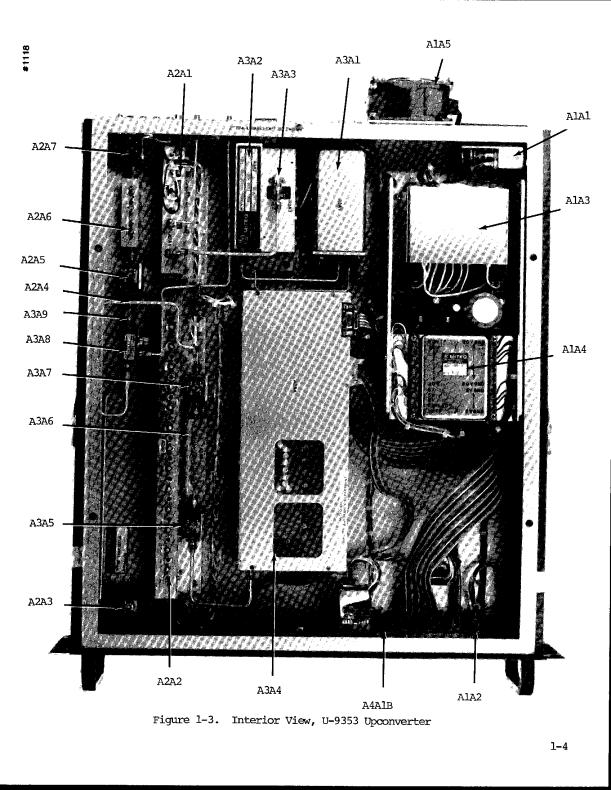
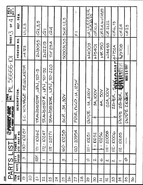
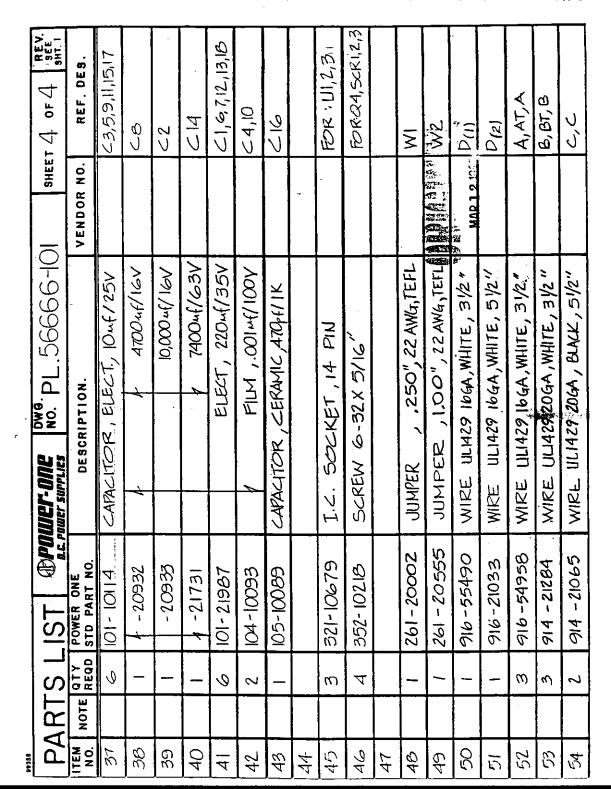
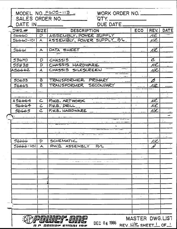
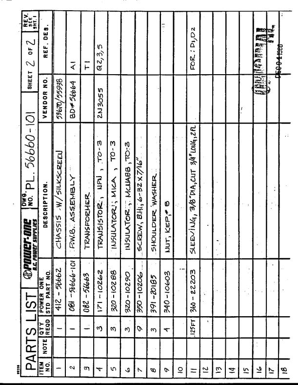
7 TABLE OF CONTENTS (Cont.) Number TABLES Page 1-1 Equipment Supplied Test Equipment Required But Not Supplied External Connections Parts List - U-9353 Upconverter List of Diagrams FIGURES 1-1 Front View, U-9353 Upconverter Rear View, U-9353 Upconverter Interior View, U-9353 Upconverter Front Panel Layout, 9300 Series Converter RS422/RS485 Bus Termination Jumpers, 9300 Series Converter Block Diagram, U-9353 Upconverter Block Diagram, 960 MHz Phase Lock Source (A3A2) Test Setup for Gain, Gain Ripple and Frequency Response Measurement DIAGRAMS 6-1 Wiring Diagram Schematic Diagram, Converter Controller 9300 Series Assembly Diagram, Converter Controller 9300 Series 6-14 APPENDIX A Power Supply Manual (FS05-113) vii -
8 SECTION 1 INTRODUCTION 1.1 GENERAL DESCRIPTION PHYSICAL The physical configuration of the U-9353 Upconverter is shown in Figures 1-1 through 1-3. The main chassis houses all RF components, control circuitry and power supplies. The converter chassis is 19" x 22" x 3.5" panel height. Slides are provided for mounting in a standard 19" (EIA) equipment rack. The following items are found on the front of the converter: A. On/Off Power Switch (A1A2) B. LO Out-of-Lock LEDs C. Memory, Store Key D. Memory, Recall Key E. Display F. Gain Adjustment Potentiometer G. Data Entry Keypad H. Remote Mode Select Key The following items are found on the rear of the converter: A. RF Input Connector (J1) B. IF Output Connector (J2) C. Summary Alarm Connector (J3) D. Remote Interface Connector (J6) E. Redundancy Switch Connector (J7) F. Address Select Switch G. AC Voltage Input H. Fuse, 2.0A for 120VAC, 1.0A for 220VAC I. Fan (A1A5) J. Ground Lug K. LO Frequency/Power Monitors L. LO Phase Lock Voltage Test Points M. DC Voltage Test Points 1-1
9
10
11
12 1.1.2 FUNCTIONAL The MITEQ 9300 Series Converter combines a state of the art communications converter with microprocessor-controlled digital circuitry to provide flexibility and convenience for the station operator. The converter translates the 70 ±20 MHz frequency band to the GHz output frequency band. Phase noise, amplitude flatness, group delay, and spurious outputs have been given optimum consideration to provide the user with a transparent frequency conversion for all video and data applications. RF frequency may be selected from the front panel in 125 khz increments. Non-volatile memory allows the operator to store up to thirty channel frequencies. Remote operation is available via the RS485 (serial) interface. The status of the converter's functions and alarms may also be read through the remote interface (optional). Device address is selectable at the rear panel. Relays are provided for summary alarm output which may be used for monitoring at a remote console and for redundant switching. AC voltage input is selectable at the rear panel (100, 120, 220, 230/240VAC). 1-5
13 1.2 EQUIPMENT CHARACTERISTICS PHYSICAL A. Weight: 30 pounds nominal B. Overall Dimensions: 19" x 22" x 3.5" panel height C. Signal Input Connector (J1): BNC female D. Signal Output Connector (J2): N female E. Summary Alarm Connector (J3): DE-9P F. Remote Interface Connector (J6) - 1. RS485/RS422: DE-9S 2. RS232: DB-25P 3. Contact Closure: DB-25S 4. GPIB: IEEE-488 receptacle G. Redundancy Switch Connector (J7): DE-9P FUNCTIONAL A. Gain, Frequency Response - 1. Input Frequency: 70 ±20 MHz 2. Output Frequency: GHz 3. Gain: 11 db nominal Gain Option No. Nominal Converter Gain (db) 11A 20 11B Amplitude Response: ±20 MHz at 0.5 db ±18 MHz at 0.4 db 5. Gain Adjustment: 6 db nominal (no options) 30 db minimum (Option 3C) 1-6
14 B. Group Delay (±18 MHz) - 1. Standard - a. Linear: 0.03 ns/mhz b. Parabolic: 0.01 ns/mhzý c. Ripple: 1 ns peak-to-peak 2. Option 5A: 1 ns peak-to-peak total group delay C. VSWR - 1. Input: 26 db return loss/75 ohms (50 ohms optional) 2. Output: 20 db return loss/50 ohms D. Third Order Intermodulation: For two inband signals at an output level of -20 dbm, intermodulation products 50 dbc minimum (Option 11A output level -10 dbm) (Option 11B output level -5 dbm) E. Spurious - 1. Dependent: -65 dbc 2. Independent: -80 dbm inband (no options) -70 dbm inband (Option 11A) -60 dbm inband (Option 11B) F. Frequency Selection: GHz in 125 khz increments 1. Channel Memories: 30 (non-volatile) G. Primary Power: Selectable at the rear panel (100, 120, 220, 230/240VAC) 1-7
15 H. Rear Panel Test Points - 1. RF LO Phase Voltage: Variable with frequency 2. IF LO Phase Voltage: 10 ±2V 3. RF LO Frequency/Power Test Point: -15 dbm minimum, MHz 4. IF LO Frequency/Power Test Point: -15 dbm minimum, 1030 MHz 5. DC Voltage Test Points: +20 ±0.5V +5.2 ±0.1V +5.2 ±0.1V I. Summary Alarm Connector (J3) Pin Designations - 1. DC Power Status - a. Normal: 1-2 open, 2-3 closed b. Fault: 1-2 closed, 2-3 open 2. Summary Alarm - a. Normal: 4-5 open, 5-6 closed DC Power Normal and Local Oscillators In-Lock and LO Level Normal (Option 8 Only) b. Alarm: 4-5 closed, 5-6 open DC Power Fault or Local Oscillator(s) Out-of-Lock or LO Level Low (Option 8 Only) J. Redundancy Switch Connector (J7) Pin Designations - 1. Normal: 1-2 open, 2-3 closed DC Power Normal and Local Oscillators In-Lock and LO Level Normal (Option 8 Only) 2. Alarm: 1-2 closed, 2-3 open DC Power Fault or Local Oscillator(s) Out-of-Lock or LO Level Low (Option 8 Only) 1-8
16
17 SECTION 2 INSTALLATION 2.1 UNPACKING, STORAGE, RESHIPMENT Carefully open the shipping container and remove the equipment. Weight of the converter is approximately 30 pounds. Inspect the equipment thoroughly and report any damage. If the equipment is to be stored, it should be wrapped in plastic and kept in a clean, dry place. If the equipment is to be reshipped for any reason, wrap in heavy plastic and ship in a heavy (275 lb. test) double-wall carton. At least three inches of a solid packing material should be used on all sides of the converter. The carton should be marked to indicate that it contains fragile electronic equipment. 2.2 MOUNTING The converter chassis is 19" x 22" x 3.5" panel height. Slides are provided for mounting in a standard 19" (EIA) equipment rack. The converter should be securely mounted. 2.3 TURN-ON PROCEDURE After mounting, make all external connections per Table 2-1. Refer to Section 1 for the physical configuration of the converter. Apply power to the converter using the front panel power On/Off switch. Allow one half hour minimum for oven warm-up in the internal crystal oscillator. All LO fault lights should be off. System is now operational. 2-1
18
19 SECTION 3 OPERATION 3.1 INTRODUCTION The following paragraphs describe the controls, adjustments and procedures for turn-on, operation, emergency operation and shut down of the converter. 3.2 CONTROLS EXTERNAL CONTROLS (Figures 1-1, 1-2 and 3-1) A. On/Off switch (A1A2) applies AC power to the converter B. Fuse (A1A1) 2.0A for 100 and 120 VAC, 1.0A for 220 and 230/240 VAC C. AC Power Selection (A1A1) Voltage input is selected using a card located below the fuse on the AC input connector. The selected voltage input is indicated on the installed card. To change the voltage input, pull the card out and replace it with the desired voltage facing out. The card can be used to set the AC input voltage to 100, 120, 220, or 230/240 VAC. D. Gain Control The front panel potentiometer provides 6 db minimum of gain control. If Option 3C is ordered the front panel potentiometer will provide a minimum of 30 db gain control. E. Data Entry Section The keyboard is used for all numeric entry into the converter. A tone will sound for data entry error. There are two keys on the keyboard in addition to the standard numeric keypad and decimal point: 1. "CL" - This key is used to clear the LCD display. 2. "ENT" - This key is used to terminate commands. 3-1
20
21 F. Remote Mode Select Switch When remote control is installed, the front panel "REMOTE" switch selects either Local (front panel) or Remote mode of operation. G. Channel Memory The converter has thirty memories for frequency settings numbered 00 to INTERNAL CONTROLS (Figure 1-3) A. Power Supply Voltage Adjustment Adjustment of the DC power supplies within the specified tolerances may be made using an insulated tuning tool (refer to Section and Appendix) after removal of the power supply cover. 3-3
22 3.3 OPERATING PROCEDURE LOCAL OPERATION (See Figure 3-1) When remote control is installed, the front panel "REMOTE" switch selects either Local (front panel) or Remote mode of operation. Depressing the "REMOTE" panel switch will place the converter in the remote operation mode. A LED on the panel will light to indicate remote mode. Commands are accepted through the rear panel remote interface connector (J6). All front panel function and data entry keys (except "REMOTE") are disabled and if pressed, will cause the error tone to sound. To return to local operation, depress the "REMOTE" panel switch again. The LED on the panel will not be lit to indicate local mode. All command inputs are from the front panel. The unit will not accept instructions through the remote interface connector (J6) but will report frequency, mode and status Set Frequency To set the frequency of the converter: A. Enter the desired frequency (in MHz) using the numbered keys and the decimal point. B. Press "ENT" Channel Memory The converter has thirty memories for frequency settings numbered 00 to 29. To store a frequency in memory: A. Enter the desired frequency (in MHz) using the numbered keys and the decimal point. B. Press "STR" and enter the memory number using the numbered keys (two digits). The "MEMORY" LED will be on during the key sequence. To recall a frequency from memory: A. Press "RCL". B. Enter the memory number using the numbered keys (two digits). The "MEMORY" LED will be on during the key sequence. 3-4
23 3.3.2 REMOTE OPERATION When remote control is installed, the front panel "REMOTE" switch selects either Local (front panel) or Remote mode of operation (see Section 3.3.1) RS422/485 Protocol All transmissions are multi-byte sequences beginning with a header byte and ending with a trailer byte and checksum byte. The transmitted bytes are all ASCII printable characters in the range of 20H to 7EH. Data transmission format is a 10 bit sequence consisting of 1 start, 7 data, 1 parity and 1 stop bit. Odd or Even parity is set from the rear panel "ADDRESS" DIP switch. All characters, including the checksum character, are checked for parity. If any character in the message has a parity, framing or overrun error, the entire message is ignored and no response is made by the converter. All messages addressed to the converter are normally acknowledged with a response message. Before sending the response message a converter configured for RS422A will check for no activity on the communication bus for a period of at least one character time. If the bus is active, the response message will be cancelled. This allows a controller to rapidly update a number of devices on the communication bus without having to wait for a response. When using this method (available only for RS422A) the following restrictions apply: - Minimum frequency update period is 100 msecs. - Multiple commands may not be sent without waiting for a response from each command. The converter continually monitors the communications bus and will accept all commands addressed to it even when in Local mode. When in Local mode, receipt of any commands other than Status All or Status Faults will be ignored and the converter will respond with an error code. 3-5
24 Data Transfer The general message format is as follows: HEADER - DEVICE ADDRESS - COMMAND/ERROR CODE - PARAMETERS (if required) - TRAILER - CHECKSUM The response time from Command to acknowledge is 100 ms. maximum. Since all bytes are ASCII printable characters, a compatible terminal may be used to control the converter or monitor traffic on the communication bus Header Byte The Header byte is 7BH, ASCII character "{" Device Address Byte The Device Address may take on the values from 40H to 5FH (32 possible addresses) Command/Error Codes Command Codes ASCII Code Character Function 46H F Frequency Set 4DH M Mute 41H A Status All 3FH? Status Faults Error Codes ASCII Code Character Function 61H a Command not recognized 62H b Illegal parameter or parameter out of range 63H c Unit in Local mode 64H d Busy 3-6
25 Parameter Bytes Parameters are numeric characters which are sent MSD first, LSD last. Non-numeric parameters such as ",", "." or values beyond the range of the converter will be rejected and cause the converter to respond will error code "b" Trailer Byte The Trailer byte is 7DH, ASCII character "}" Checksum Byte The Checksum byte is the sum modulo 95 of all message characters beginning with the header byte up to and including the trailer byte. The value 32 is subtracted from each character value before taking the modulo 95 sum. The value 32 is added to the final sum to obtain the Checksum value. All values are in decimal. Checksum = Mod [(character value - 32), 95]
26 Command Codes The following paragraphs describe each of the command codes Frequency Code = F The Frequency command requires a 7 or 8 digit parameter which sets the frequency of the converter in khz. Assuming no error conditions, the converter is immediately set to the frequency. Remote Command Sequence (8 Digit): F (7 Digit): F Converter Response: F Mute Code = M The Mute command requires no parameters. The output of the converter is muted until a Frequency command is received. Remote Command Sequence: M Converter Response: M Status All Code = A The Status All command requires no parameters. The converter responds in both Local and Remote mode with the converter frequency, remote/local status, mute status and component fault status. Remote Command: A Converter Response: AFffffffffL1Mm?abcdef A = Status All indicator F = Frequency indicator fffffff(f): 7 or 8 digit ASCII numeric character indicating frequency. MSD transmitted first, LSD last. L = Local/Remote indicator l = "0" or "1" ASCII numeric character 0 = Local 1 = Remote M = Mute indicator m = "0" or "1" ASCII numeric character 0 = Mute off 1 = Mute on? = Component Fault Status indicator a-f = "0" or "1" ASCII numeric character 0 = No fault 1 = Fault a through f indicate the status of the six component fault lines. 3-8
27 Status Faults Code =? (Optional) The Status Faults command requires no parameters. The converter responds in both Local and Remote mode with the component fault status. Remote Command:? Converter Response:?abcdef?: Component Fault Status indicator a-f: "0" or "1" ASCII numeric character 0 = No fault 1 = Fault a through f indicate the status of the six component fault lines. a Synthesizer Alarm b LOA Alarm c LOB Alarm d Power Supply Alarm e LO1 Level Detect f LO2 Level Detect 3-9
28 Device Address/Baud Rate Selection The device address is set with a DIP switch on the rear panel. S1, 2, 3, 4 and 5 select the 5 LSBs of the address in binary (switch off = "1", switch on = "0", S1 = LSB.) The two MSBs are permanently set to "10" and not available to the user. The baud rate and parity are selected with switches S6, 7 and 8 in the following code (switch off = "1", switch on = "0"). S8 S7 Baud Rate S6 Parity 0 Even 1 Odd Programming Examples The converter address is 41H (ASCII code A). The following are typical commands and responses showing the ASCII printable characters. A. Set the frequency to MHz Controller Command {AF }0 Converter Response {AF}a or possible error code {Ac}~ B. Status Faults Command - response indicates the synthesizer alarm is in a fault condition. Controller Command {A?}Z Converter Response {A?100000} 3-10
29 Remote Interface Connector RS422/485* - J6-1 Ground -3 Data Out - -5 Data In - -7 Data Out + -9 Data In + * For RS485 two wire party line operation DATA IN + must be externally wired to DATA OUT +, and DATA IN - externally wired to DATA OUT -. RS232 - J6-1 Ground -2 TX Data -3 RCV Data -4 RTS -5 CTS -7 Ground Contact Closure - J6-1 F14-2 F08-3 F05-4 F02-5 F01-6 COM -10 F06-11 F10-12 F12-13 F15-14 F16-15 F04-16 F03-17 F09-23 F07-24 F13-25 F11 IEEE IEEE-488 compatible 24 contact connector (receptacle). 3-11
30 RS422/485 Bus Termination (See Figure 3-2) Jumper selectable, 120 ohm termination resistors are connected across the DATA IN +/- and DATA OUT +/- terminals. Installing E1 places the resistor across the DATA OUT terminals and installing E2 places the resistor across the DATA IN terminals Contact Closure Control Inputs to the rear panel interface connector (J6) are continuously scanned for momentary closures. When a closure is detected the converter will tune to 1 of 16 pre-selected frequencies stored in memory locations 01 through 16. This operation requires the converter to be in remote operation modes. Momentary connection of F"nn" to COM will cause the converter to tune to the frequency stored in memory location "nn" IEEE-488 Control The 9300 Series Converter performs the basic Talker and Listener functions as specified in IEEE Standard 488. It is also capable of sending a Service Request to the IEEE-488 controller and will respond with a status word when the Serial Poll Enable message is received Device Address/Service Request Enable The device address is set with the ADDRESS DIP switch on the rear panel. S1, 2, 3, 4 and 5 select the address assignment in binary (switch off = "1", on = "0", S1 = LSB). Switch 8 enables the Service Request feature (switch off = disabled, on = enabled). S6, 7 are spares. The Service Request feature is only available in converters equipped with the Status Alarm Readout option Data Input Messages The messages to and from the converter are ASCII character strings terminated with CR, LF and EOI Frequency Set The Frequency Set message sets the converter to the specified frequency in khz and also unmutes the converter. F F (8 digit) (7 digit) 3-12
31 Data Input Messages Cont'd Mute The Mute message mutes the RF output of the converter. M Set/Store Frequency in Channel nn This message is similar to the Frequency Set message. It sets the converter to the specified frequency in khz, unmutes the converter and stores the frequency in channel memory "nn". S01F (8 digit frequency stored in Channel 01) S25F (7 digit frequency stored in Channel 25) Recall Frequency from Channel nn This message sets the converter to the frequency previously stored in channel memory "nn". It also unmutes the converter. C05 (Recall frequency stored in Channel 05) Data Format These messages determine the converter's response when it is addressed to talk by the IEEE-488 Controller. A Data Format message remains in effect until another one is received. DF is the power on default format Frequency Format Data Format Converter Response DF FffffffffLlMm F = Frequency indicator fffffff(f) = 7 or 8 digit converter frequency in khz L = Local/Remote indicator l = 0 = Local, 1 = Remote M = Mute indicator m = 0 = mute off, 1 = mute on 3-13
32 Data Input Messages Cont'd Status Faults Format Data Format Converter Response D??abcdef? = Status indicator a-f = 0 = no fault, 1 = fault a through f indicate the status of the six component fault lines a Synthesizer Alarm b LOA Alarm c LOB Alarm d Power Supply Alarm e LO1 Level Detect f LO2 Level Detect The Status Alarm readout option is required for this format Status All Format Data Format Converter Response DA FffffffffLlMm?abcdef The DA format is a combination of the DF and D? formats. The Status Alarm readout option is required Channel Format Data Format Converter Response DCnn CnnFffffffff The DCnn format returns the frequency stored in channel nn (00-29). It has no effect on the frequency output of the converter. 3-14
33 Data Input Messages Cont'd Service Request The converter will issue a service request (activate the SRQ line) when one of the status alarm lines indicate a failure. The IEEE-488 Controller responds by sending the SPE message (Serial Poll) and addresses the unit to talk. The converter responds with the following message: Bit No S2 S1 S0 The S"n" bits indicate in binary code which component fault line caused the service request (a = 0, b = 1, c = 2, etc.). The IEEE-488 Controller may perform a Serial Poll without a service request being generated by the converter (the request may have been generated from another device on the bus). In this case, the response will be the same message (the data field will be the same as the last status word sent) however, bit 6 will be at "0" EMERGENCY OPERATION In the event of a failure in converter components, refer to Section 5.3 to determine possible cause/remedies SHUTDOWN PROCEDURE The converter is completely shut down when the AC power is removed. 3-15
34
35 SECTION 4 PRINCIPLES OF OPERATION 4.1 INTRODUCTION The following paragraphs provide information on the principles of operation of the MITEQ Model U-9353 Upconverter. Overall functional operation of the system is discussed in Paragraph 4.2 and detailed principles of operation for the individual subassemblies are presented in Paragraph FUNCTIONAL DESCRIPTION The converter translates a 40 MHz frequency band at 70 MHz to the GHz output frequency band. A double conversion system is used (see Figure 4-1). The input signal is fed to a well-matched upconverter module. If Option 2B is ordered, a coupled output port is included in the module to provide an IF test point at the rear panel of the converter. If the converter is ordered with Option 5, the signal passes through a group delay equalizer which is included in the module. The input signal is fed through a PIN diode attenuator, providing gain control for the system, amplified and fed to a mixer which converts the input signal to the second IF frequency. The signal is then amplified again and output from the module. The output of the converter module is fed to a filter which rejects out-of-band signals resulting from the first conversion, including rejection of local oscillator signal. The signal is then fed to the second mixer which translates the signal frequency to the output frequency band. The output of the second mixer is filtered for rejection of outof-band signals. An optional output amplifier (Option 11) may be used to increase the output level of the converter. The reference source for the local oscillator chains is a dual output high stability oven-controlled crystal oscillator at 5 MHz. The first local oscillator is a phase locked source which is locked to the 5 MHz reference. The second local oscillator is a synthesized frequency source which is locked to the 5 MHz reference. 4-1
36
37
38
39 4.3 SUBSYSTEMS AND COMPONENTS FUNCTIONAL DESCRIPTION SIGNAL PATH Upconverter Module (A2A1) Part Number: UMD XXXXX Description: Upconverter Module Function: Provide a well matched system input, frequency translation, gain and gain control. Design: Integrated assembly Specifications - A. Frequency - 1. Input: MHz 2. Output: 1100 ±20 MHz 3. LO: 1030 MHz at +10 dbm B. Gain: 19 db nominal C. Input VSWR: 26 db/75 ohms (50 ohms with Option 15) D. Output VSWR: 23 db/50 ohms E. Power Output (1 db Compression): +6 dbm F. DC Voltage: +20 volts G. Gain Control: 6 db minimum (30 db with Option 3C) H. IF Monitor Output (Option 2B): I. Local Oscillator Monitor Output: -20 dbc nominal -20 dbc nominal J. Connectors - 1. Input: BNC female 2. LO/Output: SMA female 3. DC: Solder filter 4-5
40 Filter, Isolator (A2A2, A2A3) A2A2 - A2A3 - Description: Filter Part Number: FLT XXXXX Function: IF passband, out-of-band rejection Design: Eight pole rod combline bandpass Specifications - A. Frequency: 1100 ±20 MHz B. Insertion Loss: 1.0 db C. Input/Output VSWR: 25 db D. Parabolic Group Delay: 4 nsec ±20 MHz E. Rejection: 75 db ±70 MHz Description: Isolator Part Number: Specifications - A. Frequency: 1100 ±50 MHz B. Insertion Loss: 0.5 db C. Input/Output VSWR: 1.1:1 D. Isolation: 23 db minimum E. Connectors: SMA female 4-6
41 Mixer, Second Conversion (A2A4) Part Number: M XXXXX Function: Frequency translation Design: Double balanced Specifications - A. Input Frequency: 1100 ±20 MHz B. Output Frequency: GHz C. LO Frequency: MHz D. Conversion Loss: 6.5 db nominal E. LO Power: +10 dbm F. Isolation - 1. LO/Output: 20 db 2. LO/Input: 20 db G. Power Output (1 db Compression): -5 dbm minimum H. Connectors - 1. Input: SMA male 2. Output: SMA male 3. LO: SMA female 4-7
42 Output Isolators, Filter (A2A5, A2A6, A2A7) A2A5, A2A7 - A2A6 - Description: Isolator Part Number: , Specifications - A. Frequency: GHz B. Insertion Loss: 0.25 db C. Input/Output VSWR: 1.15:1 D. Isolation: 23 db minimum E. Connectors: SMA female input N female output ( ) SMA female output( ) Description: Filter Part Number: FLT XXXXX Function: Rejection of out-of-band mixer products Design: Six pole combline Specifications - A. Frequency: GHz B. Insertion Loss: 0.4 db C. Flatness: 0.2 db peak-to-peak D. VSWR Input/Output: 1.2:1 E. Connectors - 1. Input: SMA male 2. Output: SMA male 4-8
43 Option 11 - Output Amplifier Description: Amplifier Part Number: XXXXX (Option 11A) XXXXX (Option 11B) Function: Increase system output level Design: GaAs FET Specifications - A. Frequency: GHz B. Gain - 1. Option 11A: 10 db nominal 2. Option 11B: 20 db nominal C. Input/Output VSWR: 2:1 D. Power Output (1 db Compression): +13 dbm E. DC Voltage: +20 volts F. Connectors - 1. Input: SMA male 2. Output: SMA male 3. DC: Solder filter An additional isolator may be inserted between the output filter and the Option 11 output amplifier. 4-9
44 4.3.2 LOCAL OSCILLATOR MHz Reference (A3A1) Part Number: XXXXX The dual output 5 MHz crystal oscillator is a highly stable precision crystal oscillator enclosed in a proportionallycontrolled oven housing. The specifications of the crystal oscillator are: A. Frequency: MHz B. Power Outputs: 0±3 dbm C. DC Power - 1. Warm-Up: +20V/150 ma 2. Normal: +20V/70 ma stabilized at 25 C D. Oven Stabilization Time: 20 minutes (25 C) E. Connectors - 1. RF: SMA female 2. DC: Solder filter Refer to the index for description and data sheets for higher stability reference sources when installed (Option 10). 4-10
45 MHz Phase Lock Source (A3A2) Part Number: DPLO P-XXXXX Alternate Part Number: XXXXX The phase lock source consists of: 1. Fundamental VTO (1030 MHz) 2. Frequency divider ( 206) 3. Phase detector 4. Phase lock alarm circuit A functional block diagram is shown in Figure 4-2. A sample of the VTO is directed through the frequency divider and then to the phase detector. The input reference frequency is also fed to the phase detector. When the input reference frequency and divided VTO frequency differ only in phase, the phase detector output is a DC voltage proportional to the phase difference between these two signals. A frequency difference between the two signals results in a sweep voltage which is applied to the voltage-tuned capacitor of the VTO. As the VTO is being swept through its frequency range, comparison of frequency is made in the phase detector. When the divided VTO frequency is at the same frequency as the input reference, the sweep is disabled and the VTO is locked to the input reference. The specifications for the phase lock source are: A. Frequency Output: 1030 MHz B. Frequency Input: 5 MHz C. Power Output: +12 dbm nominal D. Power Input: 0±3 dbm E. DC Power: +20V at 300 ma, +5V at 500 ma F. Phase Voltage TP: 10 ±2V "in-lock", +1 or +19V "out-of-lock" G. Connectors - 1. RF: SMA female 2. DC: Solder filter A fixed attenuator follows the phase lock source and is used to provide level adjustment. 4-11
46
47 Second Local Oscillator Frequency Synthesizer (A3A4) The microwave frequency synthesizer incorporates multiple loop, digital phase locking techniques to produce an RF output frequency in steps of 125 khz. Phase lock loop bandwidths are adjusted for best overall phase noise performance. Due to the complexity of the microwave synthesizer, it is recommended that all service be referred to the factory. The specifications for the synthesized source are: A. Frequency Output: MHz B. Frequency Input: 5 MHz C. Power Output: +13 dbm minimum D. Power Input: 0±3 dbm E. DC Power: +20V at 1.0A, +5V at 1.5A F. Phase Lock TP: DC voltage variable with frequency G. Connectors - 1. RF: SMA female 2. DC: "D" connector Function Pin +20V 1, 6 +5V 4, 8 Ground 5, 9 Phase Voltage 2 Alarm 3 3. Control: Ribbon cable 4-13
48 Second Local Oscillator Chain (A3A5 to A3A9) A3A5, A3A7 - A3A6 - Description: Isolator Part Number: Specifications - A. Frequency: GHz B. Insertion Loss: 0.25 db C. Input/Output VSWR: 1.15:1 D. Isolation: 23 db minimum E. Connectors: SMA female Description: Filter Part Number: FLT XXXXX Function: Out-of-band rejection Design: Six pole combline Specifications - A. Frequency: GHz B. Insertion Loss: 0.3 db C. Input/Output VSWR: 1.2:1 D. Parabolic Group Delay: 1 nsec/500 MHz E. Connectors: SMA male 4-14
49 A3A8 - A3A9 - Description: Coupler Part Number: Specifications - A. Frequency: 4-8 GHz B. Insertion Loss: 0.5 db C. Input/Output VSWR: 1.2:1 D. Coupled Output: 20 dbc E. Connectors - 1. Input: SMA female 2. Output: SMA female 3. Coupled Output: SMA female Description: Fixed Attenuator Part Number: Function: Gain adjustment Specifications - A. Insertion Loss: 3 db nominal B. Connectors - 1. Input: SMA male 2. Output: SMA female 4-15
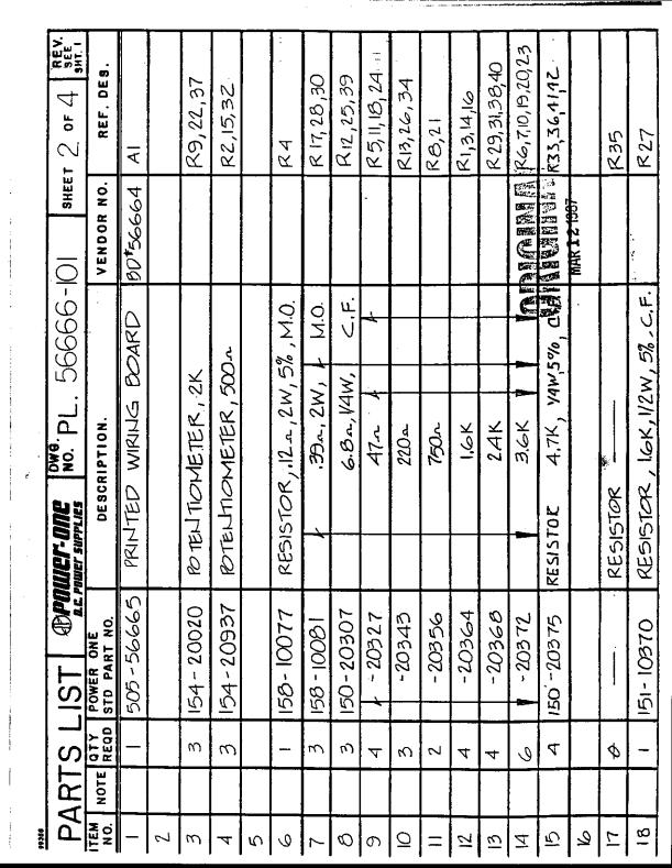
50 4.3.3 CONVERTER CONTROLLER The Converter Controller board contains the microcomputer and analog circuitry necessary to control the LCD display, accept data from the front panel keys, control the frequency synthesizer, monitor status signals from the critical converter components, control the muting and alarm relays and provide a remote bus interface (e.g. RS485). The microcomputer is designed with a microprocessor which contains on-chip RAM, a serial port and an I/O port. Program memory is stored in an EPROM. Additional RAM is located on a peripheral IC along with extra I/O ports and a timer. The I/O ports read the rear panel DIP switch for address and baud rate selection (remote bus option only), control the "MEMORY" and "REMOTE" front panel LEDs, control the muting and alarm relays and monitor the analog status alarm circuitry. The on-chip timer is used as a gated oscillator to sound the buzzer. The I/O port on the microprocessor controls the LCD controller chips, stores and recalls data from the EEPROMs (non volatile memory) and sends serial data to the frequency synthesizer via the interface ICs. When the remote bus option is used, the microprocessor on-chip serial I/O port is used with the interface ICs to provide an RS422/485 interface. Front panel keys are monitored by the keyboard encoder. The keys are scanned at a periodic rate and an interrupt is generated whenever a key is pressed. Key debouncing and multiple key lockout are also provided in the chip. The power monitor IC performs three functions. It generates a power-on reset pulse whenever power is turned on. As a power monitor, it continuously monitors the +5V power supply and generates a reset signal if the supply drops below 4.5V. It also contains a watch dog timer which must be periodically reset by the microprocessor. Failure to do so indicates a circuit failure and causes a reset pulse to be generated. The analog section monitors signal levels from the critical converter components and outputs to the microcomputer whenever a fault level has been reached. Fault levels for the power supplies are fixed while others such as the LO level detect are adjusted with trim pots. A separate relay, DC alarm, is controlled from the output of the power supply monitor circuitry. The two front panel alarm LEDs, "RF-LO" and "IF-LO", are controlled from the analog circuitry. 4-16
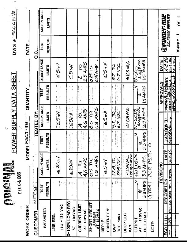
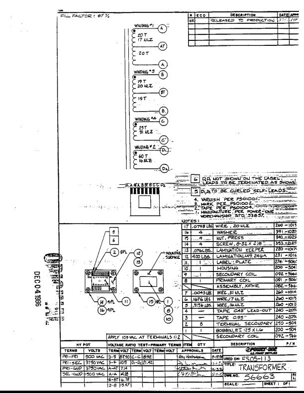
51 4.3.4 POWER SUPPLY, LOW PASS FILTER The complete manual for the power supply is given in Appendix A. MITEQ Part Number: PS120-FS XXXXX Power One Part Number: FS The power supply is divided into three sections: A volts for the Converter Controller only Voltage Setting Tolerance: ±0.10 volts B volts for the converter's RF components Voltage Setting Tolerance: ±0.10 volts C. +20 volts for the converter's RF components Voltage Setting Tolerance: ±0.25 volts Overvoltage protection is included for all sections of the power supply. A low pass filter (A1A4) follows the RF component sections of the power supply to aid in the rejection of power supply noise. A balanced configuration is used with a series inductor and shunt electrolytic capacitor. Voltage is set and monitored after the low pass filter and is supplied to all system components with the exception of the crystal reference oscillator heater circuit. The heater circuit derives DC power before the low pass filter. 4-17
52 SECTION 5 MAINTENANCE 5.1 INTRODUCTION This section includes information and instructions for periodic monitoring of converter performance, and information for troubleshooting, alignment and adjustment of the converter in case of converter malfunction. 5.2 PREVENTIVE MAINTENANCE The converter is a completely solid state design. Normal periodic inspection for cleanliness and mechanical integrity should be made in accordance with standard procedures. To prevent long and costly downtime of the converter periodic monitoring of the overall converter performance parameters that are most indicative of individual converter component performance is necessary. A log should be maintained that provides a permanent record of converter operation and compares it to factory provided data. By doing so, any long term degradation, erratic or abnormal performance can be detected early. The overall converter performance parameters that are most indicative of individual system component performance and encompass all system components for correct overall converter performance are converter gain and local oscillator frequencies. Any excessive change in converter gain indicates a malfunction in the local oscillator and/or signal channel and/or in the power supply. Any excessive frequency change indicates malfunction in phase locking to the reference oscillator DC VOLTAGE Connect the digital voltmeter to the DC test points on the rear panel. If voltage is beyond tolerance (see Section 4.3.4), reset power supply (refer to Appendix and Figure 1-3), using the tuning adjustment on the power supply. 5-1
53
54 5.2.2 GAIN OF THE CONVERTER The following procedure is to be followed for gain measurements. Connect the test equipment as shown in Figure 5-1. Set the sweeper to cover the required input frequency range. Set the attenuator on the log memory scope to 000 and memorize the input reference. Connect the converter into the test setup. Record the gain and frequency response of the converter. The gain of the converter should be periodically monitored to reveal deviations which would indicate possible malfunction FREQUENCY MEASUREMENT Frequency accuracy of the converter is determined by the reference source used. Frequency may be monitored at the rear panel LO test points LOCAL OSCILLATOR PHASE LOCK TEST POINT (Phase Voltage) The phase lock test point (phase voltage) of the phase lock source indicates proper locking conditions and frequency for the basic voltage-tuned oscillator. The following voltages will be observed at 25 C ambient: A. LO1: 10 ±2 volts "in lock" 1 volt or 18 volts "out-of-lock" B. LO2: Variable with frequency Due to the nature of multiple loop frequency synthesizers, the test point may not always indicate an out-of-lock state. The front panel LED represents a summary of the individual phase lock loop alarms. Data on test point voltage should be recorded in a log and compared to the original data in order that changes in data as a function of time can be observed. 5-3
55 5.3 CORRECTIVE MAINTENANCE If the converter malfunctions during normal use or if the tests in Section 5.2 reveal excessive discrepancies in converter gain or local oscillator frequency or test point voltage, isolation and correction of the malfunction becomes necessary. While it is difficult to fully anticipate and describe all possible failure modes in a complicated electronic system, this manual contains sufficient information in the form of theory of operation and diagrams to enable an experienced technician to isolate and remove the malfunctioning module. In addition, power supply failures can be corrected on the station level POWER SUPPLY MALFUNCTION If the fault is detected in the power supply, remove the power supply protective cover. Check AC voltage input to the power supply. With the help of the power supply schematics in Appendix A, isolate the malfunctioning component LOCAL OSCILLATOR To isolate the malfunctioning component in the local oscillator chain, Section should first be carefully studied for theory of operation. The following voltage check should be performed before proceeding. Check DC voltages to phase lock oscillators. A scope (AC coupled) should be applied to voltage line to measure power supply ripple (refer to Appendix for specifications). If incorrect voltage or excessive ripple is observed, refer to Paragraph for a power supply check. Power level of the input reference should be checked. Required input reference power level for phase lock sources is 0±3 dbm. If the reference source is significantly off frequency, the phase lock source may not be able to lock to it. Frequency of the reference should be MHz. Assuming an "in-lock" condition at the correct output frequency, check output power. If unit is out of specification or above procedures fail to rectify the problem, it is recommended that unit be returned for factory repair CONVERTER, SIGNAL CHAIN The components in the signal chain can be checked against the individual specifications listed in Section
56
57
58
59
60
61
62
63
64
65
66
67
68
69
70
71
72
73
74
75
76
77
78
79
80
81
82
83
84
85
86
87
88
89
90
91
92
Back to. Communication Products Group. Technical Notes. Local/Remote Control, 9300 Series
 Back to Communication Products Group Technical Notes 25T001 Local/Remote Control, 9300 Series MITEQ TECHNICAL NOTE 25T001 MAY 1995 REV G 1.0 LOCAL/REMOTE SELECTION LOCAL/REMOTE CONTROL 9300 SERIES CONVERTER
LOCAL/REMOTE CONTROL and FUNCTIONAL DESCRIPTION. UNIVERSAL Ku-BAND TEST TRANSLATOR UNIVERSAL DBS BAND TEST TRANSLATOR
 MITEQ TECHNICAL NOTE 25T022 MARCH 2000 REV H LOCAL/REMOTE CONTROL and FUNCTIONAL DESCRIPTION UNIVERSAL Ku-BAND TEST TRANSLATOR UNIVERSAL DBS BAND TEST TRANSLATOR GENERAL DESCRIPTION The Universal Band
1:1 AND 1:2 REDUNDANT LOW-NOISE AMPLIFIER SYSTEMS
 FEATURES Low amplifier noise temperature Fully redundant power supplies Remote control via RS485 matic/manual control from both local and remote mode Remote status Off-line input/output access Amplifier
OPERATING MANUAL DIGITALLY CONTROLLED FREQUENCY SYNTHESIZED OSCILLATOR MODEL NUMBER: ADSDFS-A DOCUMENT NUMBER: 51A19937C
 OPERATING MANUAL DIGITALLY CONTROLLED FREQUENCY SYNTHESIZED OSCILLATOR MODEL NUMBER: DOCUMENT NUMBER: 51A19937C For More Information, Contact: sales@goochandhousego.com www.goochandhousego.com As part
Technical Description and User Manual E-band CW power meter DPM-12 s/n N-1204/21-T
 ELVA-1 Microwave Ltd. S.A. Mm-wave Division e-mail: sales@elva-1.com Internet: http://www.elva-1.com/ Technical Description and User Manual E-band CW power meter DPM-12 s/n N-1204/21-T 1 Specifications
EXECUTE Shiloh Road Alpharetta, Georgia (770) FAX (770) Toll Free
 FAX (770) Toll Free") Instruction Manual Model 1586-06 RF Attenuator May 2009 Rev A 1 2 3 12.5 53.5 16.3 MODEL 1586 RF ATTENUATOR CROSS TECHNOLOGIES INC. EXECUTE PS1 PS2 Data, drawings, and other material contained herein are
Instruction Manual Model 1586-06 RF Attenuator May 2009 Rev A 1 2 3 12.5 53.5 16.3 MODEL 1586 RF ATTENUATOR CROSS TECHNOLOGIES INC. EXECUTE PS1 PS2 Data, drawings, and other material contained herein are
Block Upconverters for Integration in High Power Amplifiers
 R Back to Block/Fixed Tuned Converters Block Upconverters for Integration in High Power Amplifiers Block Upconverters For Integration In High Power Amplifiers C-, X- and Ku-Band Models (except UPBA-13)
Harris IRT Enterprises Multi-Channel Digital Resistance Tester Model XR
 Harris IRT Enterprises Multi-Channel Digital Resistance Tester Model 6012-06XR Specifications & Dimensions 2 Theory of Operation 3 System Block Diagram 4 Operator Controls & Connectors 5 Test Connections
X-Band Redundant LNA Systems
 X-Band Redundant LNA Systems LRX-1000 Series Introduction Redundant LNA systems minimize system downtime due to LNA failure by providing a spare LNA and an automatic means of switching to the spare upon
C-Band Redundant LNA Systems
 C-Band Redundant LNA Systems LRC-1000 Series Introduction Redundant LNA systems minimize system downtime due to LNA failure by providing a spare LNA and an automatic means of switching to the spare upon
411LA Broadband Power Amplifier
 411LA Broadband Power Amplifier HIGH RF VOLTAGES MAY BE PRESENT AT THE OUTPUT OF THIS UNIT. All operating personnel should use extreme caution in handling these voltages and be thoroughly familiar with
2100L Broadband Power Amplifier
 2100L Broadband Power Amplifier HIGH RF VOLTAGES MAY BE PRESENT AT THE OUTPUT OF THIS UNIT. All operating personnel should use extreme caution in handling these voltages and be thoroughly familiar with
Appendix A. Datum Systems PSM-2100/512 Satellite Modem. Technical Specification
 Appendix A Datum Systems PSM-2100/512 Satellite Modem Technical Specification PSM-2100 and PSM-512 VSAT / SCPC - Modem Specification Revision History Rev 1.0 6-15-97 Preliminary Release. Rev 1.1 10-10-97
A NEW GENERATION PROGRAMMABLE PHASE/AMPLITUDE MEASUREMENT RECEIVER
 GENERAL A NEW GENERATION PROGRAMMABLE PHASE/AMPLITUDE MEASUREMENT RECEIVER by Charles H. Currie Scientific-Atlanta, Inc. 3845 Pleasantdale Road Atlanta, Georgia 30340 A new generation programmable, phase-amplitude
Instruction Manual Model Block Translator
 Instruction Manual Model 2083-21-1422 Block Translator October 2018, Rev. 0 1385>2230 G=20 TRX=846.001010 MHz MENU MODEL 2083 TRANSLATOR CROSS TECHNOLOGIES INC. REMOTE POWER ALARM EXECUTE Data, drawings,
Agilent 8360B Series Synthesized Swept Signal Generators 8360L Series Synthesized Swept CW Generators Data Sheet
 Agilent 8360B Series Synthesized Swept Signal Generators 8360L Series Synthesized Swept CW Generators Data Sheet 10 MHz to 110 GHz Specifications apply after full user calibration, and in coupled attenuator
PI-10 Broadband Power Indicator
 PI-10 Broadband Power Indicator HIGH RF VOLTAGES MAY BE PRESENT AT THE PORTS OF THIS UNIT. All operating personnel should use extreme caution in handling these voltages and be thoroughly familiar with
Maintenance Manual. MTD SERIES 900 MHz, 10-WATT, DATA ONLY MOBILE RADIO. Mobile Communications LBI TABLE OF CONTENTS
 Mobile Communications MTD SERIES 900 MHz, 10-WATT, DATA ONLY MOBILE RADIO TABLE OF CONTENTS RF BOARD............................... LBI-38545 AUDIO BOARD............................ LBI-38546 LOGIC BOARD............................
3100LA Broadband Power Amplifier
 3100LA Broadband Power Amplifier HIGH RF VOLTAGES MAY BE PRESENT AT THE OUTPUT OF THIS UNIT. All operating personnel should use extreme caution in handling these voltages and be thoroughly familiar with
EDACS WALL MOUNT STATION. Maintenance Manual. Mobile Communications LBI-31838A TABLE OF CONTENTS
 A Mobile Communications EDACS WALL MOUNT STATION TABLE OF CONTENTS SYSTEM BOARD & REGULATOR BOARD.......... LBI-31892 KEY/DISPLAY BOARD MAINTENANCE MANUAL.... LBI-31940 Maintenance Manual Printed in U.S.A.
ericssonz LBI-38640E MAINTENANCE MANUAL FOR VHF TRANSMITTER SYNTHESIZER MODULE 19D902780G1 DESCRIPTION
 MAINTENANCE MANUAL FOR VHF TRANSMITTER SYNTHESIZER MODULE 19D902780G1 TABLE OF CONTENTS Page DESCRIPTION........................................... Front Cover GENERAL SPECIFICATIONS...................................
A 500 Broadband Power Amplifier
 A 500 Broadband Power Amplifier HIGH RF VOLTAGES MAY BE PRESENT AT THE OUTPUT OF THIS UNIT. All operating personnel should use extreme caution in handling these voltages and be thoroughly familiar with
PI-150 Broadband Power Indicator
 PI-150 Broadband Power Indicator HIGH RF VOLTAGES MAY BE PRESENT AT THE PORTS OF THIS UNIT. All operating personnel should use extreme caution in handling these voltages and be thoroughly familiar with
Agilent Technologies PSA Series Spectrum Analyzers Test and Adjustment Software
 Test System Overview Agilent Technologies PSA Series Spectrum Analyzers Test and Adjustment Software Test System Overview The Agilent Technologies test system is designed to verify the performance of the
The MP SERIES CONTROLLER. User s Manual. ISE, Inc.
 The MP SERIES CONTROLLER User s Manual ISE, Inc. 10100 Royalton Rd. Cleveland, OH 44133 USA Tel: (440) 237-3200 Fax: (440) 237-1744 http://variac.com Form No, 003-1622 Rev G 02/25/2009 Form No. 003-1622
2.9GHz SPECTRUM ANALYZER
 2.9GHz SPECTRUM ANALYZER Introducing a new 2.9GHz Spectrum Analyzer Manufacturing Research and Development Field Service Education Powerful capacity by advanced digital synthesizer Revolutionary features
Digital HF Receiver WJ-8723
 Developmental Specification WATKINS-JOHNSON April 1996 Digital HF Receiver WJ-8723 Description The WJ-8723 is a fully synthesized, general-purpose HF receiver that monitors RF communications from 5 khz
EO Modulator Driver and Source Models 3363-A, 3363-B, and 3363-C
 USER S GUIDE EO Modulator Driver and Source Models 3363-A, 3363-B, and 3363-C 2584 Junction Ave. San Jose, CA 95134-1902 USA phone: (408) 919-1500 e-mail: contact@newfocus.com www.newfocus.com Warranty
SOUTHERN AVIONICS COMPANY. SE125 Transmitter. SE125 Transmitter 1-1
 1-1 1 Introduction The SE Series transmitters are computer controlled systems designed around an embedded microprocessor. These systems are capable of remote monitoring and maintenance via Ethernet (optional).
FREQUENCY AGILE FM MODULATOR INSTRUCTION BOOK IB
 FMT615C FREQUENCY AGILE FM MODULATOR INSTRUCTION BOOK IB1215-02 TABLE OF CONTENTS SECTION SUBJECT 1.0 Introduction 2.0 Installation & Operating Instructions 3.0 Specification 4.0 Functional Description
Broadband Power Amplifier
 601L Broadband Power Amplifier HIGH RF VOLTAGES MAY BE PRESENT AT THE OUTPUT OF THIS UNIT. All operating personnel should use extreme caution in handling these voltages and be thoroughly familiar with
Solid State General Communication Power Amplifier
 The GCS1D2GUT (SKU 4062) is suitable for broadband high power linear applications in the HF frequency range. This rack mount amplifier utilizes pushpull MOSFET power devices that provide high gain, wide
Mastr III P25 Base Station Transmitter Tune-up Procedure
 Mastr III P25 Base Station Transmitter Tune-up Procedure 1. Overview The Mastr III Base Station transmitter alignment is performed in several steps. First, the Transmit Synthesizer module is aligned to
Single Channel Loop Detector
 Single Channel Loop Detector Model LD120T Series The LD120T is a series of single channel inductive loop detectors. The use of microprocessor and surface mount technology enables a large number of functions
COM-POWER OPERATION MANUAL ACS W
 COM-POWER OPERATION MANUAL For the ACS-250-100W 150 khz to 250 MHz 100W Power Amplifier Page 1 of 15 MANUAL_ACS-250-100W Rev. M02.15 Table of Contents Important Safety Precautions.....3 Introduction..5
Phase Matrix, Inc. 545B 548B. Phase Matrix, Inc. EIP 545B and 548B CW Frequency Counters. Instruments You Can Count On
 Phase Matrix, Inc. Instruments You Can Count On 545B 548B Phase Matrix, Inc. EIP 545B and 548B CW Frequency Counters Full Function CW Microwave Frequency Counters with Selective Power Measurement Keyboard
PLUG N PLAY WATT DIGITAL FM TRANSMITTER. April, 2002 IM No
 PLUG N PLAY 1000 1000 WATT DIGITAL FM TRANSMITTER April, 2002 IM No. 597 9972 OPERATION/FEATURE PROGRAMMING. The PNP 1000 allows the user to select many types of different operating parameters and features.
Indoor Rack Mount. GaN Solid State Power Amplifiers 3RU Rack Height
 300W S-Band 3RU SSPA Chassis with 1RU N+1 Power Supply Teledyne Paradise Datacom has a rich history in the design and production of Gallium Nitride (GaN) based SSPAs. Our engineers utilize innovative linearization
GPS Time and Frequency Reference Receiver
 $ GPS Time and Frequency Reference Receiver Symmetricom s 58540A GPS time and frequency reference receiver features: Eight-channel, parallel tracking GPS engine C/A Code, L1 Carrier GPS T-RAIM satellite
INSTALLATION and OPERATION INSTRUCTIONS. FOR FiberLink BI-DIRECTIONAL AMPLIFIER WITH DIVERSITY MW-FBDA-800AB-50W-DIV
 INSTALLATION and OPERATION INSTRUCTIONS FOR FiberLink BI-DIRECTIONAL AMPLIFIER WITH DIVERSITY MW-FBDA-800AB-50W-DIV Page 1 of 15 TABLE OF CONTENTS PARA No. PARAGRAPH PAGE No. 1. OVERVIEW 3 2. COMPONENT
FEATURES: Reduced Depth. Output RF Power Hold. Easily Accessible Diagnostic Port. Programmable Alarms. Event And Maintenance Logs. Ethernet Interface
 MT3200A TRAVELING WAVE TUBE MEDIUM POWER AMPLIFIER FOR SATELLITE UPLINK APPLICATIONS C-BAND: 400W X-BAND: 400W Ku-BAND: 400W DBS-BAND: 270W DUAL C-/Ku-BAND: 325W DUAL Ku-/DBS-BAND: 350W AVAILABLE SYSTEM
TECHNICAL MANUAL TM0110-2
 TECHNICAL MANUAL TM0110-2 RUBIDIUM FREQUENCY STANDARD MODEL FE-5680A SERIES OPTION 2 OPERATION AND MAINTENANCE INSTRUCTIONS Rubidium Frequency Standard Model FE-5680A with Option 2 Frequency Electronics,
1 FUNCTIONAL DESCRIPTION WAY SPLITTER/INPUT BOARD FET RF AMPLIFIERS WAY POWER COMBINER VSWR CONTROL BOARD...
 CONTENTS 1 FUNCTIONAL DESCRIPTION...1 2 4-WAY SPLITTER/INPUT BOARD...2 3 FET RF AMPLIFIERS...3 4 4-WAY POWER COMBINER...4 5 VSWR CONTROL BOARD...5 6 ADJUSTMENT OF BIAS VOLTAGE TO ESTABLISH PROPER QUIESCENT
1140LA Broadband Power Amplifier
 1140LA Broadband Power Amplifier HIGH RF VOLTAGES MAY BE PRESENT AT THE OUTPUT OF THIS UNIT. All operating personnel should use extreme caution in handling these voltages and be thoroughly familiar with
Henry Dudley 1508 Wellington Ave. Toms River, NJ
 Henry Dudley 1508 Wellington Ave. Toms River, NJ 08757 732-240-6895 hdudley@dudleylab.com OM000001 REV01 RELEASE DATE 1/27/04 TABLE OF CONTENTS TABLE OF CONTENTS... 2 1.0 GENERAL INFORMATION... 3 1.1 Scope
MT3200A TRAVELING WAVE TUBE MEDIUM POWER AMPLIFIER
 ISO 9001 MODEL MT3200A TRAVELING WAVE TUBE MEDIUM POWER AMPLIFIER MT3200A TRAVELING WAVE TUBE MEDIUM POWER AMPLIFIER FOR SATELLITE FOR SATELLITE UPLINK UPLINK APPLICATIONS C-BAND: 400W X-BAND: 400W Ku-BAND:
Technical Equipment Specification
 STATE OF CALIFORNIA Office of the State Chief Information Officer Public Safety Communications Division Technical Equipment Specification Equipment Type: Transmitter/Receiver Mobile Relay/Base/Control
INSTALLATION & OPERATING INSTRUCTIONS
 INSTALLATION & OPERATING INSTRUCTIONS IM-276 Model 3200T, 3201T, 3250T Series SmartStep Programmable Attenuators This documentation may not be reproduced in any form, for any purpose unless authorized
MAINTENANCE MANUAL RF BOARD 19D901835G1 ( MHz) 19D901835G2 ( MHz) FOR MVS
 19D901835G2 ( MHz) FOR MVS") D MAINTENANCE MANUAL F BOAD 19D901835G1 (136-153 MHz) 19D901835G2 (150-174 MHz) FO MVS TABLE OF CONTENTS DESCIPTION............................................... Front Cover CICUIT ANALYSIS..............................................
D MAINTENANCE MANUAL F BOAD 19D901835G1 (136-153 MHz) 19D901835G2 (150-174 MHz) FO MVS TABLE OF CONTENTS DESCIPTION............................................... Front Cover CICUIT ANALYSIS..............................................
khz to 2.9 GHz Spectrum Analyzer
 Spectrum Analyzers 2399 9 khz to 2.9 GHz Spectrum Analyzer A spectrum analyzer with outstanding performance and a user friendly visual interface simplifying many complex measurements. 9 khz to 2.9 GHz
INSTRUMENTS, INC. INSTRUCTION MANUAL Precision 350 MHz Synthesizer. Model 425A. Table of Contents. Section Page Contents
 INSTRUMENTS, INC. INSTRUCTION MANUAL Precision 350 MHz Synthesizer Model 425A Table of Contents Section Page Contents 1.0............................. 2......................... Description 2.0.............................
Applications. Operating Modes. Description. Part Number Description Package. Many to one. One to one Broadcast One to many
 RXQ2 - XXX GFSK MULTICHANNEL RADIO TRANSCEIVER Intelligent modem Transceiver Data Rates to 100 kbps Selectable Narrowband Channels Crystal controlled design Supply Voltage 3.3V Serial Data Interface with
Frequency Synthesizer Project ECE145B Winter 2011
 Frequency Synthesizer Project ECE145B Winter 2011 The goal of this last project is to develop a frequency synthesized local oscillator using your VCO from Lab 2. The VCO will be locked to a stable crystal
SynthNV - Signal Generator / Power Detector Combo
 SynthNV - Signal Generator / Power Detector Combo The Windfreak SynthNV is a 34.4MHz to 4.4GHz software tunable RF signal generator controlled and powered by a PC running Windows XP, Windows 7, or Android
MASTR II AUXILIARY RECEIVER 19D417546G7 & G8 & ANTENNA MATCHING UNITS 19C321150G1-G2. Maintenance Manual LBI-30766L. Mobile Communications
 L Mobile Communications MASTR II AUXILIARY RECEIVER 19D417546G7 & G8 & ANTENNA MATCHING UNITS 19C321150G1-G2 Printed in U.S.A Maintenance Manual TABLE OF CONTENTS Page SPECIFICATIONS.....................................................
INC. MICROWAVE. A Spectrum Control Business
 DRO Selection Guide DIELECTRIC RESONATOR OSCILLATORS Model Number Frequency Free Running, Mechanically Tuned Mechanical Tuning BW (MHz) +10 MDR2100 2.5-6.0 +10 6.0-21.0 +20 Free Running, Mechanically Tuned,
Agilent 8360B/8360L Series Synthesized Swept Signal/CW Generators 10 MHz to 110 GHz
 Agilent 8360B/8360L Series Synthesized Swept Signal/CW Generators 10 MHz to 110 GHz ity. l i t a ers V. n isio c e r P. y t i l i ib Flex 2 Agilent 8360 Synthesized Swept Signal and CW Generator Family
HR1200. Version 1.00 ATIM RADIOCOMMUNICATION 1/11
 HR1200 Version 1.00 ATIM RADIOCOMMUNICATION 1/11 Contact Information ATIM RADIOCOMMUNICATION Les guillets 38250 Villard de Lans France Tel : +33 (0)4 76 95 50 65 Fax: +33 (0)4 76 95 50 64 Web : www.atim.com
INSTRUCTION MANUAL MODEL 2779 SUBCARRIER MODULATOR
 INSTRUCTION MANUAL MODEL 2779 SUBCARRIER MODULATOR Data, drawings, and other material contained herein are proprietary to Cross Technologies, Inc., and may not be reproduced or duplicated in any form without
Ocean Controls KT-5221 Modbus IO Module
 Ocean Controls Modbus IO Module 8 Relay Outputs 4 Opto-Isolated Inputs 2 Analog Inputs (10 bit) 1 PWM Output (10 bit) 4 Input Counters Connections via Pluggable Screw Terminals 0-5V or 0-20mA Analog Inputs,
Ku-Band VSAT Block Up Converters
 FEATURES Single box BUC output power levels to 10W RS485 M&C capability Accurate RF Power Monitoring Maintenance Free Operation +24VDC or +48 VDC input voltage OPTIONS 10W L-Band to Ku-Band Block Up Converter
DANFYSIK A/S - DK-4040 JYLLINGE - DENMARK
 2 TABLE OF CONTENTS PAGE 1. INTRODUCTION AND SPECIFICATIONS. 1.1 Introduction... 4 1.1.1 Working principle....4 1.2 Warranty...5 2. RECEIVING AND UNPACKING. 2.1 Receiving the goods....6 2.2 Instructions
Frequency Stability dbc/hz/hour / Sweeping locking Time ms
 Summary CW and Analog High Power (+24dBm) Signal Generator 2-13GHz General Specification Frequency range 2 13GHz Output power: +24dBm max. Reverse power protection. Dynamitic power range: 28dB Sweeping
SMARTALPHA RF TRANSCEIVER
 SMARTALPHA RF TRANSCEIVER Intelligent RF Modem Module RF Data Rates to 19200bps Up to 300 metres Range Programmable to 433, 868, or 915MHz Selectable Narrowband RF Channels Crystal Controlled RF Design
Installation and Operation Manual
 Installation and Operation Manual PTG-10 Pilot Tone Generator Designed and Manufactured by: JPS Interoperability Solutions 5800 Departure Drive Raleigh, NC 27616 919-790-1011 Email: sales@jpsinterop.com
Line-to-line RMS Volts, 3 phases 4 digits (XXX.X) Volts
 Volts") digital ac POWER MONITOR DESCRIPTION The DSP is a three-phase, three-element multifunction digital transducer with outputs for voltage, current, and power via serial communication. Applications include
digital ac POWER MONITOR DESCRIPTION The DSP is a three-phase, three-element multifunction digital transducer with outputs for voltage, current, and power via serial communication. Applications include
TECHNICAL MANUAL OPERATOR'S, ORGANIZATIONAL, DIRECT SUPPORT, AND GENERAL SUPPORT MAINTENANCE MANUAL (INCLUDING REPAIR PARTS AND SPECIAL TOOLS LIST)
") TM 11-6625-2781-14&P-5 TECHNICAL MANUAL OPERATOR'S, ORGANIZATIONAL, DIRECT SUPPORT, AND GENERAL SUPPORT MAINTENANCE MANUAL (INCLUDING REPAIR PARTS AND SPECIAL TOOLS LIST) FOR PLUG-IN, LOW FREQUENCY (SPECTRUM
TM 11-6625-2781-14&P-5 TECHNICAL MANUAL OPERATOR'S, ORGANIZATIONAL, DIRECT SUPPORT, AND GENERAL SUPPORT MAINTENANCE MANUAL (INCLUDING REPAIR PARTS AND SPECIAL TOOLS LIST) FOR PLUG-IN, LOW FREQUENCY (SPECTRUM
Instruction Manual Model
 Instruction Manual Model 2099-24 10MHz Source/Inserter, Redundant Power August 2016, Rev. 0 MODEL 2099 SOURCE / INSERTER ALARM DC ON REF ON LNB1 LNB2 MENU EXECUTE LNB1 +24.2V @ 0.249A LNB2 +23.8V @ 0.251A
Specification RIGOL. 6 Specification
 Specification RIGOL 6 Specification This chapter lists the specifications and general specifications of the analyzer. All the specifications are guaranteed when the following conditions are met unless
EC Declaration of Conformity
 EC Declaration of Conformity We; Amplifier Research 160 School House Road Souderton, Pa. 18964 declare that as of 1997, our product(s); the Model 100A250 series amplifiers to which this declaration relates
GT 9000 GT 9000S MICROWAVE
 Page 1 of 6 GT 9000 GT 9000S MICROWAVE Now you can get the performance you need and the capability you want, at a price you can afford. Both the Giga-tronics GT9000 Microwave Synthe- techniques.together,
Multi-Function Assemblies
 K&L Microwave offers a variety of (MFA) products to satisfy a broad range of filtering applications. Many applications require frequency pre-selection at the front end of the communication or test and
2026Q CDMA/GSM Interferer MultiSource Generator
 Signal Sources 2026Q CDMA/GSM Interferer MultiSource Generator The 2026Q is designed to work with a radio test set to provide a fully integrated radio receiver test solution for cellular and PCS systems
FREQUENCY SYNTHESIZERS, SIGNAL GENERATORS
 SYNTHESIZED SWEEP/SIGNAL GENERATOR 69A, 68B series 10 MHz to 6 GHz GPIB A microwave synthesizer for any application Anritsu Wiltron s El Toro microwave synthesizers present 80 models, providing you the
GT-1050A 2 GHz to 50 GHz Microwave Power Amplifier
 Established 1981 Advanced Test Equipment Rentals www.atecorp.com 800-404-ATEC (2832) Giga-tronics GT-1050A Microwave Power Amplifier GT-1050A 2 GHz to 50 GHz Microwave Power Amplifier Operation Manual
E3 Adjustable Speed Drive Engineering Specification
 E3 Adjustable Speed Drive Engineering Specification PART 1 - GENERAL 1.0 Scope This specification shall cover Toshiba E3 AC Variable Frequency Drives, 6 pulse for 230V and 460V. 1.1 References A. National
MODEL AF200A: FM, FM/SCA RECEIVER/MONITOR OPERATION MANUAL
 MODEL AF200A: FM, FM/SCA RECEIVER/MONITOR OPERATION MANUAL THE AF200A IS AN FM AND FM/SCA PROFESSIONAL STYLE RECEIVER/ MONITOR. IT S MANY APPLICATIONS INCLUDE STATION MONITORING AND EAS MONITORING. The
Agilent 8902A Measuring Receiver
 Agilent 8902A Measuring Receiver Technical Specifications Agilent 11722A Sensor Module Agilent 11792A Sensor Module Agilent 11793A Microwave Converter Agilent 11812A Verification Kit The Agilent Technologies
PA FAN PLATE ASSEMBLY 188D6127G1 SYMBOL PART NO. DESCRIPTION. 4 SBS /10 Spring nut. 5 19A702339P510 Screw, thread forming, flat head.
 MAINTENANCE MANUAL 851-870 MHz, 110 WATT POWER AMPLIFIER 19D902797G5 TABLE OF CONTENTS Page DESCRIPTION.............................................. Front Page SPECIFICATIONS.................................................
INSTRUCTION MANUAL MODEL 2455T SUBCARRIER MODULATOR
 INSTRUCTION MANUAL MODEL 2455T SUBCARRIER MODULATOR Data, drawings, and other material contained herein are proprietary to Cross Technologies, Inc., and may not be reproduced or duplicated in any form
The Allen-Bradley Servo Interface Module (Cat. No SF1) when used with the Micro Controller (Cat. No UC1) can control single axis
 when used with the Micro Controller (Cat. No UC1) can control single axis") Table of Contents The Allen-Bradley Servo Interface Module (Cat. No. 1771-SF1) when used with the Micro Controller (Cat. No. 1771-UC1) can control single axis positioning systems such as found in machine
Table of Contents The Allen-Bradley Servo Interface Module (Cat. No. 1771-SF1) when used with the Micro Controller (Cat. No. 1771-UC1) can control single axis positioning systems such as found in machine
MODEL 4212C INSTRUCTION MANUAL. Table of contents 1.1 FEATURES 1.4 WARRANTY
 MODEL 4212C INSTRUCTION MANUAL Table of contents Page 1 1 2 3 6 6 6 1. GENERAL INFORMATION 1.1 FEATURES 1.2 INSTRUMENT IDENTIFICATION & OPTIONS 1.3 TECHNICAL SPECIFICATIONS 1.4 WARRANTY 1.5 UNPACKING AND
Model 34A. 3Hz to 2MHz 2-Channel Butterworth/Bessel HP, LP, BP, BR Plug-In Filter Card for Model 3905/3916 Chassis.
 Model 34A 3Hz to 2MHz 2-Channel Butterworth/Bessel HP, LP, BP, BR Plug-In Filter Card for Model 3905/3916 Chassis Operating Manual Service and Warranty Krohn-Hite Instruments are designed and manufactured
Multi-Channel RS-232 Serial RF Transceiver
 RF-232 Multi-Channel RS-232 Serial RF Transceiver The RF-232 subassembly is a multi-channel serial radio transceiver. This device accepts and outputs standard serial data at one of three selectable data
C-Band VSAT Block Up Converters
 FEATURES Single box BUC output power levels to 20W RS485 M&C capability Accurate RF Power Monitoring Maintenance Free Operation +24VDC or +48 VDC input voltage OPTIONS Antenna Mounting Kit Form A Summary
Product Specification for model TT Transducer Tester Rev. B
 TT Rev B April 20, 2010 Product Specification for model TT Transducer Tester Rev. B The Rapid Controls model TT Rev B transducer tester connects to multiple types of transducers and displays position and
OPERATING MANUAL VOLTAGE CONTROLLED OSCILLATOR MODEL NUMBER: 21XXX-YYY-ZAMVCO DOCUMENT NUMBER: 51A18412A
 OPERATING MANUAL VOLTAGE CONTROLLED OSCILLATOR MODEL NUMBER: 21XXX-YYY-ZAMVCO DOCUMENT NUMBER: 51A18412A This Operating Manual is for use with Variable Frequency AOM Drivers with model numbers: XXX = The
4RU Rack Mountable. Solid State Power Amplifiers
 FEATURES 600W C-Band SSPA Chassis Teledyne Paradise Datacom s Indoor, Rack Mount (R) series SSPAs represent the latest in High Power Microwave Amplifier Technology. The 4RU SSPA chassis achieves the highest
Installation & Service Manual
 869-894 MHz Installation & Service Manual Model SCA 9321-30C Single-Channel Cellular Amplifier 044-xxxxx Rev.A February 2003 2003 Powerwave Technologies Incorporated. All rights reserved. Powerwave Technologies,
Select datum Page backward in. parameter list
 HEIDENHAIN Working with the measured value display unit ND Actual value and input display (7-segment LED, 9 decades and sign) Select datum Page backward in parameter list Confirm entry value Set display
Solid State Broadband High Power Amplifier
 The BBS4A5AVT (2157) is suitable L & S Bands broadband or band specific high power applications. This amplifier utilizes high power GaN devices that provide wide frequency response, high gain, high peak
CAT-700B Repeater Controller Computer Automation Technology, Inc
 CAT-00B Repeater Controller Computer Automation Technology, Inc N.W. st Avenue, Suite Fort Lauderdale, Florida 0 Phone: () 8- Fax: () 88-8 Internet: http://www.catauto.com Table of Contents Chapter Page.
INTRODUCTION STANDARD FEATURES. Option: High ambient temperature operation (up to 60 C) APPLICATION KU-BAND BOOSTER AMPLIFIER
 APPLICATION KU-BAND BOOSTER AMPLIFIER") KU-BAND BOOSTER AMPLIFIER Output Power 16 W to 50 W AWSB-K16; AWSB-K20; AWSB-K25; AWSB-K32; AWSB-K40; AWSB-K50 INTRODUCTION The AWSB-K series described in this section are Advantech s line of medium gain
KU-BAND BOOSTER AMPLIFIER Output Power 16 W to 50 W AWSB-K16; AWSB-K20; AWSB-K25; AWSB-K32; AWSB-K40; AWSB-K50 INTRODUCTION The AWSB-K series described in this section are Advantech s line of medium gain
OVEN INDUSTRIES, INC. Model 5C7-362
 OVEN INDUSTRIES, INC. OPERATING MANUAL Model 5C7-362 THERMOELECTRIC MODULE TEMPERATURE CONTROLLER TABLE OF CONTENTS Features... 1 Description... 2 Block Diagram... 3 RS232 Communications Connections...
FMR622S DUAL NARROW BAND SLIDING DE-EMPHASIS DEMODULATOR INSTRUCTION BOOK IB
 FMR622S DUAL NARROW BAND SLIDING DE-EMPHASIS DEMODULATOR INSTRUCTION BOOK IB 1222-22 TABLE OF CONTENTS SECTION 1.0 INTRODUCTION 2.0 INSTALLATION & OPERATING INSTRUCTIONS 3.0 SPECIFICATIONS 4.0 FUNCTIONAL
Technical Data. Digital HF Receiver WJ-8712A WATKINS-JOHNSON. Features
 May 1996 Technical Data WATKINS-JOHNSON Digital HF Receiver WJ-8712A The WJ-8712A is a fully synthesized, general-purpose HF receiver for surveillance and monitoring of RF communications from 5 khz to
INSTRUMENTS, INC. Models 2960AR and 2965AR Disciplined Rubidium Frequency Standards. Section Page Contents
 INSTRUMENTS, INC. Models 2960AR and 2965AR Disciplined Rubidium Frequency Standards 2960AR 2965AR Section Page Contents 1.0............................. 2......................... Description 2.0.............................
DEM Part Number L144-28INTCK 144 MHz Transverter Kit and complete kit
 DEM Part Number L144-28INTCK 144 MHz Transverter Kit and complete kit Power Out: Noise Figure and Gain: DC Power Requirement: 50 mw linear minimum 3.5 db NF nominal, 5 dbg maximum 12-15.5 VDC, 13.8 nominal
LBI-31564A. Mobile Communications. DELTA - SX MHz RADIO COMBINATIONS (NEGATIVE GROUND ONLY) Maintenance Manual
 Maintenance Manual") A Mobile Communications DELTA - SX 136-174 MHz RADIO COMBINATIONS (NEGATIVE GROUND ONLY) Maintenance Manual TABLE OF CONTENTS MILITARY AND SYSTEM SPECIFICATIONS................................. 2-3 COMBINATION
A Mobile Communications DELTA - SX 136-174 MHz RADIO COMBINATIONS (NEGATIVE GROUND ONLY) Maintenance Manual TABLE OF CONTENTS MILITARY AND SYSTEM SPECIFICATIONS................................. 2-3 COMBINATION
This section lists the specications for the Agilent 8360 B-Series. generators, Agilent Technologies has made changes to this product
 2c Specifications This section lists the specications for the Agilent 8360 B-Series swept signal generator. In a eort to improve these swept signal generators, Agilent Technologies has made changes to