A NEW GENERATION PROGRAMMABLE PHASE/AMPLITUDE MEASUREMENT RECEIVER
|
|
|
- Britton Gilmore
- 6 years ago
- Views:
Transcription
1 GENERAL A NEW GENERATION PROGRAMMABLE PHASE/AMPLITUDE MEASUREMENT RECEIVER by Charles H. Currie Scientific-Atlanta, Inc Pleasantdale Road Atlanta, Georgia A new generation programmable, phase-amplitude measurement receiver has been developed which advances the state-of-the-art of antenna pattern measurements. The new receiver features microprocessor-based control and data processing systems resulting in improved performance and versatility. THE BASIC PHASE-LOCKED RF/IF CONVERSION SYSTEM A block diagram of the phase-locked RF/IF conversion system used in Scientific-Atlanta phase/amplitude measurement receivers is shown by Figure 1. The system permits phase-locking of the receiver to a sample of a received signal supplied to the RF input of the APC CH mixer. When phase-locked, RF signals supplied to the inputs of the APC CH mixer and the SIG CH mixer are converted to coherent low-frequency IF outputs. The IF phase-lock loop causes two crystal-stabilized oscillators (frequencies = MHz and MHz) to be sampled, mixed and then phase-locked to maintain a constant difference frequency (5020 Hz in Figure 1). This difference frequency is determined by the 5020 Hz phase-lock reference supplied to the IF phase detector. An output of the MHz oscillator is supplied as the phase-lock reference to the RF phase-lock system. Buffered outputs of the MHz oscillator are coupled as local oscillator inputs to the automatic phase control channel (APC CH) and the signal channel (SIG CH) second mixers. When the voltage-tuned local oscillator output is phase-locked to the received signal frequency, the signals supplied to the APC CH mixer and SIG CH mixer are each converted to MHz intermediate frequencies. Since the MHz oscillator output serves as the reference for the RF phase-lock loop, the MHz SIG CH and APC CH IF signals are coherent with both the MHz and MHz signals generated in the IF phase lock loop. This relationship results in the MHz APC CH and SIG CH signals supplied to the associated second mixers being converted to coherent 5020 Hz signals. DESIRABLE RECEIVER CHARACTERISTICS A receiver designed to perform as a general purpose phase/amplitude measurement receiver having features required for general antenna pattern range data measurement should have the following: wide frequency range good sensitivity adequate dynamic range capability of mixer remoting and separation two-channel or three-channel capability automatic control capability high data-rate capability frequency agility digital/analog data output capability accurate phase/amplitude data readout good long term stability high interchannel isolation
2
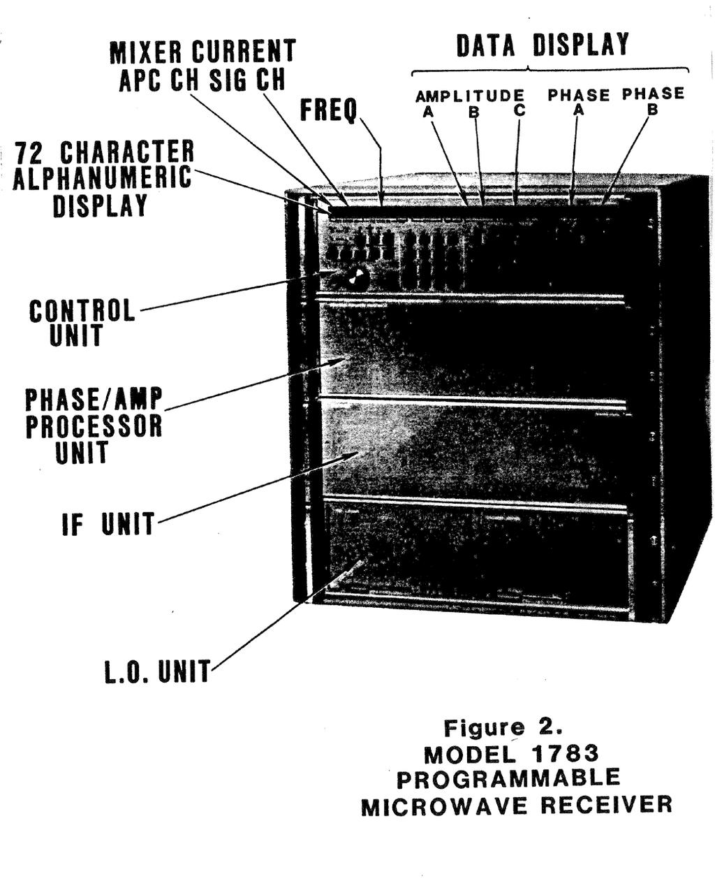
3 THE SERIES 1780 PROGRAMMABLE MICROWAVE RECEIVER A photograph of the Series 1780 Programmable Microwave Receiver is shown by Figure 2. The assembly consists of four rack mounting subunits, each of which is 51/4 inches high. All receiver controls and displays are mounted on the front panel of top unit, which is the microprocessor-based control unit. This panel includes a 72 character alphanumeric display, a keypad, control buttons and LED indicators. A block diagram of a Model 1783 three-channel receiver is shown in Figure 3. The IEEE-488 standard-buscompatible control unit interfaces with other receiver units to supply power and control. When the receiver is phase-locked to a signal supplied to the APC CH RF input, the signals supplied to the APC CH and SIG CH RF inputs are converted to coherent 5020-Hz outputs. These 5020-Hz outputs are coupled to the phase-amplitude processor for A/D conversion and processing. An RF switch operating at a 27.5 khz rate and synchronized with an IF switch located in the IF unit directs the CH A and CH B RF inputs to the CH A and CH B IF channels respectively. This arrangement provides three input/output channels using two mixers and offers improved phase measurement stability when phase is measured between SIG CH A and SIG CH B. Since the signal-channel mixers and associated receiver-to-mixer cable are common to channels A and B, phase errors due to mechanical or thermal effects in the mixer or cable will cancel. The microprocessor-based phase/amplitude processor processes the 5020-Hz IF inputs. The processing consists of predetection filtering, post-detection filtering, phase measurements, amplitude function generation (linear, logarithmic or direct ratios), amplitude measurements and output-data formatting. All operations are carried out for three-amplitude channels and two phase channels. The phase/amplitude processor furnishes both a digital (byteserial) output and an analog output for recording. The recorder output can be programmed to record either any single amplitude channel, any single phase channel or to be OFF. A total of thirty-two front-panel-programmable service-mode routines are provided in the receiver to facilitate alignment and maintenance. The service modes permit the receiver keyboard and display to be used in an alternate mode of operation. In this mode normal receiver operations are suspended and stored procedures may be used to (1) enter auxiliary frequency band information, (2) enter preset mixer currents and receiver options, (3) to exercise tests and programs that confirm system operation, and (4) assist in general troubleshooting.
4
5 RECEIVER OPERATING MODES The Series 1780 receivers have four programmable operating modes (see Figures 4 and 5). The RF/IF signal paths for operating in the DUAL 1 mode are shown by Figure 4A. In this configuration, the SIG CH A RF and the APC CH RF are converted to IF in the appropriate channels. The RF/IF signal paths when operating in the DUAL 2 mode are shown by Figure 4B. The signal paths are identical to those of the DUAL 1 mode except the RF switch is switched to select the SIG CH B RF input. The DUAL 1/DUAL 2 modes provide the user with a means of using the external RF switch as a programmable coaxial relay. The SHARED AB mode signal paths are shown by Figure 5B. When operating in this mode, the RF SIG CH A and the RF SIG CH B inputs are synchronously switched at 27.5 khz such that the signal channel passes both the CH A IF and CH B IF signals simultaneously. This configuration has three RF inputs and three RF outputs. The DUAL 1 mode (Figure 4A) and the SHARED B mode (Figure 5C) SIG CH RF/IF paths are identical to the two switched RF/IF signal paths of the SHARED AB mode. Static evaluation of either of the two SHARED AB RF/IF signal paths can be accomplished by operating either in the DUAL 1 or the SHARED B mode. AUTOMATIC CONTROL All programmable functions of the receiver are controllable through the IEEE-488 standard bus (see Figure 6). During operation the receiver is able to both talk and listen and can be operated with other compatible instruments. Programmable receiver functions are as follow: Automatic/Manual IF Mode IF Attenuation (CH A, CH B, CH C) Mixer Current (APC CH and SIG CH) Frequency Search Width APC ON/OFF Bandwidth (Predetection Filtering) Data Averaging (Post-Detection Filtering) Display Functions Remote or Local Tuning Reference ON/OFF Calibrate (IF System) Recorder Output Select Auto Zero Preset (Phase and Amplitude) Front Panel (Store Recall)
6
7
8 -
9 FREQUENCY RANGE When the Series 1780 receiver is operated with the optional low-frequency converter (.1 to 1.0 GHz) and with optional fixed-tuned mixers, the receiver is programmable from 0.1 GHz to 100 GHz. Selection of operating frequency may be any of the following procedures. digital (manual) programming at receiver front panel analog (remote) programming from Series 2150 signal source digital (automatic) programming through the IEEE-488 standard bus When the Series 1780 receiver is operated in Scientific-Atlanta automatic systems, frequency programming is accomplished through the system signal source rather than through the IEEE-488 standard bus. When operated in this manner, the receiver remains phase-locked to the signal-source frequency during a frequency stepping interval. This eliminates the need to unlock, step frequency, search and relock the receiver to the signal source to each programmed frequency resulting in the shortest possible frequency step interval. Frequency programming at frequencies above 18.0 GHz where mixer current readjustment may be necessary when frequency is changed is made possible by the ability of the receiver to store in memory up to ten complete front-panel programs. Each stored front-panel program can be preset for frequency, mixer current, attenuation settings, etc. These stored front-panel programs can be recalled either by manually using the receiver front-panel controls or automatically through the IEEE-488 standard bus. An additional feature of the receiver is the FREQ. RESET, which automatically updates (corrects for signal source or receiver local oscillator frequency drift) each stored tuning command used to preset the local oscillator frequency prior to initiating phase-lock. This feature improves the frequency preset accuracy, reducing the search frequency range requirements necessary to provide phase lock. The local oscillator search range is programmable to be either zero or any 1 MHz increment between ±10 MHz to ±400 MHz. Since the product of peak-to-peak search width and search rate is a constant (approximately 2000 MHz/second), the narrower searchwidths are, associated with the higher scan rates. For a search width of ±10 Hz the scan rate is 100 Hz and the average time to search and phase lock is 5 milliseconds (the worse-case time is 10 milliseconds). REMOTE OPERATION DATA RATE When the receiver is operated under remote control, the following two conditions occur: Receiver front panel controls are disabled. "REMOTE D" or "REMOTE F" is displayed on the receiver front panel. "REMOTE D" indicates that data will be displayed on the receiver front panel while in REMOTE. "REMOTE F" indicates that data will not be displayed on the receiver front panel while in REMOTE. The "REMOTE F" mode is the fast mode, since data conversions for the front panel are not being performed. When operating in the "REMOTE F" mode, the receiver is capable of acquiring, sampling, processing and outputting multiple channel phase/amplitude data at rates of 100 or more data samples per second. The actual data rate is dependent on the REMOTE operating mode selected, the number of data channels being processed, the BANDWIDTH selected and the AVERAGED SAMPLES selected. (See Table 1)
10 Bandwidth Code 1 TABLE 1 MEASUREMENTS RESPONSE INTERVALS VS. BANDWIDTH Predetection Filtering 3 db Bandwidth 1600 Hz For 2 Amp. Channels and the Corresponding Phase Channel Minimum Measurement Interval* (Milliseconds) for Avg. Sample = 1 For 3 Amp. Channels and 2 Phase Channels (Phases A-C and B-C) Hz Hz Hz Hz Hz Hz Hz Hz *This is the minimum interval between Group Execute Triggers which will allow the receiver sufficient time for data settling data sampling, data processing, and data transfer. For a 20 db amplitude step occurring at a minimum interval of 2.0 milliseconds before the Group Execute Trigger, the measured value will be within 0.2 db of the final amplitude value. For a 90 degree phase step occurring at a minimum interval of 2.0 milliseconds before the Group Execute Trigger, the measured value will be within 0.1 degree of the final phase value. BANDWIDTH AND AVERAGE SAMPLES The Series 1780 Programmable Microwave Receiver offers a choice of nine bandwidths (7 Hz to 1600 Hz) and twelve selections of averaging of data samples (1 to 2048 samples averaged). When the system bandwidth is decreased, the sensitivity increases and response speed decreases. If bandwidth is increased, sensitivity decreases and response speed increases. When the number of data samples averaged is increased, the sensitivity is not affected; however, variance of the noise is decreased and the system response speed is decreased. If the number of data samples is decreased, less noise averaging occurs and the system response is increased. The choice of operating bandwidth and average samples is determined by the system requirements for sensitivity and data rate. If maximum data rate is required, the widest BANDWIDTH (1) and the minimum AVERAGE SAMPLES should be selected. If, on the other hand, sensitivity and dynamic range are of primary importance, then the narrower bandwidths and greater number of AVERAGE SAMPLES should be selected. Table 2 shows the relationship between the BANDWIDTH code and the 3 db predetection IF bandwidth.
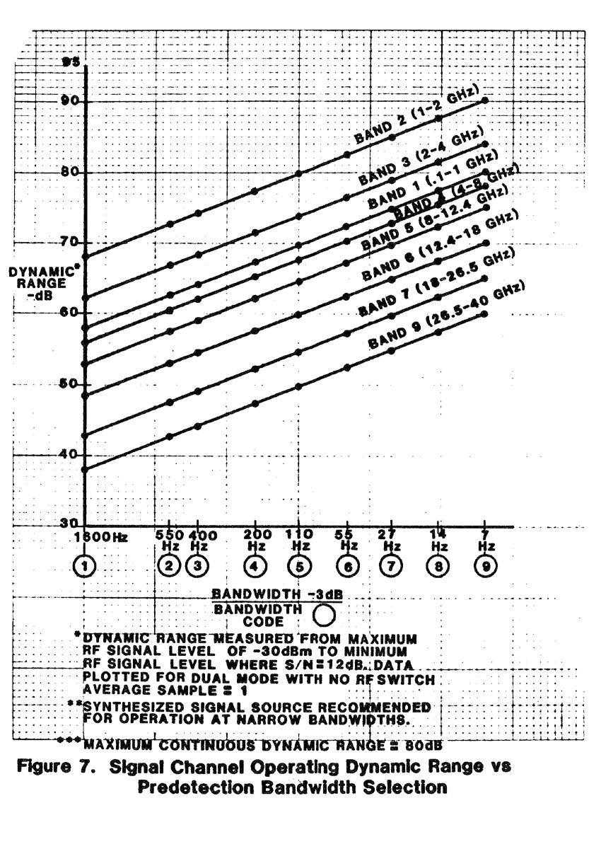
11 TABLE 2 PREDETECTION 3 db BANDWIDTH VS. BANDWIDTH CODE Bandwidth Code Predetection IF Bandwidth 3 db Hz Hz Hz Hz Hz 6 55 Hz 7 27 Hz 8 14 Hz 9 7 Hz Data averaging is possible by programming the receiver to average the measured data. Twelve AVERAGE SAMPLE levels are possible (1 through 12). Data averaging does not lower the system noise floor as does a bandwidth reduction; however, data averaging will reduce noise fluctuations, resulting in a smoothed average of the received data. The number of data samples averaged shown with the available AVERAGE SAMPLE choices is shown by Table 3. TABLE 3 POST DETECTION 3 db BANDWIDTH VS. AVERAGE SAMPLES CODE Average Sample Code No. of Samples Averaged Post Detection Bandwidth 3 db Hz Hz Hz Hz Hz Hz Hz Hz Hz Hz Hz Hz The versatility afforded by the ability to program the receiver BANDWIDTH is illustrated by Figure 7. This is a plot of the operating dynamic range of the signal channel versus selections of bandwidth for one averaged data sample. As shown, the receiver can be programmed to function as a high-data-rate acquisition system (BANDWIDTHS 1, 2, or 3), a moderate data-rate acquisition system (BANDWIDTHS 4 through 6) or a low-datarate, wide dynamic range system (BANDWIDTHS 7, 8 or 9).
12
13 IF SYSTEM The IF modules of the Series 1780 receiver have been designed using integrated circuit amplifiers as the basic amplifier gain stages. All main IF amplifiers are powered from power sources that are double-regulated. These design factors have resulted in an IF system with excellent gain and phase stability versus temperature and power line voltage change and phase-tracking between channels. The phase and amplitude stability of the IF system is further improved by a programmable calibration procedure. A stable, coherent MHz signal is supplied to the inputs of the SIG CH and APC CH IF preamplifiers as a calibration reference. An automatic calibration routine calibrates phase and amplitude of each IF channel in onedb amplitude steps over a 40-dB dynamic range. Error correction is performed digitally. The entire calibration procedure for three amplitude channels and two phase channels is accomplished in approximately ten seconds. Each IF channel and corresponding amplitude data output has a continuous operating dynamic range of 80 db with an 0.01 db resolution over the full 80 db dynamic range. The resolution of the phase data readout is 0.1 degree. The attenuation of each IF channel is programmable in 1.0 db steps over a 40 db dynamic range. Programmable phase presets and amplitude presets permit amplitude and phase channel output data to be preset to desired reference levels. An AUTO ZERO procedure automatically adjusts the output reading of any phase or amplitude channel to full scale (00.00 db log amplitude or degrees phase). SUMMARY The new Series 1780 Programmable Phase/Amplitude Receiver is a versatile microprocessor-based data acquisition receiver offering many new features and capabilities including IEEE-488 standard bus compatibility, high data rate capability, programmable IF system bandwidth, programmable data averaging, programmable IF system calibration, improved amplitude and phase stability, and an 80 db continuous dynamic range with a.01 db resolution. These features allow the receiver to be programmed to provide optimum performance for a wide variety of manual and automatic antenna range measurement situations.
A HIGH SPEED MICROWAVE MEASUREMENT RECEIVER
 A HIGH SPEED MICROWAVE MEASUREMENT RECEIVER William L. Tuttle ABSTRACT In order to justify the expenditure for capital equipment such as a microwave receiver, it must be shown that the instrument provides
Agilent 8360B/8360L Series Synthesized Swept Signal/CW Generators 10 MHz to 110 GHz
 Agilent 8360B/8360L Series Synthesized Swept Signal/CW Generators 10 MHz to 110 GHz ity. l i t a ers V. n isio c e r P. y t i l i ib Flex 2 Agilent 8360 Synthesized Swept Signal and CW Generator Family
SIGNAL RECOVERY. Model 7265 DSP Lock-in Amplifier
 Model 7265 DSP Lock-in Amplifier FEATURES 0.001 Hz to 250 khz operation Voltage and current mode inputs Direct digital demodulation without down-conversion 10 µs to 100 ks output time constants Quartz
Agilent PSA Series Spectrum Analyzers Self-Guided Demonstration for Phase Noise Measurements
 Agilent PSA Series Spectrum Analyzers Self-Guided Demonstration for Phase Noise Measurements Product Note This demonstration guide is a tool to help you gain familiarity with the basic functions and important
FREQUENCY AGILE FM MODULATOR INSTRUCTION BOOK IB
 FMT615C FREQUENCY AGILE FM MODULATOR INSTRUCTION BOOK IB1215-02 TABLE OF CONTENTS SECTION SUBJECT 1.0 Introduction 2.0 Installation & Operating Instructions 3.0 Specification 4.0 Functional Description
100 Hz to 22. HP 8566B Spectrum Analyzer. Discontinued Product Support Information Only. Outstanding Precision and Capability
 Discontinued Product Support Information Only This literature was published years prior to the establishment of Agilent Technologies as a company independent from Hewlett-Packard and describes products
GT 9000 GT 9000S MICROWAVE
 Page 1 of 6 GT 9000 GT 9000S MICROWAVE Now you can get the performance you need and the capability you want, at a price you can afford. Both the Giga-tronics GT9000 Microwave Synthe- techniques.together,
Model 855 RF / Microwave Signal Generator
 Features Very low phase noise Fast switching Phase coherent switching option 2 to 8 phase coherent outputs USB, LAN, GPIB interfaces Applications Radar simulation Quantum computing High volume automated
A COMPACT, AGILE, LOW-PHASE-NOISE FREQUENCY SOURCE WITH AM, FM AND PULSE MODULATION CAPABILITIES
 A COMPACT, AGILE, LOW-PHASE-NOISE FREQUENCY SOURCE WITH AM, FM AND PULSE MODULATION CAPABILITIES Alexander Chenakin Phase Matrix, Inc. 109 Bonaventura Drive San Jose, CA 95134, USA achenakin@phasematrix.com
FlexDDS-NG DUAL. Dual-Channel 400 MHz Agile Waveform Generator
 FlexDDS-NG DUAL Dual-Channel 400 MHz Agile Waveform Generator Excellent signal quality Rapid parameter changes Phase-continuous sweeps High speed analog modulation Wieserlabs UG www.wieserlabs.com FlexDDS-NG
Fundamentals of Microwave Frequency Counters. Application Note Electronic Counters Series
 H Fundamentals of Microwave Frequency Counters Application Note 200-1 Electronic Counters Series 1 Table of Contents Down-Conversion Techniques for Automatic Microwave Frequency Counters... 3 Prescaling...
FREQUENCY SYNTHESIZERS, SIGNAL GENERATORS
 SYNTHESIZED SIGNAL GENERATOR MG3641A/MG3642A 12 khz to 1040/2080 MHz NEW New Anritsu synthesizer technology permits frequency to be set with a resolution of 0.01 Hz across the full frequency range. And
RF Locking of Femtosecond Lasers
 RF Locking of Femtosecond Lasers Josef Frisch, Karl Gumerlock, Justin May, Steve Smith SLAC Work supported by DOE contract DE-AC02-76SF00515 1 Overview FEIS 2013 talk discussed general laser locking concepts
AV3672 Series Vector Network Analyzer
 AV3672 Series Vector Network Analyzer AV3672A/B/C/D/E (10MHz 13.5 GHz/26.5 GHz/43.5 GHz/50 GHz/67 GHz) Product Overview: AV3672 series vector network analyzer include AV3672A (10MHz 13.5GHz), AV3672B (10MHz
DSI-600 EMI Test & Measurement Receiver
 DSI-600 EMI Test & Measurement Receiver Product Brochure DSI-600 EMI TEST & Measurement Receiver Product Brochure December 2017 Dynamic Sciences International, Inc. DSI 600 Series EMI Test & Measurement
Advances in Antenna Measurement Instrumentation and Systems
 Advances in Antenna Measurement Instrumentation and Systems Steven R. Nichols, Roger Dygert, David Wayne MI Technologies Suwanee, Georgia, USA Abstract Since the early days of antenna pattern recorders,
Radio Receivers. Al Penney VO1NO
 Radio Receivers Al Penney VO1NO Role of the Receiver The Antenna must capture the radio wave. The desired frequency must be selected from all the EM waves captured by the antenna. The selected signal is
Phase Noise Measurement Personality for the Agilent ESA-E Series Spectrum Analyzers
 Phase Noise Measurement Personality for the Agilent ESA-E Series Spectrum Analyzers Product Overview Now the ESA-E series spectrum analyzers have one-button phase noise measurements, including log plot,
PN9000 PULSED CARRIER MEASUREMENTS
 The specialist of Phase noise Measurements PN9000 PULSED CARRIER MEASUREMENTS Carrier frequency: 2.7 GHz - PRF: 5 khz Duty cycle: 1% Page 1 / 12 Introduction When measuring a pulse modulated signal the
Signal Analysis Measurement Guide
 Signal Analysis Measurement Guide Agilent Technologies EMC Series Analyzers This guide documents firmware revision A.08.xx This manual provides documentation for the following instruments: E7401A (9 khz-
ECE 2111 Signals and Systems Spring 2009, UMD Experiment 3: The Spectrum Analyzer
 ECE 2111 Signals and Systems Spring 2009, UMD Experiment 3: The Spectrum Analyzer Objective: Student will gain an understanding of the basic controls and measurement techniques of the Rohde & Schwarz Handheld
9 Best Practices for Optimizing Your Signal Generator Part 2 Making Better Measurements
 9 Best Practices for Optimizing Your Signal Generator Part 2 Making Better Measurements In consumer wireless, military communications, or radar, you face an ongoing bandwidth crunch in a spectrum that
CUSTOM INTEGRATED ASSEMBLIES
 17 CUSTOM INTEGRATED ASSEMBLIES CUSTOM INTEGRATED ASSEMBLIES Cougar offers full first-level integration capabilities, providing not just performance components but also full subsystem solutions to help
HF Receivers, Part 2
 HF Receivers, Part 2 Superhet building blocks: AM, SSB/CW, FM receivers Adam Farson VA7OJ View an excellent tutorial on receivers NSARC HF Operators HF Receivers 2 1 The RF Amplifier (Preamp)! Typical
AVL-10000T AUDIO VIDEO LINK TRANSMITTER TECHNICAL MANUAL
 AVL-10000T AUDIO VIDEO LINK TRANSMITTER TECHNICAL MANUAL Document : AVL-10000T Version: 1.00 Author: Henry S Date: 25 July 2008 This module contains protection circuitry to guard against damage due to
SDI. Table of Contents
 NMSC-2 User Manual 2 Table of Contents Introduction........ 4 Hardware Installation.... 5 NMSC Power On.. 8 Overview... 9 FFT Measurement Screen.. 10 FFT Setup..... 11 FFT Detector..... 14 FFT Calibration.....
Radio Receivers. Al Penney VO1NO
 Radio Receivers Role of the Receiver The Antenna must capture the radio wave. The desired frequency must be selected from all the EM waves captured by the antenna. The selected signal is usually very weak
ExacTime GPS Time & Frequency Generator
 TIMING, TEST & MEASUREMENT ExacTime 6000 GPS Time & Frequency Generator KEY FEATURES GPS Time and Frequency Reference Disciplined Quartz Oscillator Time Base Optional Disciplined Rubidium Oscillator Rapid
Frequency and Time Domain Representation of Sinusoidal Signals
 Frequency and Time Domain Representation of Sinusoidal Signals By: Larry Dunleavy Wireless and Microwave Instruments University of South Florida Objectives 1. To review representations of sinusoidal signals
Model 745 Series. Berkeley Nucleonics Test, Measurement and Nuclear Instrumentation since Model 845-HP Datasheet BNC
 Model 845-HP Datasheet Model 745 Series Portable 20+ GHz Microwave Signal Generator High Power +23dBM Power Output 250 fs Digital Delay Generator BNC Berkeley Nucleonics Test, Measurement and Nuclear Instrumentation
Agilent X-Series Signal Analyzer This manual provides documentation for the following X-Series Analyzer: CXA Signal Analyzer N9000A
 Agilent X-Series Signal Analyzer This manual provides documentation for the following X-Series Analyzer: CXA Signal Analyzer N9000A N9000A CXA Functional Tests Notices Agilent Technologies, Inc. 2006-2008
2026Q CDMA/GSM Interferer MultiSource Generator
 Signal Sources 2026Q CDMA/GSM Interferer MultiSource Generator The 2026Q is designed to work with a radio test set to provide a fully integrated radio receiver test solution for cellular and PCS systems
DSA700 Series Spectrum Analyzer
 DSA700 Series Spectrum Analyzer Product Features: All-Digital IF Technology Frequency Range from 100 khz up to 1 GHz Min. -155 dbm Displayed Average Noise Level (Typ.) Min.
Agilent Technologies PSA Series Spectrum Analyzers Test and Adjustment Software
 Test System Overview Agilent Technologies PSA Series Spectrum Analyzers Test and Adjustment Software Test System Overview The Agilent Technologies test system is designed to verify the performance of the
USER OPERATION AND MAINTENANCE MANUAL
 46 Robezu str. LV-1004 Riga Latvia Phone: +371-7-065-100, Fax: +371-7-065-102 Mm-wave Division in St. Petersburg, Russia Phone: +7-812-326-5924, Fax: +7-812-326-1060 USER OPERATION AND MAINTENANCE MANUAL
EM-7530 Meter, Magnetic Field Strength
 EM-7530 Meter, Magnetic Field Strength Specifications Electrical Special Features Full operation from either front-panel controls or from computer via GPIB for maximum versatility. Special compact highly-sensitive
RC3000 Antenna Controller Appendix ASC Integrated ASC Beacon Receiver. Appendix ASC. Integrated ASC Beacon Receiver Option
 Revision: 5 December 2012, software version 1.60 Appendix ASC Integrated ASC Beacon Receiver Option This appendix describes the additional functions provided by the RC3000's integrated Atlantic Satellite
Antenna and RCS Measurement Configurations Using Agilent s New PNA Network Analyzers
 Antenna and RCS Measurement Configurations Using Agilent s New PNA Network Analyzers John Swanstrom, Application Engineer, Agilent Technologies, Santa Rosa, CA Jim Puri, Applications Engineer, Agilent
Technical Equipment Specification
 STATE OF CALIFORNIA Office of the State Chief Information Officer Public Safety Communications Division Technical Equipment Specification Equipment Type: Transmitter/Receiver Mobile Relay/Base/Control
PXA Configuration. Frequency range
 Keysight Technologies Making Wideband Measurements Using the Keysight PXA Signal Analyzer as a Down Converter with Infiniium Oscilloscopes and 89600 VSA Software Application Note Introduction Many applications
of Switzerland Analog High-Speed Products
 of Switzerland Analog High-Speed Products ANAPICO PRODUCTS 2012/2013 www.anapico.com Anapico Inc. is a growing Swiss manufacturer of leading edge products for RF test & measurement. The product ranges
FS5000 COMSTRON. The Leader In High Speed Frequency Synthesizers. An Ideal Source for: Agile Radar and Radar Simulators.
 FS5000 F R E Q U E N C Y S Y N T H E S I Z E R S Ultra-fast Switching < 200 nsec Wide & Narrow Band Exceptionally Clean An Ideal Source for: Agile Radar and Radar Simulators Radar Upgrades Fast Antenna
Fabricate a 2.4-GHz fractional-n synthesizer
 University of Malaya From the SelectedWorks of Professor Mahmoud Moghavvemi Summer June, 2013 Fabricate a 2.4-GHz fractional-n synthesizer H Ameri Mahmoud Moghavvemi, University of Malaya a Attaran Available
Configuration of PNA-X, NVNA and X parameters
 Configuration of PNA-X, NVNA and X parameters VNA 1. S-Parameter Measurements 2. Harmonic Measurements NVNA 3. X-Parameter Measurements Introducing the PNA-X 50 GHz 43.5 GHz 26.5 GHz 13.5 GHz PNA-X Agilent
Agilent E8267C/E8257C/E8247C PSG
 Agilent E8267C/E8257C/E8247C PSG Application Note Obtain flat-port power with Agilent s PSG user flatness correction or external leveling functions E8247C PSG CW signal generator Agilent E8244A E8257C
Troubleshooting Common EMI Problems
 By William D. Kimmel, PE Kimmel Gerke Associates, Ltd. Learn best practices for troubleshooting common EMI problems in today's digital designs. Industry expert William Kimmel of Kimmel Gerke Associates
Specification RIGOL. 6 Specification
 Specification RIGOL 6 Specification This chapter lists the specifications and general specifications of the analyzer. All the specifications are guaranteed when the following conditions are met unless
Spectrum Analyzer R&S FS300
 Spectrum Analyzer R&S FS300 9 khz to 3 GHz The new product family from Rohde & Schwarz Professional test equipment for laboratory, service and production The R&S FS300 is a highly accurate spectrum analyzer
PM 6669 High-Precision Frequency Counter Specifications
 PM 6669 High-Precision Frequency Counter Specifications Product Home Features Specifications Models, Options & Accessories Measuring functions Definitions Input specifications Auxiliary functions TimeBase
Agilent 8645 Signal Generator Communication. Product Note
 Agilent 8645 Signal Generator Communication Product Note 8645-2 A catalog of 8645A information This product note is actually a compilation of many brief product notes, each concerned with a particular
Glossary of VCO terms
 Glossary of VCO terms VOLTAGE CONTROLLED OSCILLATOR (VCO): This is an oscillator designed so the output frequency can be changed by applying a voltage to its control port or tuning port. FREQUENCY TUNING
WIDEBAND MICROWAVE SIGNAL GENERATOR. SG24000H Compact, Low Phase-Noise, Wideband. Signal Generator Control
 DS Instruments Key Features: 0.1 to 24GHz Coverage 25 Output Step Attenuator 20 Vernier Range D text S SG24000H WIDEBAND MICROWAVE SIGNAL GENERATOR Tiny Frequency Step Size Sub-Harmonic Filtering Very
8 Hints for Better Spectrum Analysis. Application Note
 8 Hints for Better Spectrum Analysis Application Note 1286-1 The Spectrum Analyzer The spectrum analyzer, like an oscilloscope, is a basic tool used for observing signals. Where the oscilloscope provides
Agilent Antenna and RCS Measurement Configurations Using PNA Microwave Network Analyzers. White Paper
 Agilent Antenna and RCS Measurement Configurations Using PNA Microwave Network Analyzers White Paper Abstract As technology changes, new and different techniques for measuring and characterizing antenna
Measurements 2: Network Analysis
 Measurements 2: Network Analysis Fritz Caspers CAS, Aarhus, June 2010 Contents Scalar network analysis Vector network analysis Early concepts Modern instrumentation Calibration methods Time domain (synthetic
DIGITAL MULTIMETERS VIEW RECORDERS & 7562 Digital Multimeters FUNCTIONS FEATURES
 756 & 7562 Digital Multimeters 756 (6-/2 digits) 23 88 330 mm 3 kg (8-3/8 3-/2 3" 6.6 lbs) 7562 (6-/2 digits) 23 88 330 mm 3 kg (8-3/8 3-/2 3" 6.6 lbs) The 7560 (6-/2 digit display) Series is a high-accuracy,
Low voltage LNA, mixer and VCO 1GHz
 DESCRIPTION The is a combined RF amplifier, VCO with tracking bandpass filter and mixer designed for high-performance low-power communication systems from 800-1200MHz. The low-noise preamplifier has a
Lab Exercise PN: Phase Noise Measurement - 1 -
 Lab Exercise PN: Phase Noise Measurements Phase noise is a critical specification for oscillators used in applications such as Doppler radar and synchronous communications systems. It is tricky to measure
TS9050/60. microgen. electronics TM FM Modulation and Spectrum Analyser
 TS9050/60 FM Modulation and Spectrum Analyser Introducing the TS9050 and TS9060, new and updated versions of the TS9000 NAB2004 Radio World Cool Stuff and The Radio Magazine Pick Hit award winner TS9050
8 Hints for Better Spectrum Analysis. Application Note
 8 Hints for Better Spectrum Analysis Application Note 1286-1 The Spectrum Analyzer The spectrum analyzer, like an oscilloscope, is a basic tool used for observing signals. Where the oscilloscope provides
Agilent 8360B Series Synthesized Swept Signal Generators 8360L Series Synthesized Swept CW Generators Data Sheet
 Agilent 8360B Series Synthesized Swept Signal Generators 8360L Series Synthesized Swept CW Generators Data Sheet 10 MHz to 110 GHz Specifications apply after full user calibration, and in coupled attenuator
DSA800. No.1 RIGOL TECHNOLOGIES, INC.
 No.1 DSA800 9 khz to 1.5 GHz Frequency Range Typical -135 dbm Displayed Average Noise Level (DANL) -80 dbc/hz @10 khz offset Phase Noise Total Amplitude Uncertainty
LadyBug LB5900 Programmatic Measurement Commands and Examples
 Contents Section I Programmatic Measurements Overview... 2 General... 2 Document Notice... 2 Zeroing and Calibration... 2 Sensing Range... 2 Section II - Non-Triggered Measurements... 3 READ? (Non-Triggered)...
Section 8. Replacing or Integrating PLL s with DDS solutions
 Section 8. Replacing or Integrating PLL s with DDS solutions By Rick Cushing, Applications Engineer, Analog Devices, Inc. DDS vs Standard PLL PLL (phase-locked loop) frequency synthesizers are long-time
Introduction. In the frequency domain, complex signals are separated into their frequency components, and the level at each frequency is displayed
 SPECTRUM ANALYZER Introduction A spectrum analyzer measures the amplitude of an input signal versus frequency within the full frequency range of the instrument The spectrum analyzer is to the frequency
87415A microwave system amplifier A microwave. system amplifier A microwave system amplifier A microwave.
 20 Amplifiers 83020A microwave 875A microwave 8308A microwave 8307A microwave 83006A microwave 8705C preamplifier 8705B preamplifier 83050/5A microwave The Agilent 83006/07/08/020/050/05A test s offer
Signal Generators for Anritsu RF and Microwave Handheld Instruments
 Measurement Guide Signal Generators for Anritsu RF and Microwave Handheld Instruments BTS Master Spectrum Master Tracking Generator Option 20 Vector signal Generator Option 23 Anritsu Company 490 Jarvis
LBI-31564A. Mobile Communications. DELTA - SX MHz RADIO COMBINATIONS (NEGATIVE GROUND ONLY) Maintenance Manual
 Maintenance Manual") A Mobile Communications DELTA - SX 136-174 MHz RADIO COMBINATIONS (NEGATIVE GROUND ONLY) Maintenance Manual TABLE OF CONTENTS MILITARY AND SYSTEM SPECIFICATIONS................................. 2-3 COMBINATION
A Mobile Communications DELTA - SX 136-174 MHz RADIO COMBINATIONS (NEGATIVE GROUND ONLY) Maintenance Manual TABLE OF CONTENTS MILITARY AND SYSTEM SPECIFICATIONS................................. 2-3 COMBINATION
Boulder W Class A Stereo Power Amplifier
 Boulder 2060 600 W Class A Stereo Power Amplifier Owners Manual V1.0 10/10/97 TABLE OF CONTENTS GETTING STARTED Placement of the 2050 Power amplifier......................................... 1-1 Connecting
Agilent AN 1275 Automatic Frequency Settling Time Measurement Speeds Time-to-Market for RF Designs
 Agilent AN 1275 Automatic Frequency Settling Time Measurement Speeds Time-to-Market for RF Designs Application Note Fast, accurate synthesizer switching and settling are key performance requirements in
FREQUENCY SYNTHESIZERS, SIGNAL GENERATORS
 SYNTHESIZED SWEEP/SIGNAL GENERATOR 69A, 68B series 10 MHz to 6 GHz GPIB A microwave synthesizer for any application Anritsu Wiltron s El Toro microwave synthesizers present 80 models, providing you the
Model Hz to 10MHz Precision Phasemeter. Operating Manual
 Model 6610 1Hz to 10MHz Precision Phasemeter Operating Manual Service and Warranty Krohn-Hite Instruments are designed and manufactured in accordance with sound engineering practices and should give long
THE SHIPBOARD ANTENNA TRACKING SYSTEM OF TELEMETRY
 THE SHIPBOARD ANTENNA TRACKING SYSTEM OF TELEMETRY Gao Quan Hui Principal engineer Beijing Research Institute Of Telemetry Beijing, P. R. China ABSTRACT This paper describes a C band auto tracking receiving
HF Receivers, Part 3
 HF Receivers, Part 3 Introduction to frequency synthesis; ancillary receiver functions Adam Farson VA7OJ View an excellent tutorial on receivers Another link to receiver principles NSARC HF Operators HF
Chapter 5 Specifications
 RIGOL Specifications are valid under the following conditions: the instrument is within the calibration period, is stored for at least two hours at 0 to 50 temperature and is warmed up for 40 minutes.
Agilent CSA Spectrum Analyzer
 Agilent CSA Spectrum Analyzer N1996A Exceptional performance... anytime, anywhere Frequency coverage Frequency range: 100 khz to 3 or 6 GHz Signal source: 10 MHz to 3 or 6 GHz Preamplifier to 3 or 6 GHz
Phase Matrix, Inc. 545B 548B. Phase Matrix, Inc. EIP 545B and 548B CW Frequency Counters. Instruments You Can Count On
 Phase Matrix, Inc. Instruments You Can Count On 545B 548B Phase Matrix, Inc. EIP 545B and 548B CW Frequency Counters Full Function CW Microwave Frequency Counters with Selective Power Measurement Keyboard
DIGITAL MULTIMETERS 7561 & & 7562 Digital Multimeters FEATURES RECORDERS INDEX
 756 & 7562 756 & 7562 Digital Multimeters 756 (6-/2 digits) 23 88 330 mm 3 kg (8-3/8 3-/2 3" 6.6 lbs) 7562 (6-/2 digits) 23 88 330 mm 3 kg (8-3/8 3-/2 3" 6.6 lbs) The 7560 (6-/2 digit display) Series is
Advanced Test Equipment Rentals ATEC (2832) MG3690B. RF/Microwave Signal Generators, 0.1 Hz to 70 GHz/325 GHz
 MG3690B. RF/Microwave Signal Generators, 0.1 Hz to 70 GHz/325 GHz") Established 1981 Advanced Test Equipment Rentals www.atecorp.com 800-404-ATEC (2832) MG3690B RF/Microwave Signal Generators, 0.1 Hz to 70 GHz/325 GHz MG3690B Family Signal Generators Easy to Read backlit
Established 1981 Advanced Test Equipment Rentals www.atecorp.com 800-404-ATEC (2832) MG3690B RF/Microwave Signal Generators, 0.1 Hz to 70 GHz/325 GHz MG3690B Family Signal Generators Easy to Read backlit
Specification for Conducted Emission Test
 1 of 10 1. EMI Receiver Frequency range 9kHz 7.0 GHz Measurement time per frequency 10 µs to 100 s time sweep, span = 0 Hz - 1 µs to 16000 s Sweep time in steps of 5 % frequency sweep, span 10 Hz - 2.5
Advanced Test Equipment Rentals ATEC (2832)
") Established 1981 Advanced Test Equipment Rentals www.atecorp.com 800-404-ATEC (2832) R3000 EMI TEST RECEIVERS Fully IF digital EMI Receivers family for measurement of electromagnetic interference from
Established 1981 Advanced Test Equipment Rentals www.atecorp.com 800-404-ATEC (2832) R3000 EMI TEST RECEIVERS Fully IF digital EMI Receivers family for measurement of electromagnetic interference from
Frequency Response Analyzers for Stability Analysis and Power Electronics Performance Testing
 Frequency Response Analyzers for Stability Analysis and Power Electronics Performance Testing Product Features Since 1979, Venable Instruments has been focused on one goal: bringing the most versatile,
Preliminary features of the SDR-X receiver SDR-X , PowerSDR Winrad Winrad DDS SFDR SFDR AD995 AD99 1
 Preliminary features of the SDR-X receiver The SDR-X receiver, in its full version is capable of continuously tuning the entire HF spectrum, 6m ( 50-52 MHz) band included. SSB, AM etc. demodulation, bandpass
Heterodyne Sweeping Radiometer
 46 Robezu str. LV-1004 Riga, Latvia Fax: +371-7-065102 Mm-wave Division in St. Petersburg, Russia Fax: +7-812- 326-10-60 Tel: +7-812-326-59-24 E-mail: ivanovph@nnz.ru Heterodyne Sweeping Radiometer Operation
DEPARTMENT OF THE ARMY TECHNICAL BULLETIN
 *TB 9-6625-2333-24 DEPARTMENT OF THE ARMY TECHNICAL BULLETIN CALIBRATION PROCEDURE FOR SPECTRUM ANALYZER AGILENT MODELS 8562EC AND 8562EC-104 Headquarters, Department of the Army, Washington, DC 17 June
Keysight Technologies E8257D PSG Microwave Analog Signal Generator. Data Sheet
 Keysight Technologies E8257D PSG Microwave Analog Signal Generator Data Sheet 02 Keysight E8257D Microwave Analog Signal Generator - Data Sheet Table of Contents Specifications... 4 Frequency... 4 Step
MITIGATING INTERFERENCE ON AN OUTDOOR RANGE
 MITIGATING INTERFERENCE ON AN OUTDOOR RANGE Roger Dygert MI Technologies Suwanee, GA 30024 rdygert@mi-technologies.com ABSTRACT Making measurements on an outdoor range can be challenging for many reasons,
First Time User Manual
 Fiber Fabry-Perot Tunable Filter FFP-TF2 First Time User Manual Micron Optics Inc. 1852 Century Place NE Atlanta, GA 30345 USA phone 404 325 0005 fax 404 325 4082 www.micronoptics.com Copyright 2009 Micron
Varactor-Tuned Oscillators. Technical Data. VTO-8000 Series
 Varactor-Tuned Oscillators Technical Data VTO-8000 Series Features 600 MHz to 10.5 GHz Coverage Fast Tuning +7 to +13 dbm Output Power ± 1.5 db Output Flatness Hermetic Thin-film Construction Description
VHF LAND MOBILE SERVICE
 RFS21 December 1991 (Issue 1) SPECIFICATION FOR RADIO APPARATUS: VHF LAND MOBILE SERVICE USING AMPLITUDE MODULATION WITH 12.5 khz CARRIER FREQUENCY SEPARATION Communications Division Ministry of Commerce
SC5307A/SC5308A 100 khz to 6 GHz RF Downconverter. Datasheet SignalCore, Inc.
 SC5307A/SC5308A 100 khz to 6 GHz RF Downconverter Datasheet 2017 SignalCore, Inc. support@signalcore.com P RODUCT S PECIFICATIONS Definition of Terms The following terms are used throughout this datasheet
Icom IC-9100 HF/VHF/UHF transceiver
 263 Walsall Road, Great Wyrley, Walsall, WS6 6DL Established 1997. Open Monday - Friday 9am - 5pm and Saturday 9.30am - 4pm Tel: 01922 414 796 Fax: 01922 417829 Skype: radioworld_uk Icom IC-9100 HF/VHF/UHF
NACT TUTORIAL 3 FREQUENCY RESPONSE CALIBRATION
 Applies to: NAT and NACT MODES Prerequisites: Tutorials 0, 1, and 2 This tutorial takes you through the process of generating and capturing calibration data to account for variations in of the DDS output
Design Implementation Description for the Digital Frequency Oscillator
 Appendix A Design Implementation Description for the Frequency Oscillator A.1 Input Front End The input data front end accepts either analog single ended or differential inputs (figure A-1). The input
Agilent ESA-L Series Spectrum Analyzers
 Agilent ESA-L Series Spectrum Analyzers Data Sheet Available frequency ranges E4403B E4408B 9 khz to 1.5 GHz 9 khz to 3.0 GHz 9 khz to 26.5 GHz As the lowest cost ESA option, these basic analyzers are
Design considerations for the RF phase reference distribution system for X-ray FEL and TESLA
 Design considerations for the RF phase reference distribution system for X-ray FEL and TESLA Krzysztof Czuba *a, Henning C. Weddig #b a Institute of Electronic Systems, Warsaw University of Technology,
Model 34A. 3Hz to 2MHz 2-Channel Butterworth/Bessel HP, LP, BP, BR Plug-In Filter Card for Model 3905/3916 Chassis.
 Model 34A 3Hz to 2MHz 2-Channel Butterworth/Bessel HP, LP, BP, BR Plug-In Filter Card for Model 3905/3916 Chassis Operating Manual Service and Warranty Krohn-Hite Instruments are designed and manufactured
DIGITAL BEAM-FORMING ANTENNA RANGE
 DIGITAL BEAM-FORMING ANTENNA RANGE Masahiro Tanabe Toshiba Corporation Komukai Works 1, Komukai, Toshiba-cho, Saiwai-ku, Kawaski, 210-8581 Japan (044)548-5255 msahiro.tanabe@toshiba.co.jp Davd S. Fooshe
Obtaining Flat Test Port Power with the Agilent 8360 s User Flatness Correction Feature. Product Note
 Obtaining Flat Test Port Power with the Agilent 8360 s User Flatness Correction Feature Product Note 8360-2 Introduction The 8360 series synthesized sweepers provide extremely flat power at your test port,
MAINTENANCE MANUAL TRANSMITTER/RECEIVER BOARD CMN-234A/B FOR MLSU141 & MLSU241 UHF MOBILE RADIO TABLE OF CONTENTS
 MAINTENANCE MANUAL TRANSMITTER/RECEIVER BOARD CMN-234A/B FOR MLSU141 & MLSU241 UHF MOBILE RADIO TABLE OF CONTENTS DESCRIPTION... 2 CIRCUIT ANALYSIS... 2 TRANSMITTER... 2 9-Voft Regulator... 2 Exciter...