Model 34A. 3Hz to 2MHz 2-Channel Butterworth/Bessel HP, LP, BP, BR Plug-In Filter Card for Model 3905/3916 Chassis.
|
|
|
- Elwin Richard
- 5 years ago
- Views:
Transcription

1 Model 34A 3Hz to 2MHz 2-Channel Butterworth/Bessel HP, LP, BP, BR Plug-In Filter Card for Model 3905/3916 Chassis Operating Manual
2 Service and Warranty Krohn-Hite Instruments are designed and manufactured in accordance with sound engineering practices and should give long trouble-free service under normal operating conditions. If your instrument fails to provide satisfactory service and you are unable to locate the source of trouble, contact our Service Department at (508) , giving all the information available concerning the failure. DO NOT return the instrument without our written or verbal authorization to do so. After contacting us, we will issue a Return Authorization Number which should be referenced on the packing slip and purchase order. In most cases, we will be able to supply you with the information necessary to repair the instrument, avoiding any transportation problems and costs. When it becomes necessary to return the instrument to the factory, kindly pack it carefully and ship it to us prepaid. All Krohn-Hite products are warranted against defective materials and workmanship. This warranty applies for a period of one year from the date of delivery to the Original Purchaser. Any instrument that is found within the one year warranty period not to meet these standards, will be repaired or replaced. This warranty does not apply to electron tubes, fuses or batteries. No other warranty is expressed or implied. Krohn-Hite Corporation reserves the right to make design changes at any time without incurring any obligation to incorporate these changes in instruments previously purchased. Modifications to this instrument must not be made without the written consent of an authorized employee of Krohn-Hite Corporation.
 580-1660; Fax: (508) 583-8989 E-mail: Info@krohnhite.com; www.krohn-hite.")
3 MODEL 34A DUAL CHANNEL/BUTTERWORTH/BESSEL LOW-PASS/HIGH-PASS/BAND-PASS/BAND-REJECT PLUG-IN FILTER MODULE OPERATING MANUAL Serial No. Serial No. 15 Jonahtan Drive, Brockton, MA Tel: (508) ; Fax: (508)
4 2
5 TABLE OF CONTENTS 1.0 GENERAL DESCRIPTION INTRODUCTION SPECIFICATIONS OPERATION INTRODUCTION OPERATING PROCEDURE Channel Selection All Channel Key Procedure Cutoff Frequency Input Gain (Pre-Filter) Output Gain (Post Filter) Mode of Operation Filter Type Input Coupling Clear Entry Key Operation Storing Set-Ups Recalling Set-Ups Second Function Key Operation FILTER CHARACTERISTICS Introduction Variable Band-Pass and Band-Reject Operation Amplitude Response Phase Response Group Delay Transient Response IEEE-488 STD (GPIB) PROGRAMMING INTRODUCTION FILTER TYPE MODE OF OPERATION DEVICE CLEAR INCOMING ACCEPTANCE INTRODUCTION TEST EQUIPMENT REQUIRED FILTER CHARACTERISTICS Low Pass/High Pass Response Cutoff Frequency Accuracy Band-Pass/Band-Reject Response Stopband Attentuation* *(This procedure requires a Fluke Model 8920A voltmeter) Pre-Filter and Post-Filter Gain Accuracy Noise Check (This procedure requires a Fluke Model 8920A voltmeter) Distortion and Maximum Signal Checks AC/DC Coupling Check
6 NOTES 4
7 1.1 INTRODUCTION SECTION 1 GENERAL DESCRIPTION The Model 34A is a dual filter with two identical channels covering a tunable frequency range from 3Hz to 2MHz. Each channel can function independently with either low-pass or high-pass response at 24dB/octave attenuation or connected in series in the same mode to provide 48dB/octave attenuation. Band-pass or band-reject operation at 24dB/octave can be obtained. Either maximally flat (Butterworth) response or linear phase (Bessel) operation for pulse signal filtering is selectable. Both input and output amplifiers provide either 0dB or 20dB of gain. The Model 34A is a plug-in filter card which is operational only when inserted in the five-card Model 3905A/3905B/3905C or the sixteen-card Model 3916A/3916B/3916C Mainframe. Each Mainframe includes a microprocessor plug-in card; the Model 39A-05 for the 3905A/3905B/3905C, and the 39A-16 for the 3916A/3916B/3916C. The filter and microprocessor cards are easily accessible from the rear of the Mainframe. The filer is controlled by the Mainframe which provides local/ieee-488 programming, displays for the input and output gain, cutoff frequency and channel selection. Non-volatile, batterybacked, CMOS memory permits the storing and recalling of 85 selectable groups in the 3905A/3905B/3905C and 25 in the 3916A/3916B/3916C. Storing and recalling group settings is accomplished with only one command. Self-testing of the digital circuitry occurs upon power-up. This Operating and Maintenance Manual is for the Model 34A filter module only. A separate manual is provided for the Model 3905A/3905B/3905C or 3916A/3916B/3916C Mainframe. 1.2 SPECIFICATIONS FILTER CHARACTERISTICS Functions: two independent channels of low-pass, high-pass or by-pass; one channel of bandpass or band-reject. Type: 4-pole Butterworth (maximally flat) or Bessel (linear phase). Frequency Range (f c ): 3Hz to 2MHz Frequency Resolution: 1Hz from 3Hz to 1kHz; 10Hz up to 2kHz; 100Hz up to 100kHz; 1kHz up to 1MHz; 10kHz up to 2MHz. Frequency Accuracy (f c ): ±2% or least significant digit (which ever is greater) 20Hz to 500kHz; ±5% to 2MHz. Relative Gain at f c : Butterworth, -3dB; Bessel, -7.58dB. Bandwidth: dc to f c, dc coupled; 0.2HZ to f c, ac coupled (low-pass); f c to 10MHz (high-pass). Attenuation: 24B/octave per channel. Stopband Attenuation: >80dB. Insertion Loss (0dB Input/Output gain): ±0.5dB to 2MHz. 5
8 GAIN Input (pre-filter): 0dB or 20dB ±0.2dB. Output (post-filter): 0dB or 20dB ±0.2dB. INPUT Coupling: ac or dc. Impedance: 1 megohm in parallel with <30pf (<100pf in a Model 3905B with front panel BNC s). Maximum Signal (at 0dB gain): ±4.5V peak at f c <1MHz; ±4V peak at 2MHz. Maximum DC Component: ±200V in ac coupled mode. OUTPUT Impedance: 50 ohms. Maximum Voltage: ±6.5V peak into >500 ohms; ±1.3V peak into >50 ohms. Maximum Current: ±25mA. Distortion: -80dB at 1kHz at 1V rms. Noise (RTI): <200µV with 2MHz bandwidth detector (20µV w2ith 20dB input gain). DC Offset: adjustable to 0V. DC Stability: ±1mV/ C. Input/Output Connectors: BNC. Phase Match Between Channels*: 1 to 500kHz f c (Bessel only); 2 to 1MHz; 3 to 2MHz (max difference between any two channels). GENERAL Power: 15 watts. Weight: 1.75 lbs. (0.8kg) net. Operating Temperature: 0 to 45 C. Specifications apply at 25 C ±10C, 20Hz to 2MHz. *For cards in same chassis, otherwise consult factory. 6
9 SECTION 2 OPERATION 2.1 INTRODUCTION The Model 34A is a dual filter covering the frequency range from 3Hz to 2MHz. It is one of a series of plug-in filter cards available for the five-card Model 3905A/3905B/3905C or the sixteen-card Model 3916A/3916B/3916C Mainframes. All filter parameters are programmable via the Mainframe front panel controls or remotely over the IEEE-488 (GPIB) bus. For information on remote programming, refer to Section 3 of the Model 3905A/3905B or 3916A/3916B Operating and Instruction Manual and Section 3 of this manual. Either channel of the 34A can operate independently in either the low-pass or high-pass mode and provide 24dB/octave attenuation. The two channels can be connected in series externally in the same mode to attain 48dB/octave attenuation when set to the same cutoff frequency. If the two channels are interconnected externally with one channel set to high-pass and the other to low-pass, the filter will now function as a band-pass filter, passing the band of frequencies selected by the high and low cutoff frequencies. If the two channels are interconnected externally using a band-reject kit (BR-30), the filter will then function as a band-reject filter, rejecting the band selected by the high and low cutoff frequencies. 2.2 OPERATING PROCEDURE Channel Selection Up and down controls [ ] and [ ] increase or decrease channel setting shown on the DISPLAY. When held, channels will cycle through all active channels continuously. Channel selection can also be accomplished by entering the desired channel number in the keyboard and momentarily pressing either up [ ] or down [ ] channel controls All Channel Key Procedure When frequency, input/output gain, type, mode or coupling are entered or changed, and the LED in the [ALL CHAN] key is on, the new setting will also be entered in all other filters of the same card type Cutoff Frequency Data entry keyboard controls [0] to [9] and [.] set the numeric value of the cutoff frequency desired. To program 1.5kHz press the [1][.][5] data keys and parameter keys [KILO] and [FREQ]. The cutoff frequency will be entered only in the channel displayed and indicated in Hertz in the four digit DISPLAY. 7
10 2.2.4 Input Gain (Pre-Filter) Up and down GAIN SET controls [ ] and [ ] increase or decrease the input amplifier by 20dB. The two digit DISPLAY will indicate either 00 or 20dB Output Gain (Post-Filter) Up and down GAI SET controls [ ] and [ ] increase or decrease the output amplifier by 20dB. The two digit DISPLAY will indicate either 00 or 20dB Mode of Operation When the [MODE] key is pressed, the DISPLAY indicates the mode of operation in the channel displayed, alternating as the [MODE] key is pressed between low-pass L.P., high-pass h.p., band-pass b.p., band-reject b.r. and by-pass byp. which connect input to output Filter Type The DISPLAY will indicate the filter type in the channel displayed when the [TYPE] key is pressed, alternating between Butterworth bu. and Bessel bes. response Input Coupling Pressing the [SECONF FUNCTN] key followed by the [TYPE] key will display the input coupling, indicating AC or dc, and will alternate when the two key are pressed again only when in the low-pas and band-reject mode. High-pass and band-pass mode are AC only Clear Entry Key Operation When entering a numeric value in the keyboard, but not specifying a parameter, pressing the clear entry key will function as an error correction procedure and restore DISPLAY to its previous set-up. When a numeric value and its parameter has been entered and the numeric value is then changed, pressing the [CE] key will restore DISPLAY to the previous value of that parameter. When either the [SECOND FUNCTN][STORE] or [RECALL] key is pressed, the next memory location will be indicated on the DISPLAY. Pressing the [CE] key will restore DISPLAY to its previous setting. When the DISPLAY contains information other than the frequency, pressing the [CE] key will restore the DISPLAY to the current frequency. If the Model 3905B or 3916B is operating via the IEEE-488 bus (the front panel REMOTE LED is on ), pressing the [CE] key will return unit to LOCAL operation. 8
11 Storing Set-Ups If a memory location is entered into the keyboard, pressing the [SECOND FUNCTN][STORE] key will store the entire five card (Model 3905B) or sixteen card (Model 3916B) set-ups into the memory location selected. The maximum number of memory locations is 85 in the Model 3905B and 25 in the Model 3916B. When the [SECOND FUNCTN][STORE] key is first pressed, the DISPLAY indicates the number of the next memory location available. For example, the DISPLAY will indicate the following: n=09. Pressing the [SECOND FUNTN][STORE] key again will store the set-up currently in all channels into that memory location. If another memory location is desired enter that location on the keyboard and then press the [SECOND FUNTN][STORE] key. When the [SECOND FUNCTN][STORE] key is pressed to indicate the next memory location only, pressing the clear entry key [CE] will restore the DISPLAY to the current frequency Recalling Set-Ups If a memory location is entered into the keyboard, pressing the [RECALL] key will recall the entire five (Model 3905B) or sixteen (Model 3916B) card set-ups from the memory location selected. When the [RECALL] key is first pressed, the DISPLAY indicates the number of the next memory location to be recalled. For example, the DISPLAY will indicate the following: n=09. Pressing the [RECALL] key again will recall the se-up of all five (Model 3905B) or sixteen (Model 3916B) cards from that memory location. When the [RECALL] key is pressed to indicate the next memory location to be recalled only, pressing the clear entry key [CE] will restore the DISPLAY back to the previous setting Second Function Key Operation The [SECOND FUNCTN] key in conjunction with other keys provides additional filter characteristics and permits GPIB front panel data entry. Pressing the [SECOND FUNCTN] key followed by the [AC/DC] key will display the input coupling, indicating AC or dc, and will alternate when the two keys are pressed again only in the low-pass and band-reject mode. High-pass and band-pass modes are AC only. When the [SECOND FUNCTN] key followed by the [ADDR] key are pressed, the DISPLAY will indicate the existing GPIB address setting. To select a different one, enter it in the data keys from [0] to [30] and press the [SECOND FUNCTN] and [ADDR] keys (See Section of the 3905B or 3916B manual). When the [SECOND FUNCTN] key followed by the [ALL CHAN] key are pressed, the DISPLAY will indicate the existing Line Termination Code Sequence. To select a different one, enter it in the data keys from [0] to [30] and press the [SECOND FUNCTN] and [ALL CHAN] keys (See Section of the 3905B or 3916B manual). 9
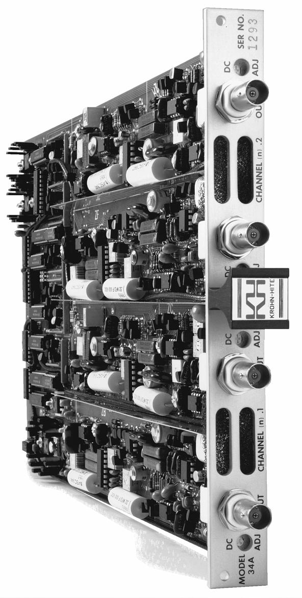
12 2.3 FILTER CHARACTERISTICS Introduction The Model 34A, as shown in Figure 2.1, is a dual filter with two identical channels that can function independently. Each channel can operate in either the low-pass mode or high-pass mode and provide 24dB/octave attenuation, or both channels can be set to the same mode and connected in series externally to obtain 48dB/octave attenuation. The interconnection of the two channels, by front panel data key entry, to provide band-pass, band-reject or null operation is shown in simplified format in Figures 2.2 and Variable Band-Pass and Band-Reject Operation Variable band-pas response is obtained by applying the input signal to channel n.1 (i.e. 1.1, 2.1, 3.1, etc.), setting the channel number to n.1, setting the filter to the band-pass mode b.p. using the [MODE] key, and entering the desired low-cutoff frequency. Set the filter to channel n.2 and enter the desired high-cutoff frequency. The band-pass response appears at the channel n.1 output BNC connector only. Note. In the band-pass mode, there is a phase shift of 180 from input to output. To achieve a 0 phase shift through the filter connected Channel n.1 output to Channel n.2 input externally, and set n.1 to high-pass and n.2 to low-pass. For band-reject response, set the filter to channel n.1, the band-reject mode to b.r and enter the desired low-cutoff frequency. Set the filter to channel n.2 and enter the desired high-cutoff frequency. A null can be obtained by setting the low cutoff frequency to approximately 0.58 of the desired null frequency, the high cutoff frequency to approximately 1.7 of the null frequency and fine tune both cutoff frequencies. The resolution of the Model 34A will limit the extent of the null. The channel 1.2 output is the high-pass section only Amplitude Response Each channel of the Model 34A can operate in either the low-pass or highpass mode at 24dB/octave attenuation and provide either maximally flat (Butterworth) amplitude response or linear phase (Bessel) operation. Comparative amplitude response characteristics in both modes are shown in Figure 2.4 and Figure 2.5. Figure 2.4 Low-Pas Response 10
13 Figure 2.5 High-Pass Response Phase Response Phase characteristics of the Model 34A are shown in Figure 2.6. It provides output phase relative to the input with the filter operating in the low-pass mode with Butterworth and Bessel response. Figure 2.6 Low-Pass Phase Response 11
14 2.3.5 Transient Response The normalized response for a unit step voltage applied to the input of the Model 34A operating in the low-pass mode with both Butterworth and Bessel response is shown in Figure 2.7. Figure 2.7 Normalized Step Response Group Delay Group delay 1, shown in Figure 2.8, is defined as the derivative of radian phase with respect to radian frequency, which is the slope of the phase curve. A flat group delay is considered a linear phase response which corresponds to a constant slope of the phase curve. With linear phase response the distortion of complex data signals will be minimized because their various frequency components, due to a constant time delay, will not shift relative phase Figure 2.8 Low-Pass Group Delay 12
15 In numeric terms, zero frequency phase slope is /Hz for Butterworth and /Hz for Bessel, when normalized for a cutoff frequency of 1Hz. This will be 2π times greater in /Hz for a cutoff of 1 radian/sec or /H and /Hz respectively. Dividing by 360, converts /Hz to radians/radians-per-sec yields a group delay time of 2.61s for Butterworth and 3.20s for Bessel. [1] IEEE Standard Dictionary of Electrical and Electronic Terms, Institute of Electrical and Electronic Engineers, IEEE-SDSTD , Second Edition, 1977, page
16 This Page Intentionally Left Blank. 14
17 SECTION 3 IEEE-488 STD (GPIB) PROGRAMMING 3.1 INTRODUCTION Complete information on remote programming is incorporated in the Model 3905B/3916B Mainframe operating and instruction manual. Detailed information about the filter type, modes of operation and device clear command not described in the 3905A/3905B/3905C or 3916A/3916B/3916C manual are specified below. 3.2 FILTER TYPE 1 Butterworth 2 Bessel 3.3 MODE OF OPERATION 1 Low-Pass 2 High-Pass 3 Band-Pass 4 Band-Reject 5 By-Pass 3.4 DEVICE CLEAR When the device clear command is sent the following parameters, irregardless of their existing setting, are set as follows: INPUT GAIN OUTPUT GAIN RESPONSE MODE CUTOFF FREQUENCY COUPLING 0dB 0dB Butterworth Low-Pass 100kHz AC 15
18 This Page Intentionally Left Blank 16
19 SECTION 4 INCOMING ACCEPTANCE 4.1 INTRODUCTION The following procedure should be used to verify that the Model 34A filter card, inserted in a Model 3905A/3905B/3905C or 3916A/3916B/3916C Mainframe, is operating within specifications. These checks may be used for incoming acceptance and periodic performance checks. Tests must be made with all covers in place on the Model 3905A/3905B/3905C or 3916A/3916B/3916C, with filter cards inserted, operating for a minimum tie of ½ hour to reach thermal equilibrium. If not operating within specifications refer to Section 5, Calibration, before attempting any detailed maintenance. Before testing, follow the initial set-up and operating procedure in Section2 of this manual and the Model 3905A/3905B/3905C or 3916A/3916B/3916C Operating and Maintenance Manual. 4.2 TEST EQUIPMENT REQUIRED The test equipment below is required to perform the following tests: a. Low Distortion RC Oscillator: Krohn-Hite Model 4400A or equivalent. b. RC Oscillator: 10Hz to 10MHz, frequency response of ±0.025dB from 10Hz to 500kHz. Krohn- Hite Model 4200B/4300B or equivalent. c. AC Voltmeter: capable of measuring 100µV to 10Vrms, 10MHz bandwidth, Fluke Model 8920A or equivalent. d. Frequency Counter. e. Distortion Analyzer: Krohn-Hite Model 6900B or equivalent. 4.3 FILTER CHARACTERISTICS Low Pass/High Pass Response The Model 34A has two independent channels in either the low-pass, high-pass or by-pass mode; or one channel in the band-pas or band-reject mode. Either Butterworth (maximally flat) or Bessel (linear phase) response is selectable. Set filter cutoff frequency to 1kHz in the low-pass mode L.P. with Butterworth response bu. and with 0dB Input and Output gain. Apply 1Vrms at 100Hz to the INPUT of the channel whose second digit ends in one (n.1). These settings can be entered into all cards of the same type simultaneously by pressing the [ALL CHAN] key (so its LED is on) prior to entering the above settings. When this LED is off, these settings will be entered only in the channel indicated in the channel DISPLAY. Monitor the OUTPUT of the filter with an ac voltmeter and record the OUTPUT voltage. Set the oscillator frequency to 1kHz. The OUTPUT voltage should be approximately 3db. Set the frequency to 2kHz. The OUTPUT voltage should be approximately 24dB. Set the filter to 17

20 Bessel response bes and repeat the above. The OUTPUT voltage should be approximately 7.6dB and 25.4dB respectively. Set the filter cutoff frequency to 1kHz in high-pass mode h.p. with Butterworth response and with 0dB Input and Output gain. Apply 1Vrms at 10kHz to the INPUT of the filter. Monitor the OUTPUT of the filter with an ac voltmeter and record the OUTPUT voltage. Set the oscillator frequency to 1kHz. The OUTPUT voltage should be approximately 3dB. Set the frequency to 500Hz. The OUTPUT voltage should be approximately 24dB. Set he filter to Bessel response and repeat the above. The OUTPUT voltage should be approximately 7.6dB and 25.4dB respectively. In the by-pass mode byp. the INPUT is connected directly to the OUTPUT. Monitor the INPUT and OUTPUT to verify this mode of operation Cutoff Frequency Accuracy Connect the oscillator at 1Vrms at 50Hz to the INPUT of a filter set to Butterworth response. Set the cutoff frequency to 1kHz in the low-pass mode wit 0dB Input and Output gain. Monitor the OUTPUT of the filter with a frequency counter and an ac voltmeter, and record the OUTPUT voltage. Set the oscillator to 1kHz and adjust its frequency so the OUTPUT voltage is 3dB. The oscillator frequency should be within ±2% of the cutoff frequency of 1kHz. Repeat above at a filter cutoff frequency of 100kHz, 500kHz and 1MHz. The tolerance should be within ±2% at 100kHz and 500kHz, and ±5% at 1MHz. Connect the oscillator at 1Vrms at 20kHz to the INPUT of the filter set to a cutoff frequency of 1kHz in the high-pass mode with 0dB Input and Output gain. Monitor the OUTPUT of the filter with a frequency counter and an ac voltmeter, and record the OUTPUT voltage. Set the oscillator to 1kHz and adjust its frequency so the OUTPUT voltage is 3dB. The oscillator frequency should be within ±2% of the cutoff frequency of 1kHz. Repeat above at a filter cutoff frequency of 100kHz, 500kHz and 1MHz. The tolerance should be within ±2% at 100kHz and 500kHz, and ±5% at 1MHz Band-Pass/Band-Reject Response Variable band-pass response shown in Figure 4.1, is obtained by applying the input signal to channel n.1 INPUT, setting the channel DISPLAY to channel n.1 (or any channel where the second digit ends in one) and setting the filter to the bandpass mode ( b.p. ). In the band-pass mode it is necessary that the [ALL CHAN] LED is off. Figure 4.1 Band-Pass Response 18
21 Set the filter to Butterworth response and apply 1Vrms at 10kHz to the INPUT of channel n.1 set to a low cutoff frequency of 1kHz. Set the filter to channel n.2 and the high cutoff frequency to 100kHz. Monitor the OUTPUT of channel n.1 with an ac voltmeter and record the voltage. Set the oscillator frequency to 1kHz and 100kHz. The OUTPUT voltage should be approximately 3dB at these frequencies. Set the oscillator frequency to 500Hz and 200kHz. The OUTPUT voltage should be approximately 24dB at these frequencies. Variable band-reject response, shown in Figure 4.2, is obtained by applying the input signal to channel n.1 INPUT and setting the filter to the band-reject mode ( b.r. ) with Butterworth response. Apply 1Vrms at 100Hz to the INPUT of channel n.1 and set the low cutoff frequency to 1kHz. Se the filter to channel n.2 and the high cutoff frequency to 100kHz. Monitor the OUTPUT of channel n.1 with an ac voltmeter and record the voltage. Set the oscillator frequency to 1kHz and 100kHz. The OUTPUT voltage should be approximately 3dB at these frequencies. Set the oscillator frequency to 2kHz and 50kHz. The OUTPUT voltage should be 24dB at these frequencies Stopband Attenuation Accurate stopband attenuation measurements require some simple precautions because of low level signals. The filter should be shielded with top and bottom covers of the Model 3905A/3905B or 3916A/3916B in place. BNC cables only should be used between oscillator, filter and voltmeter and no other instruments should be connected. Connect the oscillator at 3Vrms at 20kHz to the INPUT of the filter set to a cutoff frequency of 1kHz with 0dB Input and Output gain. Connect the OUTPUT of the filter through a 6kHz passive high-pass filter, as shown in Figure 4.3, to the AC Voltmeter. Set the filter to the lowpass mode. The filter OUTPUT should be <300µVrms (-80dB). Figure 4.3 High-Pass Filter Pre-Filter and Post-Filter Gain Accuracy Set the filter to a cutoff frequency of 1kHz in the low-pass mode with 0dB Input and Output gain and apply 50mVrms at 100Hz to the INPUT. Monitor the OUTPUT of the filter with an ac voltmeter and record the OUTPUT voltage. Set the GAIN of the pre-filter (Input) to 20dB. The OUTPUT of the filter should be a sinewave and within ±0.2dB of the pre-filter gain setting of 20dB. Set the gain of the pre-filter (Input) to zero 19
22 and the gain of the filter post-filter (Output) to 20dB. The OUTPUT of the filter should be a sinewave and within ±0.2dB of the post-filter gain settings of 20dB Noise Check Short the INPUT of the filter and set it to 0dB Input and Output gain, low-pass mode, Butterworth response at a cutoff frequency of 2MHz. Connect the OUTPUT of the filter using a shielded BNC cable in series with a 2MHz low-pass filter, shown in Figure 4.4, to the AC Voltmeter. Voltmeter reading should be <200µV. Set the cutoff frequency to 200kHz. Voltmeter reading should be <200µV. Set the filter to the high-pass mode at a cutoff frequency of 100Hz. Voltmeter reading should be <200µV. The 2MHz low-pass filter should be inserted in a shielded enclosure (Pomona Model 3231 or equivalent) and connected directly to the voltmeter. Nothing else should be connected to the filter and voltmeter. Figure 4.4 Low-Pass Filter Distortion and Maximum Signal Checks a. Set the filter to a cutoff frequency of 25.6kHz in the low-pass mode with 0dB Input and Output gain. Connect a low distortion oscillator to the Input and apply 1Vrms at 1kHz. Monitor the OUTPUT of the filter with a distortion analyzer. The distortion should be <0.01%. CAUTION! If the distortion is excessive, verify that the distortion of the oscillator being used is less than 0.005%. b. Connect a 50 ohm terminator to OUTPUT of the filter. Distortion should be <0.01%. Remove terminator. c. Set oscillator to 2.9Vrms. Distortion should be <0.1%. d. Set oscillator to 460m Vrms and filter Output gain to 20dB. Distortion should be <0.1%. Set filter back to 0dB Output gain. e. Set oscillator to 1Vrms and filter to 100Hz in HP mode. Distortion should be <0.01%. f. Set oscillator to 2.8Vrms. Distortion should be <0.1%. g. Disconnect oscillator and distortion analyzer. 20
23 4.3.8 AC/DC Coupling Check Apply 1Vdc to the Input of the filter in the low-pass mode with 0dB of input and output gain. In the dc coupled mode, the Output of the filter should be approximately 1Vdc and approximately 0Vdc in the ac coupled mode. All sections of this procedure, except Section 4.3.3, should be repeated to check the other channel where the channel number ends in two (2). 21
24 This Page Intentionally Left Blank. 22
Model 7000 Low Noise Differential Preamplifier
 Model 7000 Low Noise Differential Preamplifier Operating Manual Service and Warranty Krohn-Hite Instruments are designed and manufactured in accordance with sound engineering practices and should give
Model Hz to 10MHz Precision Phasemeter. Operating Manual
 Model 6610 1Hz to 10MHz Precision Phasemeter Operating Manual Service and Warranty Krohn-Hite Instruments are designed and manufactured in accordance with sound engineering practices and should give long
Model 4402B. Ultra-Pure Sinewave Oscillator 1Hz to 110kHz Typical Distortion of % Serial No. Operating Manual
 Model 4402B Ultra-Pure Sinewave Oscillator 1Hz to 110kHz Typical Distortion of 0.0005% Serial No. Operating Manual 15 Jonathan Drive, Unit 4, Brockton, MA 02301 U.S.A. Tel: (508) 580-1660; Fax: (508) 583-8989
2014 Short Form Test and Measurement Catalog
 2014 Short Form Test and Measurement Catalog Quality Products Since 1949 DC Source/Calibrators Tunable Active Filters Filter Systems Filter Modules Wideband Power Amplifiers Precision Phasemeters Distortion
OPERATING AND MAINTENANCE MANUAL
 5Hz to 1MHz WIDE RANGE FULLY AUTOMATIC DISTORTION ANALYZER MODEL 6900B SERIAL NO. OPERATING AND MAINTENANCE MANUAL Unit 4, 15 Jonathan Drive, Brockton, MA 02301-5566 Tel: (508) 580-1660; Fax: (508) 583-8989
Model Quality in Test and Measurement Since 1949 OUTSTANDING PERFORMANCE DESCRIPTION APPLICATIONS ADDITIONAL FEATURES
 Quality in Test and Measurement Since 1949 DC Source/Calibrators, Tunable Electronic Filters, Wideband Power Amplifiers Precision Phasemeters, Distortion Analyzers Function Generators, RC Oscillators Model
Model Operating Manual
 Model 7500 DC to 1MHz Wideband Power Amplifier Operating Manual Copyright 2004. All rights reserved. Contents of this publication may not be reproduced in any form without the written permission of Krohn-Hite
Model Hz to 25.6MHz, 24dB/Octave Butterworth Tunable Active Plug-In Filter Card. Operating Manual
 Model 35 170Hz to 25.6MHz, 24dB/Octave Butterworth Tunable Active Plug-In Filter Card Operating Manual Service and Warranty Krohn-Hite Instruments are designed and manufactured in accordance with sound
QUAD PROGRAMMABLE FILTER/AMPLIFIERS For the and Signal Conditioning Systems
 27604 QUAD PROGRAMMABLE FILTER/AMPLIFIERS For the 27000 and 28000 Signal Conditioning Systems SYSTEM 28000 FEATURES Graphical User Interface (GUI) and Ethernet network interface for system control Intelligent
Model MV106J/MV116J. ±10nVdc to ±11Vdc Precision DC Voltage Standard Source. Operating Manual
 Model MV106J/MV116J ±10nVdc to ±11Vdc Precision DC Voltage Standard Source Operating Manual This page intentionally left blank. MV 106 & MV116 OPERATORS MANUAL Serial No. Win-man\mvman.wpd This page intentionally
Models 900CT & 900BT. Tunable Active Single Channel Certified Filter Instrument
 Tunable Active Single Channel Certified Filter Instrument Description Frequency Devices instruments are single channel; 8-pole low-pass or high-pass, front panel tunable filter instruments. The controls
Agilent 8902A Measuring Receiver
 Agilent 8902A Measuring Receiver Technical Specifications Agilent 11722A Sensor Module Agilent 11792A Sensor Module Agilent 11793A Microwave Converter Agilent 11812A Verification Kit The Agilent Technologies
HP 8901B Modulation Analyzer. HP 11722A Sensor Module. 150 khz MHz. 100 khz MHz. Technical Specifications. Four Instruments In One
 HP 8901B Modulation Analyzer 150 khz - 1300 MHz HP 11722A Sensor Module 100 khz - 2600 MHz Technical Specifications Four Instruments In One RF Power: ±0.02 db instrumentation accuracy RF Frequency: 10
ASC-50. OPERATION MANUAL September 2001
 ASC-5 ASC-5 OPERATION MANUAL September 21 25 Locust St, Haverhill, Massachusetts 183 Tel: 8/252-774, 978/374-761 FAX: 978/521-1839 TABLE OF CONTENTS ASC-5 1. ASC-5 Overview.......................................................
Phase Matrix, Inc. 545B 548B. Phase Matrix, Inc. EIP 545B and 548B CW Frequency Counters. Instruments You Can Count On
 Phase Matrix, Inc. Instruments You Can Count On 545B 548B Phase Matrix, Inc. EIP 545B and 548B CW Frequency Counters Full Function CW Microwave Frequency Counters with Selective Power Measurement Keyboard
DC MHZ PXI Differential Instrumentation Amplifier
 DC - 100 MHZ PXI Differential Instrumentation Amplifier Differential 100 V Common Mode Input DC - 100 MHz Bandwidth AC/DC Coupling Programmable Attenuation/Gain/ Offset 9 nv/ Input Noise 50 Ω Output Impedance
Model Remote Programmable Up to 8 Channel Low Noise Differential Preamplifier. Operating Manual
 Model 7008 Remote Programmable Up to 8 Channel Low Noise Differential Preamplifier Operating Manual Service and Warranty Krohn-Hite Instruments are designed and manufactured in accordance with sound engineering
Signal Conditioning Amplifier
 FEATURES Plug-in amplifier design; amplifiers are removable from the front panel without rear access Constant-voltage or constant-current excitation; 0.5 to 15 V or 0.5 to 30 ma; selectable by single internal
Model 3210C. 100 Ampere AC Current Standard. Operating Manual
 Model 3210C 100 Ampere AC Current Standard Operating Manual This page intentionally left blank. 3210C OPERATORS MANUAL Serial No. Win-man\3210C.wpd This page intentionally left blank. 3210C OPERATORS MANUAL
QUAD-CHANNEL CONDITIONER BALANCED CURRENT EXCITATION ±10 V Common Mode; 255 or 510 Cutoff Frequencies
 28454 QUAD-CHANNEL CONDITIONER BALANCED CURRENT EXCITATION ±10 V Common Mode; 255 or 510 Cutoff Frequencies SYSTEM 28000 FEATURES Graphical User Interface (GUI) for system control Intelligent gain and
28104A. QUAD-CHANNEL WIDEBAND BRIDGE CONDITIONER Constant Voltage Excitation; 700 khz Bandwidth PRECISION 28104A APPLICATIONS
 284A QUAD-CHANNEL WIDEBAND BRIDGE CONDITIONER Constant Voltage Excitation; 7 khz Bandwidth PRECISION 284A APPLICATIONS Strain gage conditioner Load cell conditioner Pressure transducer conditioner Piezoresistive
Broadband Power Amplifier
 601L Broadband Power Amplifier HIGH RF VOLTAGES MAY BE PRESENT AT THE OUTPUT OF THIS UNIT. All operating personnel should use extreme caution in handling these voltages and be thoroughly familiar with
Model 3102D 0-2 kv H.V. Power Supply
 Features Compact single width NIM package Regulated up to ±2000 V dc. 1 ma output Noise and ripple 3 mv peak to peak Overload and short circuit protected Overload, inhibit and polarity status indicators
Agilent 8657A/8657B Signal Generators
 Agilent / Signal Generators Profile Spectral performance for general-purpose test Overview The Agilent Technologies and signal generators are designed to test AM, FM, and pulsed receivers as well as components.
HP 8901B Modulation Analyzer. HP 11722A Sensor Module. 150 khz MHz. 100 khz MHz. Technical Specifications. Four Instruments In One
 HP 8901B Modulation Analyzer 150 khz - 1300 MHz HP 11722A Sensor Module 100 khz - 2600 MHz Technical Specifications Four Instruments In One RF Power: ±0.02 db instrumentation accuracy RF Frequency: 10
SDI SPECTRADYNAMICS, INC. LOW NOISE FREQUENCY REFERENCE OPERATING MANUAL
 SPECTRADYNAMICS, INC. LOW NOISE FREQUENCY REFERENCE LNFR-100E OPERATING MANUAL SPECTRADYNAMICS, INC 1849 Cherry St. Unit 2. Louisville, CO 80027 Phone: (303) 665-1852 Fax: (303) 604-6088 www.spectradynamics.com
GT-1050A 2 GHz to 50 GHz Microwave Power Amplifier
 Established 1981 Advanced Test Equipment Rentals www.atecorp.com 800-404-ATEC (2832) Giga-tronics GT-1050A Microwave Power Amplifier GT-1050A 2 GHz to 50 GHz Microwave Power Amplifier Operation Manual
Agilent 8901B Modulation Analyzer (150 khz 1300 MHz) and Agilent 11722A Sensor Module (100 khz 2600 MHz) Four Instruments In One
 and Agilent 11722A Sensor Module (100 khz 2600 MHz) Four Instruments In One") Agilent 8901B Modulation Analyzer (150 khz 1300 MHz) and Agilent 11722A Sensor Module (100 khz 2600 MHz) Four Instruments In One Data Sheet RF Power: ±0.02 db instrumentation accuracy RF Frequency: 10
Agilent 8901B Modulation Analyzer (150 khz 1300 MHz) and Agilent 11722A Sensor Module (100 khz 2600 MHz) Four Instruments In One Data Sheet RF Power: ±0.02 db instrumentation accuracy RF Frequency: 10
411LA Broadband Power Amplifier
 411LA Broadband Power Amplifier HIGH RF VOLTAGES MAY BE PRESENT AT THE OUTPUT OF THIS UNIT. All operating personnel should use extreme caution in handling these voltages and be thoroughly familiar with
TM TECHNICAL MANUAL
 TECHNICAL MANUAL OPERATOR'S, ORGANIZATIONAL, DIRECT SUPPORT, AND GENERAL SUPPORT MAINTENANCE MANUAL VARIABLE FILTER, KROHN-HITE MODELS 3200(R) AND 3202(R) HEADQUARTERS, DEPARTMENT OF THE ARMY JULY 1972
D61 Series. 32-Pin DIP 4 - Pole Filters Hz to 1.00 Hz Fixed Frequency
 D61 Series 0.02 Hz to 0 Hz Fixed Frequency 32-Pin DIP 4 - Pole Filters Description The D61 Series of small 4-pole fixed-frequency, precision active filters provide high performance linear active filtering
MFJ SIGNAL ENHANCER II
 MFJ SIGNAL ENHANCER II Model MFJ-752D INSTRUCTION MANUAL CAUTION: Read All Instruction Before Operating Equipment MFJ ENTERPRISES, INC. P.O. BOX 494, MISSISSIPPI STATE, MS 39762, USA 925-0037D-752D-REV
28454A. QUAD-CHANNEL CONDITIONER BALANCED CURRENT EXCITATION Constant Current Excitation; 700 khz Bandwidth PRECISION 28454A APPLICATIONS
 28454A QUAD-CHANNEL CONDITIONER BALANCED CURRENT EXCITATION Constant Current Excitation; 700 khz Bandwidth PRECISION 28454A APPLICATIONS Static or dynamic strain gage conditioner High temperature strain
Model 1791 VHF Radio User's Manual
 Model 79 VHF Radio User's Manual ALL WEATHER INC 65 NATIONAL DRIVE SACRAMENTO, CA 95834 WWW.ALWEATHERINC.COM 79 VHF RADIO USER'S MANUAL CONTENTS INTRODUCTION... Description... Transmitter Module... Power
Advanced Test Equipment Rentals ATEC (2832)
") Established 1981 Advanced Test Equipment Rentals www.atecorp.com 800-404-ATEC (2832) EMI Testing According to CSPR Publication 16 Recommendations Combining the 85685A RF preselector with the 8566B or 8568B
Established 1981 Advanced Test Equipment Rentals www.atecorp.com 800-404-ATEC (2832) EMI Testing According to CSPR Publication 16 Recommendations Combining the 85685A RF preselector with the 8566B or 8568B
Signal Conditioning Amplifier
 2300 System Micro-Measurements FEATURES Accepts all strain gage inputs (foil and piezoresistive), potentiometers, DCDT s, etc Selectable bridge excitation, 0.7 to 15 VDC (11 steps), plus 0.2 to 7 VDC continuously
ELECTRIC FIELD PROBE ANTENNA MODEL PEF-10A. 20 Hz 1 MHz
 INSTRUCTION MANUAL ELECTRIC FIELD PROBE ANTENNA MODEL PEF-10A 20 Hz 1 MHz INSTRUCTION MANUAL THIS INSTRUCTION MANUAL AND ITS ASSOCIATED INFORMATION IS PRO- PRIETARY. UNAUTHORIZED REPRO- DUCTION IS FORBIDDEN.
201AP Charge Amplifier User Manual
 Trig-Tek 201AP Charge Amplifier User Manual Publication No. 980996 Rev. A Astronics Test Systems Inc. 4 Goodyear, Irvine, CA 92618 Tel: (800) 722-2528, (949) 859-8999; Fax: (949) 859-7139 atsinfo@astronics.com
Opus 21 s80 Integrated Amplifier Owner's Manual
 Opus 21 s80 Integrated Amplifier Owner's Manual r e s o l u t i o n From all of us at Resolution Audio, thank you for choosing the Opus 21 s80 amplifier. We went to great lengths to design and produce
CALIBRATED IMPULSE GENERATOR MODEL CIG khz 1 GHz
 INSTRUCTION MANUAL CALIBRATED IMPULSE GENERATOR MODEL CIG-25 10 khz 1 GHz INSTRUCTION MANUAL THIS INSTRUCTION MANUAL AND ITS ASSOCIATED INFORMATION IS PROPRIETARY. UNAUTHORIZED REPRODUCTION IS FORBIDDEN.
Agilent 8360B Series Synthesized Swept Signal Generators 8360L Series Synthesized Swept CW Generators Data Sheet
 Agilent 8360B Series Synthesized Swept Signal Generators 8360L Series Synthesized Swept CW Generators Data Sheet 10 MHz to 110 GHz Specifications apply after full user calibration, and in coupled attenuator
Operating Manual. Model Channel. DC Signal Conditioner Amplifier
 Operating Manual Model 101 3-Channel DC Signal Conditioner Amplifier Measurement Specialties, Inc. Vibration Sensors Design Center 32 Journey, Suite 150 Aliso Viejo, CA 92656 USA Tel: 949-716-5377 www.meas-spec.com
Model 8140VT VERSATAP INSTALLATION AND OPERATION MANUAL
 VERSATAP INSTALLATION AND OPERATION MANUAL 95 Methodist Hill Drive Rochester, NY 14623 Phone: US +1.585.321.5800 Fax: US +1.585.321.5219 www.spectracomcorp.com Part Number 8147-5000-0050 Manual Revision
LINCO MEASUREMENT MODEL CP-2B MASTER METER PROVER COUNTER INSTRUCTION MANUAL
 LINCO MEASUREMENT MODEL CP-2B MASTER METER PROVER COUNTER INSTRUCTION MANUAL ENGINEERED AUTOMATED SYSTEMS DESIGNERS ENGINEERS MANUFACTURERS SALES REPRESENTATIVES 4580 W. HWY 80 P.O. BOX 4096 MIDLAND, TEXAS
SI-125 Power Amplifier Manual 6205 Kestrel Road; Mississauga, Ontario; Canada; L5T 2A1 November 2016, Rev 0.5
 SI-125 Power Amplifier Manual 6205 Kestrel Road; Mississauga, Ontario; Canada; L5T 2A1 November 2016, Rev 0.5 Phone: (905) 564-0801 Fax: (905) 564-0806 www.telecor.com E:\T2-108\T2-M108-ABC\T2-M108-B.doc/AD
 HP 8901A Modulation Analyzer 150 khz to 1300 MHz Product Overview Measurements* Frequency Range: 150 khz to 1300 MHz Resolution: 10 Hz below 1000 MHz, 100 Hz above 1000 MHz Input Level: Automatic Mode:
HP 34401A Specifications 8
 8 HP 34401A Specifications 8 DC Characteristics DC Characteristics Accuracy Specifications ± ( % of reading + % of range ) [ 1 ] Function Range [ 3 ] Test Current or Burden Voltage 24 Hour [ 2 ] 23 C ±
PI-10 Broadband Power Indicator
 PI-10 Broadband Power Indicator HIGH RF VOLTAGES MAY BE PRESENT AT THE PORTS OF THIS UNIT. All operating personnel should use extreme caution in handling these voltages and be thoroughly familiar with
MASTR II BASE STATION MHz RECEIVER IF/AUDIO/SQUELCH & RF ASSEMBLY (25 khz/12.5 khz CHANNEL SPACING) Maintenance Manual LBI-38506A
 Maintenance Manual LBI-38506A") A Mobile Communications MASTR II BASE STATION 806-824 MHz RECEIVER IF/AUDIO/SQUELCH & RF ASSEMBLY (25 khz/12.5 khz CHANNEL SPACING) TABLE OF CONTENTS RF ASSEMBLY, MIXER AND IF FILTER BOARD...... LBI-30482
A Mobile Communications MASTR II BASE STATION 806-824 MHz RECEIVER IF/AUDIO/SQUELCH & RF ASSEMBLY (25 khz/12.5 khz CHANNEL SPACING) TABLE OF CONTENTS RF ASSEMBLY, MIXER AND IF FILTER BOARD...... LBI-30482
MODEL FS-4 INSTRUCTION MANUAL R.L. DRAKE COMPANY, MIAMISBURG, OHIO, U.S.A.
 MODEL FS-4 F R E Q U E N C Y S Y N T H E S I Z E R INSTRUCTION MANUAL R.L. DRAKE COMPANY, MIAMISBURG, OHIO, U.S.A. LIMITED WARRANTY R. L. DRAKE COMPANY warrants to the original purchaser that this product
Agilent 83711B and 83712B Synthesized CW Generators
 View at www.testequipmentdepot.com Agilent 83711B and 83712B Synthesized CW Generators Agilent 83731B and 83732B Synthesized Signal Generators Data Sheet 10 MHz to 20 GHz 1 to 20 GHz Specifications describe
RC2 REMOTE LEVEL CONTROL MODULE OPERATING INSTRUCTIONS
 RC REMOTE LEVEL CONTROL MODULE OPERATING INSTRUCTIONS and trouble-shooting guide LECTROSONICS, INC. Rio Rancho, NM INTRODUCTION The RC Remote Level Control Module provides channels of DC remote control
Seismometer Preamplifier Manual
 Seismometer Preamplifier Manual Seismometer Preamplifier Manual Part number Revision Date Description 13867 1.0 2001-12-18 Initial release Seismometer Preamplifier - Table of Contents 1 Introduction...
PI-150 Broadband Power Indicator
 PI-150 Broadband Power Indicator HIGH RF VOLTAGES MAY BE PRESENT AT THE PORTS OF THIS UNIT. All operating personnel should use extreme caution in handling these voltages and be thoroughly familiar with
1140LA Broadband Power Amplifier
 1140LA Broadband Power Amplifier HIGH RF VOLTAGES MAY BE PRESENT AT THE OUTPUT OF THIS UNIT. All operating personnel should use extreme caution in handling these voltages and be thoroughly familiar with
41P Portable Calibrator User Manual
 Trig-Tek 41P Portable Calibrator User Manual Publication No. 980961 Rev. A Astronics Test Systems Inc. 4 Goodyear, Irvine, CA 92618 Tel: (800) 722-2528, (949) 859-8999; Fax: (949) 859-7139 atsinfo@astronics.com
Operation and Service Manual. 350 MHz Preamplifier SIM914. Stanford Research Systems
 Operation and Service Manual Stanford Research Systems Revision 1.8 August 24, 2006 Certification Stanford Research Systems certifies that this product met its published specifications at the time of shipment.
D94 Series. 1 Hz to 400 khz* Low Noise Fixed Frequency. 4 - Pole Single Power Supply Anti-Aliasing Low-Pass Filters
 Hz to 400 khz* Low Noise Fixed Frequency Description: The D94 Series of small 4-pole fixed-frequency, precision active filters provide high performance linear active filtering in a compact package, with
PB 700 PB 1000 PB 1100 PB 1500 PB 2600 PB 1200 PB 1700 PB 2200 PB 2700 USER'S MANUAL.
 PB 700 PB 1000 PB 1100 PB 1500 PB 2600 PB 1200 PB 1700 PB 2200 PB 2700 USER'S MANUAL www.pyramidcaraudio.com congratulations... on your purchase of a Pyramid America Series amplifier. This amplifier extends
Four-Channel Differential AC Amplifier
 Four-Channel Differential AC Amplifier INSTRUCTION MANUAL FOR HIGH-GAIN DIFFERENTIAL AMPLIFIER MODEL 1700 Serial # Date A-M Systems, Inc. PO Box 850 Carlsborg, WA 98324 U.S.A. 360-683-8300 800-426-1306
PROAUDIO AMPLIFIERS BI2400PRO BI3400PRO
 LIMITED WARRANTY Bass Inferno warrants any products purchased in the U.S.A. from an authorized Bass Inferno dealer. All products are warranted to be free from defects in material and workmanship under
Wilcom MODEL T136BSBZW CIRCUIT TEST SET. Operating Instructions
 Wilcom MODEL T136BSBZW CIRCUIT TEST SET Operating Instructions T136BSB Current Test Set Operating Instructions 811-230-007 February 2007 Copyright (c) 2007 Wilcom All Rights reserved Wilcom reserves the
45EMD Portable Calibrator User Manual
 Trig-Tek 45EMD Portable Calibrator User Manual Publication No. 980958 Rev. B Astronics Test Systems Inc. 4 Goodyear, Irvine, CA 92618 Tel: (800) 722-2528, (949) 859-8999; Fax: (949) 859-7139 atsinfo@astronics.com
D92 Series. 1 Hz to 400 khz* Low Noise Fixed Frequency. 2 - Pole Single Power Supply Anti-Aliasing Low-Pass Filters
 Hz to 400 khz* Low Noise Fixed Frequency Description: The D92 Series of small 2-pole fixed-frequency, precision active filters provide high performance linear active filtering in a compact package, with
D98 Series. 1 Hz to 400 khz* Low Noise Fixed Frequency. 8- Pole Single Power Supply Anti-Aliasing Low-Pass Filters
 Hz to 400 khz* Low Noise Fixed Frequency Description: The D98 Series of small 8-pole fixed-frequency, precision active filters provide high performance linear active filtering in a compact package, with
Low Cost, General Purpose High Speed JFET Amplifier AD825
 a FEATURES High Speed 41 MHz, 3 db Bandwidth 125 V/ s Slew Rate 8 ns Settling Time Input Bias Current of 2 pa and Noise Current of 1 fa/ Hz Input Voltage Noise of 12 nv/ Hz Fully Specified Power Supplies:
Wilcom MODEL T136BGMZW CIRCUIT TEST SET. Operating Instructions
 Wilcom MODEL T136BGMZW CIRCUIT TEST SET Operating Instructions T136BGM Current Test Set Operating Instructions 811-233-010 February 2007 Copyright (c) 2007 Wilcom All Rights reserved Wilcom reserves the
2001A. 200KHz Function Generator Instruction Manual. 99 Washington Street Melrose, MA Phone Toll Free
 2001A 200KHz Function Generator Instruction Manual 99 Washington Street Melrose, MA 02176 Phone 781-665-1400 Toll Free 1-800-517-8431 Visit us at www.testequipmentdepot.com WARRANTY Global Specialties
2100L Broadband Power Amplifier
 2100L Broadband Power Amplifier HIGH RF VOLTAGES MAY BE PRESENT AT THE OUTPUT OF THIS UNIT. All operating personnel should use extreme caution in handling these voltages and be thoroughly familiar with
léìë=on ëpm=fåíéöê~íéç=^ãéäáñáéê lïåéêdë=j~åì~ä êéëçäìíáçå
 léìë=on ëpm=fåíéöê~íéç=^ãéäáñáéê lïåéêdë=j~åì~ä êéëçäìíáçå From all of us at Resolution AV, thank you for choosing the Opus 21 s30 amplifier. We went to great lengths to design and produce an integrated
Model 745 Series. Berkeley Nucleonics Test, Measurement and Nuclear Instrumentation since Model 845-HP Datasheet BNC
 Model 845-HP Datasheet Model 745 Series Portable 20+ GHz Microwave Signal Generator High Power +23dBM Power Output 250 fs Digital Delay Generator BNC Berkeley Nucleonics Test, Measurement and Nuclear Instrumentation
D66 & DP66 Series. 32 Pin DIP 6-Pole Filters. 1.0 Hz to 100 khz Fixed Frequency
 D66 & DP66 Series Hz to 00 khz Fixed Frequency 32 Pin DIP Filters Description The D66 and DP66 Series of small 6-pole fixedfrequency, precision active filters provide high performance linear active filtering
INSTRUCTION MANUAL MODEL 2455T SUBCARRIER MODULATOR
 INSTRUCTION MANUAL MODEL 2455T SUBCARRIER MODULATOR Data, drawings, and other material contained herein are proprietary to Cross Technologies, Inc., and may not be reproduced or duplicated in any form
FMR622S DUAL NARROW BAND SLIDING DE-EMPHASIS DEMODULATOR INSTRUCTION BOOK IB
 FMR622S DUAL NARROW BAND SLIDING DE-EMPHASIS DEMODULATOR INSTRUCTION BOOK IB 1222-22 TABLE OF CONTENTS SECTION 1.0 INTRODUCTION 2.0 INSTALLATION & OPERATING INSTRUCTIONS 3.0 SPECIFICATIONS 4.0 FUNCTIONAL
MODEL W Power Amplifier
 TEGAM, INC. MODEL 2348 18.75 W Power Amplifier This owner s manual was as current as possible when this product was manufactured. However, products are constantly being updated and improved. Because of
Model 533 Dual Sum and Invert Amplifier Operating and Service Manual
 Model 533 Dual Sum and Invert Amplifier Operating and Service Manual Printed in U.S.A. ORTEC Part No. 733410 1202 Manual Revision B Advanced Measurement Technology, Inc. a/k/a/ ORTEC, a subsidiary of AMETEK,
EM-7530 Meter, Magnetic Field Strength
 EM-7530 Meter, Magnetic Field Strength Specifications Electrical Special Features Full operation from either front-panel controls or from computer via GPIB for maximum versatility. Special compact highly-sensitive
AMP-13 OPERATOR S MANUAL
 AMP-13 OPERATOR S MANUAL Version 2.0 Copyright 2008 by Vatell Corporation Vatell Corporation P.O. Box 66 Christiansburg, VA 24068 Phone: (540) 961-3576 Fax: (540) 953-3010 WARNING: Read instructions carefully
AMPLIFIERS. Bi2200Tx Bi4200Fx. Bi1400Mx Bi2400Mx Bi3000Mx
 LIMITED WARRANTY Bass Inferno warrants any products purchased in the U.S.A. from an authorized Bass Inferno dealer. All products are warranted to be free from defects in material and workmanship under
A 500 Broadband Power Amplifier
 A 500 Broadband Power Amplifier HIGH RF VOLTAGES MAY BE PRESENT AT THE OUTPUT OF THIS UNIT. All operating personnel should use extreme caution in handling these voltages and be thoroughly familiar with
Model 9305 Fast Preamplifier Operating and Service Manual
 Model 9305 Fast Preamplifier Operating and Service Manual This manual applies to instruments marked Rev 03" on rear panel. Printed in U.S.A. ORTEC Part No.605540 1202 Manual Revision B Advanced Measurement
SERVICE MANUAL. Subwoofer Amplifier Model: SW12-I SW15-I KLIPSCH, INC.
 SERVICE MANUAL Subwoofer Amplifier Model: SW12-I SW15-I KLIPSCH, INC. TABLE OF CONTENTS SPECIFICATIONS...2 Model: SW12-I...2 Model: SW15-I...2 THEORY OF OPERATION... 3 INPUTS... 3 SIGNAL CONDITIONING...
Digital HF Receiver WJ-8723
 Developmental Specification WATKINS-JOHNSON April 1996 Digital HF Receiver WJ-8723 Description The WJ-8723 is a fully synthesized, general-purpose HF receiver that monitors RF communications from 5 khz
2520 Pulsed Laser Diode Test System
 Complete pulse test of laser diode bars and chips with dual photocurrent measurement channels 0 Pulsed Laser Diode Test System Simplifies laser diode L-I-V testing prior to packaging or active temperature
D100L Series. 100 Hz to 100 khz Low Noise Fixed Frequency. 4- and 8- Pole Low-Pass Filters
 DL Series Hz to khz Low Noise Fixed Frequency 4- and 8- Pole Low-Pass Filters Description: DL Series filters are low noise and distortion 4- and 8-pole, Butterworth or Bessel fixed frequency low-pass filters.
200B Clipper Module User Manual
 Trig-Tek 200B Clipper Module User Manual Publication No. 980954 Rev. A Astronics Test Systems Inc. 4 Goodyear, Irvine, CA 92618 Tel: (800) 722-2528, (949) 859-8999; Fax: (949) 859-7139 atsinfo@astronics.com
3100LA Broadband Power Amplifier
 3100LA Broadband Power Amplifier HIGH RF VOLTAGES MAY BE PRESENT AT THE OUTPUT OF THIS UNIT. All operating personnel should use extreme caution in handling these voltages and be thoroughly familiar with
MASTR II AUXILIARY RECEIVER 19D417546G7 & G8 & ANTENNA MATCHING UNITS 19C321150G1-G2. Maintenance Manual LBI-30766L. Mobile Communications
 L Mobile Communications MASTR II AUXILIARY RECEIVER 19D417546G7 & G8 & ANTENNA MATCHING UNITS 19C321150G1-G2 Printed in U.S.A Maintenance Manual TABLE OF CONTENTS Page SPECIFICATIONS.....................................................
Property of Ramsey Electronics, Inc. Do not reproduce or distribute.
 USER GUIDE JANUARY, 2005 Rev. 1.3 SG560 SIGNAL GENERATOR Copyright Ramsey Electronics, Inc. 2005, All rights reserved 1 TABLE OF CONTENTS Introduction Opening the Box...4 Quick Start...4 Introduction...5
MOREL PERFORMANCE SERIES AMPLIFIERS. Owner s Manual MPS MPS MPS 5.950
 MOREL PERFORMANCE SERIES AMPLIFIERS Owner s Manual MPS 4.400 MPS 1.550 MPS 5.950 MOREL PERFORMANCE SERIES AMPLIFIERS / Owner s Manual 2 MOREL PERFORMANCE SERIES AMPLIFIERS / Owner s Manual 3 We thank you
Keysight Technologies N9320B RF Spectrum Analyzer
 Keysight Technologies N9320B RF Spectrum Analyzer 9 khz to 3.0 GHz Data Sheet Definitions and Conditions The spectrum analyzer will meet its specifications when: It is within its calibration cycle It has
DEPARTMENT OF THE ARMY TECHNICAL BULLETIN
 *TB 9-6625-1356-24 DEPARTMENT OF THE ARMY TECHNICAL BULLETIN CALIBRATION PROCEDURE FOR TEST OSCILLATOR, HEWLETT-PACKARD MODELS 651A, 651B AND 652A (SG-763/U) Headquarters Department of the Army, Washington,
PEARSON ELECTRONICS POWERLINE RIPPLE DETECTOR MODEL PRD-120 OPERATING MANUAL
 PEARSON ELECTRONICS POWERLINE RIPPLE DETECTOR MODEL PRD-120 OPERATING MANUAL Description. The Pearson PRD-120 facilitates the measurement of power line ac ripple using a frequency selective voltmeter,
Agilent N9320B RF Spectrum Analyzer
 Agilent N9320B RF Spectrum Analyzer 9 khz to 3.0 GHz Data Sheet Definitions and Conditions The spectrum analyzer will meet its specifications when: It is within its calibration cycle It has been turned
10-MHz Adjustable Photoreceivers Models 2051 & 2053
 USER S GUIDE 10-MHz Adjustable Photoreceivers Models 2051 & 2053 2584 Junction Avenue San Jose, CA 95134-1902 USA phone: (408) 919 1500 e-mail: contact@newfocus.com www.newfocus.com Warranty New Focus,
Distribution Amplifiers 1
 Distribution Amplifiers 1-30dB PUT 49-750 MHz 43 db GA POWER DOUBLED P/N: 1002705 REVERSE GA M MAX DESCRIPTION The R.L. DRAKE models DA8642, DA8632,, and DA7533, are broadband distribution amplifiers designed
INSTRUCTION MANUAL MODEL 2779 SUBCARRIER MODULATOR
 INSTRUCTION MANUAL MODEL 2779 SUBCARRIER MODULATOR Data, drawings, and other material contained herein are proprietary to Cross Technologies, Inc., and may not be reproduced or duplicated in any form without
BROADBAND PREAMPLIFIER MODEL BPA khz 1 GHz
 INSTRUCTION MANUAL BROADBAND PREAMPLIFIER MODEL BPA-1000 10 khz 1 GHz INSTRUCTION MANUAL THIS INSTRUCTION MANUAL AND ITS ASSOCIATED INFORMATION IS PROPRIETARY. UNAUTHORIZED REPRODUCTION IS FORBIDDEN. 1994
Agilent Technologies PSA Series Spectrum Analyzers Test and Adjustment Software
 Test System Overview Agilent Technologies PSA Series Spectrum Analyzers Test and Adjustment Software Test System Overview The Agilent Technologies test system is designed to verify the performance of the
PHYS225 Lecture 15. Electronic Circuits
 PHYS225 Lecture 15 Electronic Circuits Last lecture Difference amplifier Differential input; single output Good CMRR, accurate gain, moderate input impedance Instrumentation amplifier Differential input;