High-frequency radio wave absorption in the D- region
|
|
|
- Tamsyn Josephine Morrison
- 5 years ago
- Views:
Transcription


1 Utah State University From the SelectedWorks of David Smith Spring 2017 High-frequency radio wave absorption in the D- region David Alan Smith, Utah State University This work is licensed under a Creative Commons CC_BY International License. Available at:
2 High-frequency Radio Wave Absorption A research report presented by David Alan Smith Utah State University Department of Physics March 30,
3 Game Plan Radio Wave Propagation Sky Waves Properties of Ionosphere Geometric Optics High-frequency Radio Wave Absorption Basic Absorption Equation Types of Absorption Absorption Coefficient Absorption Equation Special Cases Electron Density Collision Frequency Conclusions/Discussion Questions 2
4 Essential Points Absorption is frequency-dependent 3
5 Essential Points Absorption is frequency-dependent Most HF absorption takes place within the D-region 4
6 Essential Points Absorption is frequency-dependent Most HF absorption takes place within the D-region Within the D-region non-deviative absorption dominates (Assuming HF) 5
7 Essential Points Absorption is frequency-dependent Most HF absorption takes place within the D-region Within the D-region non-deviative absorption dominates (Assuming HF) Electron density is critical 6
8 Propagation via Sky Wave Ground Wave vs. Sky Wave 7
 Generally ineffective for long-range communications Typical HF ground-wave range Images courtesy of ARRL Antenna Book, p")
9 Ground Wave Stays close to the earth Doesn t leave lower atmosphere Direct ray and ground-reflected ray combine to form space wave AM broadcast band has range of about 160 km (100 miles) Generally ineffective for long-range communications Typical HF ground-wave range Images courtesy of ARRL Antenna Book, p
 per hop Efficient long-range communication Subject to various atmospheric conditions Images courtesy of ARRL Antenna Book, pp 23-13, 23-16 Distance vs.")
10 Sky Wave Leaves lower atmosphere Passes through ionized region Refracted according to geometric optics Radio waves entering ionosphere at angles above critical angle go off into space Range up to 4000 km (2500 miles) per hop Efficient long-range communication Subject to various atmospheric conditions Images courtesy of ARRL Antenna Book, pp 23-13, Distance vs. wave angle for onehop transmission 9
 [CC BY 3.0 (http://creativecommons.")
11 Ground Wave vs. Sky Wave Ground Wave Sky Wave By Own work (Own work) [CC BY 3.0 ( via Wikimedia Commons 10
12 Definitions 11
13 Definitions Plasma: A macroscopically neutral assembly of charged and possibly also uncharged particles. IEEE Standard Definitions of Terms for Radio Wave Propagation," in IEEE Std , vol., no., pp.i-, 1998 doi: /IEEESTD
14 Definitions Plasma: A macroscopically neutral assembly of charged and possibly also uncharged particles. Dispersive medium: A medium in which one or more of the constitutive parameters vary with frequency. IEEE Standard Definitions of Terms for Radio Wave Propagation," in IEEE Std , vol., no., pp.i-, 1998 doi: /IEEESTD
15 Definitions Plasma: A macroscopically neutral assembly of charged and possibly also uncharged particles. Dispersive medium: A medium in which one or more of the constitutive parameters vary with frequency. Ionosphere: That part of a planetary atmosphere where ions and free electrons are present in quantities sufficient to affect the propagation of radio waves. IEEE Standard Definitions of Terms for Radio Wave Propagation," in IEEE Std , vol., no., pp.i-, 1998 doi: /IEEESTD
16 Definitions Plasma: A macroscopically neutral assembly of charged and possibly also uncharged particles. Dispersive medium: A medium in which one or more of the constitutive parameters vary with frequency. Ionosphere: That part of a planetary atmosphere where ions and free electrons are present in quantities sufficient to affect the propagation of radio waves. D region: The region of the terrestrial ionosphere between about 50 km and 90 km altitude. IEEE Standard Definitions of Terms for Radio Wave Propagation," in IEEE Std , vol., no., pp.i-, 1998 doi: /IEEESTD
17 Definitions Plasma: A macroscopically neutral assembly of charged and possibly also uncharged particles. Dispersive medium: A medium in which one or more of the constitutive parameters vary with frequency. Ionosphere: That part of a planetary atmosphere where ions and free electrons are present in quantities sufficient to affect the propagation of radio waves. D region: The region of the terrestrial ionosphere between about 50 km and 90 km altitude. E region: The region of the terrestrial ionosphere between about 90 km and 150 km altitude. IEEE Standard Definitions of Terms for Radio Wave Propagation," in IEEE Std , vol., no., pp.i-, 1998 doi: /IEEESTD
18 Definitions Plasma: A macroscopically neutral assembly of charged and possibly also uncharged particles. Dispersive medium: A medium in which one or more of the constitutive parameters vary with frequency. Ionosphere: That part of a planetary atmosphere where ions and free electrons are present in quantities sufficient to affect the propagation of radio waves. D region: The region of the terrestrial ionosphere between about 50 km and 90 km altitude. E region: The region of the terrestrial ionosphere between about 90 km and 150 km altitude. F region: The region of the terrestrial ionosphere from about km altitude. IEEE Standard Definitions of Terms for Radio Wave Propagation," in IEEE Std , vol., no., pp.i-, 1998 doi: /IEEESTD
19 Definitions Plasma: A macroscopically neutral assembly of charged and possibly also uncharged particles. Dispersive medium: A medium in which one or more of the constitutive parameters vary with frequency. Ionosphere: That part of a planetary atmosphere where ions and free electrons are present in quantities sufficient to affect the propagation of radio waves. D region: The region of the terrestrial ionosphere between about 50 km and 90 km altitude. E region: The region of the terrestrial ionosphere between about 90 km and 150 km altitude. F region: The region of the terrestrial ionosphere from about km altitude. High-frequency Spectrum: 3.0 MHz-30 MHz IEEE Standard Definitions of Terms for Radio Wave Propagation," in IEEE Std , vol., no., pp.i-, 1998 doi: /IEEESTD
20 Ionospheric Properties 19
21 Ionosphere The ionosphere is considered a weakly-ionized plasma For a fully-ionized plasma the ratio of charged particles to neutral particles is about 1 Within the ionized region of the atmosphere this ratio is always much less than 1. Hence the ionosphere is a weakly-ionized plasma 20
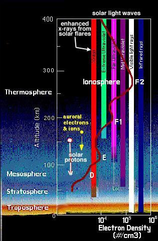
22 D-region Height: About 90 km Thickness: About 40 km Significant diurnal variations Typical daytime electron density 21
23 E-region Height: About 150 km Thickness: About 60 km Diurnal variations though not as pronounced as D-region Typical daytime electron density: 22
24 F1-region Height: About 350 km Thickness: About 200 km Diurnal variations Typical daytime electron density: 23
25 F2-region Height: About 1000 km Thickness: About 750 km Diurnal variations, though not as pronounced Electron Density: Unlike previous regions, F2 electron density decreases with height Important note: F2 becomes the F-region after sunset. 24

26 Ionospheric Properties 25
27 Electron Density: Function of Height Electron concentration per cubic centimeter (Daytime) Image from Kelley p
28 Electron Density: Function of Height Maybe doesn t seem interesting but lots going on Electron concentration per cubic centimeter (Daytime) Image from Kelley p
29 Geometric Approach 28
30 Geometric Approach Ray path in a continuously varying medium (Ionosphere) (Lied p 4) Bends away from the normal 29
31 Geometric Approach Snell s Law: 30
32 Geometric Approach Snell s Law: Index of Refraction: 31
33 Geometric Approach Snell s Law: Index of Refraction: 32
34 Geometric Approach Snell s Law: Index of Refraction: Dielectric Constant of Weakly-Ionized Gas 33
35 Geometric Approach Snell s Law: Index of Refraction: Dielectric Constant of Weakly-Ionized Gas 34
36 Geometric Approach Snell s Law: Index of Refraction: Dielectric Constant of Weakly-Ionized Gas 35
37 Geometric Approach Snell s Law: Index of Refraction: Dielectric Constant of Weakly-Ionized Gas Note dependence on electron density 36
38 Geometric Approach Within a dispersive media such as the ionosphere: 37
39 Geometric Approach Within a dispersive media such as the ionosphere: For a given frequency, as electron density increases index of refraction decreases 38
40 Geometric Approach Within a dispersive media such as the ionosphere: For a given frequency, as electron density increases index of refraction decreases For a given electron density as frequency increases index of refraction approaches unity 39
41 Index of Refraction Index of Refraction Index of Refraction as Function of Frequency E E E E E E+07 Frequency (Hz) 1.00 Index of Refraction as Function of Electron Density E E E E+11 Number of electrons per cubic meter 40
42 Geometric Approach Three Cases: 41
43 Geometric Approach Three Cases: 42
44 Geometric Approach Three Cases: 43
45 Geometric Approach Three Cases: 44
46 The Basic Absorption Equation 45
47 Basic Absorption Equation Equation for total system loss Note: Each term is a base-10 log. Hence, we add them 46
48 Basic Absorption Equation Equation for total system loss Transmitting Receiving What goes on in between Critical term is path loss Note: Each term is a base-10 log. Hence, we add them 47
49 Basic Absorption Equation Equation for path loss 48
50 Basic Absorption Equation Equation for path loss Critical term is absorption. Hence, we focus on the absorption term 49
51 Basic Absorption Equation Equation for absorption 50
52 Basic Absorption Equation Equation for absorption 51
53 Basic Absorption Equation Equation for absorption 52
54 Basic Absorption Equation Equation for absorption 53
55 Basic Absorption Equation Equation for absorption 54
56 Basic Absorption Equation 55
57 Basic Absorption Equation Kappa has units of nepers per unit length. Hence, the above equation has units of nepers 56
58 Basic Absorption Equation Kappa has units of nepers per unit length. Hence, the above equation has units of nepers From the rules of logarithms, 57
59 Basic Absorption Equation Kappa has units of nepers per unit length. Hence, the above equation has units of nepers From the rules of logarithms, 58
60 Basic Absorption Equation Kappa has units of nepers per unit length. Hence, the above equation has units of nepers From the rules of logarithms, 59
61 Basic Absorption Equation Kappa has units of nepers per unit length. Hence, the above equation has units of nepers From the rules of logarithms, Since there are roughly 8.69 db per neper the absorption equation has units of db per unit length 60
62 Types of Absorption 61
63 Types of Absorption Type of absorption depends on relationship between radio wave frequency and plasma frequency 62
64 Types of Absorption Type of absorption depends on relationship between radio wave frequency and plasma frequency Type one: Radio wave frequency about the same as plasma frequency 63
65 Types of Absorption Type of absorption depends on relationship between radio wave frequency and plasma frequency Type one: Radio wave frequency about the same as plasma frequency 64
66 Types of Absorption Type of absorption depends on relationship between radio wave frequency and plasma frequency Type one: Radio wave frequency about the same as plasma frequency Hence, the wave propagates slowly at the group velocity through ionosphere This type of absorption is called Deviative Absorption 65
67 Types of Absorption Type of absorption depends on relationship between radio wave frequency and plasma frequency Type one: Radio wave frequency about the same as plasma frequency Hence, the wave propagates slowly at the group velocity through ionosphere This type of absorption is called Deviative Absorption Deviative absorption uncommon in D-region 66
68 Types of Absorption Type of absorption depends on relationship between radio wave frequency and plasma frequency Type two: Radio wave frequency greater than plasma frequency 67
69 Types of Absorption Type of absorption depends on relationship between radio wave frequency and plasma frequency Type two: Radio wave frequency greater than plasma frequency 68
70 Types of Absorption Type of absorption depends on relationship between radio wave frequency and plasma frequency Type two: Radio wave frequency greater than plasma frequency Hence, wave propagates at about speed of light This is called non-deviative absorption Very common in D-region Note: Appendix 1 of my report presents a discussion/derivation of group and phase velocities. 69
71 Altitude (km) Types of Absorption Plasma Frequency Profile Plasma Frequency (MHz) Profile of plasma frequency from km. But we re really interested in D-region 70
72 Height (km) Types of Absorption Typical Plasma Frequency Profile within D-region Plasma Frequency (MHz) Profile of plasma frequency from km. Note plasma frequency nearly always less than 3.0 MHz 71
73 Height (km) Types of Absorption Typical Plasma Frequency Profile within D-region Plasma Frequency (MHz) Thus we see that non-deviative absorption dominates in the D-region (Assuming 3.0 < f < 30.0 MHz) 72
74 Absorption Coefficient 73
75 Absorption Coefficient In the absorption equation kappa is defined as the absorption coefficient 74
76 Absorption Coefficient In the absorption equation kappa is defined as the absorption coefficient Recall that kappa is also defined as the measure of the decay of amplitude per unit distance 75
77 Absorption Coefficient In the absorption equation kappa is defined as the absorption coefficient Recall that kappa is also defined as the measure of the decay of amplitude per unit distance I show in appendix 2 of my report that kappa is derived from Maxwell s equations Hence, the absorption equation is based on first principles 76
78 Absorption Coefficient In the absorption equation kappa is defined as the absorption coefficient Recall that kappa is also defined as the measure of the decay of amplitude per unit distance I show in appendix 2 of my report that kappa is derived from Maxwell s equations Hence, the absorption equation is based on first principles In chapter 2 of Ionospheric Radio Propagation Davies spends many pages discussing the theory of wave propagation. Starting with Maxwell s equations it can be shown that the absorption coefficient can be described by, 77
79 Absorption Coefficient In the absorption equation kappa is defined as the absorption coefficient Recall that kappa is also defined as the measure of the decay of amplitude per unit distance I show in appendix 2 of my report that kappa is derived from Maxwell s equations Hence, the absorption equation is based on first principles In chapter 2 of Ionospheric Radio Propagation Davies spends many pages discussing the theory of wave propagation. Starting with Maxwell s equations it can be shown that the absorption coefficient can be described by, 78
80 Absorption Coefficient 79
81 Absorption Coefficient Units of kappa are nepers per unit length Defining Terms: New important term! 80
82 Absorption Coefficient Units of kappa are nepers per unit length Plugging in constant values we find that, 81
83 Absorption Equation Revisited 82
84 Absorption Equation 83
85 Absorption Equation 84
86 Absorption Equation 85
87 Absorption Equation In this form integral is over path length 86
88 Absorption Equation In this form integral is over path length Electron density and collision frequency can be functions of height 87
89 Absorption Equation In this form integral is over path length Electron density and collision frequency can be functions of height 88
90 Absorption Equation 89
91 Absorption Equation 90
92 Absorption Equation Now integrated over height 91
93 Absorption Equation For special case of vertical transmission: 92
94 Absorption Equation For special case of vertical transmission: 93
95 Special Cases 94
96 Special Cases Case 1: Radio wave frequency greater than collision frequency. 95
97 Special Cases Case 1: Radio wave frequency greater than collision frequency. Case 2: Radio wave frequency less than collision frequency. 96
98 Special Cases Case 1: Radio wave frequency greater than collision frequency. Case 2: Radio wave frequency less than collision frequency. Case 3: Radio wave frequency about equal to collision frequency. 97
99 Special Cases Case 1: Radio wave frequency greater than collision frequency. Case 2: Radio wave frequency less than collision frequency. Case 3: Radio wave frequency about equal to collision frequency. According to Davies and Lied Case 1 applies generally for HF radio waves at mid-latitudes 98
100 Special Cases Case 1: Radio wave frequency greater than collision frequency. Case 2: Radio wave frequency less than collision frequency. Case 3: Radio wave frequency about equal to collision frequency. According to Davies and Lied Case 1 applies generally for HF radio waves at mid-latitudes 99
101 Special Cases Case 1: Radio wave frequency greater than collision frequency. Case 2: Radio wave frequency less than collision frequency. Case 3: Radio wave frequency about equal to collision frequency. According to Davies and Lied Case 1 applies generally for HF radio waves at mid-latitudes The absorption equation in terms of radio wave frequency in cycles per second. 100
102 Total Absorption (db) Absorption Equation Total Absorption by Frequency Frequency (MHz) Thus we see the frequency-dependence of absorption Based on data from Bain and Harrison as well as Kelley and also a HW assignment from L. Scherliess 101
103 Absorption (db0 Absorption (db) Absorption (db) Absorption (db) Absorption at 3.0 MHz Absorption at 6.0 MHz D E F Total 0 D E F Total Region Region Absorption at 15.0 MHz Absorption at 30.0 MHz D E F Total Region D E F Total Region Thus we see that most absorption takes place within the D-region Based on data from Bain and Harrison as well as Kelley and also a HW assignment from L. Scherliess 102
104 Absorption (db0 Absorption (db) Absorption (db) Absorption (db) Absorption at 3.0 MHz Absorption at 6.0 MHz D E F Total 0 D E F Total Region Region Absorption at 15.0 MHz Absorption at 30.0 MHz D E F Total Region D E F Total Region Thus we see that most absorption takes place within the D-region Based on data from Bain and Harrison as well as Kelley and also a HW assignment from L. Scherliess 103
105 Electron Density 104
106 Electron Density Typical electron concentration per cubic centimeter (Daytime) Image from Kelley p
107 Electron Density Again, not too interesting Typical electron concentration per cubic centimeter (Daytime) Image from Kelley p
108 Altitude (km) Electron Density Electron Density Profile E E E E E E E+12 Electron Density (per cubic meter) Based on Bain and Harrison [1972] Electron density profile below 100 km 107
109 Electron Density Everything depends on electron density 108
110 Electron Density Everything depends on electron density Plasma Frequency 109
111 Electron Density Everything depends on electron density Plasma Frequency Index of Refraction 110
112 Electron Density Everything depends on electron density Plasma Frequency Index of Refraction Absorption Coefficient 111
113 Electron Density Everything depends on electron density Plasma Frequency Index of Refraction Absorption Coefficient Thus we see that electron density is the most critical component 112
114 Collision Frequency 113
115 Collision Frequency We are concerned with two collision types: Electron- ion Electron-neutral 114
116 Collision Frequency We are concerned with two collision types: Electron- ion Electron-neutral We find the following equations for collision frequencies: 115
117 Collision Frequency We are concerned with two collision types: Electron- ion Electron-neutral We find the following equations for collision frequencies: 116
118 Collision Frequency We are concerned with two collision types: Electron- ion Electron-neutral We find the following equations for collision frequencies: Electron-Ion: 117
119 Collision Frequency We are concerned with two collision types: Electron- ion Electron-neutral We find the following equations for collision frequencies: Electron-Ion: Electron-Neutral: 118
120 Collision Frequency We are concerned with two collision types: Electron- ion Electron-neutral We find the following equations for collision frequencies: Electron-Ion: Electron-Neutral: 119
121 Collision Frequency We are able to make the following simplifying assumptions: 120
122 Collision Frequency We are able to make the following simplifying assumptions: Within the D-region, the neutral atmosphere density is fairly consistent 121
123 Collision Frequency We are able to make the following simplifying assumptions: Within the D-region, the neutral atmosphere density is fairly consistent Within the D-region,. Hence we need only consider electron-neutral collisions 122
124 Collision Frequency We are able to make the following simplifying assumptions: Within the D-region, the neutral atmosphere density is fairly consistent Within the D-region, Within the D-region. Hence we need only consider electron-neutral collisions. Hence it is sufficient to us the neutral temperature 123
125 Collision Frequency We are able to make the following simplifying assumptions: Within the D-region, the neutral atmosphere density is fairly consistent Within the D-region, Within the D-region. Hence we need only consider electron-neutral collisions. Hence it is sufficient to us the neutral temperature 124
126 Collision Frequency We are able to make the following simplifying assumptions: Within the D-region, the neutral atmosphere density is fairly consistent Within the D-region, Within the D-region. Hence we need only consider electron-neutral collisions. Hence it is sufficient to us the neutral temperature 125
127 Conclusions/Discussion 126
128 Conclusions/Discussion We showed the following to be true: 127
129 Conclusions/Discussion We showed the following to be true: Absorption is frequency-dependent 128
130 Conclusions/Discussion We showed the following to be true: Absorption is frequency-dependent Most HF absorption takes place within the D-region 129
131 Conclusions/Discussion We showed the following to be true: Absorption is frequency-dependent Most HF absorption takes place within the D-region Within the D-region non-deviative absorption dominates 130
132 Conclusions/Discussion We showed the following to be true: Absorption is frequency-dependent Most HF absorption takes place within the D-region Within the D-region non-deviative absorption dominates The electron density is the most critical component 131
133 Conclusions/Discussion We showed the following to be true: Non-deviative absorption within the D-region can be described mathematically in terms of neutral density or collision frequency, 132
134 Conclusions/Discussion We showed the following to be true: Non-deviative absorption within the D-region can be described mathematically in terms of neutral density or collision frequency, 133
135 Acknowledgments Special thanks to the following who assisted in the preparation of the presentation Dr. Jan J. Sojka Dr. Vince Eccles And thank you to my supervisory committee: Doctors J. Sojka, D. Peak, B. Fejer, M. Taylor, R. Fullmer 134
136 Key Sources References 135
137 fin 136
138 Questions? 137
139 138
140 139
141 140
142 Frequency (MHz) D-region absorption values using data from Bain and Harrison 141
Ionospheric Propagation
 Ionospheric Propagation Page 1 Ionospheric Propagation The ionosphere exists between about 90 and 1000 km above the earth s surface. Radiation from the sun ionizes atoms and molecules here, liberating
Plasma in the ionosphere Ionization and Recombination
 Plasma in the ionosphere Ionization and Recombination Jamil Muhammad Supervisor: Professor kjell Rönnmark 1 Contents: 1. Introduction 3 1.1 History.3 1.2 What is the ionosphere?...4 2. Ionization and recombination.5
Plasma Turbulence of Non-Specular Trail Plasmas as Measured by a High Power Large Aperture Radar
 Space Environment and Satellite Systems Plasma Turbulence of Non-Specular Trail Plasmas as Measured by a High Power Large Aperture Radar Jonathan Yee and Sigrid Close Stanford University January 9, 2013
Session2 Antennas and Propagation
 Wireless Communication Presented by Dr. Mahmoud Daneshvar Session2 Antennas and Propagation 1. Introduction Types of Anttenas Free space Propagation 2. Propagation modes 3. Transmission Problems 4. Fading
High Frequency Propagation (and a little about NVIS)
") High Frequency Propagation (and a little about NVIS) Tom McDermott, N5EG August 18, 2010 September 2, 2010 Updated: February 7, 2013 The problem Radio waves, like light waves, travel in ~straight lines.
High Frequency Propagation (and a little about NVIS) Tom McDermott, N5EG August 18, 2010 September 2, 2010 Updated: February 7, 2013 The problem Radio waves, like light waves, travel in ~straight lines.
Lesson 12: Signal Propagation
 Lesson 12: Signal Propagation Preparation for Amateur Radio Technician Class Exam Topics HF Propagation Ground-wave Sky-wave Ionospheric regions VHF/UHF Propagation Line-of-sight Tropospheric Bending and
Ionospheric Propagation
 Ionospheric Nick Massey VA7NRM 1 Electromagnetic Spectrum Radio Waves are a form of Electromagnetic Radiation Visible Light is also a form of Electromagnetic Radiation Radio Waves behave a lot like light
Antennas & Propagation. CSG 250 Fall 2007 Rajmohan Rajaraman
 Antennas & Propagation CSG 250 Fall 2007 Rajmohan Rajaraman Introduction An antenna is an electrical conductor or system of conductors o Transmission - radiates electromagnetic energy into space o Reception
Maximum Usable Frequency
 Maximum Usable Frequency 15 Frequency (MHz) 10 5 0 Maximum Usable Frequency Usable Frequency Window Lowest Usable Frequency Solar Flare 6 12 18 24 Time (Hours) Radio Blackout Usable Frequency Window Ken
Chapter 7 HF Propagation. Ionosphere Solar Effects Scatter and NVIS
 Chapter 7 HF Propagation Ionosphere Solar Effects Scatter and NVIS Ionosphere and Layers Radio Waves Bent by the Ionosphere Daily variation of Ionosphere Layers Ionospheric Reflection Conduction by electrons
Introduction To The Ionosphere
 Introduction To The Ionosphere John Bosco Habarulema Radar School 12 13 September 2015, SANSA, What is a radar? This being a radar school... RAdio Detection And Ranging To determine the range, R, R=Ct/2,
Chapter 15: Radio-Wave Propagation
 Chapter 15: Radio-Wave Propagation MULTIPLE CHOICE 1. Radio waves were first predicted mathematically by: a. Armstrong c. Maxwell b. Hertz d. Marconi 2. Radio waves were first demonstrated experimentally
Polarization orientation of the electric field vector with respect to the earth s surface (ground).
.") Free space propagation of electromagnetic waves is often called radio-frequency (rf) propagation or simply radio propagation. The earth s atmosphere, as medium introduces losses and impairments to the
Free space propagation of electromagnetic waves is often called radio-frequency (rf) propagation or simply radio propagation. The earth s atmosphere, as medium introduces losses and impairments to the
Reading 28 PROPAGATION THE IONOSPHERE
 Reading 28 Ron Bertrand VK2DQ http://www.radioelectronicschool.com PROPAGATION THE IONOSPHERE The ionosphere is a region of the upper atmosphere extending from a height of about 60 km to greater than 500
Antennas and Propagation
 Mobile Networks Module D-1 Antennas and Propagation 1. Introduction 2. Propagation modes 3. Line-of-sight transmission 4. Fading Slides adapted from Stallings, Wireless Communications & Networks, Second
RADIOWAVE PROPAGATION
 RADIOWAVE PROPAGATION Physics and Applications CURT A. LEVIS JOEL T. JOHNSON FERNANDO L. TEIXEIRA The cover illustration is part of a figure from R.C. Kirby, "Introduction," Lecture 1 in NBS Course in
Antennas and Propagation. Chapter 5
 Antennas and Propagation Chapter 5 Introduction An antenna is an electrical conductor or system of conductors Transmission - radiates electromagnetic energy into space Reception - collects electromagnetic
Antennas and Propagation
 Antennas and Propagation Chapter 5 Introduction An antenna is an electrical conductor or system of conductors Transmission - radiates electromagnetic energy into space Reception - collects electromagnetic
Radio Propagation Fundamentals
 Radio Propagation Fundamentals Concept of Electromagnetic Wave Propagation Mechanisms Modes of Propagation Propagation Models Path Profiles Link Budget Fading Channels Electromagnetic (EM) Waves EM Wave
ATMOSPHERIC NUCLEAR EFFECTS
 EC3630 Radiowave Propagation ATMOSPHERIC NUCLEAR EFFECTS by Professor David Jenn (version 1.1) 1 Atmospheric Nuclear Effects (1) The effect of a nuclear blast on the atmosphere is a complicated function
Chapter 1: Telecommunication Fundamentals
 Chapter 1: Telecommunication Fundamentals Block Diagram of a communication system Noise n(t) m(t) Information (base-band signal) Signal Processing Carrier Circuits s(t) Transmission Medium r(t) Signal
Estimation of Pulse Repetition Frequency for Ionospheric Communication
 International Journal of Electronics and Communication Engineering. ISSN 0974-266 Volume 4, Number 3 (20), pp. 25-258 International Research Publication House http:www.irphouse.com Estimation of Pulse
Antennas and Propagation. Chapter 5
 Antennas and Propagation Chapter 5 Introduction An antenna is an electrical conductor or system of conductors Transmission - radiates electromagnetic energy into space Reception - collects electromagnetic
Channel Modeling and Characteristics
 Channel Modeling and Characteristics Dr. Farid Farahmand Updated:10/15/13, 10/20/14 Line-of-Sight Transmission (LOS) Impairments The received signal is different from the transmitted signal due to transmission
THE IONOSPHERE AND RADIO PROPAGATION
 INTERNATIONAL JOURNAL OF ELECTRONICS AND COMMUNICATION ENGINEERING & TECHNOLOGY (IJECET) International Journal of Electronics and Communication Engineering & Technology (IJECET), ISSN 0976 ISSN 0976 6464(Print)
Penetration of VLF Radio Waves through the Ionosphere
 Penetration of VLF Radio Waves through the Ionosphere By Ken-ichi MAEDA and Hiroshi OYA Kyoto University, Kyoto, Japan (Read May 24; Received November 25, 1962) Abstract The rate of energy penetration
Data and Computer Communications. Tenth Edition by William Stallings
 Data and Computer Communications Tenth Edition by William Stallings Data and Computer Communications, Tenth Edition by William Stallings, (c) Pearson Education - Prentice Hall, 2013 Wireless Transmission
RECOMMENDATION ITU-R P HF PROPAGATION PREDICTION METHOD* (Question ITU-R 223/3)
") Rec. ITU-R P.533-6 1 RECOMMENDATION ITU-R P.533-6 HF PROPAGATION PREDICTION METHOD* (Question ITU-R 223/3) Rec. ITU-R P.533-6 (1978-1982-1990-1992-1994-1995-1999) The ITU Radiocommunication Assembly, considering
Rec. ITU-R P.533-6 1 RECOMMENDATION ITU-R P.533-6 HF PROPAGATION PREDICTION METHOD* (Question ITU-R 223/3) Rec. ITU-R P.533-6 (1978-1982-1990-1992-1994-1995-1999) The ITU Radiocommunication Assembly, considering
EEM.Ant. Antennas and Propagation
 EEM.ant/0304/08pg/Req: None 1/8 UNIVERSITY OF SURREY Department of Electronic Engineering MSc EXAMINATION EEM.Ant Antennas and Propagation Duration: 2 Hours Spring 2003/04 READ THESE INSTRUCTIONS Answer
If maximum electron density in a layer is less than n', the wave will penetrate the layer
 UNIT-7 1. Briefly the describe the terms related to the sky wave propagation: virtual heights, critical frequency, maximum usable frequency, skip distance and fading? Ans: Sky wave propagation: It is also
3 Methods of radiocommunication
 + + & & * * ) ) From the ITU Emergency Telecommunications handbook; prepared for the 54 th JOTA 2011. 3 Methods of radiocommunication 3.1 Frequencies Radio frequencies should be selected according to propagation
Sw earth Dw Direct wave GRw Ground reflected wave Sw Surface wave
 WAVE PROPAGATION By Marcel H. De Canck, ON5AU Electromagnetic radio waves can propagate in three different ways between the transmitter and the receiver. 1- Ground waves 2- Troposphere waves 3- Sky waves
The USU-GAIM Data Assimilation Models for Ionospheric Specifications and Forecasts
 The USU-GAIM Data Assimilation Models for Ionospheric Specifications and Forecasts L. Scherliess, R. W. Schunk, L. C. Gardner, L. Zhu, J.V. Eccles and J.J Sojka Center for Atmospheric and Space Sciences
OBJECTIVES: PROPAGATION INTRO RADIO WAVES POLARIZATION LINE OF SIGHT, GROUND WAVE, SKY WAVE IONOSPHERE REGIONS PROPAGATION, HOPS, SKIPS ZONES THE
 WAVE PROPAGATION OBJECTIVES: PROPAGATION INTRO RADIO WAVES POLARIZATION LINE OF SIGHT, GROUND WAVE, SKY WAVE IONOSPHERE REGIONS PROPAGATION, HOPS, SKIPS ZONES THE IONOSPHERIC LAYERS ABSORPTION AND FADING
Ionospheric Absorption
 Ionospheric Absorption Prepared by Forrest Foust Stanford University, Stanford, CA IHY Workshop on Advancing VLF through the Global AWESOME Network VLF Injection Into the Magnetosphere Earth-based VLF
Storms in Earth s ionosphere
 Storms in Earth s ionosphere Archana Bhattacharyya Indian Institute of Geomagnetism IISF 2017, WSE Conclave; Anna University, Chennai Earth s Ionosphere Ionosphere is the region of the atmosphere in which
Comparing the Low-- and Mid Latitude Ionosphere and Electrodynamics of TIE-GCM and the Coupled GIP TIE-GCM
 Comparing the Low-- and Mid Latitude Ionosphere and Electrodynamics of TIE-GCM and the Coupled GIP TIE-GCM Clarah Lelei Bryn Mawr College Mentors: Dr. Astrid Maute, Dr. Art Richmond and Dr. George Millward
Space Weather and Propagation JANUARY 14, 2017
 Space Weather and Propagation MARTIN BUEHRING -KB4MG ELEC T R ICAL ENGINEER, A M AT EUR EXTRA CLASS LICENSE HOLDER JANUARY 14, 2017 Why know about Space Weather? Our SUN has an enormous affect not only
RECOMMENDATION ITU-R P HF propagation prediction method *
 Rec. ITU-R P.533-7 1 RECOMMENDATION ITU-R P.533-7 HF propagation prediction method * (Question ITU-R 3/3) (1978-198-1990-199-1994-1995-1999-001) The ITU Radiocommunication Assembly, considering a) that
Effects of magnetic storms on GPS signals
 Effects of magnetic storms on GPS signals Andreja Sušnik Supervisor: doc.dr. Biagio Forte Outline 1. Background - GPS system - Ionosphere 2. Ionospheric Scintillations 3. Experimental data 4. Conclusions
RECOMMENDATION ITU-R P Prediction of sky-wave field strength at frequencies between about 150 and khz
 Rec. ITU-R P.1147-2 1 RECOMMENDATION ITU-R P.1147-2 Prediction of sky-wave field strength at frequencies between about 150 and 1 700 khz (Question ITU-R 225/3) (1995-1999-2003) The ITU Radiocommunication
14. COMMUNICATION SYSTEM
 14. COMMUNICATION SYSTEM SYNOPSIS : INTRODUCTION 1. The exchange of information between a sender and receiver is called communication. 2. The arrangement of devices to transfere the information is called
MUF: Spokane to Cleveland October, 2100 UTC
 MHz What Mode of Propagation Enables JT65/JT9/FT8? Carl Luetzelschwab K9LA August 2017 Revision 1 (thanks W4TV) The purpose of this article is not to rigorously analyze how much improvement each JT mode
Antennas and Propagation
 CMPE 477 Wireless and Mobile Networks Lecture 3: Antennas and Propagation Antennas Propagation Modes Line of Sight Transmission Fading in the Mobile Environment Introduction An antenna is an electrical
Data and Computer Communications Chapter 4 Transmission Media
 Data and Computer Communications Chapter 4 Transmission Media Ninth Edition by William Stallings Data and Computer Communications, Ninth Edition by William Stallings, (c) Pearson Education - Prentice Hall,
UNDER STANDING RADIO FREQUENCY Badger Meter, Inc.
 UNDER STANDING RADIO FREQUENCY UNDERSTANDING RADIO FREQUENCY Regional Sales Meeting March 1-2, 2011 Brian Fiut Sr. Product Manager Itron Inc. Liberty Lake, WA August 25, 2010 RADIO PROPAGATION Radio consists
Monitoring Solar flares by Radio Astronomy
 Monitoring Solar flares by Radio Astronomy Presented at the RASC Sunshine Coast Centre, February 8th, 2013, 7:30 pm Mike Bradley, RASC Sunshine Coast Centre Solar flares Solar flares occur when sunspots
Ionospheric Impacts on UHF Space Surveillance. James C. Jones Darvy Ceron-Gomez Dr. Gregory P. Richards Northrop Grumman
 Ionospheric Impacts on UHF Space Surveillance James C. Jones Darvy Ceron-Gomez Dr. Gregory P. Richards Northrop Grumman CONFERENCE PAPER Earth s atmosphere contains regions of ionized plasma caused by
Groundwave Propagation, Part One
 Groundwave Propagation, Part One 1 Planar Earth groundwave 2 Planar Earth groundwave example 3 Planar Earth elevated antenna effects Levis, Johnson, Teixeira (ESL/OSU) Radiowave Propagation August 17,
Propagation Modelling White Paper
 Propagation Modelling White Paper Propagation Modelling White Paper Abstract: One of the key determinants of a radio link s received signal strength, whether wanted or interfering, is how the radio waves
REFLECTION AND TRANSMISSION IN THE IONOSPHERE CONSIDERING COLLISIONS IN A FIRST APPROXIMATION
 Progress In Electromagnetics Research Letters, Vol. 1, 93 99, 2008 REFLECTION AND TRANSMISSION IN THE IONOSPHERE CONSIDERING COLLISIONS IN A FIRST APPROXIMATION A. Yesil and M. Aydoğdu Department of Physics
The Significance of GNSS for Radio Science
 Space Weather Effects on the Wide Area Augmentation System (WAAS) The Significance of GNSS for Radio Science Patricia H. Doherty Vice Chair, Commission G International Union of Radio Science www.ursi.org
Using the Radio Spectrum to Understand Space Weather
 Using the Radio Spectrum to Understand Space Weather Ray Greenwald Virginia Tech Topics to be Covered What is Space Weather? Origins and impacts Analogies with terrestrial weather Monitoring Space Weather
ESS 7 Lectures 15 and 16 November 3 and 5, The Atmosphere and Ionosphere
 ESS 7 Lectures 15 and 16 November 3 and 5, 2008 The Atmosphere and Ionosphere The Earth s Atmosphere The Earth s upper atmosphere is important for groundbased and satellite radio communication and navigation.
CRITICAL FREQUENCY By Marcel H. De Canck, ON5AU
 CRITICAL FREQUENCY By Marcel H. De Canck, ON5AU Before reading onward, it would be good to refresh your knowledge about refraction rules in the section on Refraction of the earlier "Wave Propagation Direction
Atmospheric Effects. Atmospheric Refraction. Atmospheric Effects Page 1
 Atmospheric Effects Page Atmospheric Effects The earth s atmosphere has characteristics that affect the propagation of radio waves. These effects happen at different points in the atmosphere, and hence
right during the VE Session Have fun Bob, KA9BH Eric, K9VIC
 Radio Wave Propagation Teach you enough to get all right during the VE Session Learn a few things from you Have fun Finish everything on time (if the propagation questions about your experiences not a
Chapter 1 Introduction
 Wireless Information Transmission System Lab. Chapter 1 Introduction National Sun Yat-sen University Table of Contents Elements of a Digital Communication System Communication Channels and Their Wire-line
Broad Principles of Propagation 4C4
 Broad Principles of Propagation ledoyle@tcd.ie 4C4 Starting at the start All wireless systems use spectrum, radiowaves, electromagnetic waves to function It is the fundamental and basic ingredient of
Dependence of radio wave anomalous attenuation in the ionosphere on properties of spatial spectrum of irregularities
 Dependence of radio wave anomalous attenuation in the ionosphere on properties of spatial spectrum of irregularities N.A. Zabotin, G.A. Zhbankov and E.S. Kovalenko ostov State University, ostov-on-don,
Antenna & Propagation. Basic Radio Wave Propagation
 For updated version, please click on http://ocw.ump.edu.my Antenna & Propagation Basic Radio Wave Propagation by Nor Hadzfizah Binti Mohd Radi Faculty of Electric & Electronics Engineering hadzfizah@ump.edu.my
The Earth s Atmosphere
 ESS 7 Lectures 15 and 16 May 5 and 7, 2010 The Atmosphere and Ionosphere The Earth s Atmosphere The Earth s upper atmosphere is important for groundbased and satellite radio communication and navigation.
1. Terrestrial propagation
 Rec. ITU-R P.844-1 1 RECOMMENDATION ITU-R P.844-1 * IONOSPHERIC FACTORS AFFECTING FREQUENCY SHARING IN THE VHF AND UHF BANDS (30 MHz-3 GHz) (Question ITU-R 218/3) (1992-1994) Rec. ITU-R PI.844-1 The ITU
RECOMMENDATION ITU-R F.1404*
 Rec. ITU-R F.1404 1 RECOMMENDATION ITU-R F.1404* Rec. ITU-R F.1404 MINIMUM PROPAGATION ATTENUATION DUE TO ATMOSPHERIC GASES FOR USE IN FREQUENCY SHARING STUDIES BETWEEN SYSTEMS IN THE FIXED SERVICE AND
EITN85, FREDRIK TUFVESSON, JOHAN KÅREDAL ELECTRICAL AND INFORMATION TECHNOLOGY. Why do we need UWB channel models?
 Wireless Communication Channels Lecture 9:UWB Channel Modeling EITN85, FREDRIK TUFVESSON, JOHAN KÅREDAL ELECTRICAL AND INFORMATION TECHNOLOGY Overview What is Ultra-Wideband (UWB)? Why do we need UWB channel
Currents, Electrojets and Instabilities. John D Sahr Electrical Engineering University of Washington 19 June 2016
 Currents, Electrojets and Instabilities John D Sahr Electrical Engineering University of Washington 19 June 2016 Outline The two main sources of large scale currents in the ionosphere: solar-wind/magnetosphere,
UNIT Derive the fundamental equation for free space propagation?
 UNIT 8 1. Derive the fundamental equation for free space propagation? Fundamental Equation for Free Space Propagation Consider the transmitter power (P t ) radiated uniformly in all the directions (isotropic),
Ionospheric effect of HF surface wave over-the-horizon radar
 RADIO SCIENCE, VOL. 41,, doi:10.1029/2005rs003323, 2006 Ionospheric effect of HF surface wave over-the-horizon radar Huotao Gao, 1 Geyang Li, 1 Yongxu Li, 1 Zijie Yang, 1 and Xiongbin Wu 1 Received 25
EFFECT OF IONOSPHERIC INDUCED DEPOLARIZA- TION ON SATELLITE SOLAR POWER STATION
 Progress In Electromagnetics Research Letters, Vol. 9, 39 47, 29 EFFECT OF IONOSPHERIC INDUCED DEPOLARIZA- TION ON SATELLITE SOLAR POWER STATION K. Chaudhary and B. R. Vishvakarma Electronics Engineering
Measurement of VLF propagation perturbations during the January 4, 2011 Partial Solar Eclipse
 Measurement of VLF propagation perturbations during the January 4, 2011 Partial Solar Eclipse by Lionel Loudet 1 January 2011 Contents Abstract...1 Introduction...1 Background...2 VLF Signal Propagation...2
Daytime modelling of VLF radio waves over land and sea, comparison with data from DEMETER Satellite
 Daytime modelling of VLF radio waves over land and sea, comparison with data from DEMETER Satellite S. G. Meyer 1,2, A. B. Collier 1,2, C. J. Rodger 3 1 SANSA Space Science, Hermanus, South Africa 2 School
INSTITUTE OF AERONAUTICAL ENGINEERING Dundigal, Hyderabad ELECTRONICS AND COMMUNIACTION ENGINEERING QUESTION BANK
 INSTITUTE OF AERONAUTICAL ENGINEERING Dundigal, Hyderabad - 500 04 ELECTRONICS AND COMMUNIACTION ENGINEERING QUESTION BANK Course Name : Antennas and Wave Propagation (AWP) Course Code : A50418 Class :
Terrestrial Ionospheres
 Terrestrial Ionospheres I" Stan Solomon" High Altitude Observatory National Center for Atmospheric Research Boulder, Colorado stans@ucar.edu Heliophysics Summer School National Center for Atmospheric Research
Ducting and Spotlight Propagation on 160m Carl Luetzelschwab K9LA
 Ducting and Spotlight Propagation on 160m Carl Luetzelschwab K9LA [this article appeared in the December 2005 issue of CQ] If you enjoyed reading about the issues that contribute to the unpredictability
Unguided Media and Matched Filter After this lecture, you will be able to Example?
 Unguided Media and Matched Filter After this lecture, you will be able to describe the physical and transmission characteristics of various unguided media Example? B.1 Unguided media Guided to unguided
Study of small scale plasma irregularities. Đorđe Stevanović
 Study of small scale plasma irregularities in the ionosphere Đorđe Stevanović Overview 1. Global Navigation Satellite Systems 2. Space weather 3. Ionosphere and its effects 4. Case study a. Instruments
Electron acceleration and ionization fronts induced by high frequency plasma turbulence
 Eliasson, Bengt (2014) Electron acceleration and ionization fronts induced by high frequency plasma turbulence. In: 41st IOP Plasma Physics Conference, 2014-04-14-2014-04-17, Grand Connaught Rooms., This
Get Discount Coupons for your Coaching institute and FREE Study Material at COMMUNICATION SYSTEMS
 COMMUNICATION SYSTEMS 1. BASICS OF COMMUNICATION 2. AMPLITUDE MODULATION Get Discount Coupons for your Coaching institute and FREE Study Material at www.pickmycoaching.com 1 BASICS OF COMMUNICATION 1.
h max 20 TX Ionosphere d 1649 km Radio and Optical Wave Propagation Prof. L. Luini, July 1 st, 2016 SURNAME AND NAME ID NUMBER SIGNATURE
 Radio and Optical Wave Propagation Prof. L. Luini, July st, 06 3 4 do not write above SURNAME AND NAME ID NUMBER SIGNATURE Exercise Making reference to the figure below, the transmitter TX, working at
Technician License Course Chapter 4
 Technician License Course Chapter 4 Propagation, Basic Antennas, Feed lines & SWR K0NK 26 Jan 18 The Antenna System Antenna: Facilitates the sending of your signal to some distant station. Feed line: Connects
Satellite Signals and Communications Principles. Dr. Ugur GUVEN Aerospace Engineer (P.hD)
") Satellite Signals and Communications Principles Dr. Ugur GUVEN Aerospace Engineer (P.hD) Principle of Satellite Signals In essence, satellite signals are electromagnetic waves that travel from the satellite
Satellite Signals and Communications Principles Dr. Ugur GUVEN Aerospace Engineer (P.hD) Principle of Satellite Signals In essence, satellite signals are electromagnetic waves that travel from the satellite
The Global Atmospheric Electric Circuit
 The Global Atmospheric Electric Circuit Colin Price Department of Geophysics and Planetary Sciences Tel Aviv University Israel cprice@flash.tau.ac.il Historical Background 1752 Lemonnier discovered that
Investigation of electron density profile in the lower ionosphere by SRP-4 rocket experiment
 Earth Planets Space, 57, 879 884, 25 Investigation of electron density profile in the lower ionosphere by SRP-4 rocket experiment K. Ishisaka 1, T. Okada 1, J. Hawkins 2, S. Murakami 1, T. Miyake 1, Y.
Scientific Studies of the High-Latitude Ionosphere with the Ionosphere Dynamics and ElectroDynamics - Data Assimilation (IDED-DA) Model
 Model") DISTRIBUTION STATEMENT A. Approved for public release; distribution is unlimited. Scientific Studies of the High-Latitude Ionosphere with the Ionosphere Dynamics and ElectroDynamics - Data Assimilation
DISTRIBUTION STATEMENT A. Approved for public release; distribution is unlimited. Scientific Studies of the High-Latitude Ionosphere with the Ionosphere Dynamics and ElectroDynamics - Data Assimilation
Electromagnetic (Light) Waves Electromagnetic Waves
 Waves Electromagnetic Waves") Physics R Date: Review Questions 1. An ocean wave traveling at 3 m/s has a wavelength of 1.6 meters. a. What is the frequency of the wave? b. What is the period of the wave? Electromagnetic (Light) Waves
Physics R Date: Review Questions 1. An ocean wave traveling at 3 m/s has a wavelength of 1.6 meters. a. What is the frequency of the wave? b. What is the period of the wave? Electromagnetic (Light) Waves
Antennas and Propagation. Prelude to Chapter 4 Propagation
 Antennas and Propagation Prelude to Chapter 4 Propagation Introduction An antenna is an electrical conductor or system of conductors for: Transmission - radiates electromagnetic energy into space (involves
Modification of Earth-Space Rain Attenuation Model for Earth- Space Link
 IOSR Journal of Electronics and Communication Engineering (IOSR-JECE) e-issn: 2278-2834,p- ISSN: 2278-8735.Volume 9, Issue 2, Ver. VI (Mar - Apr. 2014), PP 63-67 Modification of Earth-Space Rain Attenuation
Use of GNSS Radio Occultation data for Climate Applications Bill Schreiner Sergey Sokolovskiy, Doug Hunt, Ben Ho, Bill Kuo UCAR
 Use of GNSS Radio Occultation data for Climate Applications Bill Schreiner (schrein@ucar.edu), Sergey Sokolovskiy, Doug Hunt, Ben Ho, Bill Kuo UCAR COSMIC Program Office www.cosmic.ucar.edu 1 Questions
Microwave and optical systems Introduction p. 1 Characteristics of waves p. 1 The electromagnetic spectrum p. 3 History and uses of microwaves and
 Microwave and optical systems Introduction p. 1 Characteristics of waves p. 1 The electromagnetic spectrum p. 3 History and uses of microwaves and optics p. 4 Communication systems p. 6 Radar systems p.
# DEFINITIONS TERMS. 2) Electrical energy that has escaped into free space. Electromagnetic wave
 Electrical energy that has escaped into free space. Electromagnetic wave") CHAPTER 14 ELECTROMAGNETIC WAVE PROPAGATION # DEFINITIONS TERMS 1) Propagation of electromagnetic waves often called radio-frequency (RF) propagation or simply radio propagation. Free-space 2) Electrical
CHAPTER 14 ELECTROMAGNETIC WAVE PROPAGATION # DEFINITIONS TERMS 1) Propagation of electromagnetic waves often called radio-frequency (RF) propagation or simply radio propagation. Free-space 2) Electrical
The spatial structure of an acoustic wave propagating through a layer with high sound speed gradient
 The spatial structure of an acoustic wave propagating through a layer with high sound speed gradient Alex ZINOVIEV 1 ; David W. BARTEL 2 1,2 Defence Science and Technology Organisation, Australia ABSTRACT
UWB Channel Modeling
 Channel Modeling ETIN10 Lecture no: 9 UWB Channel Modeling Fredrik Tufvesson & Johan Kåredal, Department of Electrical and Information Technology fredrik.tufvesson@eit.lth.se 2011-02-21 Fredrik Tufvesson
Akio Oniyama 1 and Tetsuo Fukunaga 2 PASCO CORPORATION Nakano, Nakano-ku, Tokyo, Japan
 SpaceOps Conferences 16-20 May 2016, Daejeon, Korea SpaceOps 2016 Conference 10.2514/6.2016-2434 A Case Study of the Data Downlink Methodology for Earth Observation Satellite Akio Oniyama 1 and Tetsuo
AGF-216. The Earth s Ionosphere & Radars on Svalbard
 AGF-216 The Earth s Ionosphere & Radars on Svalbard Katie Herlingshaw 07/02/2018 1 Overview Radar basics what, how, where, why? How do we use radars on Svalbard? What is EISCAT and what does it measure?
Plasma in the Ionosphere Ionization and Recombination
 Plasma in the Ionosphere Ionization and Recombination Agabi E Oshiorenoya July, 2004 Space Physics 5P Umeå Universitet Department of Physics Umeå, Sweden Contents 1 Introduction 6 2 Ionization and Recombination
Ground Penetrating Radar
 Ground Penetrating Radar Begin a new section: Electromagnetics First EM survey: GPR (Ground Penetrating Radar) Physical Property: Dielectric constant Electrical Permittivity EOSC 350 06 Slide Di-electric
Chapter 13: Wave Propagation. EET-223: RF Communication Circuits Walter Lara
 Chapter 13: Wave Propagation EET-223: RF Communication Circuits Walter Lara Electrical to Electromagnetic Conversion Since the atmosphere is not a conductor of electrons (instead a good insulator), electrical
Channel Modeling ETI 085
 Channel Modeling ETI 085 Overview Lecture no: 9 What is Ultra-Wideband (UWB)? Why do we need UWB channel models? UWB Channel Modeling UWB channel modeling Standardized UWB channel models Fredrik Tufvesson
Examination of Three Empirical Atmospheric Models
 Examination of Three Empirical Atmospheric Models A Presentation Given to The Department of Physics Utah State University In Partial Fulfillment of the Requirements for the Degree Doctor of Philosophy
Wave Propagation and Antenna Engineering
 Wave Propagation and Antenna Engineering Wave Propagation and Antenna Engineering SANJAY KUMAR Air Commodore (Retd.) Former AOC, 9 BRD, IAF Pune and Former Principal Adviser Defence Avionics Research