Model FL8300 SERVICE MANUAL. harman/kardon. 5 Disc Compact Disc Changer CONTENTS
|
|
|
- Geraldine Page
- 5 years ago
- Views:
Transcription

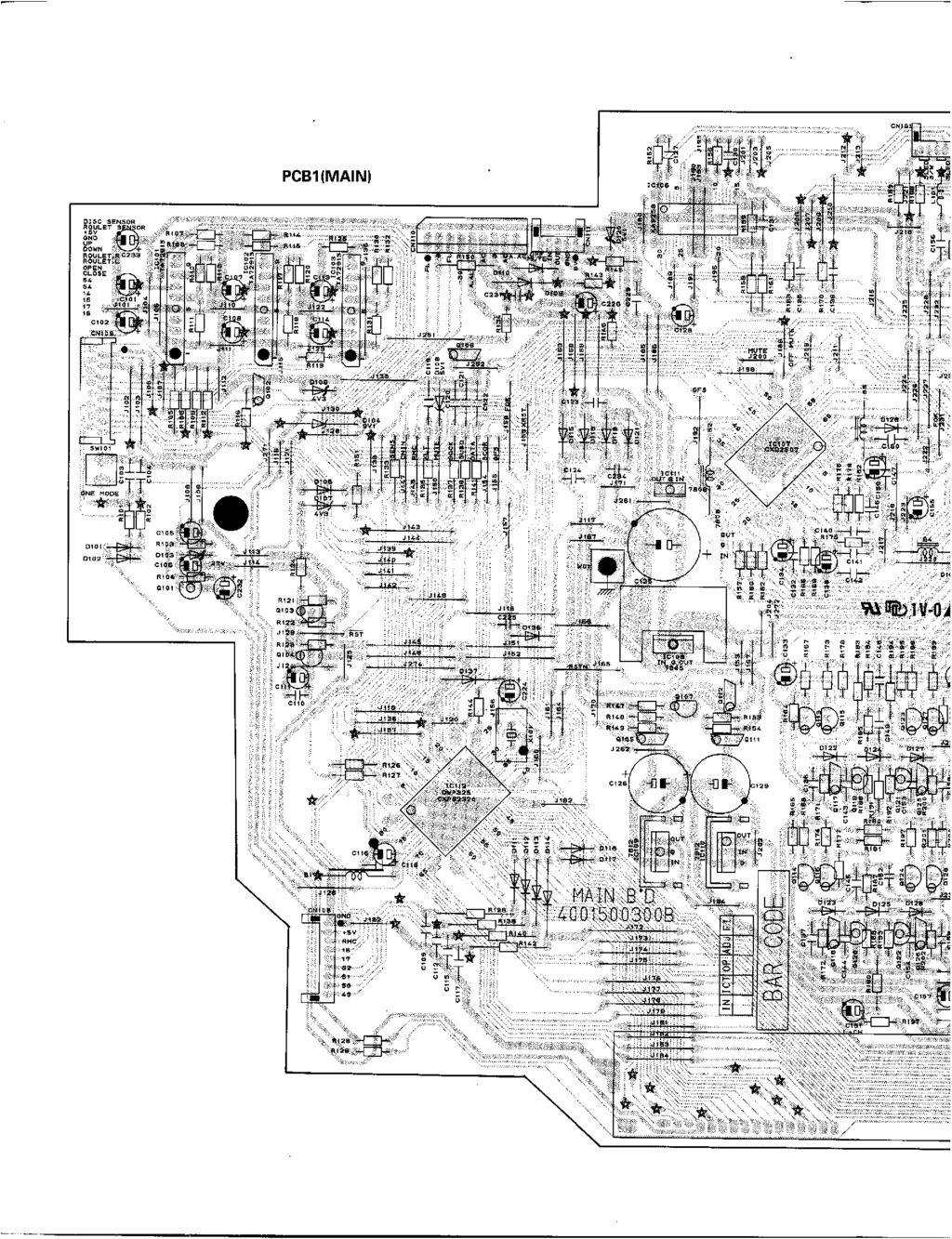
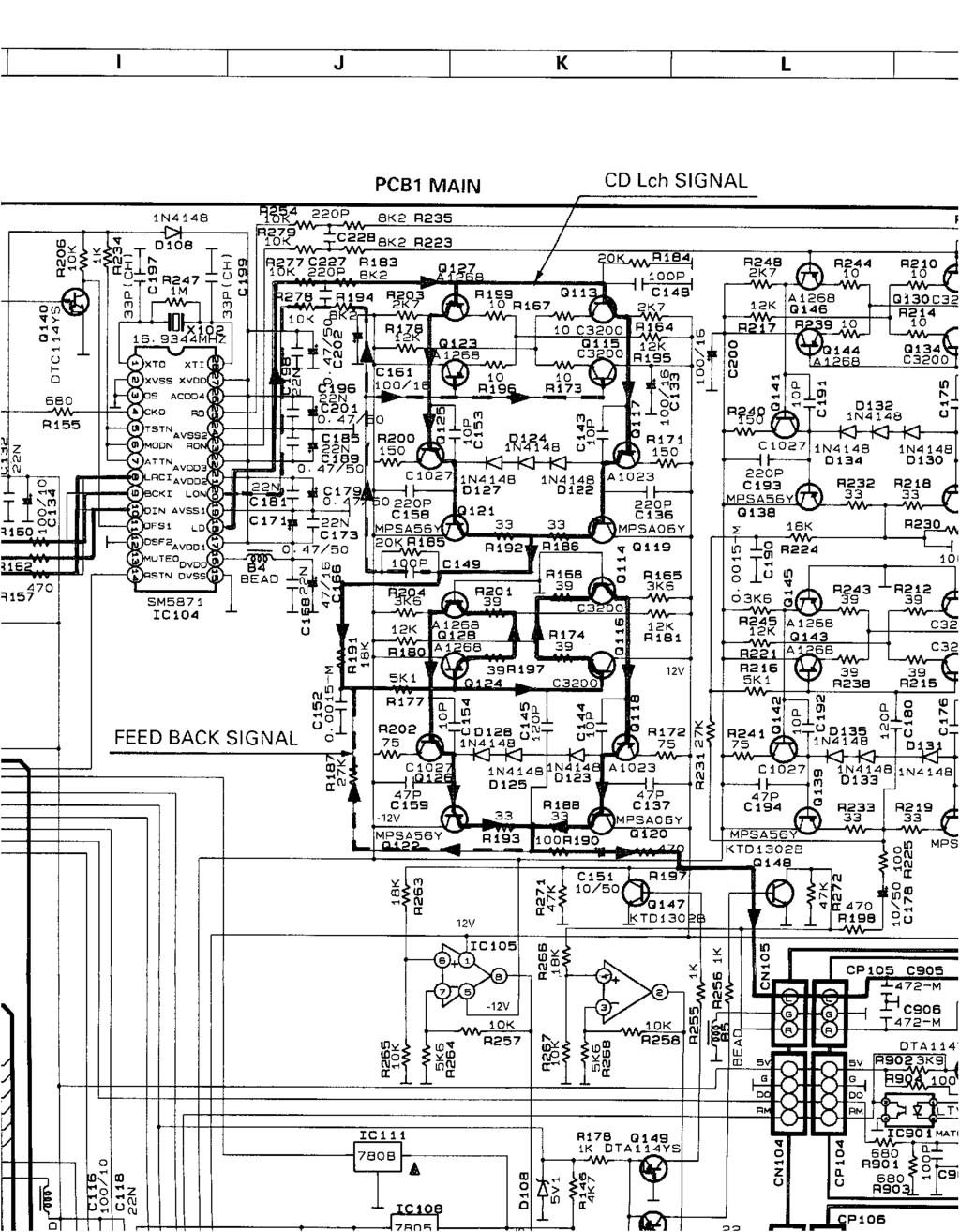
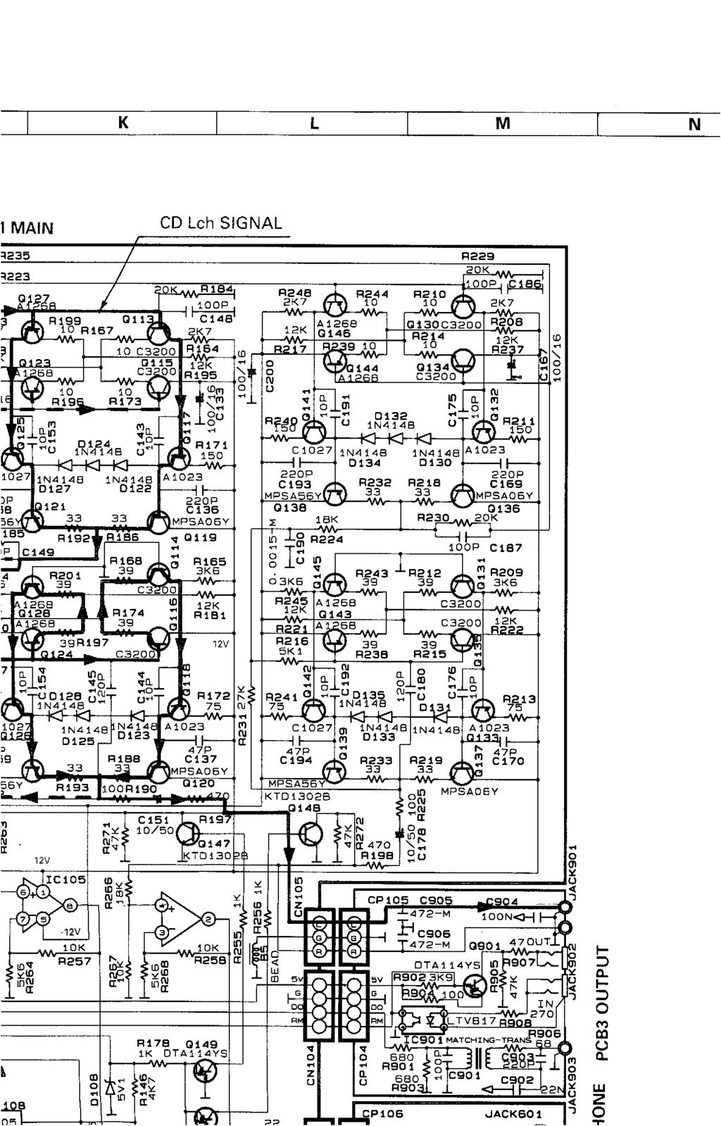
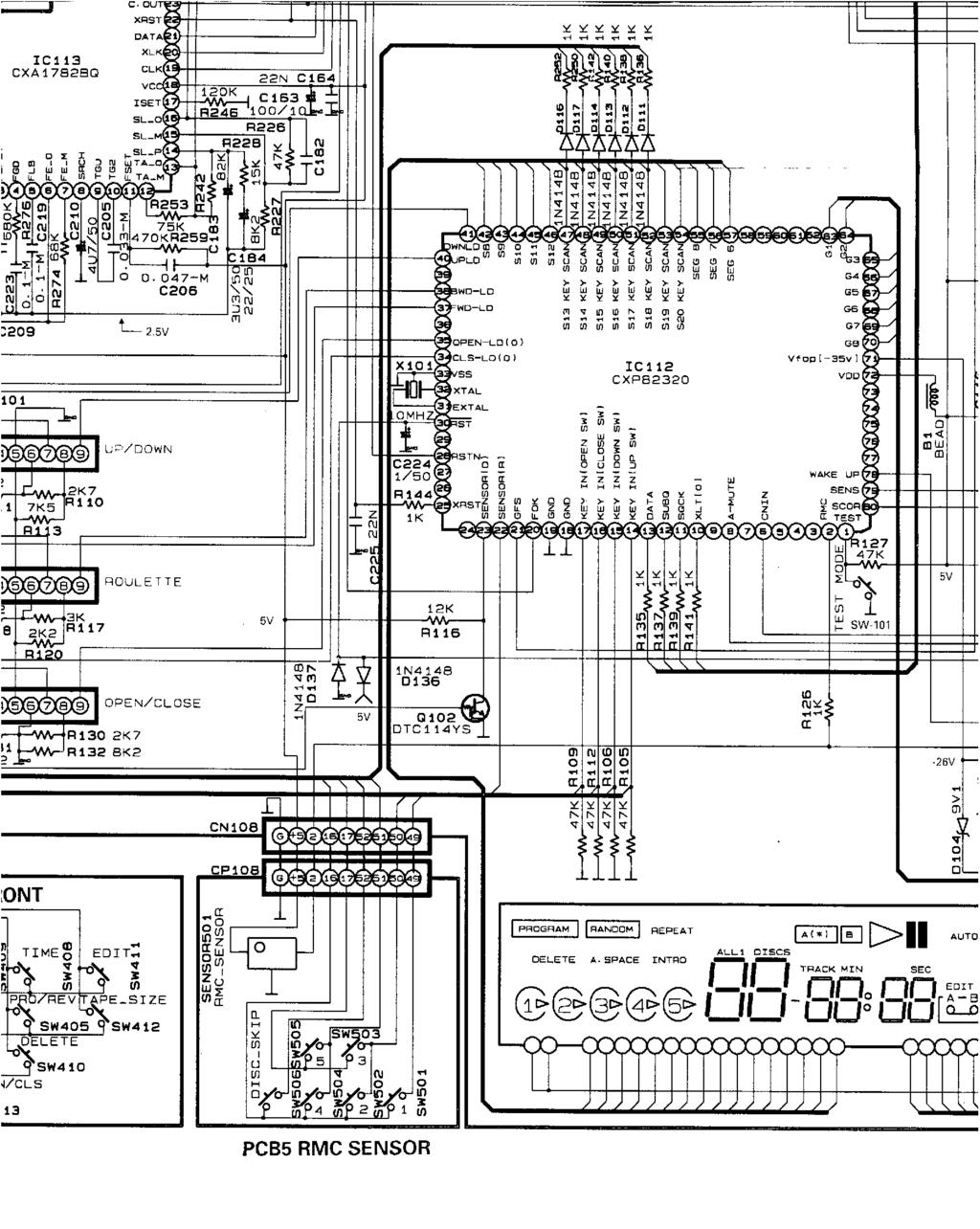
1 harman/kardon Model FL Disc Compact Disc Changer SERVICE MANUAL CONTENTS LASER BEAM SAFETY PRECAUTIONS...2 OTHER PRECAUTIONS LEAKAGE TEST SPEClFlCATlONS CONTROL AND FUNCTIONS BLOCK DIAGRAM PICKUP REPLACEMENT.. 11 CIRCUIT DESCRlPTlON BULLETIN # BULLETIN # BULLETIN # TECH TIP TIP# HKTT TROUBLESHOOTING PRINTED ClRCUlT BOARDS GENERAL UNIT EXPLODED VIEW I, II GENERAL UNIT PARTS LIST 40 ELECTRICAL PARTS LIST SEMICONDUCTOR IDENTIFICATION PACKAGE. 52 SCHEMATIC DIAGRAM WIRING DIAGRAM harman/kardon, Inc. 250 Crossways Park Dr. Woodbury, New York Rev1 3/2003
2
3
4
5
6
7
8
9
10
11
12
13
14
15
16
17
18
19
20
21
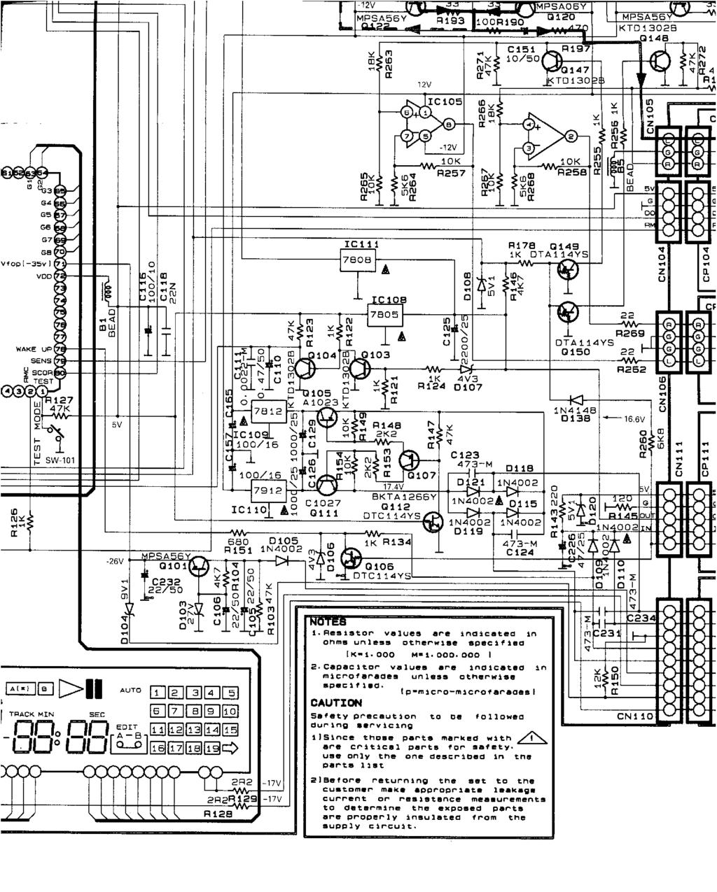
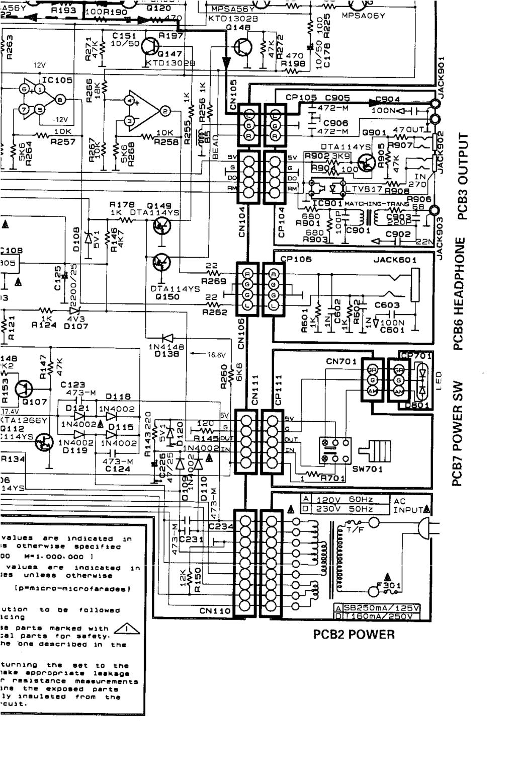
22 harman/kardon Service bulletin # 9604 rev1 - October 1998 Service Bulletin This is considered a Minor Repair To: All harman/kardon Service Centers Models: FL8300 Subject: Digital Output Level The Digital Interface Standard recommends D/A converters have a minimum Input sensitivity of 200 mv. In early FL8300 production units, the Digital Output level was 240 mv 10% peak to peak. Based on our research, we found that some D/A converters require more than 240 mv for intermittent free operation. In the event you receive a FL8300 from a consumer with the a complaint Intermittent Sound from External D/A converter, check the serial number in the table below. If the FL8300 has a serial number higher than indicated in the table below, connect a properly working D/A converter to the Digital Output and verify interruption free operation. Also confirm the Digital Output level of the FL8300 is 500 mv 10% Peak to Peak. If the FL8300 passes these two tests, advise the customer to have their external D/A converter and connecting cables checked. If the FL8300 has a serial number lower than indicated in the table below, perform the following modification: 1) With the unit plugged in and turned on, push the open/close button to extend the drawer fully; then turn the unit off and unplug it. 2) Open the top cover (6 screws). 3) Remove output board PCB3 from the rear panel (4 screws). This board can be pulled back and modified without completely removing it from the chassis. 4) Locate resistor R901, it may be a 680 ohm resistor or a jumper wire; replace in either case with a 0.47 uf capacitor h/k part# ) Locate R903 and change from 680 to a 4.7k resistor h/k part # Re-attach output PCB3 to the unit. 6) Connect a 75 Ohms cable to the digital output jack. Terminate this cable with a 75 Ohm load; connect an oscilloscope to the 75 Ohm termination resistor. While playing a CD, confirm the output of the signal is now 500 mv 10% peak to peak. 7) Reassemble the FL8300 and test all functions. Model FL8300 Serial number 120V IN to IN Serial number 230V IN to IN Status May have low digital output for some applications Action Replace R901 with 0.47 uf mylar capacitor h/k part# Replace R903 with 4.7k ohm resistor h/k part# FL8300 IN IN Factory Installed * NONE REQUIRED * Factory modification of the FL8300 starting with the serial numbers indicated in the above table consisted of: R236: 1k Ohm R901: Jumper or 680 Ohm R903: Changed from 680 Ohm to 4.7k Ohm. Digital output level into 75 Ohms: 500 mv 10% peak to peak.
23 harman/kardon Service bulletin # 9607-January 97 Service Bulletin This is considered a Major Repair To: All harman/kardon Service Centers Models: FL8300 Compact disc changer Subject: Failure to play Multi-media CDs or skip data tracks Early FL8300 CD Players used a micro-computer which could not read the table of contents (TOC) of certain multimedia CD s or skip data tracks on multimedia CD s. During two running production changes, new Microprocessor were installed which performs as shown in the table below: Description IC112 CXP DWP325 CXP Q DWP325A CXP Q DWP325B Part Number Serial number Range120V IN to IN IN to IN IN to present production Serial number Range230V IN to IN IN to IN IN to present production Processor action Does not play Multimedia CD Plays Multimedia CD, Mutes at data track Plays Multimedia CD, Skips data tracks Year/Month first used 95 October 96 July 96 November In the event you receive a FL8300 from a consumer with a complaint Player will not read or, loudspeakers make strange noise while playing multimedia CDs, replace IC112 with H/K Part number The IC can be identified by CXP Q DPW 325B printed on its case. harman/kardon Incorporated, 250 Crossways Park Dr. Woodbury, New York (516)
24 harman/kardon Service Bulletin Service bulletin # 9703 June 1997 This is considered a Major Repair To: All harman/kardon Service Centers Models: FL8300 Subject: Dead unit, no display; Service upgrade In the event you receive an FL8300 that is dead, and upon inspection R701 is damaged or an otherwise open circuit, perform the necessary steps listed below: Due to current surges, early models of the FL8300 could repeatedly damage R701 (either a 1 ohm resistor or 1.5A micro fuse depending on version). Along with the replacement of R701, the positive lead should be relocated on C125 to suppress any future current surges. Additionally, two capacitors, now designated as C907 & C908, (1uf/50v) should be added to the power supply output pins on regulator IC108 & IC111 on a unit serviced for any reason; these will add stability to help prevent oscillation. PROCEDURE: 1) Replace R701 with micro-fuse H/K # , this component is on PCB7. 2) A PCB trace should be cut on the C125 (2200 uf/25v) positive lead on the main circuit board and an insulated jumper wire attached from that lead to the junction of D109/110. Additionally another insulated jumper will need to replace the trace that was cut. (see drawing) 3) Add C907 & 908, 1uf/50v, H/K/ # , one on each output pin to ground on regulators IC108 and IC111. This is most easily accomplished by: Soldering one 1uf cap to the jumpers 153 & 197. Observe polarity; J153 is ground. Soldering one 1uf cap to the jumpers 185 & 186. Observe polarity; J186 is ground. Model FL8300 FL8300 Serial number 120V IN and below IN and above Serial number 230V NOT REQUIRED Action R701 is damaged or an open circuit Correction Replace R701, re-route positive connection on C125, Add C907/908 NOT REQUIRED Modified by factory NONE REQUIRED harman/kardon Incorporated, 250 Crossways Park Dr. Woodbury, New York (516)
25 harman/kardon Incorporated, 250 Crossways Park Dr. Woodbury, New York (516)
26 harman/kardon TECH TIPS Troubleshooting tips and solutions to common service problems For models: FL8300 TIP# HKTT Problem: "Carousel not stopping in the correct position, so disc can be clamped correctly". Check: 1) 6-conductor Ribbon cable connection to sensor board - check cable; clean, re-seat at both ends. 2) There is a post/standoff underneath the single center screw in the center of the carousel (under the plastic 1,2,3,4,5 cap). If that post/standoff is too long, it can cause the symptom. If the part is higher than the surface of the carousel in that area, the part needs to be shaved down so it's shorter. 3) Defective Roulette sensor (part# ) or Disc sensor (part# ).
27
28
29
30
31
32
33
34

35
36
37
38
39
40

41

42
43
44
45
46
47
48
49
50
51
52
53
54
55
56
57
58
59
60
61
62
63
64
65
66
67
68
SERVICE BULLETIN. Description: VOX\ICS Tie Line Subassembly Document #: AMS44\603-0 Service Bulletin #: 002
 SERVICE BULLETIN NAT Part #: AMS44 Description: VOX\ICS Tie Line Subassembly Document #: AMS44\603-0 Service Bulletin #: 002 1. Planning Information 1.1 Applicability All dual channel audio controllers:
Audio Restoration Repair Bose Wave Music System AWRCC1 AWRCC2 AWRCC7
 Audio Restoration Repair Bose Wave Music System AWRCC1 AWRCC2 AWRCC7 This applies to the Wave Music System, Wave Music System II, Wave Music System III, in all AC voltage variations. These particular versions,
Instruction Manual. SSQ-2F Controller Board. For the. v1.41 For Rife Plasma Tube Systems. Manual v by Ralph Hartwell Spectrotek Services
 Instruction Manual For the SSQ-2F Controller Board v1.41 For Rife Plasma Tube Systems Manual v1.00 2012 by Ralph Hartwell Spectrotek Services This page intentionally blank. 2 Index and Table of Contents
SSRP LTC1746 Assembly Manual V0.1 Check the most recent version
 SSRP LTC1746 Assembly Manual V0.1 Check the most recent version http://oscar.dcarr.org/ssrp/hardware/ltc1746/ltc1746.php Introduction This manual details the general assembly process for the SSRP LTC1746
MASTERFLEX L/S ECONOMY 200 RPM DRIVE 115 VOLT MASTERFLEX L/S ECONOMY 200 RPM DRIVE 230 VOLT
 MODELS: ********SERVICE MANUAL******** 7554-80 MASTERFLEX L/S ECONOMY 200 RPM DRIVE 115 VOLT 7554-85 MASTERFLEX L/S ECONOMY 200 RPM DRIVE 230 VOLT 7554-90 MASTERFLEX L/S ECONOMY 600 RPM DRIVE 115 VOLT
TABLE OF CONTENTS. 1) Introduction 2. 2) Unpacking your preamplifier 2. 3) Installing the preamp into your system 3
 Introduction 2. 2) Unpacking your preamplifier 2. 3) Installing the preamp into your system 3") TABLE OF CONTENTS 1) Introduction 2 2) Unpacking your preamplifier 2 3) Installing the preamp into your system 3 4) Operation of your preamplifier 6 5) Troubleshooting 8 6) Registration of your preamplifier
TABLE OF CONTENTS 1) Introduction 2 2) Unpacking your preamplifier 2 3) Installing the preamp into your system 3 4) Operation of your preamplifier 6 5) Troubleshooting 8 6) Registration of your preamplifier
ABC V1.0 ASSEMBLY IMPORTANT!
 ABC V1.0 ASSEMBLY Before starting this kit, prepare the following tools: Soldering iron (15-20W will do), flush cutters, no.2 hex screwdriver or allen key and phillips screwdriver. Also briefly go through
Easy Transmitter. Support ETX_REV5_Manual V2.7 Revised
 Easy Transmitter Introduction The Easy Transmitter kit from qrpkits.com provides a basic, crystal controlled transmitter with VXO tuning to provide a small tuning range around the crystal frequency. It
SoftRock v5.0 Builder s Notes. December 12, Building a QSD Kit
 SoftRock v5.0 Builder s Notes December 12, 2005 Building a QSD Kit Be sure to use a grounded tip soldering iron in building the QSD board. The soldering iron needs to have a small tip, (0.05-0.1 inch diameter),
555 Morse Code Practice Oscillator Kit (draft 1.1)
") This kit was designed to be assembled in about 30 minutes and accomplish the following learning goals: 1. Learn to associate schematic symbols with actual electronic components; 2. Provide a little experience
This kit was designed to be assembled in about 30 minutes and accomplish the following learning goals: 1. Learn to associate schematic symbols with actual electronic components; 2. Provide a little experience
Analog Technologies. Auto Iron ATAS80
 Figure 1. The Photo of main machine Figure 2. Photo of MAIN FEATURES Large LCD screen display, convenient for adjusting Anti-static function to protect precise chip soldering Quick temperature rise Unit
Worldwide Manufacturer of Gas Detection Solutions. Transmitter EC 23. Operation Manual
 Worldwide Manufacturer of Gas Detection Solutions Transmitter EC 23 Operation Manual Table of Contents For Your Safety...4 General Description...4 Electrical Connections...5 Zero Point Adjustment...5
Read This Page First
 Read This Page First If you are reading this you know the manuals are always available at QRPKITS.com. This is version 8.0 of the manual dated 4/27/2016. There is no need to print out the whole assembly
Ten Tec DDS Board Assembly Procedure
 05 May 2014 Ten Tec DDS Board Assembly Procedure You will find a photo of a completed board at the end of these instructions. Refer it whenever clarification is required. 1. AD9835 Attachment If you purchased
Code Practice Oscillator (CPO) For kit building instructions turn to Page 3.
 For kit building instructions turn to Page 3.") Code Practice Oscillator (CPO) For kit building instructions turn to Page 3. Overview Many thanks for your purchase of this code practice oscillator or CPO, this guide is intended to allow you to quickly
Code Practice Oscillator (CPO) For kit building instructions turn to Page 3. Overview Many thanks for your purchase of this code practice oscillator or CPO, this guide is intended to allow you to quickly
SoftRock v6.0 Builder s Notes. May 22, 2006
 SoftRock v6.0 Builder s Notes May 22, 2006 Be sure to use a grounded tip soldering iron in building the v6.0 SoftRock circuit board. The soldering iron needs to have a small tip, (0.05-0.1 inch diameter),
Manual of ELMB_MB v modifications for technicians.
 ELMB_MB_v6.5.3_manual.doc 1/11 Manual of ELMB_MB v.6.5.3 modifications for technicians. B. Palan, A. Tikhonov Date: 14 Feb 2007 bpalan@cern.ch Pages: 11 Summary: This document describes the component changes
Penrose Quantizer Assembly Guide
 Penrose Quantizer Assembly Guide Schematic and BOM The schematic can be found here: www.sonic-potions.com/public/penrosequantizerschematic.pdf The BOM is available at google docs: Link to BOM Prepare the
WJ-8617B and WJ-8618B HF Upgrades: 500 KHz to 1100 MHz By: Stephen Pappin
 WJ-8617B and WJ-8618B HF Upgrades: 500 KHz to 1100 MHz By: Stephen Pappin The typical frequency coverage for an 8617B or 8618B is from 20 MHz to 1100 MHz (500 MHz without FE). These versions have pre selectors
Experiment 3 Ohm s Law
 Experiment 3 Ohm s Law The goals of Experiment 3 are: To identify resistors based upon their color code. To construct a two-resistor circuit using proper wiring techniques. To measure the DC voltages and
INSTALLATION MANUAL FOR 2U MODIFICATION KIT
 FOR 2U054-001 MODIFICATION KIT Kit for modification of ARC Type 385A Communication -Navigation System; (Extended COM Frequency Range: 118.000 to 136.975 MHz) Publication. No. 86M016 OCTOBER 1992 LIST OF
Repairing your Porsche 928 Central Warning System (CWS) controller
 controller") Repairing your Porsche 928 Central Warning System (CWS) controller Disclaimer: This procedure is for a 1984 Porsche 928 S controller. Overview: Under the left foot pedal (dead pedal) of the Porsche 928
Repairing your Porsche 928 Central Warning System (CWS) controller Disclaimer: This procedure is for a 1984 Porsche 928 S controller. Overview: Under the left foot pedal (dead pedal) of the Porsche 928
NEO CAR AUDIO. Neo AUXiN AUX INPUT INTERFACE. Instruction Manual
 NEO CAR AUDIO Neo AUXiN AUX INPUT INTERFACE Instruction Manual IMPORTANT NOTE Neo AUXiN Dip switch positions MUST be set BEFORE any other step is taken. Otherwise, the kit will not operate properly. See
DIY Tube Stereo 70 Board - TubeZone Assembled -Instructions - Page 1
 DIY Tube Stereo 70 Board - TubeZone Assembled -Instructions - Page 1 Board and portions of manual, (c) 2006 Shannon Parks & DIYtube.com. Version specific instructions (c) 2006 Ned Carlson and Tubezone.net
A Repeater for the NCE Radio System By Mark Schutzer January 6, 2005
 A Repeater for the NCE Radio System By Mark Schutzer January, 00 Introduction: This is a follow on to my earlier write up that described a diversity receiver for the NCE radio system. In this write up
Assembly Manual for VFO Board 2 August 2018
 Assembly Manual for VFO Board 2 August 2018 Parts list (Preliminary) Arduino 1 Arduino Pre-programmed 1 Faceplate Assorted Header Pins Full Board Rev A 10 104 capacitors 1 Rotary encode with switch 1 5-volt
Data Conversion and Lab Lab 4 Fall Digital to Analog Conversions
 Digital to Analog Conversions Objective o o o o o To construct and operate a binary-weighted DAC To construct and operate a Digital to Analog Converters Testing the ADC and DAC With DC Input Testing the
PLEASE READ BEFORE STARTING INSTALLATION
 PLEASE READ BEFORE STARTING INSTALLATION The N-Tune Artist Series chromatic tuner assembly replaces the 500k volume control and toggle switch of your electric guitar or bass It can be installed by experienced
The LZA2027 Tone Termination Panel Instruction and Programming Manual
 The LZA2027 Tone Termination Panel Instruction and Programming Manual BK Radio 7100 Technology Drive West Melbourne, FL 32904 Phone: (800) 648-0947 Fax: (321) 984-0434 www.relm.com 0300-30944-900 Rev.
Pingable Envelope Generator
 Pingable Envelope Generator Kit Builder's Guide for PCB v1.0.3 4mspedals.com PEG This guide is for building a Pingable Envelope Generator (PEG), which is an intermediate-level kit. You should be confident
BELSON. BSA-1061 (2 W remote) MICRO COMPONENT SYSTEM
 MICRO COMPONENT SYSTEM") BELSON (2 W remote) MICRO COMPONENT SYSTEM MODEL CAUTION: Before servicing the chassis, read the " important service safety information" section on page 2 of this manual. MICRO HI-FI STEREO RADIO WITH
BELSON (2 W remote) MICRO COMPONENT SYSTEM MODEL CAUTION: Before servicing the chassis, read the " important service safety information" section on page 2 of this manual. MICRO HI-FI STEREO RADIO WITH
CD770 DIGITAL MULTIMETER INSTRUCTION MANUAL
 CD770 DIGITAL MULTIMETER INSTRUCTION MANUAL Table of Contents 1 SAFETY PRECAUTIONS Before use, read the following safety precautions.- 1-1 Explanation of Warning Symbols 001 1-2 Warning Messages for Safe
AUDIO SYSTEMS 8F - 1 AUDIO SYSTEMS CONTENTS
 TJ AUDIO SYSTEMS 8F - 1 AUDIO SYSTEMS CONTENTS page GENERAL INFORMATION INTRODUCTION... 1 DESCRIPTION AND OPERATION ANTENNA... 1 IGNITION-OFF DRAW FUSE... 1 RADIO... 1 RADIO NOISE SUPPRESSION... 2 SPEAKER...
INSTRUCTION MANUAL LKG 601 Electrical Safety Analyzer
 INSTRUCTION MANUAL LKG 601 Electrical Safety Analyzer 110 Toledo Street Farmingdale, NY 11735 USA http://www.netech.org 510-USER-Manual Rev3 10/29/2007 Dear User, We appreciate your purchase of the LKG
Sigma 5 - Axis Servo Motor and Cables - Troubleshooting Guide
 LAST UPDATED: 09/24/2018 Electrical Safety Caution: When you do maintenance or repair on CNC machines and their components, you must always follow basic safety precaut and mechanical damage. Set the main
Sigtronics Auto Squelch Intercom System Installation and Operating Instructions Models SAS-440 and SAS-640
 Sigtronics Auto Squelch Intercom System Installation and Operating Instructions Models SAS-440 and SAS-640 INTRODUCTION ATTENTION INSTALLER: To assure a trouble free installation, please read the entire
INSTALLATION AND MAINTENANCE MANUAL FOR GROUND MONITOR GM-250 COPYRIGHT 1983 AMERICAN MINE RESEARCH, INC.
 INSTALLATION AND MAINTENANCE MANUAL FOR GROUND MONITOR GM-250 COPYRIGHT 1983 AMERICAN MINE RESEARCH, INC. MANUAL PART NUMBER 180-0036 ORIGINAL: 1-17-83 REVISION: B (8-26-86) NOT TO BE CHANGED WITHOUT MSHA
3 CHANNEL DUAL / TRIPLE RECTIFIER SOLO HEAD
 3ch Head 3 CHANNEL DUAL / TRIPLE RECTIFIER SOLO HEAD FRONT PANEL CHANNEL 1 (GREEN) CHANNEL 2 (ORANGE) Control Function Type Mesa Part# Control Function Type Mesa Part# Gain Pot 593792 Gain Pot 592794 Knob
Manual of ELMB_MB v modifications for technicians.
 ELMB_MB_v6.5.2_manual.doc 1/10 Manual of ELMB_MB v.6.5.2 modifications for technicians. B. Palan, A. Tikhonov, A. Solin Date: 10 Jan 2007 bpalan@cern.ch Pages: 10 Summary: This document describes the component
Instruction Kit MIXER AMPLIFIER GT 60C GT 125C. GROMMES-PRECISION SINCE-46
 Instruction Kit GT 60C GT 125C MIXER AMPLIFIER GROMMES-PRECISION 1-800-SINCE-46 www.grommesprecision.com Thank you for purchasing from Grommes~Precision! Grommes~Precision and its commercial audio division,
Understanding & Using The HA2500's Sub Drives
 Understanding & Using The HA2500's Sub Drives When horizontal drive to the horizontal output stage is missing, expensive horizontal output stage components cannot be determined good or bad. If horizontal
Ameritron ALS-600 Retrofit ALS-600-LPF Assembly Manual
 Ameritron ALS-600 Retrofit ALS-600-LPF Assembly Manual FEATURES Automatic band change based on TX frequency. PIN diode QSK RX/TX switch. Temperature controlled FAN for quiet operation. RS-232 serial port
Model 1152-ALN Phase Locked Oscillator
 Model 1152-ALN Phase Locked Oscillator The Model 1152-ALN is a single frequency, very low Phase Noise PLL unit that can be used to replace your unstable microwave crystal oscillator chain with a stable
Manual Version July 2007
 Manual Version 1.2 - July 2007 Page 1 Table of Contents Section1: M3 Phono Board Build...3 Phono Board Parts List...3 Preparation...4 Fitting the Valve Bases...6 Installing the Resistors...7 Starting the
USER MANUAL VIVALDI MZ550A. Distribution Mixer Amplifier
 USER MANUAL VIVALDI MZ550A Distribution Mixer Amplifier 1. Security Precautions Carefully READ the instruction in this manual before use. Be sure to OBSERVE the INSTRUCTION in this manual regard convention
HAMTRONICS TB901 FM EXCITER INSTALLATION, OPERATION, & MAINTENANCE
 HAMTRONICS TB901 FM EXCITER INSTALLATION, OPERATION, & MAINTENANCE GENERAL INFORMATION. The TB901 is a single-channel low power fm transmitter (exciter) designed to provide 300-600 milliwatts continuous
ALX-SSB 5 Band Filter Assembly Manual 19 November 2018
 ALX-SSB 5 Band Filter Assembly Manual 19 November 2018 Contents Theory of Operation:... 1 Figure 1... 2 Parts Included:... 4 Board Overview:... 5 Figure 2... 5 Figure 3... 5 Board Assembly:... 6 Cable
SoftRock v6.0 Builder s Notes. April 6, 2006
 SoftRock v6.0 Builder s Notes April 6, 006 Be sure to use a grounded tip soldering iron in building the v6.0 SoftRock circuit board. The soldering iron needs to have a small tip, (0.05-0. inch diameter),
BU80 BU80E HTS-10 POWERED SUBWOOFER SERVICE MANUAL
 BU80 BU80E HTS-10 POWERED SUBWOOFER SERVICE MANUAL Infinity Systems, Inc. 250 Crossways Park Dr. Woodbury, New York 11797 Rev H 11/2001 BU-80/BU80E/HTS-10 SAFETY INFORMATION/VERSION DIFFERENCES Warning
Explosion Proof Page/Talk Paging Amplifier
 Industrial Communications Worldwide Explosion Proof Page/Talk Paging Amplifier Installation & Operation 7552-10 th Street. N.E. Calgary Alberta, Canada T2E W1 Ph: 403.25.3100 \ email:info@guardiantelecom.com
INTERNATIONAL RADIO CORP
 I N R A D INTERNATIONAL RADIO CORP 13620 Tyee Road Umpqua, OR 97486 (541) 459-5623 fax (541) 459 5632 E-mail: inrad@rosenet.net www.qth.com/inrad IC-775 ROOFING FILTER INSTALLATION INSTRUCTIONS The IC-775
SureTest Model ST-1THD & ST-1THDC Instructions
 #61-156 #61-157 #61-158 SureTest Model ST-1THD & ST-1THDC Instructions Introduction The SureTest family of Circuit/distortion analyzers identify problems common to electrical circuits and harmonic distortion
Four Channel Inductive Loop Detector
 Naztec Operations Manual For Four Channel Inductive Loop Detector Model 724/224 April 2003 Published by: Naztec, Inc. 820 Park Two Drive Sugar Land, Texas 77478 Phone: (281) 240-7233 Fax: (281) 240-7238
NCS-C150 INSTRUCTION MANUAL Rev A. Collcomm Inc. Shipping Address 2310 Pendley Road Cumming, Georgia 30041
 NCS-C150 INSTRUCTION MANUAL Rev A Collcomm Inc. d.b.a. NCS Shipping Address 2310 Pendley Road Cumming, Georgia 30041 Mailing Address 1595 Peachtree Parkway Suite 204-123 Cumming, Georgia 30041 Toll Free
BAUR Prüf- und Messtechnik GmbH Raiffeisenstrasse 8 A-6832 Sulz/Austria T. +43/5522/ F +43/5522/
 BAUR Prüf- und Messtechnik GmbH Raiffeisenstrasse 8 A-6832 Sulz/Austria T. +43/5522/4941-0 F +43/5522/4941-3 service@baur.at www.baur.at Print date: 04.05.2005 Service Manual High Voltage Generator PGK
20-27B. Tone Panel. Version 1.10
 20-27B Tone Panel Version 1.10 Printings Version 1.00: 1/16/01 Version 1.10: 10/11/02 TABLE OF CONTENTS SPECIFICATIONS... 1 1.0 GENERAL DESCRIPTION... 2 1.1 Description... 2 1.2 Capabilities and Features...
User s Manual Current Probe. IM E 1st Edition. Yokogawa Electric Corporation
 User s Manual 701932 Current Probe Yokogawa Electric Corporation 1st Edition Foreword Revisions Thank you for purchasing the 701932 Current Probe. This user's manual contains useful information about the
AC/DC Clamp Meter. Owner's Manual. Model No Safety Operation Maintenance Español
 Owner's Manual AC/DC Clamp Meter Model No. 82369 CAUTION: Read, understand and follow Safety Rules and Operating Instructions in this manual before using this product. Safety Operation Maintenance Español
LESLIE CONSOLE CONNECTOR KIT 8400 INSTALLATION INSTRUCTIONS
 LESLIE CONSOLE CONNECTOR KIT 8400 INSTALLATION INSTRUCTIONS FOR USE WITH: LESLIE Speaker Models: 122, 122RV, 222, or 222RV in conjunction with HAMMOND Speaker HAMMOND Organ Models: A, B, C, D, E, RT, BV,
! February 9, 1970 GR-78!! Bulletin No: Transistor General Coverage Rcvr!
 ! February 9, 1970 GR-78-1! Rocker Switches [PN 60-45] S.P.S.T. switch is being replaced by [PN 60-48] D.P.D.T. switch with improved contacts. Four of the six lugs are removed when it is used as a S.P.S.T.
DO NOT PULL ON THE SHEATH.
 Removing and Replacing the Head Cover To remove and replace the head cover you will need the following tools: #2 Phillips screwdriver (magnetic tip preferred) Removing the Head Cover 1. Ready the machine
PARALLEL MULTI-AMP KIT for 7200 Series AMPLIFIERS INSTRUCTION SHEET
 2 5 0 7 W a r r e n S t r e e t, E l k h a r t, I N 4 6 5 1 6 U S A 5 7 4. 2 9 5. 9 4 9 5 w w w. A E T e c h r o n. c o m PARALLEL MULTI-AMP KIT for 7200 Series AMPLIFIERS INSTRUCTION SHEET Kit Contents:
Starving Student II. Starving Student II. SS2 guide. Written By: 6L guides.diyaudio.com/ Page 1 of 24
 SS2 guide Written By: 6L6 2019 guides.diyaudio.com/ Page 1 of 24 INTRODUCTION This is a build guide for the hybrid headphone/pre-amplifier. You can buy a kit at the SSII product listing on the diyaudio
Ultrasound Range Finder
 Ultrasound Range Finder PCB Version 1.0 Assembly Manual Range Finder Assembly Instructions Read This Before You Begin 1. Avoid touching the PCB copper traces and pads with your fingers until you are ready
Assembly and Installation Instructions for White Oak Audio Design TM-1001 LED board
 Thank you for purchasing White Oak Audio Design s TM-1001 Upgrade LED Light Board. White Oak Audio Design products are meticulously engineered and tested to ensure a direct drop in fit with your tuner.
Pacific Antenna Field Strength Indicator Kit
 Pacific Antenna Field Strength Indicator Kit Description The Field Strength Indicator kit from Pacific Antenna provides a visual way to monitor the presence and relative strength RF fields through the
NCS-C150 INSTRUCTION MANUAL Rev D. Collcomm Inc. d.b.a. NCS. Shipping Address 2310 Pendley Road Cumming, Georgia 30041
 NCS-C150 INSTRUCTION MANUAL Rev D Collcomm Inc. d.b.a. NCS Shipping Address 2310 Pendley Road Cumming, Georgia 30041 Mailing Address 1595 Peachtree Parkway Suite 204-123 Cumming, Georgia 30041 Toll Free
New Life for the AM6154 and AM6155 John, W1AN 29 July, 2014
 New Life for the AM6154 and AM6155 John, W1AN 29 July, 2014 There are numerous sources for conversion information and modifications that have been shared over the years for the FAA AM6154 and AM6155 amplifiers
PC to Radio Audio and Key-line Interface
 PC to Radio Audio and Key-line Interface Background - This simple interface was developed to capacitive couple audio signals between a radio and PC, to provide a means of adjusting audio levels between
ELECRAFT Application Note
 ELECRAFT Application Note Front Panel Microphone Circuit Modification Revision A, November 12, 2008 Copyright 2008, Elecraft, Inc., All Rights Reserved Background Some K3 owners have noted distorted transmit
DC1000 (120VAC) Theory of Operations
 Theory of Operations") DC1000 (120VAC) Theory of Operations The DC1000 is a dynamic DC treadmill designed for a wide range of applications that vary from the medical market to the sports performance market. This theory of operation
DC1000 (120VAC) Theory of Operations The DC1000 is a dynamic DC treadmill designed for a wide range of applications that vary from the medical market to the sports performance market. This theory of operation
SERIES. Owners Manual & Installation Guide. Limited Warranty: 2-Channel High Speed Digital Stereo Amplifier
 Limited Warranty: RE Audio warrants all manufactured electronic products to be free from defects in material and workmanship for a period not to exceed ONE YEAR from the date of purchase. 2-Channel High
IDEAL INDUSTRIES, INC. TECHNICAL MANUAL MODEL:
 IDEAL INDUSTRIES, INC. TECHNICAL MANUAL MODEL: 61-920 The Service Information provides the following information: Precautions and safety information Specifications Performance test procedure Calibration
MultiPac 24 in 1 Installation Guide and User s Manual
 MultiPac 24 in 1 Installation Guide and User s Manual Notice Regarding this Upgrade Warning! Although this upgrade has been tested and the techniques used will not directly cause harm to your video game,
INSTALLATION INSTRUCTIONS FOR THE CLIKCARD COMMERCIAL RECEIVER (NARROW BAND)
") Doc. 6001200 Rev. B INSTALLATION INSTRUCTIONS FOR THE CLIKCARD COMMERCIAL RECEIVER (NARROW BAND) TABLE OF CONTENTS TABLE OF CONTENTS...1 INSTALLATION FOR INFINITY AND PROCARD...3 PULLING CABLE... 3 MOUNTING
Doc. 6001200 Rev. B INSTALLATION INSTRUCTIONS FOR THE CLIKCARD COMMERCIAL RECEIVER (NARROW BAND) TABLE OF CONTENTS TABLE OF CONTENTS...1 INSTALLATION FOR INFINITY AND PROCARD...3 PULLING CABLE... 3 MOUNTING
PRACTICAL ELECTRONICS TROUBLESHOOTING
 PRACTICAL ELECTRONICS TROUBLESHOOTING Second Edition James Perozzo 4 k 0 DELMAR PUBLISHERS INC. Contents Preface/xiii chapter one Some Necessary Basics Chapter Overview/1 Necessary Background/1 A Few Definitions/6
S&T GeoTronics LLC Open DSKY with AGC Assembly Instructions
 S&T GeoTronics LLC Open DSKY with AGC Assembly Instructions First, make sure you have all the required components: HARDWARE Qty Item 1 DSKY PCB v1.0d 1 Arduino Nano 1 VA RTC 1 IMU 1 Buck StepDown 1 SKM53
LITTLE NERD v1.1 Assembly Guide
 last update: 9. 3. 2016 LITTLE NERD v1.1 Assembly Guide bastl instruments.com INTRODUCTION This guide is for building Little Nerd module from Bastl Instruments. It is good to have basic soldering skills
SMT REVERSE POLARITY PROTECTION
 SMT REVERSE POLARITY PROTECTION We have all done it, or will one day, hook the power cables to the radio backwards. Hopefully little to nothing will happen. Sometimes it s a minor repair like replacing
Modification of USB Sound Card for Asterisk app_rpt Use
 Modification of USB Sound Card for Asterisk app_rpt Use First off a huge thank you to Steve for providing the original notes on how to modify a USB sound card. (http://images.qrvc.com/usbfob.pdf) These
 Page 1 of 6 Page 1 of 12 Yaesu FT-5100/FT-5200 MODS Rev B (14 Apr 1993) This is a collection of hardware and software mods for the Yaesu 5100/5200 pair. I have the 5100, so I can't verify these for the
NCS-C151 INSTRUCTION MANUAL Rev B. Collcomm Inc. d.b.a. NCS. Shipping Address 2310 Pendley Road Cumming, Georgia 30041
 NCS-C151 INSTRUCTION MANUAL Rev B Collcomm Inc. d.b.a. NCS Shipping Address 2310 Pendley Road Cumming, Georgia 30041 Mailing Address 1595 Peachtree Parkway Suite 204-123 Cumming, Georgia 30041 Toll Free
McPherson Voltage Regulators 4501 NW 27 Ave Miami FL
 McPherson Voltage Regulators 4501 NW 27 Ave Miami FL 33142 305-634-1511 To avoid of possible personal injury or equipment damage read and understand this manual before installation. (A.V.R) 208 / 380 /
Specialists in HV and MV test and diagnostics. Testing in Substations
 Specialists in HV and MV test and diagnostics Testing in Substations Testing in Substations Testing in Substations At 4fores we specialize in the diagnosis and measurement of all types of existing technologies
Instruction Manual. CT101 line stage / linear preamplifier module
 CT0 line stage / linear preamplifier module CT0 CONTENT UNPACKG channel line stage / linear preamplifier module Unpacking Connections Definitions Power supply Signal input Signal output Volume control
Customer Service Bulletin SD Upgrade to SLP45400 Low Voltage/High Voltage Power Supply PCB
 Customer Service Bulletin SD800003 Upgrade to SLP45400 Low Voltage/High Voltage Power Supply PCB Continual Improvement is a cornerstone of the Southern Avionics Company Quality Management System. We issue
OPERATION & SERVICE MANUAL FOR FC 110 AC POWER SOURCE
 OPERATION & SERVICE MANUAL FOR FC 100 SERIES AC POWER SOURCE FC 110 AC POWER SOURCE VERSION 1.3, April 2001. copyright reserved. DWG No. FC00001 TABLE OF CONTENTS CHAPTER 1 INTRODUCTION... 1 1.1 GENERAL...
Warm Tube Clock. Before we start, please make sure that you have all required parts that come for the main board :
 Warm Tube Clock Assembly Instructions for the main board Introduction Congratulations on your purchase of OSH Nixie Tube Clock. In this document you will see all steps you need to follow in order to successfully
audionet AMP 1 V2 User s Manual Stereo - Amplifier
 audionet AMP 1 V2 Stereo - Amplifier User s Manual 1 2 Contents 1 Preface... 4 1.1 Included... 5 1.2 Transport... 5 2 Overview control elements... 6 2.1 Front panel... 6 3 Overview connections... 7 3.1
INSTALLATION MANUAL FOR 2U EXTENDED FREQUENCY RANGE MODIFICATION KIT
 FOR 2U57- EXTENDED FREQUENCY RANGE MODIFICATION KIT Kit for modification of ARC Type 38A Communication System; (Extended COM Frequency Range: 8. to 36.975 MHz) Part Number Change: From: To: RT-38A - Standard:
Radio Control Installation and Operating Instructions System 4
 Radio Control Installation and Operating Instructions System 4 P.O. Box 403, One Cedar Parkway, Jackson, WI 53037 Phone: 800-628-1909 Fax: 262-677-2058 Revision: April 19, 2012 Contents Introduction 3
MODEL W Power Amplifier
 TEGAM, INC. MODEL 2348 18.75 W Power Amplifier This owner s manual was as current as possible when this product was manufactured. However, products are constantly being updated and improved. Because of
SPACE WAR GUN KIT MODEL K-10. Assembly and Instruction Manual. Elenco Electronics, Inc.
 SPACE WAR GUN KIT MODEL K-10 Assembly and Instruction Manual Elenco Electronics, Inc. Copyright 1989 Elenco Electronics, Inc. Revised 2001 REV-H 753210A PARTS LIST Contact Elenco Electronics (address/phone/e-mail
TEGAM, INC. SINGLE/DUAL CHANNEL HIGH VOLTAGE AMPLIFIER MODEL 2340/2350. Instruction Manual PN# CD Publication Date: June 2006 REV.
 TEGAM, INC. SINGLE/DUAL CHANNEL HIGH VOLTAGE AMPLIFIER MODEL 2340/2350 Instruction Manual PN# 810044-CD Publication Date: June 2006 REV. C This owner s manual was as current as possible when this product
Building a Bitx20 Version 3
 Building a Bitx20 Version 3 The board can be broken into sections and then built and tested one section at a time. This will make troubleshooting easier as any problems will be confined to one small section.
Value Location Qty Potentiometers C1M Distortion 1 A10k Volume 1. Footswitch 3PDT SW1 1. Jacks 1/4 Mono 2 DC Power 1
 Distortion BUILD INSTRUCTIONS Thank you for your purchase of our Distortion+ kit! We have completely redesigned our entire line of kits to be the most user friendly, while still maintaining their same
Build Your Own Clone Kuzco Jr. Kit Instructions
 Build Your Own Clone Kuzco Jr. Kit Instructions Warranty: BYOC, Inc. guarantees that your kit will be complete and that all parts and components will arrive as described, functioning and free of defect.
TS-850: Installing the Inrad Roofing Filter Mod
 TS-850: Installing the Inrad Roofing Filter Mod The TS-850 Roofing Filter Mod consists of a 6 pole, 4 to 5 khz wide filter followed by a high dynamic range feedback amplifier. The amplifier provides enough
DIODE / TRANSISTOR TESTER KIT
 DIODE / TRANSISTOR TESTER KIT MODEL DT-100K Assembly and Instruction Manual Elenco Electronics, Inc. Copyright 1988 Elenco Electronics, Inc. Revised 2002 REV-K 753110 DT-100 PARTS LIST If you are a student,
American Audio. User Instructions. American Audio 4295 Charter Strret Los Angeles Ca Revised 5/01
 American Audio User Instructions American Audio 4295 Charter Strret Los Angeles Ca. 90058 Revised 5/01 CAUTION Do not open - risk of electric shock CAUTION: TO REDUCE THE RISK OF ELECTRIC SHOCK, DO NOT