SMT REVERSE POLARITY PROTECTION
|
|
|
- Janel Collins
- 5 years ago
- Views:
Transcription

1 SMT REVERSE POLARITY PROTECTION
2
3 We have all done it, or will one day, hook the power cables to the radio backwards. Hopefully little to nothing will happen. Sometimes it s a minor repair like replacing a fuse or regulator. But on others you watch the equipment lose all it s magic smoke. Adding reverse polarity protection inside your QRP radio can prevent that accidental cross wiring smoke from happening. Parts List included with this kit: Qty Ref Description Markings 1 PCB Printed Circuit Board RPP-SMD 2 C1 Capacitor uF Tan Body 4 R1, R2 Resistor K 103 Black Body 2 D1 Diode Zener ZMM5V1 5.1V Round Glass 2 D2 LED 1206 RED 2 D3 LED 1206 GREEN 1 Q1 Transistor MOSFET IRFR5305 DPAK FR P1 P2 Terminal Block 2-pin_5mm Construction notes: This kit was designed using larger sized SMT components as an introduction to soldering with SMT devices. The following tools are recommended: Pencil type soldering iron with a fine point tip and solder. Tweezers Magnifier Solder Wick and/or solder sucker Small slotted screwdriver Small vice or PCB holder Hookup wire and optional #4 mounting screws and spacers Familiarize yourself with components using the included parts list. TIP: Not sure what part is what? The following sources have great articles on component identification and building techniques. A copy of the ARRL Handbook The GQRP web site: Never soldered SMT devices before? Highly recommended is the YouTube video by Adafruit Industries called Collin's Lab Surface Mount Soldering. In a nutshell when hand soldering I use these 4 steps: 1) Tin one of the pads 2) Grab your part, while heating the tinned pad slide the part into place. 3) Solder down the other pads.. 4) If needed go back and freshen up the first pad. 1 of 5 kc9on V4
 ones of the pads. While heating the wetted pad, slide one end of the.")


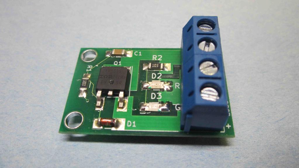
4 Board Assembly All components are installed on the top side of the board which also shows the siklscreen placement of the components. 1. Locate C1 on the board. Tin (wet) ones of the pads. While heating the wetted pad, slide one end of the.1uf capacitor (tan body) into the pad, align the part with the other pads, and allow the solder to melt into it. Solder the remaining pads in place. Check the first pad and touch up if needed. 2. Using the same technique as above, solder the following: R1 10K Resistor Marked as 103 R2 10K Resistor Marked as 103 D1 Zener Diode Observe the polarity (band) on the PCB with the blue band on the diode. 3. Using the same technique as above, solder the following LED's D2 RED LED See notes below for polarity D3 GREEN LED See notes below for polarity Note the BOTTOM of the LED will have a "T" printed on it. The T aligns with the anode and cathode symbols as shown below: LED upside down showing markings 2 of 5 kc9on V4


5 4. Tin (wet) the one of the smaller pads on Q1. Using the same technique as above, slide Q1 into place while aligning the other leg and heatsink. Solder the other leg and heatsink into place. On the bottom side of the board optionally fill the 5 via pads under Q1 with solder. 5. Slide the 2 terminal blocks together to lock in place. Insert and solder terminal blocks P1 and P2. Make sure the wire etrances are pointing away from the PCB. This completes the board assembly procedure. 3 of 5 kc9on V4
 SOURCE terminal on the RPP board. 3.")
6 Board Installation A typical installation is made by interupting the connection directly after the power connector inside a radio. The following procedure shows a typicaly installation inside an HW Cut the power leads directly after the power connector. 2. Connect the positive lead from the power connector to the positive (+) SOURCE terminal on the RPP board. 3. Connect the negative lead from the power connector to the negative (-) SOURCE terminal on the RPP board. 4. Connect the positive lead going to the radio to the positive (+) LOAD terminal on the RPP board. 5. Connect the negative lead going to the radio to the negative (-) LOAD terminal on the RPP board. Alternative connection: The negative leads do not necessairly need to be connected through the RPP board. Only a single negative (-) lead can be connected to the RPP board as long as a single common (AKA ground) connection within the radio exists for the power supply negative, radio negative, and RPP board. Additionally this alternative connection only works when a single device is connected to a power supply. Note the mounting holes have no electrical connection. RPP-SMT installed in an HW-8 RPP Schematic 4 of 5 kc9on V4
7 SPECIFICATIONS: Supply voltage input: Minimum: 4V (Vgsth) Maximum: 50V (Vdss) (See IRF4905 spec sheet for details) Current Load: 4.25A Continous 7A Peak Typical Voltage Drop across RPP 13.4VDC): 1mV@60mA 130mV@820mA 340mV@1.3A 900mV@5.4A for 60seconds FAQs: What do the components do? Q1 is configured to act as a switch, allowing current to pass when properly polarized and the circuit to appear open when reversed. C1 just helps prevent static discharge protection between the gate and drain. R1 and D1 help clamp the voltage between gate and source. In the case of the IRF4905 these 2 parts they are really not needed as long as the power supply remains below 20V (The Vgs max of the transistor). In this case the diode can be omitted and the resistor can be jumpered. When used the resistor is not critical, anything between 10K and 100K will work. The zener diode, however, must be a value between the MOSFETs Vgsth and Vgss maximim. Hey! This MOSFET is rated for 31A, why the above current limits?? First off it's 31A with a maximum power dissipation of 110W at room temperature. Push a bunch of current through it, which causes heat, and that 31A derates to 22A at 212F (100C). Secondly the terminal blocks are rated for 15A maximum. But the PCB itself is the biggest limitation. PCB traces of 1.4mils thick and conductors of 1/2" long by 80 mils wide calculates to about 4.25A of maximum current. Although the traces are duplicated on both sides of the PCB, it might handle up to 7A but we decided to keep the safety margin of 4.25A in place. Adding a heat sink to Q1 along with duplicating the power traces with thick wires could increase the current ratings. The MOSFET was chosen for it's low RdsOn, not it's maximum amperage. 5 of 5 kc9on V4
SMD-Dummy-BNC Assembly Instructions
 This small QRP sized dummyload was designed as a learning tool for SMD soldering by using larger 2512 resistors with only 1 small SOT-23 diode. The 50 ohm load will operate from 500KHz to 30MHz with an
HW-8-TR V3 PARTS LIST
 HW-8-TR V3 PARTS LIST Qty Ref Description Markings 4C2 C3 C4 C5 Capacitor Disc.1ls.1uF 104 1 C1 Capacitor Disc.2ls.1uF 100V 104 1 QSKMOD-C92 Capacitor Electrolytic 1uF 50V 1 QSKMOD Capacitor Mylar.47uF
LED Field Strength Indicator Kit
 LED Field Strength Indicator Kit Description The Field Strength Indicator kit from Qrpkits.com provides a visual way to monitor RF fields through the brightness of an LED. It will respond to RF fields
Xkitz.com XLO-5CP Control Panel for Five Channel Color Light Organ
 Xkitz.com XLO-5CP Control Panel for Five Channel Color Light Organ Rev 1.15 An Optional accessory for the Xkitz XLO-5 or XLO-5DC 5 Channel Color Light Organs Introduction This kit contains all the electronics
SSRP LTC1746 Assembly Manual V0.1 Check the most recent version
 SSRP LTC1746 Assembly Manual V0.1 Check the most recent version http://oscar.dcarr.org/ssrp/hardware/ltc1746/ltc1746.php Introduction This manual details the general assembly process for the SSRP LTC1746
Bill of Materials: PWM Stepper Motor Driver PART NO
 PWM Stepper Motor Driver PART NO. 2183816 Control a stepper motor using this circuit and a servo PWM signal from an R/C controller, arduino, or microcontroller. Onboard circuitry limits winding current,
Pacific Antenna Field Strength Indicator Kit
 Pacific Antenna Field Strength Indicator Kit Description The Field Strength Indicator kit from Pacific Antenna provides a visual way to monitor the presence and relative strength RF fields through the
LITTLE NERD v1.1 Assembly Guide
 last update: 9. 3. 2016 LITTLE NERD v1.1 Assembly Guide bastl instruments.com INTRODUCTION This guide is for building Little Nerd module from Bastl Instruments. It is good to have basic soldering skills
Easy Transmitter. Support ETX_REV5_Manual V2.7 Revised
 Easy Transmitter Introduction The Easy Transmitter kit from qrpkits.com provides a basic, crystal controlled transmitter with VXO tuning to provide a small tuning range around the crystal frequency. It
Bill of Materials: General Purpose Alarm, Pulsed PART NO
 General Purpose Alarm, Pulsed PART NO. 2190207 I hate alarms that sound continuously - unless they are smoke alarms. Smoke alarms should be annoying, but others should not. I wanted an alarm for a function
Assembly Instructions for the 1.5 Watt Amplifier Kit
 Assembly Instructions for the 1.5 Watt Amplifier Kit 1.) All of the small parts are attached to a sheet of paper indicating both their value and id. 2.) Leave the parts affixed to the paper until you are
Assembly instructions for the CS-1 ChemShield
 Page 1 Of 6 Assembly instructions for the CS-1 ChemShield What is S.M.D SMD=Surface mount devices, like all the components does not have leads, but gets soldered onto flat solder pads. The CS-1 assembly
Learn to Solder: Simon Says Stencil Kit Information & Instructions
 Learn to Solder: Simon Says Stencil Kit Information & Instructions This is considered an intermediate kit for people who have soldered through-hole components before and wish to learn how to reflow surface
01. Parts. Blink v1.1. Battery Holder x1. Red LED x1 Green LED x1 Blue LED x1. Resistors x3. Battery x1. Blink PCB x1. Push Button Switchers x3
 Blink L1 L2 L3 01. Parts Battery Holder x1 Red LED x1 Green LED x1 Blue LED x1 Resistors x3 Learn to Solder Kit Battery x1 L1 L2 L3 Blink PCB x1 S3 Push Button Switchers x3 02. Tools RECOMENDED Soldering
Pacific Antenna - Easy TR Switch
 Pacific Antenna - Easy TR Switch Kit Description The Easy TR Switch is an RF sensing switch that can be used to switch an antenna between a receiver and transmitter. It also has a second switched pair
RBS RADIO BATTERY SWITCH CONSTRUCTION MANUAL. RBS Construction Manual Issue 1 Page 1
 RBS RADIO BATTERY SWITCH CONSTRUCTION MANUAL RBS Construction Manual Issue 1 Page 1 CONTENTS 1 Introduction... 4 1.1 RBS features... 4 2 Batteries... 5 3 RBS specifications... 6 4 Circuit Description...
Read This Page First
 Read This Page First If you are reading this you know the manuals are always available at QRPKITS.com. This is version 8.0 of the manual dated 4/27/2016. There is no need to print out the whole assembly
Pacific Antenna Easy SWR Indicator Kit
 Pacific Antenna Easy SWR Indicator Kit Description Monitoring the match of an antenna to your transmitter or adjusting an antenna tuner for best match requires an indicator of the reflected power as an
Arizona ScQRPion QRP Club. Ft Tuthill w DC CW Transceiver for 80m Part 1 of 2. by Dan Tayloe, N7VE. Ft Tuthill Page 1 of 31
 Arizona ScQRPion QRP Club Ft Tuthill 80 2.5w DC CW Transceiver for 80m Part 1 of 2 by Dan Tayloe, N7VE Page 1 of 31 Table of Contents Specifications... 4 Specifications... 4 Receiver... 4 Transmitter...
Pacific Antenna Easy TR Switch
 Pacific Antenna Easy TR Switch Kit Description The Easy TR Switch is an RF sensing circuit with a double pole double throw relay that can be used to automatically switch an antenna between a separate receiver
Lighthouse Beginner s soldering kit
 Lighthouse Beginner s soldering kit Kit contains: 1 x 220 ohm resistor (Red, Red, Black) 1 x 82k ohm resistor (Grey, Red, Orange) 2 x 220k ohm resistors (Red, Red, Yellow) 2 x Diodes 1 x Power switch 1
CW-ADD. Universal CW Adapter for SSB Transceivers. Assembly manual. Last updated: October 1,
 CW-ADD Universal CW Adapter for SSB Transceivers Assembly manual Last updated: October 1, 2017 ea3gcy@gmail.com Updates and news at: www.ea3gcy.com Thanks for building the Universal CW Adapter kit CW-ADD
Assembly Instructions
 Assembly Instructions For the SSQ-2F 3.1 MHz Rife Controller Board Kit v1.41 Manual v1.00 2012 by Ralph Hartwell Spectrotek Services GENERAL ASSEMBLY INSTRUCTIONS Arrange for a clean work surface with
SoftRock v5.0 Builder s Notes. December 12, Building a QSD Kit
 SoftRock v5.0 Builder s Notes December 12, 2005 Building a QSD Kit Be sure to use a grounded tip soldering iron in building the QSD board. The soldering iron needs to have a small tip, (0.05-0.1 inch diameter),
SoftRock v6.0 Builder s Notes. April 6, 2006
 SoftRock v6.0 Builder s Notes April 6, 006 Be sure to use a grounded tip soldering iron in building the v6.0 SoftRock circuit board. The soldering iron needs to have a small tip, (0.05-0. inch diameter),
Elektor Construction Guide TAPIR
 Elektor Construction Guide TAPIR The TAPIR is a three-dimensional assembly. To ensure good access to all soldering points, we recommend assembling the kit exactly according to the described sequence. 1
KASTLE v1.5 - Assembly Guide
 last update: 14. 12. 2017 KASTLE v1.5 - Assembly Guide bastl-instruments.com INTRODUCTION Welcome to the assembly guide for the Kastle kit - mini modular synthesizer. It is suitable for beginners. It is
Firefly Jar Learn to Solder Kit
 Firefly Jar Learn to Solder Kit Parts Tools A. Firefly Jar PCB B. 10mm Flickering LED (White or Yellow) C. Resistor D. Tilt Switch (Black or Green) E. Battery Holder F. Velcro ( Not Pictured) G. Jar (
TKEY-1. CW touch key. (no electromechanical contacts) Assembly manual. Last update: May 1,
 Assembly manual. Last update: May 1,") TKEY-1 CW touch key (no electromechanical contacts) Assembly manual Last update: May 1, 2016 ea3gcy@gmail.com Updates and news at: www.qsl.net/ea3gcy Thanks for constructing the TKEY-1A CW touch key Have
TKEY-1 CW touch key (no electromechanical contacts) Assembly manual Last update: May 1, 2016 ea3gcy@gmail.com Updates and news at: www.qsl.net/ea3gcy Thanks for constructing the TKEY-1A CW touch key Have
SoftRock v6.0 Builder s Notes. May 22, 2006
 SoftRock v6.0 Builder s Notes May 22, 2006 Be sure to use a grounded tip soldering iron in building the v6.0 SoftRock circuit board. The soldering iron needs to have a small tip, (0.05-0.1 inch diameter),
ABC V1.0 ASSEMBLY IMPORTANT!
 ABC V1.0 ASSEMBLY Before starting this kit, prepare the following tools: Soldering iron (15-20W will do), flush cutters, no.2 hex screwdriver or allen key and phillips screwdriver. Also briefly go through
MICROGRANNY v2.1 - Assembly Guide
 last update: 9. 5. 2017 MICROGRANNY v2.1 - Assembly Guide bastl-instruments.com INTRODUCTION Welcome to the assembly guide for the MicroGranny kit. MicroGranny is a monophonic granular sampler by Bastl
Executive Decision Maker Pro Assembly Guide
 Assembly Guide 1 Introduction Congratulations with acquiring your Executive Decision Make Pro. This guide attempts to follow you through the entire assembly process and should give you help to find order
BINARY. Logic functions for analog computation DIY BUILD GUIDE GRAYSCALE.
 BINARY Logic functions for analog computation DIY BUILD GUIDE GRAYSCALE http://grayscale.info BINARY DIY BUILD GUIDE Binary from Grayscale is a 1-bit analog computer for digital logic signals. Patch up
Building the Toothpick Audio CW Filter
 Building the Toothpick Audio CW Filter Introduction The toothpick is a simple variable bandpass audio filter designed to compliment the Splinter QRPp Trans-Receiver. The filter also contains an audio amplifier
BP-1A. Band-Pass variable filter continuous tuning from 3 to 30MHz. For analogue or software-defined receivers (SDR) Assembly manual
 Assembly manual") BP-1A Band-Pass variable filter continuous tuning from 3 to 30MHz. For analogue or software-defined receivers (SDR) Assembly manual Last updated: December 1, 2017 ea3gcy@gmail.com Updates and news at:
BP-1A Band-Pass variable filter continuous tuning from 3 to 30MHz. For analogue or software-defined receivers (SDR) Assembly manual Last updated: December 1, 2017 ea3gcy@gmail.com Updates and news at:
Solder is a metallic glue that holds the parts together and forms a connection that allows electrical current to flow.
 Proper Soldering & Desoldering High Performance Ultrasonic Range Finders Techniques of a MaxBotix Sensor Materials Needed for Soldering Goggles Hands-free clamp Wire stripper Soldering iron with stand
Building The DC Beeper from Jackson Harbor Press A Morse code voltmeter / DC switch
 Building The DC Beeper and from Jackson Harbor Press Operating A Morse code voltmeter / DC switch The DC Beeper kit is a combination of a Morse code voltmeter with 20 mv resolution and a DC switch. The
Warm Tube Clock. Before we start, please make sure that you have all required parts that come for the main board :
 Warm Tube Clock Assembly Instructions for the main board Introduction Congratulations on your purchase of OSH Nixie Tube Clock. In this document you will see all steps you need to follow in order to successfully
SDR Cube Transceiver Online Assembly Guide
 SDR Cube Transceiver Online Assembly Guide Detailed construction notes for building and testing each of the SDR Cube kit modules Home Bill of Materials I/O Board Controls Board DSP Board Softrock SR-Base
Bi-Directional DC Motor Speed Controller 5-32Vdc (3166v2)
") General Guidelines for Electronic Kits and Assembled Modules Thank you for choosing one of our products. Please take some time to carefully read the important information below concerning use of this product.
General Guidelines for Electronic Kits and Assembled Modules Thank you for choosing one of our products. Please take some time to carefully read the important information below concerning use of this product.
DIODE / TRANSISTOR TESTER KIT
 DIODE / TRANSISTOR TESTER KIT MODEL DT-100K Assembly and Instruction Manual Elenco Electronics, Inc. Copyright 1988 Elenco Electronics, Inc. Revised 2002 REV-K 753110 DT-100 PARTS LIST If you are a student,
QRPGuys Iambic Mini Paddle w/base
 QRPGuys Iambic Mini Paddle w/base First, familiarize yourself with the parts and check for all the components. If a part is missing, please contact us and we will send one. You must use qrpguys.parts@gmail.com
Circuit Board Assembly Instructions for Babuinobot 1.0
 Circuit Board Assembly Instructions for Babuinobot 1.0 Brett Nelson January 2010 1 Features Sensor4 input Sensor3 input Sensor2 input 5v power bus Sensor1 input Do not exceed 5v Ground power bus Programming
DuoDrive Nixie Bargraph Kit
 Assembly Instructions And User Guide Nixie Bargraph Kit - 1 - REVISION HISTORY Issue Date Reason for Issue Number 1 12 December 2017 New document - 2 - 1. INTRODUCTION 1.1 About Nixie Bargraph Driver IN-9
EE 1202 Labs: Ground Rules
 EE 1202 Labs: Ground Rules There are eight lab exercises that you will do as a part of EE 1202. The EE 1202 lab is ECSS 4.622, on the third floor of the ECSS building. Lab exercises will be done by teams
TS500 Assembly guide. Soldering. TS500 Assembly guide Main PCB 1. Diodes. Document revision 1.2 Last modification : 17/12/16
 TS500 Assembly guide Safety warning The kits are main powered and use potentially lethal voltages. Under no circumstance should someone undertake the realisation of a kit unless he has full knowledge about
Manual Version July 2007
 Manual Version 1.2 - July 2007 Page 1 Table of Contents Section1: M3 Phono Board Build...3 Phono Board Parts List...3 Preparation...4 Fitting the Valve Bases...6 Installing the Resistors...7 Starting the
12V Dimmer Kit, version 2
 12V Dimmer Kit, version 2 User Manual Description The 12V Dimmer Kit V2 is an especially efficient PWM (pulse-width modulation) controller for 12V loads up to 60 watts. It features a single dial control
Electrical Workshop. Module 6: Soldering Techniques. Academic Services Unit PREPARED BY. August 2012
 Electrical Workshop PREPARED BY Academic Services Unit August 2012 Applied Technology High Schools, 2012 Module Objectives Upon successful completion of this module, students should be able to: 1. Identify
Pacific Antenna Easy Transmitter Kit
 Pacific Antenna Easy Transmitter Kit Introduction The Easy Transmitter kit from qrpkits.com provides a crystal controlled transmitter with VXO tuning. The circuit consists of a N3904 based crystal oscillator
Mounting Approaches for RF Products Using the Package Type
 Application Note: APPNOTE-012 Rev. A APPLICATION NOTE Mounting Approaches for RF Products Using the 780019 Package Type Introduction The objective of this application note is to provide users of Cree RF
QRPGuys SMT Digital Dial/Frequency Counter
 QRPGuys SMT Digital Dial/Frequency Counter First, familiarize yourself with the parts and check for all the components. If a part is missing, please contact us and we will send one. You must use qrpguys.parts@gmail.com
Gat ew ay T o S pace AS EN / AS TR Class # 07. Colorado S pace Grant Consortium
 Gat ew ay T o S pace AS EN / AS TR 2500 Class # 07 Colorado S pace Grant Consortium One Minute Reports: - Can we have two data loggers? - Do you provide us with cameras? {Hardware Checkout after proposal}
Building the Sawdust Regenerative Receiver
 Building the Sawdust Regenerative Receiver Introduction The Sawdust is a super regenerative receiver using the basic Armstrong design architecture. The receiver uses one toroidal transformer to provide
How to solder SMD component on Awesome PCB or any other kind of PCB.
 How to solder SMD component on Awesome PCB or any other kind of PCB. Step by step tutorial, with no steps to skip. Step 1 - What do we need? Step 2 - Fixing PCB Step 3 - Preparing for soldering Step 4
Guitarpedalkits.com Overdrive Pedal Build Instructions
 Page 1 Guitarpedalkits.com Overdrive Pedal Build Instructions Follow the instructions in this guide to build your very own DIY overdrive pedal from GuitarPedalKits.com. If you re a first time builder,
Penrose Quantizer Assembly Guide
 Penrose Quantizer Assembly Guide Schematic and BOM The schematic can be found here: www.sonic-potions.com/public/penrosequantizerschematic.pdf The BOM is available at google docs: Link to BOM Prepare the
AC/DC POWER SUPPLY KIT
 AC/DC POWER SUPPLY KIT MODEL K-11 Assembly and Instruction Manual ELENCO Copyright 2016, 1989 by ELENCO All rights reserved. Revised 2016 REV-O 753211 No part of this book shall be reproduced by any means;
Custom Front Panel Upgrade Instructions
 Custom Front Panel Upgrade Instructions Here are the directions for upgrading your SP-II to an SP-IIB, with a custom blackanodized front panel and engraved lettering. There are only forty SP-IIB s in existence
Read This Page First
 Read This Page First If you are reading this you know the manuals are always available at QRPKITS.com. If you have questions contact qrpkits.com@gmail.com There is no need to print out the whole assembly
The Infinity Bug. This is an amazing project... Order kit Fully assembled version $199 Order Infinity Bug
 The Infinity Bug This is an amazing project... us$55.00 plus $6.50 post Order kit Fully assembled version $199 Order Infinity Bug The INFINITY BUG is connected across the phone-line of a distant phone
Cricket 80a Assembly Manual v Copyright David Cripe NM0S The 4 State QRP Group
 Cricket 80a Assembly Manual v. 1.0 Copyright 2017 David Cripe NM0S The 4 State QRP Group Introduction Thank you for purchasing a CRICKET 80a Transceiver. We hope you will enjoy building it and find it
FROM SCHEMATIC TO VEROBOARD
 FROM SCHEMATIC TO VEROBOARD The circuit of a bench amplifier utilising a LM386 linear (integrated circuit) IC and a few other components is used for this tutorial. The schematic is shown below: First a
KLIK v1.0 - Assembly Guide
 last update: 12. 7. 2017 KLIK v1.0 - Assembly Guide bastl-instruments.com INTRODUCTION Welcome to the assembly guide for the KLIK by BASTL INSTRUMENTS. Klik is a synchronisation device that enables you
Instructions for Building the Pulsed Width Modulation Circuit. MC-12 (DC Motor Controller or PWM) From Electronic Light Inc. (revised kit 5/08)
 From Electronic Light Inc. (revised kit 5/08)") Instructions for Building the Pulsed Width Modulation Circuit MC-12 (DC Motor Controller or PWM) From Electronic Light Inc. (revised kit 5/08) Using this circuit for a pulsed DC current to your cell. Do
Instructions for Building the Pulsed Width Modulation Circuit MC-12 (DC Motor Controller or PWM) From Electronic Light Inc. (revised kit 5/08) Using this circuit for a pulsed DC current to your cell. Do
FM Wireless Microphone Kit Instructions for Assembly Page 1 of 5
 Instructions for Assembly Page 1 of 5 1. Find Resistor R1. Remove any tape that may be attached to the leads. Bend the leads as needed to insert Resistor R1 into the printed circuit board in the holes
Building the Sawdust Regenerative Receiver
 Building the Sawdust Regenerative Receiver Introduction The Sawdust is a super regenerative receiver using the basic Armstrong design architecture. The receiver uses one toroidal transformer to provide
Starving Student II. Starving Student II. SS2 guide. Written By: 6L guides.diyaudio.com/ Page 1 of 24
 SS2 guide Written By: 6L6 2019 guides.diyaudio.com/ Page 1 of 24 INTRODUCTION This is a build guide for the hybrid headphone/pre-amplifier. You can buy a kit at the SSII product listing on the diyaudio
Instructions for Building the Pulsed Width Modulation Circuit. MC-12 (DC Motor Controller or PWM) From Electronic Light Inc. (revised kit 8/08)
 From Electronic Light Inc. (revised kit 8/08)") Instructions for Building the Pulsed Width Modulation Circuit MC-12 (DC Motor Controller or PWM) From Electronic Light Inc. (revised kit 8/08) Using this circuit for a pulsed DC current to your cell. Do
Instructions for Building the Pulsed Width Modulation Circuit MC-12 (DC Motor Controller or PWM) From Electronic Light Inc. (revised kit 8/08) Using this circuit for a pulsed DC current to your cell. Do
V6.2 SoftRock Lite Builder s Notes. November 17, 2006
 V6.2 SoftRock Lite Builder s Notes November 17, 2006 Be sure to use a grounded tip soldering iron in building the v6.2 SoftRock circuit board. The soldering iron needs to have a small tip, (0.05-0.1 inch
HT-1A Dual Band CW QRP Transceiver. Kit Building Instructions
 HT-A Dual Band CW QRP Transceiver Kit Building Instructions Rev B, July 8, 08 Designed by BD4RG Exclusively distributed by CRKITS.COM and its worldwide distributors Join the group http://groups.io/g/crkits
TekBot Remote Control Receiver Board Construction
 TekBot Remote Control Receiver Board Construction Purpose This tutorial illustrates the procedure for construction of the Receiver board for the TekBot. A Guide to Soldering Many of you have soldered once
N3ZI Kits General Coverage Receiver, Assembly & Operations Manual (For Jun 2011 PCB ) Version 3.33, Jan 2012
 Version 3.33, Jan 2012") N3ZI Kits General Coverage Receiver, Assembly & Operations Manual (For Jun 2011 PCB ) Version 3.33, Jan 2012 Thank you for purchasing my general coverage receiver kit. You can use the photo above as a
N3ZI Kits General Coverage Receiver, Assembly & Operations Manual (For Jun 2011 PCB ) Version 3.33, Jan 2012 Thank you for purchasing my general coverage receiver kit. You can use the photo above as a
Physics of Music Projects Final Report
 Physics of Music Projects Final Report Kyle Kleyweg Prof. Steven Errede PHYS498 POM May 12, 2011 1 Abstract The following project was begun in the spring of 2011 in an attempt to create plasma speakers
SMT in Practice. Special Seminar III. Dr. Peter W. Pachowicz Department of Electrical and Computer Engineering Volgenau School of Engineering
 Special Seminar III SMT in Practice Dr. Peter W. Pachowicz Department of Electrical and Computer Engineering Volgenau School of Engineering This seminar is dedicated to students taking senior design project
Eurorack DIY Kit Instructions. All Thonk kits are sold under our standard Terms and Conditions -
 MA VCA OVERVIEW For the most recent version of this document please visit http://thonk.co.uk/documents/ma/ For all technical support please visit http://bit.ly/1tl78e0 on Muffwiggler. All Thonk kits are
DIODE / TRANSISTOR TESTER KIT
 DIODE / TRANSISTOR TESTER KIT MODEL DT-100K 99 Washington Street Melrose, MA 02176 Phone 781-665-1400 Toll Free 1-800-517-8431 Visit us at www.testequipmentdepot.com Assembly and Instruction Manual Elenco
NERVE TESTER KIT MODEL K-20. Assembly and Instruction Manual. Elenco Electronics, Inc.
 NERVE TESTER KIT MODEL K-20 Assembly and Instruction Manual Elenco Electronics, Inc. Copyright 1989 Elenco Electronics, Inc. Revised 2002 REV-E 753220 PARTS LIST If you are a student, and any parts are
Read This Page First
 Pacific Antenna 0 Watt HF Amplifier Kit Manual This is Version 5.5 dated 060505 Read This Page First If you are reading this you know the manuals are always available at QRPKITS.com. If you have questions
MP573 Assembly guide. Soldering. MP573 Assembly guide PCB split PCB split. Document revision 2.2 Last modification : 22/08/17
 MP573 Assembly guide Safety warning The kits are main powered and use potentially lethal voltages. Under no circumstance should someone undertake the realisation of a kit unless he has full knowledge about
THE AGGRESSOR (K-995)
") THE AGGRESSOR (K-99) TONE VOLUME DISTORTION MID-SHIFT SWITCH LED The Aggressor Distortion Pedal Modkitsdiy.com 9 VDC CENTER (-) ADAPTER TO AMP IN FROM GUITAR OUT Unplug when not in use to save battery
THE AGGRESSOR (K-99) TONE VOLUME DISTORTION MID-SHIFT SWITCH LED The Aggressor Distortion Pedal Modkitsdiy.com 9 VDC CENTER (-) ADAPTER TO AMP IN FROM GUITAR OUT Unplug when not in use to save battery
Workshop Part Identification Lecture N I A G A R A C O L L E G E T E C H N O L O G Y D E P T.
 Workshop Part Identification Lecture N I A G A R A C O L L E G E T E C H N O L O G Y D E P T. Identifying Resistors Resistors can be either fixed or variable. The variable kind are called potentiometers
5W Mono Amplifier Kit
 5W Mono Amplifier Kit Kit Construction Before you start assembling your kit there are a couple of important things you must do. FIRST read through these instructions entirely before you start construction
Assembly Instructions for the FRB FET FM 70 Watt Amp
 Assembly Instructions for the FRB FET FM 70 Watt Amp 1.) Orient the circuit board with the diagram 2.) Use a narrow chisel tip 25-30 watt soldering iron for assembly 3.) All the small parts are taped onto
QUASAR ELECTRONICS KIT No DRILL SPEED CONTROLLER
 QUASAR ELECTRONICS KIT No. 1074 DRILL SPEED CONTROLLER General Description If you work with an electric drill and unless you are lucky enough to own one of the most sophisticated models with speed control,
ScaleRCHelis.com V Light Controller Kit
 Thank you for purchasing the ScaleRCHelis.com V1.1 450 Light Controller Kit. This is something you can build in under a hour with some simple soldering equipment. Your kit will include all the parts necessary
QLG1 GPS Receiver kit
 QLG1 GPS Receiver kit 1. Introduction Thank you for purchasing the QRP Labs QLG1 GPS Receiver kit. This kit will provide a highly sensitive, highly accurate GPS receiver module, using the popular MediaTek
Assembly Instructions
 Assembly Instructions for the PA3 v2.0 Amplifier Kit PA3 Amplifier shown mounted on HS2 Heat Sink (The HS2 shown here is not included with this kit.) 27 February 2016 2013-2016 by Ralph Hartwell Spectrotek
Stand Alone VXO (SAVXO) Assembly Manual Manual Version 1.0B_
 Assembly Manual Manual Version 1.0B_") Stand Alone VXO (SAVXO) Assembly Manual Manual Version.0B_0-6-0 Designed by: Jim Kortge, K8IQY Kitted & Sold by: 4 State QRP Group Copyright: 0 Forward Thank you for purchasing a 4 State QRP Group Stand
Stand Alone VXO (SAVXO) Assembly Manual Manual Version.0B_0-6-0 Designed by: Jim Kortge, K8IQY Kitted & Sold by: 4 State QRP Group Copyright: 0 Forward Thank you for purchasing a 4 State QRP Group Stand
Pacific Antenna Code Practice Oscillator Kit
 Pacific Antenna Code Practice Oscillator Kit This kit is offered to initiate the first time builder in the various techniques of mechanical and electronic kit construction. At the end of the approximately
Installing the Onyx Heated Bed
 Installing the Onyx Heated Bed This short supplement will guide you through replacing the Phebe I heated bed on your Rostock MAX with the new Onyx heated bed. Your Onyx upgrade kit should include the following
THE RING RESONATOR (K-975)
") THE RING RESONATOR (K-975) OUTPUT BOOST The Ring Resonator An Octave Up Fuzz Modkitsdiy.com 9 VDC CENTER (-) ADAPTER TO AMP IN FROM GUITAR OUT Unplug when not in use to save battery life. Use these instructions
THE RING RESONATOR (K-975) OUTPUT BOOST The Ring Resonator An Octave Up Fuzz Modkitsdiy.com 9 VDC CENTER (-) ADAPTER TO AMP IN FROM GUITAR OUT Unplug when not in use to save battery life. Use these instructions
Assembly Instructions for B7971 Smart Socket
 Assembly Instructions for B7971 Smart Socket Identification and installation of the resistors, Fig1 Segment 1,R1, 22k Segment 4, R4, 22k Segment 2, R2, 27k Segment 3, R3, 27k Segment 5, R5, 27k Segment
Electronics Merit Badge Class 4. 12/30/2010 Electronics Merit Badge Class 4 1
 Electronics Merit Badge Class 4 12/30/2010 Electronics Merit Badge Class 4 1 Soldering Safety Note: A Soldering Iron gets hotter than 374 F. Do not touch the soldering iron s metal parts or you will receive
EZ1290 Assembly Guide
 EZ190 Assembly Guide Capacitors This picture shows the different types of capacitors used and how they are symbolized and mounted on the PCB. Don t mess this up or bad things will happen!!! Electrolytic
Learn to solder electronics with the Maker
 Learn to solder electronics with the Maker Shed Solder Badge! How to assemble the Maker Shed Badge kit. Written By: Alexander ifixit CC BY-NC-SA www.ifixit.com Page 1 of 19 INTRODUCTION The Maker Shed
MEGAbitty Micro Line Sensor Board Assembly Instructions 11/15/2003
 1 Board Preparation U1 & U2 are mounted upside down, protruding through the board. That is, when the board is viewed from the top, the lenses should point down. Holes for U1 & U2 need to be cut out. Use
VC Divider Assembly manual
 1 VC Divider Assembly manual Thank you for your purchase of the SSSR Labs VC Divider DIY Kit! This manual will help you assemble the VC Divider quickly and easily. Follow the instructions! As you may know,
BrewsBySmith.com STC DIY Kit
 BrewsBySmith.com STC-1000 + DIY Kit Contact Information: Greg Smith www.brewsbysmith.com greg@boostbysmith.com I. Hardware Included: STC-1000 flashed with latest software (v1.06 currently) (if purchased)