Instruction Manual. CT101 line stage / linear preamplifier module
|
|
|
- Harvey Ball
- 5 years ago
- Views:
Transcription

1 CT0 line stage / linear preamplifier module
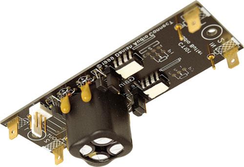
2 CT0 CONTENT UNPACKG channel line stage / linear preamplifier module Unpacking Connections Definitions Power supply Signal input Signal output Volume control setting Power supply Volume control setting Mounting / assembling Other information Headphones Balanced preamplifier channel A/V audio DC offset Hints Caution Please make sure to read through all of this Instruction Manual before connecting your CT0. Side view X SMD components Do not bend the CT0 PCB. Bending it may easily damage the SMD components on the rear side. Thank you for purchasing this Danish Audio ConnecT product. CT0 is a readymade channel linear audio preamplifier module built on a compact PCB. CT0 is specifically designed for using with a DACT stepped audio attenuator as volume control. Connecting CT0 to input/output sockets and an external power supply will provide you with a high quality, nononsense, active preamplifier. Your CT0 purchase includes pc. CT0 channel linear preamplifier module mounting set consisting of pcs. M stainless steel screws pcs. M stainless steel nuts pcs. M brass spacers 4 pcs. stainless steel washers pcs. power supply connectors including wires pcs. jumpers for using CT0 with one power supply pc. instruction manual We recommend that you make sure to keep all of the above items after unpacking your CT0, as everything will prove useful to you when mounting and connecting your CT0. CONNECTIONS Definitions Marking refers to the text printed on the CT0 Printed Circuit Board: Marking Definition Signal input, channel Signal input, channel Signal output, channel Signal output, channel P, Attenuator, channel P, Attenuator, channel / Power supply to one or both of the way connectors Please also refer to Fig.. Copyright 00, Danish Audio ConnecT A/S, Denmark. All rights reserved. Revised 8 August 00
3 CT0 channel line stage / linear preamplifier module x power supply connectors Dual or single power supply 'programming' PCB holes for connecting the volume control 999 Danish Audio ConnecT Channel Channel CT0 P P x settings SIGNAL Signal GND SIGNAL Signal GND x signal input connectors x signal output connectors Fig.. CT0 connections Power supply CT0 is designed for using with either one / power supply common for both channels, or with a / power supply for each channel. The two channels of CT0 are completely separated on the PC Board. Therefore, when a power supply for each channel is used, the operation is true dualmono. The power supplies must be connected to the way square pin headers as shown in fig. and fig. (exact connector dimensions specified in fig. of the CT0 Datasheet). The colour codes (RED, BLACK, BLUE) in fig. refer to the colours of the wires attached to the two separate power supply connectors, which are included when purchasing a CT0. For more details please refer to the POWER SUPPLY chapter on the following pages. Signal input The input terminals are marked and on the CT0 PCB, and consists each of a round pin terminal and a flat tab terminal (specified in fig. of the CT0 Datasheet). Generally, we recommend connecting the inputs with screened cables. The longer the input cables are, the more important is the screening. If the distance between the input sockets and the CT0 PCB is short, nonscreened cables may be used. For nonscreened signal cables, we recommend twisting the signal and the signal ground wires. For each channel, the cable outer conductor (screen braid/foil) must be soldered to the flat tab connector (~ spade terminal ), and the cable centre conductor (core) must be soldered to the round pin terminal. See fig.. Copyright 00, Danish Audio ConnecT A/S, Denmark. All rights reserved. Revised 8 August 00

4 CT0 channel line stage / linear preamplifier module Positive supply voltage RED 0 Zero supply voltage BLACK Negative supply voltage BLUE Fig.. CT0 power supply connections Signal output The output terminals are marked and on the CT0 PCB, and consist each of a round pin terminal and a flat tab terminal (specified in fig. of the CT0 Datasheet). Generally, we recommend connecting the inputs with screened cables. The longer the input cables are, the more important is the screening. If the distance between the input sockets and the CT0 PCB is short, nonscreened cables may be used. For nonscreened signal cables, we recommend twisting the signal and the signal ground wires. For each channel, the cable outer conductor (screen braid/foil) must be soldered to the flat tab connector (~ spade terminal ), and the cable centre conductor (core) must be soldered to the round pin terminal. See fig.. Volume control The CT0 PCB features holes and connections for a volume control for each of the two channels, marked P and P. See fig.. The layout is made, so either a DACT stereo CT or a DACT stereo CT stepped attenuator will fit directly. For more details please refer to the VOLUME CONTROL chapter on the following pages. setting The gain of CT0 can easily be set at either 0dB ( buffermode ), db or db. Please see fig.. For more details please refer to the GA SETTG chapter on the following pages. Flat tab connector Inner cable conductor Outer cable conductor (screen) Outer cable insulation Round pin terminal Insulation between cable inner and outer conductors CT0 PCB Two solder joints Fig.. CT0 audio signal input/output connections Copyright 00, Danish Audio ConnecT A/S, Denmark. All rights reserved. Revised 8 August 00
5 CT0 channel line stage / linear preamplifier module POWER SUPPLY Requirements CT0 is delivered without power supply in order to let the user decide for and experiment with his own power supply design. For information about available power supplies from DACT, please visit. CT0 requires a / DC power supply to operate. Maximum supply voltages and recommended supply voltage are specified in Table of the CT0 Datasheet. For typical applications, where CT0 is used to drive loads of 5kOhm or greater, the recommend supply voltage is between /7VDC and /5VDC. If CT0 is used to drive loads with lower impedance (for instance headphones), it is advised to limit the supply voltage to between /7VDC and /4VDC. Otherwise, the output devices of CT0 may become overheated. Under typical use, driving a 5kOhm or greater load, CT0 draws less than ma per channel. Driving lower impedances will increase the supply current. Please make sure to be very careful about connecting the power supply correctly. Connecting the power supply An easy and convenient way to connect the power supply is to use one or both of the way connectors, which are included when purchasing a CT0, see fig. 4. Each of them has three wires attached, and they fit the two way pin connectors on the CT0 PCB (shown in fig. ). Positive and negative supply connections are printed on the PCB as and. The red wire must be connected to the positive supply voltage, the blue wire to the negative supply voltage, and the black wire to zero supply voltage. Make sure to connect the power supply polarity correctly. Wrong polarity may destroy CT0 and connected equipment. See also the CAUTION paragraph on the last page. Using an existing power supply One possibility of powering CT0 is from existing audio equipment, like power amplifiers, CDplayers, etc. This is often possible because CT0 requires only little supply current, and because it accepts a wide supply voltage range. Especially when building CT0 into existing equipment, this way of powering it is an option. Before experimenting with readymade audio equipment, please observe that the warranty of the equipment will usually no longer be valid. We recommend that only trained technicians make this kind of surgery. Audio power supply Although CT0 has two voltage regulators for each channel builtin, it is recommend paying attention to the quality of the external power supply. In spite of the builtin voltage regulators, the quality of the external power supply has significant influence on the sound quality of CT0. In our view, a good audio supply for instance features: ability to deliver current pulses with high speed low output resistance far beyond the audio frequency range low noise high ripple suppression Due to the low power consumption of CT0, battery operation is a possibility. Sound testing of CT0 operated by batteries was including in the design phase, and the results proved excellent. Either rechargeable or nonrechargeable batteries may be used. For most types of power supplies, including batteries, we recommend adding some high quality reservoir electrolytic capacitors. It is important that the reservoir capacitors have low ESR, also at high frequencies. Some electrolytic capacitors are specially optimized for higher frequencies, and have ESR specified at 00kHz. We recommend using these types, for instance with capacitance values of,00uf each. The reservoir capacitors should be mounted on the supply lines, as close to CT0 as possible, so only short wires are required. A simplified schematic is shown in fig. 5. Examples of suited reservoir capacitors are RS Components, part no. 949 Farnell, part no Fig. 4. Power supply cables included with CT0 Copyright 00, Danish Audio ConnecT A/S, Denmark. All rights reserved. Revised 8 August 00 4
6 CT0 channel line stage / linear preamplifier module supply voltage 0 0 supply voltage supply voltage Fig. 5. Connecting low impedance power supply reservoir capacitors to CT0 Dual mono (dual power supply) For optimal performance (especially benefiting channel separation), we recommend using a separate power supply for each CT0 channel (dual mono). Both power supplies should be identical and meet the abovementioned requirements. When purchasing a CT0, the package includes pcs jumpers. In case a / power supply is used for each channel, the three jumpers are not used. In case one power supply is used common for both channels, the three jumpers must be mounted on the front side, and soldered in both ends to the backside of the CT0 PCB. See fig.. If a common power supply is used, it may be connected to the way connector of either channel or channel. WARNG! If the CT0 is power supplied incorrectly with only a positive or only a negative supplyhalf connected, a DC voltage of several Volts may occur on the output terminals and. See also the CAUTION chapter on the last page of this manual. VOLUME CONTROL 999 Danish Audio ConnecT CT0 P P Using one power supply for each channel: The jumpers are not mounted or Fig.. CT0 jumpers for using one or two / power supplies Using one common power supply for both channels: The jumpers are mounted Principally CT0 can be used with any volume control. However, we recommend using only highgrade volume controls. Only the best volume controls will not influence the sound quality of CT0. Especially, we recommend using a DACT stepped audio attenuator with CT0. The CT0 PCB layout makes it possible to fit either a DACT CT stereo or a DACT CT stereo attenuator just by soldering connections on the backside of the PCB. The best way is to solder the volume control directly into the CT0 PCB, obtaining the shortest possible signal path and the best sound. If this is not possible, DACT offers a connection kit that does not require soldering on the attenuator. The connection kit includes x 0cm ( x ) wires. For longer distances, using shielded wires is recommended. Copyright 00, Danish Audio ConnecT A/S, Denmark. All rights reserved. Revised 8 August 00 5
7 CT0 channel line stage / linear preamplifier module Instead of mounting the volume control apart from CT0, a better solution is to fit both together inside the enclosure, and extend the volume control s shaft. DACT offers shaft extension kits for attenuator shaft extension purposes. Make sure always to attach the volume control to the equipment enclosure, to a bracket, or similar. The volume control SHOULD NOT be fastened only by soldering it to the CT0 PCB. Volume controls are available with many different resistances. DACT offers stepped attenuators in 0, 0, 50, 00, 50 and 500kOhm. It is our experience that the lower resistance volume controls sound better than high resistance volume controls when used with CT0. Therefore, we normally recommend using a 0kOhm attenuator with CT0 There is one more concern when deciding which attenuator resistance to use for CT0: The attenuator is connected directly across the audio signal input. Therefore, the attenuator resistance determines the input resistance of the complete unit So for instance a 0kOhm attenuator will fix the CT0 input resistance at 0kOhm. When using a DACT attenuator with CT0, the attenuator must be soldered to the CT0 PCB in the right way. Looking at CT0 with the audio input connectors pointing to the left, and with the component side upwards, the DACT attenuator must be mounted so the attenuator shaft points towards you. See also fig. 0. If a metal enclosure is used, usually the attenuator will be fastened directly to a part of the enclosure, so the attenuator clickhouse is connected to chassis ground (fig. 0). In case the attenuator clickhouse is not connected to chassis ground when mounted, there should be made a separate connection. See also the attenuator pages. In certain cases, it is not required to use a volume control with CT0. If there is no volume control connected to CT0, a jumper must be mounted in each CT0 channel, see fig. 7. In this way, the input resistance is 00Mohm. However, usually a 00Mohm input resistance is not recommendable for audio applications. Therefore, two resistors may be added to reduce the input resistance. See fig. 8. For instance, two high quality 0kOhm resistors may be added (one per channel) to set the input resistance at 0kOhm. 999 Danish Audio ConnecT CT0 P P Fig. 7. Using CT0 without volume control 999 Danish Audio ConnecT CT0 P P Resistors (one per channel) may be connected either across the input terminals or between the volume control points '' and ''. Jumper connecting '' with '' Jumper connecting '' with '' Fig. 8. Using CT0 without volume control but with resistors controlling the input resistance GA SETTG CT0 offers gain settings of 0dB, db or db. 0dB gain setting is referred to as buffer mode. The gain is set individually for the two channels, but usually the gain is set at the same level. setting is made without soldering or using any tools. The gain setting jumpers may be removed or repositioned by hand. Just remove it by pulling it away from the PCB. See fig. 9 for guidance. It is recommended to choose the lowest usable gain setting, as the CT0 specifications at lower gain are slightly better than at the higher gain settings. Copyright 00, Danish Audio ConnecT A/S, Denmark. All rights reserved. Revised 8 August 00
8 CT0 channel line stage / linear preamplifier module 999 Danish Audio ConnecT CT0 P P Fig. 9. CT0 gain setting 0dB gain setting db gain setting db gain setting MOUNTG / ASSEMBLG Mounting hardware To protect CT0 against dust and larger particles, it should always be built into an enclosure. When unpacking CT0, it is mounted in a plastic cover that protects it during shipping. Loosen the two nuts and extract CT0 from the plastic cover. In most cases, the screws, nuts, washers and spacers can be used again for mounting CT0 in its final enclosure. We recommend using the supplied mounting hardware, as all the parts are made of audio grade materials. The mounting hardware supplied by DACT contains neither magnetic materials nor plastics. The easiest way to mount CT0 is by using the two holes in the PCB. When mounting CT0, make sure to keep the PCB traces and solder joints on the back side at a safe distance from electrically conducting materials, in order to avoid shortcircuiting. Building CT0 into existing equipment One possibility is to build CT0 into the enclosure of existing audio equipment, like preamplifiers, CDplayers, etc. This is often possible because CT0 requires only little space, and could possibly be supplied from the existing power supply in the host equipment. Before experimenting with readymade audio equipment, please observe that the warranty of the equipment will usually no longer be valid. We recommend that only trained technicians make this kind of surgery. Copyright 00, Danish Audio ConnecT A/S, Denmark. All rights reserved. Revised 8 August 00 7
9 CT0 channel line stage / linear preamplifier module Chassis ground connection Capacitor reservoir using 4 pcs.,00uf capacitors / DC power supply connections, separate Audio signal for each channel Audio signal input output Connector body isolated from enclosure on both sides,00uf / 5V,00uF / 5V,00uF / 5V,00uF / 5V Cable outer conductor (screen) connections 999 Danish Audio ConnecT CT0 P P Attenuator Cable centre conductor connections Stainless steel screws, washers, nuts and spacers included with CT0 Metal enclosure Attenuator clickhouse CT0 PCB Fig. 0. CT0based preamplifier in metal enclosure Materials considerations DACT believes that magnetic materials and certain plastic materials should not be used for any parts of audio electronics equipment. Magnetic materials are associated with hysteresis losses when exposed to varying electrical/magnetic fields. Plastics are associated with dielectric losses when exposed to varying electrical fields, although some plastics do have very low losses. Both phenomena introduce nonlinear distortion, which disturbs lowdistortion highend audio equipment. Some times plastic enclosures are preferred because of their electrical nonconducting properties. In that case, we recommend using a plastic type with low dielectric loss, like for instance Teflon, polystyrene and polypropylene. Otherwise, we recommend using an enclosure made of a nonmagnetic metal. Easily and cheaply available are enclosures made of aluminium, but also copper and brass are suited materials. Metal enclosures are usually grounded and they reduce electrical fields radiated into the audio electronics, thereby reducing audible noise. Mounting CT0 in a metal enclosure A very typical way to mount CT0 is in a separate metal enclosure. As an example see fig. 0. For nonbalanced audio equipment it is very common to use RCA sockets for audio signal input/output. To avoid hum, make sure that the body (signal GND) of the RCA sockets do not make electrical contact with the metal enclosure. Instead, as shown, make a GND connection from one of the audio input signal grounds to the chassis. Copyright 00, Danish Audio ConnecT A/S, Denmark. All rights reserved. Revised 8 August 00 8
10 CT0 channel line stage / linear preamplifier module OTHER FORMATION Headphones Headphones may be connected directly to the output sockets of CT0, at and. As headphones usually have lower impedance than 5kOhm, the supply voltage for CT0 should be limited to no more than / 4VDC. See also the POWER SUPPLY chapter in this manual. The best results may be obtained using headphones with at least 00ohm resistance. Make sure to connect the phases correctly. WARNG! Avoid playing with the headphones at so loud volumes, that your hearing is permanently affected. Balanced preamplifier CT0 may be used for balanced audio signals. If so, one balanced audio channel requires both channels of a CT0. The positive (noninverted) signal is connected to one channel and the negative (inverted) signal is connected to the other channel. If a balanced stereo preamplifier is required, two CT0s have to be used, one for each channel. As volume control, we recommend using a 4deck DACT stepped attenuator. If the two CT0s are mounted behind each other, the 4deck attenuator will fit directly into both PCBs. For more information we recommend reading the application note on using CT0 to build a multichannel active preamplifier. channel A/V audio CT0 may be used for channel A/V audio signals. Then three CT0s have to be used, for instance one for the front channels, one for the rear channels and on for the center and the sub channels. As volume control, we recommend using a deck DACT stepped attenuator. If the three CT0s are mounted behind each other, the deck attenuator will fit directly into all three PCBs. For more information we recommend reading the application note on using CT0 to build a multichannel active preamplifier. DC offset All DCcoupled equipment always has a small DC offset at the output. CT0 typically has a DC offset around mv at 0dB gain setting. This level is usually not a problem. If a DCcoupled amplifier follows CT0, it must be evaluated if the DC offset level at all points in the chain of audio equipment is at acceptable levels. Especially the DC level across the loudspeaker terminals is critical. To remove the DC offsets, audio grade coupling capacitors may be added. Hints. Power on / of must be switched with a doublepole switch to ensure that both the positive and the negative supply voltage are switched simultaneously.. DCcoupled power amplifiers represent a potential risk for loudspeakers. Be careful to check DC levels before connecting the speakers.. Do not flex the CT0 PCB. This may damage the SMD components by cracking and/or breaking their solder joints. 4. When turning CT0 on for the very first time make sure to connect its outputs to an amplifier that has a volume control itself. Turn the volume fully down, then connect and turn on CT0. Gradually turn up the other amplifiers volume in order to prevent wrong wiring etc. from damaging your other audio equipment. 5. Maintenance. CT0 does not require any maintenance.. Modifications. We do not recommend modifying your CT0 as it is already optimized. 7. Service. If service is required, contact your dealer and arrange for further action. Please be very cautious when connecting the CT0 to your audio equipment. CT0 is an active module, and in case of wrong connections or in case of failures, there is a risk of getting up to 4 5V DC offset on the output of CT0. High levels of DC offset may cause damages to power amplifiers, loudspeakers or any other connected equipment. Special attention is required when using DCcoupled power amplifiers. Before connecting the outputs of CT0, make sure of proper operation and check the DCvoltage at the CT0 outputs. The DC voltage should be no more than a few mvs. In case of any doubt, start out using a coupling capacitor in series with the CT0 output. Side view X SMD components Do not bend the CT0 PCB. Bending it may easily damage the SMD components on the rear side. Copyright 00, Danish Audio ConnecT A/S, Denmark. All rights reserved. Revised 8 August 00 9
audionet AMP 1 V2 User s Manual Stereo - Amplifier
 audionet AMP 1 V2 Stereo - Amplifier User s Manual 1 2 Contents 1 Preface... 4 1.1 Included... 5 1.2 Transport... 5 2 Overview control elements... 6 2.1 Front panel... 6 3 Overview connections... 7 3.1
CALRAD 25 series - potentiometers
 25 series - potentiometers audio /linear SUB-MINIATURE VOLUME CONTROLS Linear taper, extremely smooth for quiet operation. 1 2" dia. fits into 1 4" hole. Shaft 3 16" dia. Thread length 7 32", shaft length
Instruction Kit MIXER AMPLIFIER GT 60C GT 125C. GROMMES-PRECISION SINCE-46
 Instruction Kit GT 60C GT 125C MIXER AMPLIFIER GROMMES-PRECISION 1-800-SINCE-46 www.grommesprecision.com Thank you for purchasing from Grommes~Precision! Grommes~Precision and its commercial audio division,
HT-1A Dual Band CW QRP Transceiver. Kit Building Instructions
 HT-A Dual Band CW QRP Transceiver Kit Building Instructions Rev B, July 8, 08 Designed by BD4RG Exclusively distributed by CRKITS.COM and its worldwide distributors Join the group http://groups.io/g/crkits
poly-planar ME-51 Subwoofer Amplifier Waterproof Marine Audio
 ME-51 Subwoofer Amplifier 1 ME-51 Subwoofer Amplifier Introduction: The ME-51 is a dual channel mono audio amplifier capable of delivering 50W RMS (100W total music power). It is designed to be used with
An Experiment with a Passive Six-Channel Volume Control for Surround Sound: The Kimber/DACT Design. February, John E. Johnson, Jr.
 Page 1 of 11 An Experiment with a Passive Six-Channel Volume Control for Surround Sound: The Kimber/DACT Design February, 2003 John E. Johnson, Jr. Introduction With all of the new music formats on CDs
The ability to make basic voltage and resistance measurements using a digital multimeter
 Congratulations on your purchase of a new OneShot chassis! The PC01 OneShot combines a rugged enclosure, power supply, and discrete instrument DI in a compact 1/4U package. A few minutes of assembly are
N3ZI Kits General Coverage Receiver, Assembly & Operations Manual (For Jun 2011 PCB ) Version 3.33, Jan 2012
 Version 3.33, Jan 2012") N3ZI Kits General Coverage Receiver, Assembly & Operations Manual (For Jun 2011 PCB ) Version 3.33, Jan 2012 Thank you for purchasing my general coverage receiver kit. You can use the photo above as a
N3ZI Kits General Coverage Receiver, Assembly & Operations Manual (For Jun 2011 PCB ) Version 3.33, Jan 2012 Thank you for purchasing my general coverage receiver kit. You can use the photo above as a
Instruction Manual. SSQ-2F Controller Board. For the. v1.41 For Rife Plasma Tube Systems. Manual v by Ralph Hartwell Spectrotek Services
 Instruction Manual For the SSQ-2F Controller Board v1.41 For Rife Plasma Tube Systems Manual v1.00 2012 by Ralph Hartwell Spectrotek Services This page intentionally blank. 2 Index and Table of Contents
AAA Balanced / Unbalanced Line Audio Interface Amplifiers. User Manual. I.R.T. Communications Pty Ltd
 Balanced / Unbalanced Line Audio Interface Amplifiers User Manual Revision 02 BALANCED / UNBALANCED LINE AUDIO INTERFACE AMPLIFIERS Revision History: Revision Date By Change Description Applicable to:
************* OWNER'S MANUAL STAX1250/2 STAX1800/2 STAX2200/2 STAX1200/4 STAX1600/4 STAX2300/4 STAX2000/1D STAX4000/1D STAX5500/1D
 ************* OWNER'S MANUAL STAX1250/2 STAX1800/2 STAX2200/2 STAX1200/4 STAX1600/4 STAX2300/4 STAX2000/1D STAX4000/1D STAX5500/1D INTRODUCTION Power Acoustik amplifiers provide high-performance sound
MZ2 HEADPHONE AMPLIFIER, PREAMP, & STEREO AMPLIFIER USER GUIDE
 MZ2 HEADPHONE AMPLIFIER, PREAMP, & STEREO AMPLIFIER USER GUIDE Linear Tube Audio Takoma Park, MD, USA WARNING: For safety, the cover of this amplifier should be secured at all times. DC voltages as high
SoftRock v6.0 Builder s Notes. May 22, 2006
 SoftRock v6.0 Builder s Notes May 22, 2006 Be sure to use a grounded tip soldering iron in building the v6.0 SoftRock circuit board. The soldering iron needs to have a small tip, (0.05-0.1 inch diameter),
MPC-XU Universal Crossover
 MPC-U Universal Crossover For JBL MPC and MPA amplifiers Owner s Manual and Installation Guide I. Description The MPC-U is a dual-channel universal crossover filter accessory for use with JBL MPC and MPA
PM124 Installation Instructions. See important note about revisions of this board on the last page.
 Marchand Electronics Inc. PO Box 473, Webster, NY 14580 Tel:(716) 872-0980 Fax:(716) 872-1960 info@marchandelec.com http://www.marchandelec.com (c)1997 Marchand Electronics Inc. PM124 Installation Instructions
ELECRAFT Application Note
 ELECRAFT Application Note Front Panel Microphone Circuit Modification Revision A, November 12, 2008 Copyright 2008, Elecraft, Inc., All Rights Reserved Background Some K3 owners have noted distorted transmit
CALRAD MINIATURE MULTI-CLICK DUAL CONTROLS 40 STEP P.C. MOUNT 11
 25 Series - Potentiometers Audio & Linear SUB-MINIATURE VOLUME CONTROLS Linear taper, extremely smooth for quiet operation. 1 /2" dia. fits into 1 /4 hole. Shaft 3 /16" dia. Thread length 7 /32", shaft
DA560D COMPACT SERIES. INSTALLATION / OWNER'S MANUAL Mobile Power Amplifiers
 DA560D COMPACT SERIES INSTALLATION / OWNER'S MANUAL Mobile Power Amplifiers Preparation Please read entire manual before installation. Due to the technical nature of amplifiers, it is highly recommended
Amplifier Series BASIC. Installation & Operations Manual
 Amplifier Series BASIC Installation & Operations Manual Bittner-Audio 200 Power Amplifier Series BASIC Bittner - Audio September 200 200 Bittner-Audio. All Rights Reserved. Bittner-Audio reserves specification
Ozark Patrol Assembly Manual
 Ozark Patrol Assembly Manual Copyright 2014 David Cripe NM0S The 4 State QRP Group Thank you for purchasing a Ozark Patrol kit. We hope you will enjoy building it and and find it a fun addition to your
PLANNING YOUR SYSTEM
 INTRODUCTION HERTIAGE amplifiers provide high-performance sound reinforcement for your mobile audio equipment. Its versatility enables compatibility with optional Equalizers, Frequency Dividing Crossover
DA604D DA954D DA501D DA801D COMPACT SERIES. INSTALLATION / OWNER'S MANUAL Mobile Power Amplifiers
 DA604D DA954D DA501D DA801D COMPACT SERIES INSTALLATION / OWNER'S MANUAL Mobile Power Amplifiers Preparation Please read entire manual before installation. Due to the technical nature of amplifiers, it
FM RADIO KIT ESSENTIAL INFORMATION. Version 2.0 GET IN TUNE WITH THIS
 ESSENTIAL INFORMATION BUILD INSTRUCTIONS CHECKING YOUR PCB & FAULT-FINDING MECHANICAL DETAILS HOW THE KIT WORKS GET IN TUNE WITH THIS FM RADIO KIT Version 2.0 Build Instructions Before you start, take
TOA 500 SERIES MIXER POWER AMPLIFIER
 TOA 500 SERIES MIXER POWER AMPLIFIER Operation Instruction Manual A-503A A-506A A-512A Features General Description 1. High quality design and construction. 2. Full frequency response: 50-15,000Hz, ±3dB.
SoftRock v6.0 Builder s Notes. April 6, 2006
 SoftRock v6.0 Builder s Notes April 6, 006 Be sure to use a grounded tip soldering iron in building the v6.0 SoftRock circuit board. The soldering iron needs to have a small tip, (0.05-0. inch diameter),
Balanced Modulator. Model 9748 Assembly and Using Manual PAiA Corporation
 Balanced Modulator Model 9748 Assembly and Using Manual This second-generation 9700-series processing element for modular sound synthesizers is designed to provide great sound and excellent value. Audio
Owner s Manual B 300 B 600 B 900 B 1200 B 1500 B 902 B 1202 B 1802 B300 B1802
 Owner s Manual B 300 B 600 B 900 B 1200 B 1500 B300 B 902 B 1202 B 1802 B1802 WARNING B 300 / B 600 / B 900 / B 1200 / B 1500 / B 902 / B 1202 / B 1802 Table of Contents Table of Contents Introduction
E4-130, E4-250 power amplifier. user manual
 E4-130, E4-250 power amplifier user manual Musikhaus Thomann e.k. Treppendorf 30 96138 Burgebrach Germany Telephone: +49 (0) 9546 9223-0 E-mail: info@thomann.de Internet: www.thomann.de 30.10.2014, ID:
Total solder points: 79 Difficulty level: beginner advanced GUITAR PREAMPLIFIER WITH HEADPHONE OUTPUT K4102 ILLUSTRATED ASSEMBLY MANUAL
 Total solder points: 79 Difficulty level: beginner 1 2 3 4 5 advanced GUITAR PREAMPLIFIER WITH HEADPHONE OUTPUT K4102 Practice the guitar without disturbing others. ILLUSTRATED ASSEMBLY MANUAL H4102IP-1
NAUTIC. Installation Manual NA180.2 / NA360.4 / NA710.5 / NA540.6
 NAUTIC Installation Manual Congratulations! By purchasing an amplifier from MB Quart, you have decided on a product of the highest technical quality. MB Quart wishes you great enjoyment with your amplifier.
NAUTIC. Installation Manual NA180.2 / NA360.4 / NA710.5 / NA540.6
 NAUTIC Installation Manual Congratulations! By purchasing an amplifier from MB Quart, you have decided on a product of the highest technical quality. MB Quart wishes you great enjoyment with your amplifier.
Ultra 4B SE Special Edition. Stereo Phono/Line Preamplifier
 Modular Series Ultra B SE Special Edition Stereo Phono/Line Preamplifier User s Manual Phono Line Line Balance Volume Mapletree Audio Design Ultra B SE Stereo Preamplifier Rev. Feb. / Mapletree Audio Design
assembly instructions OPENAMP1 Assembly instructions and manual All rights reserved 27/12/ Pavel MACURA
 OPENAMP1 Assembly instructions and manual 27/12/2012 1 Pavel MACURA 1. Introduction OPENAMP1 is a preamplifer for MM phono cartridge. It uses operational amplifiers, a monolithic buffer and a feedback
LC31L-BAT Link Coupler
 Instruction Manual For the LC31L-BAT Link Coupler 09 March 2018 2012-2018 by Ralph Hartwell Spectrotek Services All rights reserved 2 RADIO FREQUENCY WARNING NOTICE If the LC31L-BAT is installed incorrectly
S-Pixie QRP Kit. Student Manual. Revision V 1-0
 S-Pixie QRP Kit Student Manual Revision V 1-0 Introduction The Pixie 2 is a small, versatile radio transceiver that is very popular with QRP (low power) amateur radio operators the world over. It reflects
audionet 4 Channel Amplifier Owner's Manual
 audionet amp Iv 4 Channel Amplifier Owner's Manual Congratulations! For those in need of even more amplification we have engineered the AMP IV. The AMP IV is our power amplifier for multichannel applications
Distribution Amplifiers 1
 Distribution Amplifiers 1-30dB PUT 49-750 MHz 43 db GA POWER DOUBLED P/N: 1002705 REVERSE GA M MAX DESCRIPTION The R.L. DRAKE models DA8642, DA8632,, and DA7533, are broadband distribution amplifiers designed
Value Location Qty Potentiometers C1M Distortion 1 A10k Volume 1. Footswitch 3PDT SW1 1. Jacks 1/4 Mono 2 DC Power 1
 Distortion BUILD INSTRUCTIONS Thank you for your purchase of our Distortion+ kit! We have completely redesigned our entire line of kits to be the most user friendly, while still maintaining their same
USER GUIDE English. Tornado KT2 - KT2-HV KT2C - KT2C-HV KTL2 - KTL2-HV KTL2C - KTL2C-HV KT2 - KT2-HV KTL2 - KTL2-HV KT2C - KT2C-HV KTL2C - KTL2C-HV
 Tornado KT2 - KT2-HV KT2C - KT2C-HV KTL2 - KTL2-HV KTL2C - KTL2C-HV USER GUIDE English KT2 - KT2-HV KTL2 - KTL2-HV KT2C - KT2C-HV KTL2C - KTL2C-HV NEW All Tornado models are also available in a 70V version!
Simple LFO Features. 2. Application. 3. Description. Simple and easy to build LFO module for Analog Synthesizers.
 Simple LFO. Simple and easy to build LFO module for Analog Synthesizers.. Features Square and Triangle waveforms (90 phase shifted) Dual range frequencies Frequency ranges from under Hz up to several khz
5W Mono Amplifier Kit
 5W Mono Amplifier Kit Kit Construction Before you start assembling your kit there are a couple of important things you must do. FIRST read through these instructions entirely before you start construction
audionet PAM G2 User s Manual Phono Preamplifier for MC / MM
 audionet PAM G2 Phono Preamplifier for MC / MM User s Manual 1 2 Contents 1 Preface... 5 1.1 Included... 6 1.2 Transport... 6 2 Overview front panel... 7 3 Overview back panel... 8 4 Installation and power
PR-E 3 -SMA. Super Low Noise Preamplifier. - Datasheet -
 PR-E 3 -SMA Super Low Noise Preamplifier - Datasheet - Features: Low Voltage Noise (0.6nV/ Hz, @ 1MHz single channel mode) Low Current Noise (12fA/ Hz @ 10kHz) f = 0.5kHz to 4MHz, A = 250V/V (customizable)
400W MONO/STEREO AMPLIFIER
 400W MONO/STEREO AMPLIFIER Universal, robust and compact are the words to describe this amplifier. Total solder points: 264 Difficulty level: beginner 1 2 3 4 5 advanced K4005B ILLUSTRATED ASSEMBLY MANUAL
High Efficiency Power Amplifier Module
 High Efficiency Power Amplifier Module Highlights Flat, fully load-independent frequency response Low output impedance Very low, frequency-independent THD Very low noise Fully passive loop control Consistent
VERSATILE AUDIO AGC CIRCUIT Dave Kenward G8AJN
 VERSATILE AUDIO AGC CIRCUIT Dave Kenward G8AJN Whilst we spend many happy hours perfecting our video signals, the audio often tends to be an afterthought. For our local repeater a finely adjustable compressor/limiter
E-400 power amplifier. user manual
 E-400 power amplifier user manual Musikhaus Thomann e.k. Treppendorf 30 96138 Burgebrach Germany Telephone: (09546) 9223-0 E-mail: info@thomann.de Internet: www.thomann.de 07.03.2014, ID: 173888 Table
WATERPROOF AMPLIFIER with
 4/3/2 CHANNEL WATERPROOF AMPLIFIER AQ-AD600.4 USER / INSTALLATION MANUAL WATERPROOF AMPLIFIER with PLEASE READ THIS INSTRUCTION MANUAL BEFORE INSTALLATION AND OPERATION Table of Contents 1 Important Information...
 Register your product and get support at www.philips.com/welcome User manual 2 Contents 1 Important 4 Safety 4 Notice 4 English 2 Your car power amplifier 5 Introduction 5 What s in the box 5 Overview
Mini Evaluation Board for Filterless Class-D Audio Amplifier EVAL-SSM2301-MINI
 Mini Evaluation Board for Filterless Class-D Audio Amplifier EVAL-SSM30-MINI FEATURES DC power supply accepts.5 V to 5.5 V Single-ended and differential input capability Extremely small board size allows
SoftRock v5.0 Builder s Notes. December 12, Building a QSD Kit
 SoftRock v5.0 Builder s Notes December 12, 2005 Building a QSD Kit Be sure to use a grounded tip soldering iron in building the QSD board. The soldering iron needs to have a small tip, (0.05-0.1 inch diameter),
Discrete Component Phono PreAmp
 Discrete Component Phono PreAmp The input is terminated with a 49.9K resistor and a 100pƒ capacitor. This sets the resistive and capacitive load of the cartridge and should be adjusted appropriately for
Mapletree Audio Design SR70A Special Red Driver Module for Dynaco ST-70
 Mapletree Audio Design S70A Special ed Driver Module for Dynaco ST-70 Installation instructions ev. Jan. 9/ The Special ed S70A driver module is a drop in replacement for the original driver board of the
PM24 Installation Instructions
 Marchand Electronics Inc. PO Box 473, Webster, NY 14580 Tel:(716) 872-0980 Fax:(716) 872-1960 info@marchandelec.com http://www.marchandelec.com (c)1997 Marchand Electronics Inc. PM24 Installation Instructions
Ver Tornado KT2 - KT2C KTL2 - KTL2C. USER GUIDE English KT2 KTL2 KT2C KTL2C
 Tornado KT2 - KT2C KTL2 - KTL2C USER GUIDE English KT2 KTL2 KT2C KTL2C TABLE of CONTENTS SYMBOLS... 3 1. INTRODUCTION... 4 2. KEY features... 4 4. APPLICATIONS... 4 3. OPTIONAL FEATURE... 4 5. SAFETY information...
Kaskode One Phono Preamplifier Owner s Manual
 Kaskode One Phono Preamplifier Owner s Manual www.bandwidthaudio.com sales@bandwidthaudio.com WARNING Configuration of the Kaskode One will require removing the cover of the unit. Before removing the cover
CX-A6 Amplifier Installation & User Guide V9.0
 CX-A6 Amplifier Installation & User Guide V9.0 Cloud Electronics Limited 140 Staniforth Road, Sheffield, S9 3HF England Tel + 44 (0) 114 244 7051 Fax + 44 (0) 114 242 5462 E-mail info@cloud.co.uk Web site
MAXIMUM RATINGS Note Parameter Conditions/comments Value Unit
 The CT2 Audio Volume Controls are high quality stepped 24-position attenuators. Designed for maximum sonic quality, accuracy and reliability. This makes them equally suited for audiophile and professional
DIODE / TRANSISTOR TESTER KIT
 DIODE / TRANSISTOR TESTER KIT MODEL DT-100K Assembly and Instruction Manual Elenco Electronics, Inc. Copyright 1988 Elenco Electronics, Inc. Revised 2002 REV-K 753110 DT-100 PARTS LIST If you are a student,
E-800 power amplifier. user manual
 E-800 power amplifier user manual Musikhaus Thomann e.k. Treppendorf 30 96138 Burgebrach Germany Telephone: +49 (0) 9546 9223-0 E-mail: info@thomann.de Internet: www.thomann.de 03.06.2013 Table of contents
DD1-1300S. 500 Watts RMS Watts RMS Watts RMS- 1. Mono-Bloc Digital Power Amplifier
 DD1-1300S Mono-Bloc Digital Power Amplifier 500 Watts RMS- 4 900 Watts RMS- 2 Ultimate Sound, Inc. 1300 Watts RMS- 1 Ultimate Europe AB Ultimate Sound, Inc Ultimate Europe AB 163 University Parkway Flojelbergsgatan
SOUNDMASTER VF 400 MOS-FET POWER AMPLIFIER OWNERS MANUAL
 SOUNDMASTER VF 400 MOS-FET POWER AMPLIFIER OWNERS MANUAL Table of Contents INTRODUCTION... 2 Introduction... 2 Technical Specification... 2 Protection Details... 2 Declaration of Conformity... 3 FRONT
DA6002D-DA10004D. INSTALLATION / OWNER'S MANUAL Mobile Power Amplifiers
 DA6002D-DA10004D INSTALLATION / OWNER'S MANUAL Mobile Power Amplifiers Preparation Please read entire manual before installation. Due to the technical nature of amplifiers, it is highly recommended that
C70 Window Roller Repair Taken from: Heres the problem:
 C70 Window Roller Repair Taken from: http://www.volvospeed.com/vs_forum/topic/115086-how-to-c70-window-rollers-permanent-fix/ Heres the problem: This happened to two separate window assemblys on my c70
Assembly Instructions for the FRB FET FM 70 Watt Amp
 Assembly Instructions for the FRB FET FM 70 Watt Amp 1.) Orient the circuit board with the diagram 2.) Use a narrow chisel tip 25-30 watt soldering iron for assembly 3.) All the small parts are taped onto
Spiderbeam Balun Construction Guide
 BALUN CONSTRUCTION GUIDE Ver. 1.0 1 The components of the Balun Kit are in a plastic bag. Most of the components are inside the plastic case of the balun. The aluminum U-profile and the RG-142 Teflon Coax
Dual CV Source + Attenuator/Mixer
 Dual CV Source + Attenuator/Mixer Model 9744 Assembly and Using Manual This second-generation 9700-series processing element for modular sound synthesizers is designed to provide great sound and excellent
Sound advice for Mapletree owners, customers, and DIYs Issue 7, March, Web:
 MPLETREE RNCHES Sound advice for Mapletree owners, customers, and DIYs Issue 7, March, 07 Web: www.mapletreeaudio.com email: info@mapletreeaudio.com Focus on customization of Mapletree products: signal
PS 260T DUAL CHANNEL AUDIO INTERFACE USER MANUAL
 PS 260T DUAL CHANNEL AUDIO INTERFACE USER MANUAL October 2013 This product is designed and manufactured by: ASL Intercom B.V. Zonnebaan 42 3542 EG Utrecht The Netherlands Phone: +31 (0)30 2411901 Fax:
RadiØKit Μ CW HAM RADIO TRANSCEIVER KIT. Assembly and operating manual
 RadiØKit-120 20Μ CW HAM RADIO TRANSCEIVER KIT Assembly and operating manual Boreiou Ipirou 78 Kolonos Athens- Greece - 10444 Tel: 210.5150527 210.5132673 www.freebytes.com Thank you for buying RadiØKit-1,
LFA4-840 / LFA / LFA LFA1-2000D / LFA1-4000D / LFA1-5500D LFA2-420 / LFA2-600 / LFA2-800 LFA / LFA / LFA / LFA2-2600
 OWNERS MANUAL LFA4840 / LFA41200 / LFA41600 LFA12000D / LFA14000D / LFA15500D LFA2420 / LFA2600 / LFA2800 LFA21250 / LFA21800 / LFA22200 / LFA22600 INTRODUCTION Power Acoustik amplifiers provide highperformance
Stereo 3.7W Class D Audio Amplifier
 Stereo 3.7W Class D Audio Amplifier Created by Bill Earl Last updated on 2014-10-28 10:45:16 AM EDT Guide Contents Guide Contents Overview Specifications: What is a Class D Amplifier? Other Audio amps
A400HLX A600HLX. Installation Assistance. Amplifier Installation and Operation
 3 5 60 125 60 125 2 4 0dB 0dB 12dB 12dB 3 5 60 125 60 125 2 4 8V 8V.3V.3V MODE Amplifier Installation and Operation A400HLX A600HLX 400 MOSFET Power Supply 4 channel bridgeable BASS L-CHX R-CHX LEVEL POWER
Assembly Instructions for the 1.5 Watt Amplifier Kit
 Assembly Instructions for the 1.5 Watt Amplifier Kit 1.) All of the small parts are attached to a sheet of paper indicating both their value and id. 2.) Leave the parts affixed to the paper until you are
The Tellun Corporation. TLN-861 Dunsel. User Guide, Rev Scott Juskiw The Tellun Corporation
 The Tellun Corporation TLN-861 Dunsel User Guide, Rev. 1.0 Scott Juskiw The Tellun Corporation scott@tellun.com TLN-861 User Guide Revision 1.0 August 31, 2006 1. Introduction The TLN-861 Dunsel is a collection
Beta-test ED1 PCB installed in I0CG s K1
 K1 SSB Modification (Ed.2) This description provides the receiver (RX) modifications, assembly, alignment and operation as a first step. In a second step you can add the remaining transmitter (TX) modifications,
SQN Electronics Ltd. SQN-4S Series IVe Miniature 4:2 Sound Mixer The original broadcast quality stereo portable mixer for TV, film and radio locations
 SQN Electronics Ltd SQN-4S Series IVe Miniature 4:2 Sound Mixer The original broadcast quality stereo portable mixer for TV, film and radio locations The SQN-4S has been the unrivalled Industry standard
User Manual. ia480x Power amplifier
 User Manual ia480x Power amplifier Safety instructions When using this electronic device, basic precautions should always be taken, including the following: 1 Read all instructions before using the product.
RAZOR. Class D Full Range & Monoblock Amplifiers RZ4-1200D RZ4-2000D RZ1-1500D RZ1-2300D
 RAZOR Class D Full Range & Monoblock Amplifiers RZ4-1200D RZ4-2000D RZ1-1500D RZ1-2300D WWW.POWERACOUSTIK.COM 4 Channel RZ4-1200D & RZ4-2000D Full MOSFET PWM Power Supply SMD Technology on Double Sided
REFERENCE Class A. 4/3/2 Channel Power Amplifier OWNERS MANUAL AND INSTALLATION GUIDE
 REFERENCE Class A PICASSO 4/3/2 Channel Power Amplifier OWNERS MANUAL AND INSTALLATION GUIDE 1 CONGRATULATIONS! You now own the REFERENCE Class A PICASSO Amplifier, the most musical amplifier ever created
PRECISION CURRENT TRANSDUCERS. DC Current Transducers CT-100 CT-150. User s Manual. All Rights Reserved CAEN ELS d.o.o. Rev. 1.
 < DC Current Transducers CT-100 CT-150 User s Manual PRECISION CURRENT TRANSDUCERS All Rights Reserved CAEN ELS d.o.o. Rev. 1.1 November 2014 CAEN ELS d.o.o. Kraška ulica, 2 6210 Sežana Slovenija Mail:
ENCOUNTER AMPLIFIER MANUAL EN-1502 EN-3001 EN-3004
 ENCOUNTER ENCOUNTER AMPLIFIER MANUAL EN-1502 EN-3001 EN-3004 ENGLISH AMPLIFIER SPECIFICATIONS EN-3004 (4 Channel) Class Class-AB Class-AB EN-1502 (2 Channel) Power 1800 Watts 1000 Watts Frequency Response
Bill of Materials: General Purpose Alarm, Pulsed PART NO
 General Purpose Alarm, Pulsed PART NO. 2190207 I hate alarms that sound continuously - unless they are smoke alarms. Smoke alarms should be annoying, but others should not. I wanted an alarm for a function
Owner s manual & Installation manual Mode d emploi et manuel d installation Manual de instrucciones y de instalación XC6210 XC6410
 Owner s manual & Installation manual Mode d emploi et manuel d installation Manual de instrucciones y de instalación XC6210 XC6410 XC AMPLIFIERS AMPLIFICATEURS XC AMPLIFICADORES XC INTRODUCTION The Clarion
XPR522 XPR540. XPR SERIES INSTALLATION / OWNER'S MANUAL Mobile Power Amplifiers
 XPR522 XPR540 XPR SERIES INSTALLATION / OWNER'S MANUAL Mobile Power Amplifiers Preparation Please read entire manual before installation. Due to the technical nature of amplifiers, it is highly recommended
DC Injector (Bias Tee) kit. Technical Manual
 kit. Technical Manual") DC Injector (Bias Tee) kit Technical Manual Document Author Dave Powis, G4HUP Date 7 Jan 2017 Version Issue 2_0 Document Ref HUP-05-020 http://huprf.com Tel +44 (0)1473 737717 g4hup@outlook.com Contents
DC Injector (Bias Tee) kit Technical Manual Document Author Dave Powis, G4HUP Date 7 Jan 2017 Version Issue 2_0 Document Ref HUP-05-020 http://huprf.com Tel +44 (0)1473 737717 g4hup@outlook.com Contents
XES-M50 Operating Instructions
 3-859-268-11(1) XES-M50 Operating Instructions 1997 by Sony Corporation Stereo Power Amplifier Operating Instructions Before operating the unit, please read this manual thoroughly and retain it for future
Super Low Noise Preamplifier
 PR-E 3 Super Low Noise Preamplifier - Datasheet - Features: Outstanding Low Noise (< 1nV/ Hz, 15fA/ Hz, 245 e - rms) Small Size Dual and Single Channel Use Room temperature and cooled operation down to
E-800 power amplifier. user manual
 E-800 power amplifier user manual Musikhaus Thomann Thomann GmbH Hans-Thomann-Straße 1 96138 Burgebrach Germany Telephone: +49 (0) 9546 9223-0 E-mail: info@thomann.de Internet: www.thomann.de 20.05.2016,
User Manual. MA 21 Two zone mixing amplifier
 User Manual MA 21 Two zone mixing amplifier Safety instructions When using this electronic device, basic precautions should always be taken, including the following: 1 Read all instructions before using
Marchand Electronics Inc.
 Marchand Electronics Inc. Rochester, NY. TEL:(585) 423 0462 www.marchandelec.com Electronic Crossover XM1 XM1 ELECTRONIC CROSSOVER NETWORK In many high performance loudspeaker systems the individual loudspeaker
M-300 Mono power amplifier User s guide
 M-300 Mono power amplifier User s guide M-300 Mono power amplifier User s guide Specifications: Contents: Power output: 8Ω: 290W, 0.01% THD SPECIFICATIONS Page 2 Input impedance: Gain: 4Ω: 580W, 0.01%
Q-Tech. Q-Tech Commercial Series QTA 1360P/1480P Power Amplifiers. User Manual
 Q-Tech Power Amplifiers WARNING THIS APPLIANCE MUST BE EARTHED General Installation DO NOT run unbalanced high impedance microphone cables near mains, data, telephone or 70/100V line cables. DO NOT run
QLG1 GPS Receiver kit
 QLG1 GPS Receiver kit 1. Introduction Thank you for purchasing the QRP Labs QLG1 GPS Receiver kit. This kit will provide a highly sensitive, highly accurate GPS receiver module, using the popular MediaTek
Wiring Manual NEScaf April 2010 (August 2006)
") Wiring Manual NEScaf April 2010 (August 2006) Switched Capacitor Audio Filter The NEScaf is a switched capacitor audio filter (acronym SCAF) built around a building-block type filter chip. The NEScaf will
Wiring Manual NEScaf April 2010 (August 2006) Switched Capacitor Audio Filter The NEScaf is a switched capacitor audio filter (acronym SCAF) built around a building-block type filter chip. The NEScaf will
BAK1500 INSTALLATION/OWNER'S MANUAL. Compact Amplified Subwoofer
 BAK1500 INSTALLATION/OWNER'S MANUAL Compact Amplified Subwoofer PREPARATION Getting Started Thank you for purchasing the Dual BAK1500 compact amplified subwoofer. Although Dual has attempted to ensure
Opus 21 s80 Integrated Amplifier Owner's Manual
 Opus 21 s80 Integrated Amplifier Owner's Manual r e s o l u t i o n From all of us at Resolution Audio, thank you for choosing the Opus 21 s80 amplifier. We went to great lengths to design and produce
Ear+ Purist HD. Ear+ HD II High Definition Stereo Headphone Amplifier
 Ear+ Purist HD Ear+ HD II High Definition Stereo Headphone Amplifier Users' Manual Rev Mar 8/19 Mapletree Audio Design R. R. 1, Seeley's Bay, Ontario, Canada, K0H 2N0 (613) 387-3830 www.mapletreeaudio.com
User Manual. MA 240 Mixing amplifier
 User Manual MA 240 Mixing amplifier Safety instructions When using this electronic device, basic precautions should always be taken, including the following: 1 Read all instructions before using the product.
WEBS-MT/R Tower Installation Instructions
 I. Introduction This manual is for tower installation only. For instructions on installing the anchor bolts into the foundation, see the ETP-MT/R Anchor Bolt Installation Instructions. II. Contents Before