Phased Array System toolbox: An implementation of Radar System
|
|
|
- Aron Wheeler
- 5 years ago
- Views:
Transcription
 Supervisors: Thijs J Holleboom, Stefan Eriksson Examiner: Lars Johansson Date 218-4-6 Serial")
1 Phased Array System toolbox: An implementation of Radar System A qualitative study of plane geometry and bearing estimation Adam Johansson Faculty of Health, Science and Technology Engineering Physics 3 hp (ECTS) Supervisors: Thijs J Holleboom, Stefan Eriksson Examiner: Lars Johansson Date Serial number
2
3
4 P R O τ 3 θ 3
5
6
7
8
9
10
11 Antenna Transmitted signal Transmitter Plane target Receiver Echo signal Range to target
12 Waveform - generator Transmitter Duplexer Antenna Transmitted signal Received signal Low-noise - RF amplifier Display Local - oscillator Mixer Data - processor Signal - processor IF - amplifier H(Ω) S(Ω) t 1 t 2 t = t 2 t 1 R R = c t 2, c 1/2
13 P z θ ϕ P = (R, θ, ϕ) y x P R O R
14 Target R Antenna θ ϕ P P P = 4πR G = P G 4πR1 2.
15 P = ( R 1)Gσ 4πR1 2, σ P = 4πR2 2, R 2 A = AK A K P P = P AK 4πR2 2. P = P Gσ 4πR 2 1 4πR 2 2 AK, P = P GσAK (4π) 2 R1 2. R2 2 R 1 R 2 R 1 = R 2 = R λ G = 4πAK λ 2 A = Gλ2 4πK P = P GσK (4π) 2 R 4 Gλ 2 4πK = P G 2 λ 2 σ (4π) 3 R 4. L P = P G 2 λ 2 σ (4π) 3 R 4 L.
16 R R = ( G 2 λ 2 σ (4π) 3 L P P ). τ Power Pulse width PRI t τ = c 2. R = cτ/2 R R R t τ t
17 Pulse envelope Radar τ R R = cτ/2 Power Received signal Echo from target at R = 2R /c R Echo from target at R = 2R /c t t cτ/2 R = cτ 2. 3 CR = 2R ( ) θ3, 2
18 Point reflectors Radar 2Rsin ( ) θ 3 2 Rθ3 Rθ 3 R 3 θ 3 V θ 3 ϕ 3 V = π ( R θ 3 2 ) ( ) R ϕ 3 R = π 2 4 R2 θ 3 ϕ 3 R. θ d (θ)
19 Target Plane wave approximation in far-field where R λ. R θ dsinθ θ d Azimuth Cut (elevation angle =. ) Non-taper Taper -1 Normalized Power (db) Azimuth Angle (degrees)
20 A τ ( ) πβ x(t) = τ t2, t τ β x(t) = e jπβt2 /τ F i (t) = 1 dθ(t) = β t. 2π dt τ
21 i 1. LFM waveform, B product = Amplitude Normalized time t/ 5 Instantaneous frequency of an LFM pulse F (t) [Hz] Time t [s] β β
22 I = A (ω 1 t + ϕ ), Q = A (ω 1 t + ϕ ) I + iq Range sample L 1 N 1 Receiver channel Fast time Pulse M 1 Slow time τ τ t i t f τ t
23 R = ct /2 1/β Receiver channel n N-1 Pulse m M-1 Range sample l L-1
24 H(Ω) Y (Ω) = H(Ω)X(Ω) X(Ω) t M y(t M ) 2 = 1 2π 2 X(Ω)H(Ω)e iωt M dω. H(Ω) = αx (Ω)e iωt M h(t) = αx (t M t) X x Input signal FFT Multiplier Inv. FFT Matched filter output FFT of stored replica R 2 R 3 R 4 X Y
25 N Y i = X ij, j=1 Y i = N X ij 2. j=1 f b = f a c v b c v a, f a f b S a S b v a v b c v = v b v a v b = v v a = v f b = f a 1 + v/c. f f = 2v c f a. F (ω) = f(t)e iωt dω
26 f f + f d f d = 2v/λ v 3 Simulated received noise Power [W] Range bin H H 1
27 M N M N
28 σ Y Y = 4πσ λ 2 X, X X [ ] E () H E () = V [ 4π λ 2 E ( ) H E ( ) V ]. ( ) 2 4πR L =. λ P = P G 2 λ 2 σ (4π) 3 R 4 L, L L = L + L + L + L.
29 db = 1 ( W ), W = 1 ( W /1), V s,r = fλ f = V s,r λ, f V s,r λ
30
31 Plane length Engine Front Plane width Back Wing apex
32 X(k) A Interpolated peak Measured values k 1 k k k +1 k k k = k X(k + 1) X(k 1) X(k 1) 2 X(k ) + X(k + 1). Measured position True position Range bin Bearing angle
33 γ = 1 N N (x i µ) 2, i=1 µ = 1 N N x i. i=1
34
35 1. Linear FM pulse waveform:real part, pulse Amplitude Time [ s]
36 1. Pulse train of five pulses Amplitude Time [ s] 1. Enlargement of rectangular envelope for pulse.8.6 Amplitude Time [ s]
37 3.1. PHASED ARRAY SYSTEM TOOLBOX CHAPTER 3. RESULTS 3D Response Pattern -5 z Az El el x Az az El -25 y Az 9 El Normalized Power (db) Figure 3.4: Radiation pattern of an isotropic antenna. Hence, the radiation pattern is a half sphere as expected. Combining multiple antenna elements aligned in a URA changes the radiation pattern in Figure 3.4 to the one presented in Figure D Response Pattern y Az 9 El el x Az El az Normalized Power (db) -1 z Az El Figure 3.5: Radiation pattern for URA. 29
38
39 Azimuth cut (elevation angle =. ) Directivity [dbi] Directivity [dbi], Broadside at. Azimuth cut (elevation angle =. ) Directivity [dbi] Directivity [dbi], Broadside at.
40 Elevation cut (azimuth angle =. ) Directivity [dbi] Directivity [dbi], Broadside at. Elevation cut (azimuth angle =. ) Directivity [dbi] Directivity [dbi], Broadside at.
![3.1. PHASED ARRAY SYSTEM TOOLBOX CHAPTER 3. RESULTS 3D directivity pattern in u-v space 4 2 1-1 -2-3 -4-5 -6 1. -2-3.8 Directivity [dbi] Directivity [dbi] 3 4 3 2 1-1 -4.6.4.2 V -.2 -.4 -.6 -.8-1. -1.](/docs-images/90/102877743/images/41-0.jpg "-.8 -.6 -.4 -.2.2.4.6.8 1. U -5-6 (a) Without tapering. 3D directivity pattern in u-v space 4 4 3 2 1-1 -2-3 -4-5 -6 1..8 2 1-1 Directivity [dbi] Directivity [dbi] 3-2 -3-4.6.4.2 V -.2 -.4 -.2 -.6 -.6 -.4 -.8 -.8-1.")
. The side lobes are suppressed compared to the main lobe and are at about the same level.")
41 3.1. PHASED ARRAY SYSTEM TOOLBOX CHAPTER 3. RESULTS 3D directivity pattern in u-v space Directivity [dbi] Directivity [dbi] V U -5-6 (a) Without tapering. 3D directivity pattern in u-v space Directivity [dbi] Directivity [dbi] V U (b) With tapering. Figure 3.8: The three dimensional radiation pattern for the radar system. One can see the same tendencies over the complete 3D space as for the cut at zero degrees (Figure 3.6 and 3.7). The side lobes are suppressed compared to the main lobe and are at about the same level. There are, however, different levels of the U and V directions, but it depends on the appearance of the tapering matrix. It is easier to estimate the difference in strength for the side lobes and to see that they are about the same size when viewed from the side. The side 33


42 CHAPTER 3. RESULTS 3.1. PHASED ARRAY SYSTEM TOOLBOX views are presented in Figure 3.9 and Directivity [dbi] Directivity [dbi] 3D directivity pattern in u-v space 4 1. U (a) Without tapering Directivity [dbi] Directivity [dbi] 3D directivity pattern in u-v space 4 1. U (b) With tapering. Figure 3.9: The directivity in UV-space. It is shown in Figure 3.9 how the side lobes are reduced compared to the main lobe. By studying the lobes next to the main lobe the estimated change after the tapering matrix was applied was 15 dbi to 55 dbi. The other side is presented in Figure 3.1, and the estimated 34
 Without tapering.")
![4 3 3 2 2 1 1-1 -1-2 -2-3 -3-4 -4-5 -5-6 -6 Directivity [dbi] Directivity [dbi] 3D directivity pattern in u-v space 4 (b) With tapering. Figure 3.1: The directivity in UV-space.](/docs-images/90/102877743/images/43-2.jpg "When both the waveform and the antenna pattern are analysed it is possible to move on further with the simulation of environment and targets.")
43 3.1. PHASED ARRAY SYSTEM TOOLBOX CHAPTER 3. RESULTS change after the applied tapering matrix was from 15 dbi to 3 dbi Directivity [dbi] Directivity [dbi] 3D directivity pattern in u-v space 1. V (a) Without tapering Directivity [dbi] Directivity [dbi] 3D directivity pattern in u-v space 4 (b) With tapering. Figure 3.1: The directivity in UV-space. When both the waveform and the antenna pattern are analysed it is possible to move on further with the simulation of environment and targets. Using these settings for the radar system to simulate a received signal from two targets located at a distance of 7569 m and
. This is presented in Figure 3.11.")


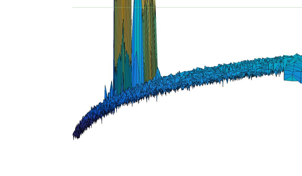
44 CHAPTER 3. RESULTS 3.1. PHASED ARRAY SYSTEM TOOLBOX m from the antenna. They are placed at 7.6 and 38.7 in bearing angle respectively. The speed vectors of the two targets were [ 1; ; ] and [1; 8; ] m/s (one of them approaches and the other goes away). This is presented in Figure Simulated received data with PAS toolbox Range bin Pulse index Figure 3.11: Simulated received data with two targets. One can see in Figure 3.11 that there are two areas where the signal strength is stronger than the surrounding. These yellow dots are the return from the targets, while the blue is from noise. It is shown in Figure 3.12 how the simulated data has changed after pulse compression. Pulse compression on simulated data Range bin Pulse index Figure 3.12: The simulated data after pulse compression. One can see on the scale bar that the signal strength increased with 1 db. It is also possible to see a narrow line in the centre of the yellow areas. In order to easier see the result of pulse compression, a cross section was done for each target. The cross sections were taken at pulse indices where local maxima occur. In Figure 3.13 is the cross section shown at pulse index
45 -2-3 Signal before and after pulse compression at pulse index 166 Received signal Pulse compressed signal -4 Power [db] Range bin -2-3 Enlargement of the peak at pulse index 166 Received signal Pulse compressed signal -4-5 Power [db] Range bin
46 -2-3 Signal before and after pulse compression at pulse index 3 Received signal Pulse compressed signal -4 Power [db] Range bin Enlargement of the peak at pulse index 3-3 Received signal Pulse compressed signal -4-5 Power [db] Range bin
47 -2 Pulse nr 1 Power [db] Power [db] Range bin Pulse nr Power [db] Range bin Integration over all pulses Range bin Integrated over all pulses -3-4 Power [db] Range bin
48 -2 Pulse nr 1 Power [db] Power [db] Power [db] Range bin Integration over all pulses Integration over all pulses Power [db] Range bin
49 Pulse nr 1 Power [db] Power [db] Range bin Pulse nr Range bin -5 Integration over all pulses Power [db] Range bin Integration over all pulses -4-5 Power [db] Range bin
50 Pulse nr 1 Power [db] Power [db] Range bin Pulse nr Range bin -5 Integration over all pulses Power [db] Range bin Integration over all pulses -4-5 Power [db] Range bin


![-12-14 Power [db]](/docs-images/90/102877743/images/51-2.jpg "-16-18")

51 3D response of targets in polar coordinates with threshold Power [db] D response of targets in polar coordinates with threshold Power [db]
52 CHAPTER 3. RESULTS 3.1. PHASED ARRAY SYSTEM TOOLBOX it is better to do for the maximum value. The simulated values are compared with the estimated from Figure 3.13 and 3.15 is presented in Table 3.1. Table 3.1: Comparison between simulated and estimated value from maximum value. Target First Second Simulated range [m] Estimated range [m] Difference [m] One can see that using that by using the estimated maximum value, it is more consistent with the simulated. Both targets were estimated to the same radial velocity, namely 46.5 m/s. The difference in time required for signal processing using the current model and implementation with PAS system is present in the table below. Table 3.2: Time required for different moments in the signal process. Process Pulse compression GCG Pulse compression Air Time current model [s] Time PAS [s] Difference [s] The TVG system object was not successfully implemented in the current system and thus could not compare the time required. Using the current model to simulate the received signal with a target located m from the radar in order to compared with PAS simulation in Figure In order to compare the PAS toolbox with the current model, a received signal was simulated with the same properties. A target was simulated m from the radar system. The data simulated with the current system that should be compared with the PAS simulation in Figure 3.11, is presented in Figure Simulated data with current model Power Range bin Pulse index Figure 3.27: The simulated data with one target present with current model. 44
53 3.1. PHASED ARRAY SYSTEM TOOLBOX CHAPTER 3. RESULTS The simulated image shows similar behaviour to the one with PAS. One can see an area where the signal is stronger than the surrounding, where the plane is, and the blue area with noise. This data was also treated with pulse compression. The result of it is presented in Figure Data after pulse compression Power Range bin 12 4 Pulse index Figure 3.28: The simulated after pulse compression. There is one major difference between Figure 3.12 and One can see that the yellow area became much more narrow for the current model than for the PAS toolbox. By taking a cross section at the pulse index where the maximum signal strength occurs, the effect of pulse compression can be shown. It can be seen in Figure 3.29 how the signal increased in strength and became narrower after pulse compression. Signal before and after pulse compression at pulse index Received signal Pulse compressed signal 7 SNR/Noise floor [db] Range bin Figure 3.29: Profile of the data before and after pulse compression at pulse index 121. After pulse compression, the position of the target is estimated at a distance of m. The difference between the simulated distance and the estimated were roughly 4 m. Using a large number of simulation (1), the average difference between simulated and estimated distance 45
54 Bearing Plane orientation degrees, and wing angle 9 degrees 1 Plane front Plane back Apex of left wing.5 Left engine Apex of right wing Right engine Bearing Plane orientation degrees, and wing angle 11 degrees Range Range Plane orientation degrees, and wing angle 13 degrees 1 Plane orientation degrees, and wing angle 15 degrees Bearing Bearing Range Range
55 Plane orientation 45 degrees, and wing angle 11 degrees 1.5 Plane orientation 9 degrees, and wing angle 11 degrees Bearing Bearing Range Range Plane orientation 11 degrees, and wing angle 11 degrees 1.5 Bearing Range Plane orientation 18 degrees, and wing angle 11 degrees.8 Bearing Range
56 Two simulated plane target with a different orientation
57 Elevation Elevation Bearing angle Range [m] Estimation of plane Estimation of point Simulated point Bearing angle Range [m] Range [m] Bearing angle Elevation
58 Data for point target at range bin with maximum power Data for point target at range bin + 1 Data for point target at range bin - 1 Bearing correction with new estimation for point target Bearing correction with current model for point target Data for plane target at range bin with maximum power Data for plane taget at range bin + 1 Data for plane target at range bin - 1 Bearing correction with new estimation for plane target Bearing correction with current model for plane target Power as function of bearing angle 128 Range number Power Bearing angle 25 3
59 Power as function of bearing angle 124 Range number Power Bearing angle 3
60 3 Power as function of bearing angle 25 2 Power Bearing angle Power as function of bearing angle 25 2 Power Bearing angle
61 7 Power as function of bearing angle 6 5 Power Bearing angle
62 Power as function of bearing angle Power Bearing angle
63
64
65 1 x 99.25
66 k
67
68
69
70
71
INTRODUCTION TO RADAR SIGNAL PROCESSING
 INTRODUCTION TO RADAR SIGNAL PROCESSING Christos Ilioudis University of Strathclyde c.ilioudis@strath.ac.uk Overview History of Radar Basic Principles Principles of Measurements Coherent and Doppler Processing
EE 529 Remote Sensing Techniques. Radar
 EE 59 Remote Sensing Techniques Radar Outline Radar Resolution Radar Range Equation Signal-to-Noise Ratio Doppler Frequency Basic function of an active radar Radar RADAR: Radio Detection and Ranging Detection
DOPPLER RADAR. Doppler Velocities - The Doppler shift. if φ 0 = 0, then φ = 4π. where
 Q: How does the radar get velocity information on the particles? DOPPLER RADAR Doppler Velocities - The Doppler shift Simple Example: Measures a Doppler shift - change in frequency of radiation due to
Set No.1. Code No: R
 Set No.1 IV B.Tech. I Semester Regular Examinations, November -2008 RADAR SYSTEMS ( Common to Electronics & Communication Engineering and Electronics & Telematics) Time: 3 hours Max Marks: 80 Answer any
Introduction to Radar Systems. Radar Antennas. MIT Lincoln Laboratory. Radar Antennas - 1 PRH 6/18/02
 Introduction to Radar Systems Radar Antennas Radar Antennas - 1 Disclaimer of Endorsement and Liability The video courseware and accompanying viewgraphs presented on this server were prepared as an account
Lecture 9. Radar Equation. Dr. Aamer Iqbal. Radar Signal Processing Dr. Aamer Iqbal Bhatti
 Lecture 9 Radar Equation Dr. Aamer Iqbal 1 ystem Losses: Losses within the radar system itself are from many sources. everal are described below. L PL =the plumbing loss. L PO =the polarization loss. L
Time and Frequency Domain Windowing of LFM Pulses Mark A. Richards
 Time and Frequency Domain Mark A. Richards September 29, 26 1 Frequency Domain Windowing of LFM Waveforms in Fundamentals of Radar Signal Processing Section 4.7.1 of [1] discusses the reduction of time
ADAPTIVE ANTENNAS. TYPES OF BEAMFORMING
 ADAPTIVE ANTENNAS TYPES OF BEAMFORMING 1 1- Outlines This chapter will introduce : Essential terminologies for beamforming; BF Demonstrating the function of the complex weights and how the phase and amplitude
Final Examination. 22 April 2013, 9:30 12:00. Examiner: Prof. Sean V. Hum. All non-programmable electronic calculators are allowed.
 UNIVERSITY OF TORONTO FACULTY OF APPLIED SCIENCE AND ENGINEERING The Edward S. Rogers Sr. Department of Electrical and Computer Engineering ECE 422H1S RADIO AND MICROWAVE WIRELESS SYSTEMS Final Examination
Continuous Arrays Page 1. Continuous Arrays. 1 One-dimensional Continuous Arrays. Figure 1: Continuous array N 1 AF = I m e jkz cos θ (1) m=0
 m=0") Continuous Arrays Page 1 Continuous Arrays 1 One-dimensional Continuous Arrays Consider the 2-element array we studied earlier where each element is driven by the same signal (a uniform excited array),
Continuous Arrays Page 1 Continuous Arrays 1 One-dimensional Continuous Arrays Consider the 2-element array we studied earlier where each element is driven by the same signal (a uniform excited array),
Monopulse Antenna. Figure 2: sectional picture of an antenna array of a monopulse antenna
 Monopulse Antenna Figure 1: Principle of monopulse antenna Figure 2: sectional picture of an antenna array of a monopulse antenna Under this concept antennae are combined which are built up as an antenna
UNIT Explain the radiation from two-wire. Ans: Radiation from Two wire
 UNIT 1 1. Explain the radiation from two-wire. Radiation from Two wire Figure1.1.1 shows a voltage source connected two-wire transmission line which is further connected to an antenna. An electric field
Lecture 6 SIGNAL PROCESSING. Radar Signal Processing Dr. Aamer Iqbal Bhatti. Dr. Aamer Iqbal Bhatti
 Lecture 6 SIGNAL PROCESSING Signal Reception Receiver Bandwidth Pulse Shape Power Relation Beam Width Pulse Repetition Frequency Antenna Gain Radar Cross Section of Target. Signal-to-noise ratio Receiver
INTRODUCTION. Basic operating principle Tracking radars Techniques of target detection Examples of monopulse radar systems
 Tracking Radar H.P INTRODUCTION Basic operating principle Tracking radars Techniques of target detection Examples of monopulse radar systems 2 RADAR FUNCTIONS NORMAL RADAR FUNCTIONS 1. Range (from pulse
ESCI Cloud Physics and Precipitation Processes Lesson 10 - Weather Radar Dr. DeCaria
 ESCI 340 - Cloud Physics and Precipitation Processes Lesson 10 - Weather Radar Dr. DeCaria References: A Short Course in Cloud Physics, 3rd ed., Rogers and Yau, Ch. 11 Radar Principles The components of
Scalable Front-End Digital Signal Processing for a Phased Array Radar Demonstrator. International Radar Symposium 2012 Warsaw, 24 May 2012
 Scalable Front-End Digital Signal Processing for a Phased Array Radar Demonstrator F. Winterstein, G. Sessler, M. Montagna, M. Mendijur, G. Dauron, PM. Besso International Radar Symposium 2012 Warsaw,
Pulse Compression. Since each part of the pulse has unique frequency, the returns can be completely separated.
 Pulse Compression Pulse compression is a generic term that is used to describe a waveshaping process that is produced as a propagating waveform is modified by the electrical network properties of the transmission
Radar Systems Engineering Lecture 15 Parameter Estimation And Tracking Part 1
 Radar Systems Engineering Lecture 15 Parameter Estimation And Tracking Part 1 Dr. Robert M. O Donnell Guest Lecturer Radar Systems Course 1 Block Diagram of Radar System Transmitter Propagation Medium
Lecture Topics. Doppler CW Radar System, FM-CW Radar System, Moving Target Indication Radar System, and Pulsed Doppler Radar System
 Lecture Topics Doppler CW Radar System, FM-CW Radar System, Moving Target Indication Radar System, and Pulsed Doppler Radar System 1 Remember that: An EM wave is a function of both space and time e.g.
UNIT-3. Ans: Arrays of two point sources with equal amplitude and opposite phase:
 `` UNIT-3 1. Derive the field components and draw the field pattern for two point source with spacing of λ/2 and fed with current of equal n magnitude but out of phase by 180 0? Ans: Arrays of two point
ECE 678 Radar Engineering Fall 2018
 ECE 678 Radar Engineering Fall 2018 Prof. Mark R. Bell Purdue University RAdio Detection And Ranging RADAR It has become so commonplace that the acronym RADAR has evolved into a common noun: radar. A
Notes 21 Introduction to Antennas
 ECE 3317 Applied Electromagnetic Waves Prof. David R. Jackson Fall 018 Notes 1 Introduction to Antennas 1 Introduction to Antennas Antennas An antenna is a device that is used to transmit and/or receive
Mathematical models for radiodetermination radar systems antenna patterns for use in interference analyses
 Recommendation ITU-R M.1851-1 (1/18) Mathematical models for radiodetermination radar systems antenna patterns for use in interference analyses M Series Mobile, radiodetermination, amateur and related
Pulse Compression Time-Bandwidth Product. Chapter 5
 Chapter 5 Pulse Compression Range resolution for a given radar can be significantly improved by using very short pulses. Unfortunately, utilizing short pulses decreases the average transmitted power, which
Modern radio techniques
 Modern radio techniques for probing the ionosphere Receiver, radar, advanced ionospheric sounder, and related techniques Cesidio Bianchi INGV - Roma Italy Ionospheric properties related to radio waves
Introduction to Radar Basics
 Chapter 1 Introduction to Radar Basics 1.1. Radar Classifications The word radar is an abbreviation for RAdio Detection And Ranging. In general, radar systems use modulated waveforms and directive antennas
CHAPTER 5 THEORY AND TYPES OF ANTENNAS. 5.1 Introduction
 CHAPTER 5 THEORY AND TYPES OF ANTENNAS 5.1 Introduction Antenna is an integral part of wireless communication systems, considered as an interface between transmission line and free space [16]. Antenna
Introduction Antenna Ranges Radiation Patterns Gain Measurements Directivity Measurements Impedance Measurements Polarization Measurements Scale
 Chapter 17 : Antenna Measurement Introduction Antenna Ranges Radiation Patterns Gain Measurements Directivity Measurements Impedance Measurements Polarization Measurements Scale Model Measurements 1 Introduction
Dr. John S. Seybold. November 9, IEEE Melbourne COM/SP AP/MTT Chapters
 Antennas Dr. John S. Seybold November 9, 004 IEEE Melbourne COM/SP AP/MTT Chapters Introduction The antenna is the air interface of a communication system An antenna is an electrical conductor or system
Antenna Engineering Lecture 3: Basic Antenna Parameters
 Antenna Engineering Lecture 3: Basic Antenna Parameters ELC 405a Fall 2011 Department of Electronics and Communications Engineering Faculty of Engineering Cairo University 2 Outline 1 Radiation Pattern
Antenna & Propagation. Antenna Parameters
 For updated version, please click on http://ocw.ump.edu.my Antenna & Propagation Antenna Parameters by Nor Hadzfizah Binti Mohd Radi Faculty of Electric & Electronics Engineering hadzfizah@ump.edu.my Chapter
ELEC RADAR FRONT-END SUMMARY
 ELEC Radar Front-End is designed for FMCW (including CW) radar application. The output frequency of each RX provides range, speed, and amplitude information to DSP. It will detect target azimuth angle
Narrow- and wideband channels
 RADIO SYSTEMS ETIN15 Lecture no: 3 Narrow- and wideband channels Ove Edfors, Department of Electrical and Information technology Ove.Edfors@eit.lth.se 2012-03-19 Ove Edfors - ETIN15 1 Contents Short review
Design of an Airborne SLAR Antenna at X-Band
 Design of an Airborne SLAR Antenna at X-Band Markus Limbach German Aerospace Center (DLR) Microwaves and Radar Institute Oberpfaffenhofen WFMN 2007, Markus Limbach, Folie 1 Overview Applications of SLAR
RF Systems I. Erk Jensen, CERN BE-RF
 RF Systems I Erk Jensen, CERN BE-RF Introduction to Accelerator Physics, Prague, Czech Republic, 31 Aug 12 Sept 2014 Definitions & basic concepts db t-domain vs. ω-domain phasors 8th Sept, 2014 CAS Prague
STATISTICAL DISTRIBUTION OF INCIDENT WAVES TO MOBILE ANTENNA IN MICROCELLULAR ENVIRONMENT AT 2.15 GHz
 EUROPEAN COOPERATION IN COST259 TD(99) 45 THE FIELD OF SCIENTIFIC AND Wien, April 22 23, 1999 TECHNICAL RESEARCH EURO-COST STATISTICAL DISTRIBUTION OF INCIDENT WAVES TO MOBILE ANTENNA IN MICROCELLULAR
10 Antenna gain, beam pattern, directivity
 10 Antenna gain, beam pattern, directivity Adipoleantenna(oracloselyrelatedmonopoletobestudiedinLecture 18) is a near perfect radiator for purposes of broadcasting that is, sending waves of equal amplitudes
( ) 2 ( ) 3 ( ) + 1. cos! t " R / v p 1 ) H =! ˆ" I #l ' $ 2 ' 2 (18.20) * + ! ˆ& "I #l ' $ 2 ' , ( βr << 1. "l ' E! ˆR I 0"l ' cos& + ˆ& 0
 2 ( ) 3 ( ) + 1. cos! t R / v p 1 ) H =! ˆ I #l ' $ 2 ' 2 (18.20) * + ! ˆ& I #l ' $ 2 ' , ( βr << 1. l ' E! ˆR I 0l ' cos& + ˆ& 0") Summary Chapter 8. This last chapter treats the problem of antennas and radiation from antennas. We start with the elemental electric dipole and introduce the idea of retardation of potentials and fields
Summary Chapter 8. This last chapter treats the problem of antennas and radiation from antennas. We start with the elemental electric dipole and introduce the idea of retardation of potentials and fields
THE DIGITAL IFM RECEIVER REVISITED THE DIGITAL IFM RECEIVER REVISITED. by S. V. Potter
 THE DIGITAL IFM RECEIVER REVISITED by S. V. Potter 1 Introduction s Since the outbreak of world War 2 two varieties of radar ESM have developed, namely, elint, wich is concerned with gathering particulars
Frequency diverse array radar. Monterey, California Naval Postgraduate School. Issue Date
 Author(s) Aytun, Alper. Title Frequency diverse array radar Publisher Monterey, California Naval Postgraduate School Issue Date 21-9 URL http://hdl.handle.net/1945/5113 This document was downloaded on
Ultrasound Beamforming and Image Formation. Jeremy J. Dahl
 Ultrasound Beamforming and Image Formation Jeremy J. Dahl Overview Ultrasound Concepts Beamforming Image Formation Absorption and TGC Advanced Beamforming Techniques Synthetic Receive Aperture Parallel
ECE 476/ECE 501C/CS Wireless Communication Systems Winter Lecture 6: Fading
 ECE 476/ECE 501C/CS 513 - Wireless Communication Systems Winter 2003 Lecture 6: Fading Last lecture: Large scale propagation properties of wireless systems - slowly varying properties that depend primarily
PLANAR BEAM-FORMING ARRAY FOR BROADBAND COMMUNICATION IN THE 60 GHZ BAND
 PLANAR BEAM-FORMING ARRAY FOR BROADBAND COMMUNICATION IN THE 6 GHZ BAND J.A.G. Akkermans and M.H.A.J. Herben Radiocommunications group, Eindhoven University of Technology, Eindhoven, The Netherlands, e-mail:
ECE 476/ECE 501C/CS Wireless Communication Systems Winter Lecture 6: Fading
 ECE 476/ECE 501C/CS 513 - Wireless Communication Systems Winter 2005 Lecture 6: Fading Last lecture: Large scale propagation properties of wireless systems - slowly varying properties that depend primarily
ECE 476/ECE 501C/CS Wireless Communication Systems Winter Lecture 6: Fading
 ECE 476/ECE 501C/CS 513 - Wireless Communication Systems Winter 2004 Lecture 6: Fading Last lecture: Large scale propagation properties of wireless systems - slowly varying properties that depend primarily
Simulating and Testing of Signal Processing Methods for Frequency Stepped Chirp Radar
 Test & Measurement Simulating and Testing of Signal Processing Methods for Frequency Stepped Chirp Radar Modern radar systems serve a broad range of commercial, civil, scientific and military applications.
BYU SAR: A LOW COST COMPACT SYNTHETIC APERTURE RADAR
 BYU SAR: A LOW COST COMPACT SYNTHETIC APERTURE RADAR David G. Long, Bryan Jarrett, David V. Arnold, Jorge Cano ABSTRACT Synthetic Aperture Radar (SAR) systems are typically very complex and expensive.
MOBILE RAPID-SCANNING X-BAND POLARIMETRIC (RaXPol) DOPPLER RADAR SYSTEM Andrew L. Pazmany 1 * and Howard B. Bluestein 2
 DOPPLER RADAR SYSTEM Andrew L. Pazmany 1 * and Howard B. Bluestein 2") 16B.2 MOBILE RAPID-SCANNING X-BAND POLARIMETRIC (RaXPol) DOPPLER RADAR SYSTEM Andrew L. Pazmany 1 * and Howard B. Bluestein 2 1 ProSensing Inc., Amherst, Massachusetts 2 University of Oklahoma, Norman,
16B.2 MOBILE RAPID-SCANNING X-BAND POLARIMETRIC (RaXPol) DOPPLER RADAR SYSTEM Andrew L. Pazmany 1 * and Howard B. Bluestein 2 1 ProSensing Inc., Amherst, Massachusetts 2 University of Oklahoma, Norman,
Exercise 1-3. Radar Antennas EXERCISE OBJECTIVE DISCUSSION OUTLINE DISCUSSION OF FUNDAMENTALS. Antenna types
 Exercise 1-3 Radar Antennas EXERCISE OBJECTIVE When you have completed this exercise, you will be familiar with the role of the antenna in a radar system. You will also be familiar with the intrinsic characteristics
Short Range Millimeter-Wave Inverse Synthetic Aperture Radar Imaging
 Short Range Millimeter-Wave Inverse Synthetic Aperture Radar Imaging OSCAR GYLLING RICKARD STÅHL MASTER S THESIS DEPARTMENT OF ELECTRICAL AND INFORMATION TECHNOLOGY FACULTY OF ENGINEERING LTH LUND UNIVERSITY
INTRODUCTION TO RADAR PROCESSING
 CHAPTER 10 INTRODUCTION TO RADAR PROCESSING This chapter explores some of the ways in which digital filtering and Fast Fourier Transforms are applied to radar signal processing. Radar signal processing
UNIT Write short notes on travelling wave antenna? Ans: Travelling Wave Antenna
 UNIT 4 1. Write short notes on travelling wave antenna? Travelling Wave Antenna Travelling wave or non-resonant or aperiodic antennas are those antennas in which there is no reflected wave i.e., standing
Active Cancellation Algorithm for Radar Cross Section Reduction
 International Journal of Computational Engineering Research Vol, 3 Issue, 7 Active Cancellation Algorithm for Radar Cross Section Reduction Isam Abdelnabi Osman, Mustafa Osman Ali Abdelrasoul Jabar Alzebaidi
ANTENNAS AND WAVE PROPAGATION EC602
 ANTENNAS AND WAVE PROPAGATION EC602 B.Tech Electronics & Communication Engineering, Semester VI INSTITUTE OF TECHNOLOGY NIRMA UNIVERSITY 1 Lesson Planning (L-3,P-2,C-4) Chapter No. Name Hours 1. Basic
HIGH RESOLUTION MULTI-BEAM SIDE LOOKING SONAR ANDRZEJ ELMINOWICZ, LEONARD ZAJĄCZKOWSKI
 HIGH RESOLUTION MULTI-BEAM SIDE LOOKING SONAR ANDRZEJ ELMINOWICZ, LEONARD ZAJĄCZKOWSKI R&D Marine Technology Centre Dickmana 62, 81-109 Gdynia, POLAND email: andrzeje@ctm.gdynia.pl The conventional side
FM cw Radar. FM cw Radar is a low cost technique, often used in shorter range applications"
 11: FM cw Radar 9. FM cw Radar 9.1 Principles 9.2 Radar equation 9.3 Equivalence to pulse compression 9.4 Moving targets 9.5 Practical considerations 9.6 Digital generation of wideband chirp signals FM
S. K. Sanyal Department of Electronics and Telecommunication Engineering Jadavpur University Kolkata, , India
 Progress In Electromagnetics Research, PIER 60, 187 196, 2006 A NOVEL BEAM-SWICHING ALGORIHM FOR PROGRAMMABLE PHASED ARRAY ANENNA S. K. Sanyal Department of Electronics and elecommunication Engineering
An Improved DBF Processor with a Large Receiving Antenna for Echoes Separation in Spaceborne SAR
 Progress In Electromagnetics Research C, Vol. 67, 49 57, 216 An Improved DBF Processor a Large Receiving Antenna for Echoes Separation in Spaceborne SAR Hongbo Mo 1, *,WeiXu 2, and Zhimin Zeng 1 Abstract
ANTENNA INTRODUCTION / BASICS
 ANTENNA INTRODUCTION / BASICS RULES OF THUMB: 1. The Gain of an antenna with losses is given by: 2. Gain of rectangular X-Band Aperture G = 1.4 LW L = length of aperture in cm Where: W = width of aperture
Antenna Design Seminar
 Antenna Design Seminar What we are going to cover This seminar will cover the design concepts of a variety of broadcast antennas that relates to the design of TV and FM antennas. We will first look at
Travelling Wave, Broadband, and Frequency Independent Antennas. EE-4382/ Antenna Engineering
 Travelling Wave, Broadband, and Frequency Independent Antennas EE-4382/5306 - Antenna Engineering Outline Traveling Wave Antennas Introduction Traveling Wave Antennas: Long Wire, V Antenna, Rhombic Antenna
Chapter 2. Fundamental Properties of Antennas. ECE 5318/6352 Antenna Engineering Dr. Stuart Long
 Chapter Fundamental Properties of Antennas ECE 5318/635 Antenna Engineering Dr. Stuart Long 1 IEEE Standards Definition of Terms for Antennas IEEE Standard 145-1983 IEEE Transactions on Antennas and Propagation
Low Altitude Airspace Monitoring at Sea
 NTNU Low Altitude Airspace Monitoring at Sea Radar Signal Processing, Path Planning and Collision Avoidance Master Thesis in Systems, Control and Mechatronics MOHAMMED RAZAUL KARIM Department of Signals
Topic 3. Fundamental Parameters of Antennas. Tamer Abuelfadl
 Topic 3 Fundamental Parameters of Antennas Tamer Abuelfadl Electronics and Electrical Communications Department Faculty of Engineering Cairo University Tamer Abuelfadl (EEC, Cairo University) Topic 3 ELC
Space-Time Adaptive Processing Using Sparse Arrays
 Space-Time Adaptive Processing Using Sparse Arrays Michael Zatman 11 th Annual ASAP Workshop March 11 th -14 th 2003 This work was sponsored by the DARPA under Air Force Contract F19628-00-C-0002. Opinions,
ANTENNA INTRODUCTION / BASICS
 Rules of Thumb: 1. The Gain of an antenna with losses is given by: G 0A 8 Where 0 ' Efficiency A ' Physical aperture area 8 ' wavelength ANTENNA INTRODUCTION / BASICS another is:. Gain of rectangular X-Band
EITN90 Radar and Remote Sensing Lecture 2: The Radar Range Equation
 EITN90 Radar and Remote Sensing Lecture 2: The Radar Range Equation Daniel Sjöberg Department of Electrical and Information Technology Spring 2018 Outline 1 Radar Range Equation Received power Signal to
Half-Wave Dipole. Radiation Resistance. Antenna Efficiency
 Antennas Simple Antennas Isotropic radiator is the simplest antenna mathematically Radiates all the power supplied to it, equally in all directions Theoretical only, can t be built Useful as a reference:
FAQs on AESAs and Highly-Integrated Silicon ICs page 1
 Frequently Asked Questions on AESAs and Highly-Integrated Silicon ICs What is an AESA? An AESA is an Active Electronically Scanned Antenna, also known as a phased array antenna. As defined by Robert Mailloux,
High Range Resolution Micro-Doppler Radar Theory and Its. Application to Human Gait Classification
 High Range Resolution Micro-Doppler Radar Theory and Its Application to Human Gait Classification DISSERTATION Presented in Partial Fulfillment of the Requirements for the Degree Doctor of Philosophy in
Lecture on Angular Vibration Measurements Based on Phase Demodulation
 Lecture on Angular Vibration Measurements Based on Phase Demodulation JiříTůma VSB Technical University of Ostrava Czech Republic Outline Motivation Principle of phase demodulation using Hilbert transform
This article reports on
 Millimeter-Wave FMCW Radar Transceiver/Antenna for Automotive Applications A summary of the design and performance of a 77 GHz radar unit David D. Li, Sam C. Luo and Robert M. Knox Epsilon Lambda Electronics
1. Clearly circle one answer for each part.
 TB 1-9 / Exam Style Questions 1 EXAM STYLE QUESTIONS Covering Chapters 1-9 of Telecommunication Breakdown 1. Clearly circle one answer for each part. (a) TRUE or FALSE: Absolute bandwidth is never less
A Passive Suppressing Jamming Method for FMCW SAR Based on Micromotion Modulation
 Progress In Electromagnetics Research M, Vol. 48, 37 44, 216 A Passive Suppressing Jamming Method for FMCW SAR Based on Micromotion Modulation Jia-Bing Yan *, Ying Liang, Yong-An Chen, Qun Zhang, and Li
Radar observables: Target range Target angles (azimuth & elevation) Target size (radar cross section) Target speed (Doppler) Target features (imaging)
 Target size (radar cross section) Target speed (Doppler) Target features (imaging)") Fundamentals of Radar Prof. N.V.S.N. Sarma Outline 1. Definition and Principles of radar 2. Radar Frequencies 3. Radar Types and Applications 4. Radar Operation 5. Radar modes What What is is Radar? Radar?
Fundamentals of Radar Prof. N.V.S.N. Sarma Outline 1. Definition and Principles of radar 2. Radar Frequencies 3. Radar Types and Applications 4. Radar Operation 5. Radar modes What What is is Radar? Radar?
Intermodulation in Active Array Receive Antennas
 Intermodulation in Active Array Receive Antennas Klaus Solbach, Universität Duisburg, Hochfrequenztechnik, 47048 Duisburg, Tel. 00-79-86, Fax -498, Email: hft@uni-duisburg.de and Markus Böck, Antenna Technology
Digital Signal Processing (DSP) Algorithms for CW/FMCW Portable Radar
 Algorithms for CW/FMCW Portable Radar") Digital Signal Processing (DSP) Algorithms for CW/FMCW Portable Radar Muhammad Zeeshan Mumtaz, Ali Hanif, Ali Javed Hashmi National University of Sciences and Technology (NUST), Islamabad, Pakistan Abstract
Digital Signal Processing (DSP) Algorithms for CW/FMCW Portable Radar Muhammad Zeeshan Mumtaz, Ali Hanif, Ali Javed Hashmi National University of Sciences and Technology (NUST), Islamabad, Pakistan Abstract
THE UTILITY OF SYNTHETIC APERTURE SONAR IN SEAFLOOR IMAGING MARCIN SZCZEGIELNIAK
 THE UTILITY OF SYNTHETIC APERTURE SONAR IN SEAFLOOR IMAGING MARCIN SZCZEGIELNIAK University of Technology and Agriculture in Bydgoszcz 7 Kalisky Ave, 85-79 Bydgoszcz, Poland e-mail: marcinszczegielniak@poczta.onet.pl
Characteristics of HF Coastal Radars
 Function Characteristics System 1 Maximum operational (measurement) range** Characteristics of HF Coastal Radars 5 MHz Long-range oceanographic 160-220 km average during (daytime)* System 2 System 3 System
The Analysis of the Airplane Flutter on Low Band Television Broadcasting Signal
 The Analysis of the Airplane Flutter on Low Band Television Broadcasting Signal A. Wonggeeratikun 1,2, S. Noppanakeepong 1, N. Leelaruji 1, N. Hemmakorn 1, and Y. Moriya 1 1 Faculty of Engineering and
The Old Cat and Mouse Game Continues
 The Old Cat and Mouse Game Continues or, How Advances in Radar Development Drive Testing Requirements for Next Generation EW Systems by: Walt Schulte Agilent Technologies Microwave and Communications Division
Narrow- and wideband channels
 RADIO SYSTEMS ETIN15 Lecture no: 3 Narrow- and wideband channels Ove Edfors, Department of Electrical and Information technology Ove.Edfors@eit.lth.se 27 March 2017 1 Contents Short review NARROW-BAND
Optimization of Digital Signal Processing Techniques for Surveillance RADAR
 RESEARCH ARTICLE OPEN ACCESS Optimization of Digital Signal Processing Techniques for Surveillance RADAR Sonia Sethi, RanadeepSaha, JyotiSawant M.E. Student, Thakur College of Engineering & Technology,
ANTENNAS 101 An Introduction to Antennas for Ham Radio. Lee KD4RE
 ANTENNAS 101 An Introduction to Antennas for Ham Radio Lee KD4RE Prepared for Presentation at the Vienna Wireless Society, 13 January 2017 So What is an Antenna Anyway? We are all familiar with wire antennas
Naval Surveillance Multi-beam Active Phased Array Radar (MAARS)
") Naval Surveillance Multi-beam Active Phased Array Radar (MAARS) MAARS MAARS purpose: MAARS is multimode C-band acquisition radar for surveillance and weapon assignment. It perform automatic detection,
Naval Surveillance Multi-beam Active Phased Array Radar (MAARS) MAARS MAARS purpose: MAARS is multimode C-band acquisition radar for surveillance and weapon assignment. It perform automatic detection,
Antenna Parameters. Ranga Rodrigo. University of Moratuwa. December 15, 2008
 Antenna Parameters Ranga Rodrigo University of Moratuwa December 15, 2008 Ranga Rodrigo (University of Moratuwa) Antenna Parameters December 15, 2008 1 / 47 Summary of Last Week s Lecture 90 o Radiation
Radar Systems Engineering Lecture 12 Clutter Rejection
 Radar Systems Engineering Lecture 12 Clutter Rejection Part 1 - Basics and Moving Target Indication Dr. Robert M. O Donnell Guest Lecturer Radar Systems Course 1 Block Diagram of Radar System Transmitter
Antenna Arrays. EE-4382/ Antenna Engineering
 Antenna Arrays EE-4382/5306 - Antenna Engineering Outline Introduction Two Element Array Rectangular-to-Polar Graphical Solution N-Element Linear Array: Uniform Spacing and Amplitude Theory of N-Element
6.014 Lecture 6: Multipath, Arrays, and Frequency Reuse
 6.014 Lecture 6: Multipath, Arrays, and Frequency Reuse A. Superposition of phasors This lecture focuses on the superposition of duplicate waves at receivers, where the multiplicity of waves may have originated
COMPUTED ENVELOPE LINEARITY OF SEVERAL FM BROADCAST ANTENNA ARRAYS
 COMPUTED ENVELOPE LINEARITY OF SEVERAL FM BROADCAST ANTENNA ARRAYS J. DANE JUBERA JAMPRO ANTENNAS, INC PRESENTED AT THE 28 NAB ENGINEERING CONFERENCE APRIL 16, 28 LAS VEGAS, NV COMPUTED ENVELOPE LINEARITY
Reduction in sidelobe and SNR improves by using Digital Pulse Compression Technique
 Reduction in sidelobe and SNR improves by using Digital Pulse Compression Technique Devesh Tiwari 1, Dr. Sarita Singh Bhadauria 2 Department of Electronics Engineering, Madhav Institute of Technology and
EMG4066:Antennas and Propagation Exp 1:ANTENNAS MMU:FOE. To study the radiation pattern characteristics of various types of antennas.
 OBJECTIVES To study the radiation pattern characteristics of various types of antennas. APPARATUS Microwave Source Rotating Antenna Platform Measurement Interface Transmitting Horn Antenna Dipole and Yagi
Chapter 5 Small-Scale Fading and Multipath. School of Information Science and Engineering, SDU
 Chapter 5 Small-Scale Fading and Multipath School of Information Science and Engineering, SDU Outline Small-Scale Multipath Propagation Impulse Response Model of a Multipath Channel Small-Scale Multipath
24 GHz Patch Antenna Array Design for RADAR
 Master s Thesis 24 GHz Patch Antenna Array Design for RADAR Karl Nordin Sina Shamekhi Department of Electrical and Information Technology, Faculty of Engineering, LTH, Lund University, 2016. 24 GHz Patch
DIGITAL BEAM-FORMING ANTENNA OPTIMIZATION FOR REFLECTOR BASED SPACE DEBRIS RADAR SYSTEM
 DIGITAL BEAM-FORMING ANTENNA OPTIMIZATION FOR REFLECTOR BASED SPACE DEBRIS RADAR SYSTEM A. Patyuchenko, M. Younis, G. Krieger German Aerospace Center (DLR), Microwaves and Radar Institute, Muenchner Strasse
Module 2- Antenna: Radiation characteristics of antenna, radiation resistance, short dipole antenna, half wave dipole antenna, loop antenna
 Module - Antenna: Radiation characteristics of antenna, radiation resistance, short dipole antenna, half wave dipole antenna, loop antenna ELL 1 Instructor: Debanjan Bhowmik Department of Electrical Engineering
Tracking of Moving Targets with MIMO Radar
 Tracking of Moving Targets with MIMO Radar Peter W. Moo, Zhen Ding Radar Sensing & Exploitation Section DRDC Ottawa Research Centre Presentation to 2017 NATO Military Sensing Symposium 31 May 2017 waveform
Antenna Beam Broadening in Multifunction Phased Array Radar
 Vol. 119 (2011) ACTA PHYSICA POLONICA A No. 4 Physical Aspects of Microwave and Radar Applications Antenna Beam Broadening in Multifunction Phased Array Radar R. Fatemi Mofrad and R.A. Sadeghzadeh Electrical
Waveform-Agile Sensing for Range and DoA Estimation in MIMO Radars
 Waveform-Agile ensing for Range and DoA Estimation in MIMO Radars Bhavana B. Manjunath, Jun Jason Zhang, Antonia Papandreou-uppappola, and Darryl Morrell enip Center, Department of Electrical Engineering,
COMMUNICATION SYSTEMS-II (In continuation with Part-I)
") MODULATING A SIGNAL COMMUNICATION SYSTEMS-II (In continuation with Part-I) TRANSMITTING SIGNALS : In order to transmit the original low frequency baseband message efficiently over long distances, the signal
MODULATING A SIGNAL COMMUNICATION SYSTEMS-II (In continuation with Part-I) TRANSMITTING SIGNALS : In order to transmit the original low frequency baseband message efficiently over long distances, the signal