TAPR DCC Noise in a Digital World
|
|
|
- Lindsay Bell
- 5 years ago
- Views:
Transcription

1
2 TAPR DCC Noise in a Digital World September 15, 2017 Stephen Hicks, N5AC VP Engineering, FlexRadio Systems F L E X R A D I O S Y S T E M S
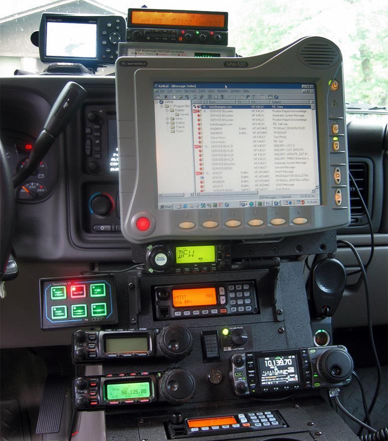
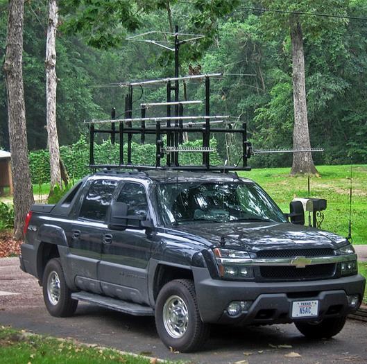
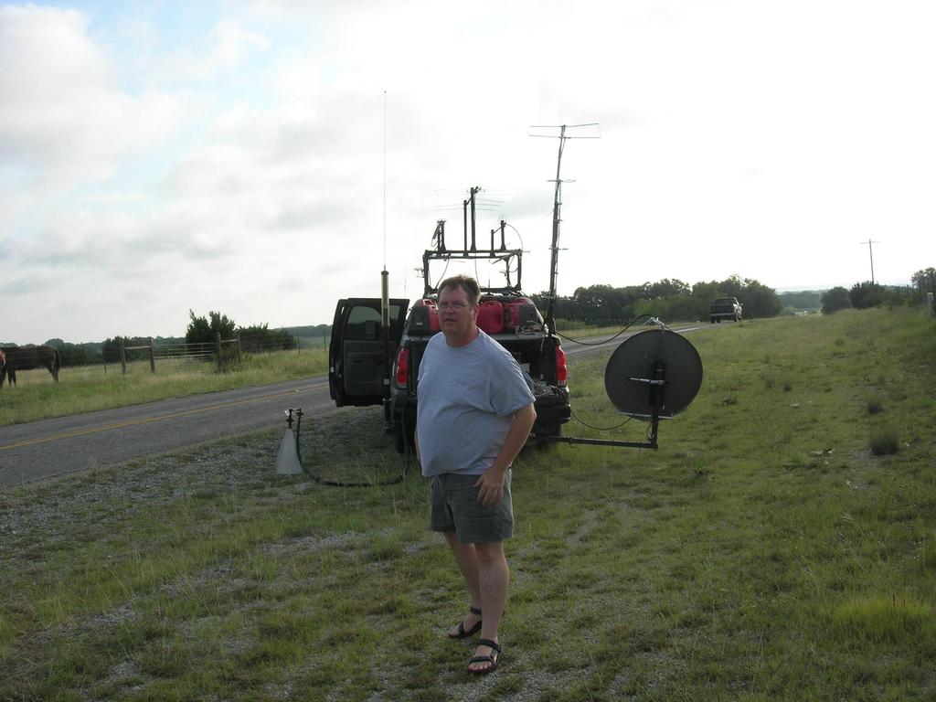
3 About me
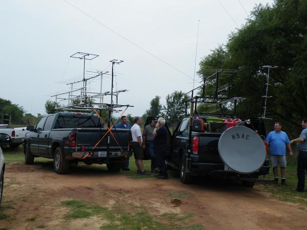
4 About me
5
6
7 TAPR DCC Noise in a Digital World Agenda Knowing Noise db, dbm, mw, W, Oh my Noise Figure, Sensitivity and Gain FLEX-6000 Family Line-Up Q&A
8 Knowing Noise Do you know? Why does the noise floor in my panadapter drop when I change panadapter bandwidth? Is my radio out of calibration if my receiver noise measurement doesn t match my panadapter noise floor? I can see a signal in my panadapter, but I can t hear it my radio must be broken, right?
9 Knowing Noise Do you know? You re selecting a radio do you care about sensitivity, noise figure, preamp gain, something else? Is there a relationship between any of these numbers? Your buddy is boasting about his rig s sensitivity (which is 3dB better than yours). Is this important? Should you be ashamed and trade rigs?
10 3rd order dynamic range. He s lying, right? Knowing Noise Do you know? I looked up the ADC in my direct sampling receiver, it says 16-bits with an ENOB of 12.3 bits and 74dB SNR. I know there are 6dB per bit of dynamic range x 6 = 74. Heck, even if I could use all 16-bits, 16 x 6 = 96dB. My radio manufacturer says it has 105dB of
11 dbm, db, et. al. Quick review db is a measurement of difference in two things (relative) dbm is a measurement of power (db wrt 1mW) 2x power = 3dB, 10x power = 10dB Multiplication in power (W) = Addition in db 1W = 1,000mW 1000 = 10x10x10 = 30dB so 0dBm + 30dB = +30dBm

12 dbm, db, et. al. POP QUIZ! What is 20x power? 10x = 10dB 2x = 3dB so 10 x 2 = 20, and therefore 10dB + 3dB = 13dB What is 200mW in dbm? well 1mW = 0dBm 200 = 10 x 10 x 2 so 10dB + 10dB + 3dB + 0dBm = 23dBm
13 dbm, db, et. al. POP QUIZ! What is 5W in dbm? well 1W = 30dBm 5W = 1W x 10 / 2 = 30dBm + 10dB - 3db = +37dBm What is 4W in dbm? well 1W = 30dBm 4W = 1W x 2 x 2 = 30dBm + 3dB + 3dB = +36dBm TRICKY!
14 Knowing Noise Sources They re everywhere Thermal noise Gaussian noise Flicker Noise Quantization Noise Phase Noise Additive Noise Powerline Noise Splatter Power Supply Noise Atmospheric Noise Spark Noise EMI Noise can be complicated and even those that know it well will have to think and figure on some questions
15 Noise and Bandwidth What is the Noise Floor? We often hear Noise Floor, we know how to point at it, but what is it?

16 Noise Behavior Better get a bucket What your ADC sees: Think of noise as trough of water

")
17 Noise Behavior Better get a bucket What Happens if I split the trough into two troughs? Water level drops by a factor of two (3dB) (note: all computations in the water domain)


 How can you")
18 Noise Behavior Find the diamond There s a diamond at the bottom of the trough I ll give you as many bins as you want, in many sizes (all factors of 2) How can you find the diamond?


19 Noise Behavior Find the diamond What if you split the water into 1024 buckets, each 1/1024 the size of the original trough? Congratulations, you ve just created the first water trough FFT! a.k.a. the WTFFT
20 Noise Behavior OK, what about a RADIO? In a receiver (on an FFT bin), we filter Bandwidth limited to receiver bandwidth Noise is reduced in db by: Think of an FFT as a series of receiver S-Meters stacked next to each other
21 Noise Behavior OK fine, but how does this work in a RADIO? So for our 1024-bin WTFFT, we reduced the water in each bin by:
22 Noise Behavior Why doesn t my signal go down too? If your signal is contained entirely in a single bin, you lose none of it by filtering If your noise is evenly distributed, you reduce it as shown in the previous slide If you split the signal (evenly) across two bins, it will reduce by 3dB in any one bin For the pedantic: yes we re ignoring window leakage, scalloping, etc.


23 Noise Behavior WSJT Noise drops as we narrow bandwidth, exposing the signal
24 Noise Behavior Does this ever NOT work? YES, when not evenly distributed (not AWGN) For example: Frequency dependent noise source Special tools
25 Noise Behavior Review QUESTION: Why does the noise floor in my panadapter drop when I change panadapter bandwidth? ANSWER: We reduce the noise by 3dB each time we reduce the bandwidth by half
26 Noise Behavior Review QUESTION: Is my radio out of calibration if my receiver noise measurement doesn t match my panadapter noise floor? ANSWER: NO, look at the difference in receiver bandwidth and panadapter FFT bin size
27 Noise Behavior Review QUESTION: I can see a signal in my panadapter, but I can t hear it my radio must be broken, right?? ANSWER: NO, a good FFT is generally a better instrument than your ear/brain when the bin size is small (<~50Hz).
28 Noise Behavior Review QUESTION: Assuming your signal strength in your 500Hz receiver (noise only) says - 100dBm and your panadapter shows - 120dBm, what is your FFT bin size? ANSWER: 5Hz
29 Noise Floor Terminology Noise Floor is used haphazardly Vendors, ARRL, etc. use 500Hz bandwidth Noise Floor down as bandwidth is decreased WSJT, CW, etc take advantage of this 12dB below the noise floor, they mean the 500Hz noise floor. If their detector (filtered receiver) is only 10Hz wide, they are hearing 5dB above the actual noise floor for the receiver.
30 Noise and Bandwidth What is the Noise Floor? That s pretty what s the noise floor of that receiver, there?
31 Knowing Noise Do you know? I looked up the ADC in my direct sampling receiver, it says 16-bits with an ENOB of 12.3 bits and 74dB SNR. I know there are 6dB per bit of dynamic range x 6 = 74. Heck, even if I could use all 16-bits, 16 x 6 = 96dB. My radio manufacturer says it has 105dB of 3rd order dynamic range. He s lying, right?
32 Knowing Noise Do you know? 12.4 bits ENOB is spec d at the full bandwidth of the converter We know how to convert lets say we re going from 100MHz to 48kHz 33dB+74dB = 107dB = 17.8-bits Actual bits toggling = 16 * / 6 = 21.5-bits
33 Knowing Noise Do you know? NO, He s not lying
34 Noise Figure, Sensitivity & Gain Oh My! You bought a 6m radio with a stated noise figure of 5dB Where is the noise floor? A. -128dBm B. -135dBm C. -142dBm D. Insufficient Information
35 Noise Figure, Sensitivity & Gain Oh My! TRICK QUESTION!
36 Noise Figure, Sensitivity & Gain Oh My! You bought a 6m radio with a stated noise figure of 5dB Where is the noise floor? A. -128dBm B. -135dBm C. -142dBm D. Insufficient Information
37 Noise Figure, Sensitivity & Gain What you need to know Golden Rule: 0dB NF = -174dBm in 1Hz To calculate the noise floor in ANY bandwidth given the NF and bandwidth: -174dBm + NF + (db bandwidth difference from 1Hz) For example, a receiver with a 5dB NF and a bandwidth of 500Hz has a noise floor of: -174dBm + 5dB + ( ) = -142dBm
38 Noise Figure, Sensitivity & Gain What you need to know What s the golden rule? 0dB NF = -174dBm in 1Hz
39 Noise Figure, Sensitivity & Gain Cascaded Noise Figure Cascaded NF tells us the final NF and Gain given a series of preamplifiers / attenuators heading into a receiver
40 Noise Figure, Sensitivity & Gain Cascaded Noise Figure Example: 10dB NF receiver with a 5dB NF preamp with 10dB gain: 6.1dB


41 Noise Figure & Sensitivity What s Important? Sensitivity Noise Floor in 500Hz NF Preamp NF / Gain Radio 1-136dBm 13dB 5dB / 10dB Radio 2-123dBm 24dB 2dB / 30dB Radio 3-139dBm 8dB 7dB / 20dB
42 Noise Figure & Sensitivity What s Important? 7.0dB
43 Noise Figure & Sensitivity What s Important? 2.6dB
44 Noise Figure & Sensitivity What s Important? 7.0dB

45 Noise Figure & Sensitivity What s Important? Sensitivity Noise Floor in 500Hz NF Preamp NF / Gain System NF Radio 1-136dBm 13dB 5dB / 10dB 7dB Radio 2-123dBm 24dB 2dB / 30dB 2.6dB Radio 3-139dBm 8dB 7dB / 20dB 7dB The radio with the worst sensitivity has the best NF Go Figure!
46 Noise Figure, Sensitivity & Gain What you need to know What s the golden rule? 0dB NF = -174dBm in 1Hz
47 Noise Figure, Sensitivity & Gain QUIZ TIME! You have figured out your radio with the preamp has a 6dB NF. You run coax from your radio to the tower and up the tower to your 6m antenna. You re using 180 of LMR-200 from the rig to the antenna. What is your system Noise Figure?

48 Noise Figure, Sensitivity & Gain QUIZ TIME! MHz 4.5dB LOSS
49 Noise Figure, Sensitivity & Gain What you need to know 10.5dB
50 Noise Figure, Sensitivity & Gain QUIZ TIME! You have figured out your radio with the preamp has a 6dB NF. What is your system Noise Figure? 10.5dB!!! What now? MAST MOUNTED PREAMP or BETTER COAX
51 Noise Figure, Sensitivity & Gain QUIZ TIME! You realize your coax is killing you. You add a mast mounted preamp with 0.8dB NF and 10-20dB of gain (adjustable). What s your NF now? 3.5dB 1.2dB

52 Noise Figure, Sensitivity & Gain I ve got it!! I totally understand: You should add preamps to lower your NF so you can hear weak signals! NO only lower the noise floor to ~6-10dB below your atmospheric noise. Lower just reduces your dynamic range

53 Noise Figure, Sensitivity & Gain QUIZ TIME! How do you decide where to set the gain?? As you move from 10-20dB, you lower your noise floor by = 2.3dB, but at the same time, your overload is lowered by 10dB. The overall affect on DR is =- 7.7dB

54 BEFORE AFTER Noise Figure, Sensitivity & Gain QUIZ TIME! 10dB loss in overload net loss of 7.7dB DR 2.3dB lower noise floor

55 Noise Figure, Sensitivity & Gain HF Atmospheric Noise
56 Noise Figure, Sensitivity & Gain Review QUESTION: Your buddy is boasting about his rig s sensitivity (which is 3dB better than yours). Is this important? Should you be ashamed and trade rigs? ANSWER: No, there are many other factors to consider including preamps, ergonomics, RMDR, DR, etc.
57 TAPR DCC Noise in a Digital World Agenda The Blank Look We can teach it! Knowing Noise db, dbm, mw, W, Oh my Noise Figure, Sensitivity and Gain FLEX-6000 Family Line-Up Q&A

58 FlexRadio Product Overview
59

60 Maestro Take your radio anywhere Local or remote In front of the rig or across the world Production stalled for months due to supplier problem Problem now resolved and production resuming F L E X R A D I O S Y S T E M S
61

62 Power Genius XL 1500W, 33lbs 220V or 110V (reduced power) TRUE SO2R Works with any transceiver (CAT, CI-V, BCD, Ethernet)

63 PowerGenius XL Sample RF OUT RF IN Control

64 Introducing FLEX-6400 FLEX-6600
65 FLEX-6400 / FLEX-6600 Reimagined Both models: Run SmartSDR just like all FLEX-6000s Improved receiver TWO VFO Controls MARS/SHARES/CAP Option 116db RMDR Full Duplex FLEX-6600 Enhanced preselector Two XVTR Ports / SO2R
66 FLEX-6400 Rear View

67 FLEX-6600 Rear View

68 FLEX-6400M & FLEX-6600M
69 FLEX-6400M & FLEX-6600M Features All the capabilities of a FLEX-6400/6600 Best screen available: 1920x1200 IPS CAP Touch Support for external HDMI display PLUS front panel with touch screen and controls Builds on excellent Maestro design Includes SmartLink for remote operation Can be used with Maestro, ipad, DogparkSDR, etc.
70 FLEX-6400M Rear View
71 FLEX-6600M Rear View

72 FLEX-6000 Lineup M M 6700 RX/Pan 2/2 2/2 4/4 4/4 8/8 Pan Width 7MHz 7MHz 14MHz 14MHz 14MHz SCU SO2R RX Presel XVTR 1/2 1/2 2/4 2/4 1 ATU OPT OPT GPSDO OPT OPT OPT OPT OPT MARS OPT OPT OPT OPT Displ/Knob $1,999 $2,999 $3,999 $4,999 $6,999
73 QUESTIONS?
Software Defined Radio for Beginners
 Software Defined Radio for Beginners July 19, 2014 Stephen Hicks, N5AC SDRs for Beginners Agenda What is an SDR? History of Amateur SDR Technologies that make an SDR Examples of SDRs Benefits and uses
Roofing Filters, Transmitted BW and Receiver Performance
 Roofing Filters, Transmitted BW and Receiver Performance Rob Sherwood NCØB What s important when it comes to choosing a radio? Sherwood Engineering Why Did I Start Testing Radios? Purchased a new Drake
Roofing Filters, Transmitted BW and Receiver Performance
 Roofing Filters, Transmitted BW and Receiver Performance Rob Sherwood NCØ B What s important when it comes to choosing a radio? Sherwood Engineering Why Did I Start Testing Radios? Purchased a new Drake
Receiver Performance Transmitted BW Contest Fatigue Rob Sherwood NCØ B
 Receiver Performance Transmitted BW Contest Fatigue Rob Sherwood NCØ B Limitations to a better contest score may not always be obvious. Sherwood Engineering What is important in a contest environment?
Unit 3 - Wireless Propagation and Cellular Concepts
 X Courses» Introduction to Wireless and Cellular Communications Unit 3 - Wireless Propagation and Cellular Concepts Course outline How to access the portal Assignment 2. Overview of Cellular Evolution
 HF Receiver Testing: Issues & Advances (also presented at APDXC 2014, Osaka, Japan, November 2014) Adam Farson VA7OJ Copyright 2014 North Shore Amateur Radio Club NSARC HF Operators HF RX Testing 1 HF
Flex My Preliminary A/B/C tests By Howard S. White Ph.D. P. Eng.KY6LA
 Flex 6700 - My Preliminary A/B/C tests By Howard S. White Ph.D. P. Eng.KY6LA Finally came home from my 5+ week extended travels and in spite of severe Jet Lag I was able to install the Flex 6700 and put
Receiver Performance Transmitted BW Contest Fatigue Rob Sherwood NCØ B
 Receiver Performance Transmitted BW Contest Fatigue Rob Sherwood NCØ B Limitations to a better contest score may not always be obvious. Sherwood Engineering What is important in a contest environment?
A DISCUSSION ON QAM SNARE SENSITIVITY
 ADVANCED TECHNOLOGY A DISCUSSION ON QAM SNARE SENSITIVITY HOW PROCESSING GAIN DELIVERS BEST SENSITIVITY IN THE CATEGORY 185 AINSLEY DRIVE SYRACUSE, NY 13210 800.448.1655 / WWW.ARCOMDIGITAL.COM ADVANCED
Utilizzo del Time Domain per misure EMI
 Utilizzo del Time Domain per misure EMI Roberto Sacchi Measurement Expert Manager - Europe 7 Giugno 2017 Compliance EMI receiver requirements (CISPR 16-1-1 ) range 9 khz - 18 GHz: A normal +/- 2 db absolute
SPECS FEATURES SUPPLIED ACCESSORIES. HF All Band Transceiver
 718 HF All Band Transceiver RX 0.030-29.999999MHz* TX 1.800-1.999999 MHz** 3.500-3.999999 MHz** 7.000-7.300000 MHz 10.100-10.150000 MHz 14.000-14.350000 MHz 18.068-18.168000 MHz 21.000-21.450000 MHz 24.890-24.990000
The Icom IC Adam Farson VA7OJ. A New Top-class HF/6m Transceiver. IC-7700 Information & Links
 The Icom IC-7700 A New Top-class HF/6m Transceiver Adam Farson VA7OJ IC-7700 Information & Links Copyright 2008 North Shore Amateur Radio Club NSARC HF Operators IC-7700 1 IC-7700 front panel This is a
HF Transceiver Notes (July 2015) Bill Shanney, W6QR
 Bill Shanney, W6QR") HF Transceiver Notes (July 2015) Bill Shanney, W6QR w6qr@arrl.net HF Station Considerations If you ask a contester what the most important part of their station is they will tell you it is the antenna
HF Transceiver Notes (July 2015) Bill Shanney, W6QR w6qr@arrl.net HF Station Considerations If you ask a contester what the most important part of their station is they will tell you it is the antenna
IC-R8500 Test Report. By Adam Farson VA7OJ/AB4OJ
 IC-R8500 Test Report By Adam Farson VA7OJ/AB4OJ Iss. 1, Dec. 14, 2015. Figure 1: The Icom IC-R8500. Introduction: This report presents results of an RF lab test suite performed on the IC- R8500 receiver.
Albert F. Peter AC8GY Aug. 12, 2010
 Albert F. Peter AC8GY Aug. 12, 2010 Software-defined not software-controlled radio Most of the complex signal handling uses DSP User interface through the computer Usually some form of direct conversion
A Discussion of Measurement Accuracy and Sample Variation.
 A Discussion of Measurement Accuracy and Sample Variation. Several observant hams have asked some questions about apparent conflicts between the multipleparameter performance table that has been on the
Advanced Test Equipment Rentals ATEC (2832)
") Established 1981 Advanced Test Equipment Rentals www.atecorp.com 800-404-ATEC (2832) R3000 EMI TEST RECEIVERS Fully IF digital EMI Receivers family for measurement of electromagnetic interference from
Established 1981 Advanced Test Equipment Rentals www.atecorp.com 800-404-ATEC (2832) R3000 EMI TEST RECEIVERS Fully IF digital EMI Receivers family for measurement of electromagnetic interference from
Rigol DSA705 Spectrum Analyzer Reviewed by Phil Salas AD5X
 Rigol DSA705 Spectrum Analyzer Reviewed by Phil Salas AD5X ad5x@arrl.net Today s state-of-the-art test equipment is becoming more and more affordable. Spectrum analyzers, however, have stayed above the
Receiver Specification?
 Receiver Specification? What do they mean? Steve Finch AIØW What We re Doing Today Stage-by-stage receiver gain what do they mean? Specifications of interest why? Test equipment needed Learn about the
Visalia DX Convention 2018 Remote Access to your station: Latest Developments Mark Aaker, K6UFO 14:50 15:30 San Joaquin Rooms C-D
 Visalia DX Convention 2018 Remote Access to your station: Latest Developments Mark Aaker, K6UFO 14:50 15:30 San Joaquin Rooms C-D These slides (and more) are at my website k6ufo.com See also the Saturday
TSEK38 Radio Frequency Transceiver Design: Project work B
 TSEK38 Project Work: Task specification A 1(15) TSEK38 Radio Frequency Transceiver Design: Project work B Course home page: Course responsible: http://www.isy.liu.se/en/edu/kurs/tsek38/ Ted Johansson (ted.johansson@liu.se)
Icom IC A Look Under the Hood Bruce Wampler - WA7EWC
 Icom IC-7300 A Look Under the Hood Bruce Wampler - WA7EWC The Icom IC-7300 is a brand new (April 2016), Direct Conversion, 100% SDR. It is the first SDR amateur radio transceiver by one of the major Japanese
IP SO2R. Integrated in DXLog
 IP SO2R Integrated in DXLog 4O3A Station Ideas birthplace Our last High Tech contests were CQWW 2014, MS Ideas supported with experience 1 st place EU 17,140,334 Points 9,551 Qs, 716 CTY, 183 Z EU record
FUTURE OF STATION AUTOMATION
 FUTURE OF STATION AUTOMATION FlexRadio; It's here Today (Operate from Anywhere) Phil Theis K3TUF Mid Atlantic VHF Conference October 7, 2017 THE GOAL OPERATE FROM ANYWHERE THIS IS THE FUTURE Three Ingredients
Preliminary features of the SDR-X receiver SDR-X , PowerSDR Winrad Winrad DDS SFDR SFDR AD995 AD99 1
 Preliminary features of the SDR-X receiver The SDR-X receiver, in its full version is capable of continuously tuning the entire HF spectrum, 6m ( 50-52 MHz) band included. SSB, AM etc. demodulation, bandpass
Low Band Receiving Antennas
 Low Band Receiving Antennas (on a city lot) Ned Stearns, AA7A How do you know you need a Receive Antenna? Scenario #1 Many DX stations hear you much better than you hear them Scenario #2 When your DXerneighbor
FM sensitivity, for 12 db SINAD Frequency Preamp off Preamp one Preamp two
 I C O M I C - R 7 5 QST, January 2000 Receiver Dynamic Testing (unless otherwise specified all dynamic range measurements are taken at the ARRL lab standard spacing of 20 khz.) Noise floor (mds), 500 Hz
HF LNA Doug Ronald W6DSR HF LNA
 HF LNA 1 High Dynamic Range 1.5 30 MHz Low Noise Amplifier. By Doug Ronald, W6DSR I have always had an interest in building high-performance receivers and transmitters for HF. An expected performance metric
Software Defined Radios
 Software Defined Radios What Is the SDR Radio? An SDR in general is a radio that has: Primary Functionality [modulation and demodulation, filtering, etc.] defined in software. DSP algorithms implemented
DAMs Universal Link Commander
 Application Note #0428 May 2012 Revised: DAMs Universal Link Commander Application Note The Link Commander enables link analysis with or without DAMs measured data. It also enables range and Bit Error
Receiver Performance. Roofing Filters, Rob Sherwood NCØB. What s important when it comes to. choosing a radio? Sherwood Engineering
 Roofing Filters, Transmitted IMD and Receiver Performance Rob Sherwood NCØB What s important when it comes to choosing a radio? Sherwood Engineering 1 2 Why Did I Start Testing Radios? Purchased a new
ADJUSTING YOUR HF RECEIVER
 ADJUSTING YOUR HF RECEIVER N5KIP January 31, 2017 Disclaimers What works on one model of radio might not work well on another CW (narrow bandwidth) and SSB (wider bandwidth) will require different receiver
PROPAGATION CHANNEL EMULATOR : ECP
 PROPAGATION CHANNEL EMULATOR : ECP The ECP (Propagation Channel Emulator) synthesizes the principal phenomena of propagation occurring on RF signal links between earth and space. Developed by the R&D laboratory,
Radio Frequency Design to Support Software Transceiver for Wireless Communications
 Radio Frequency Design to Support Software Transceiver for Wireless Communications Author: Cazzie Williams Western Michigan University Whirlpool Corporation Advisor/Sponsor: Dr. Frank Severance and Dr.
Software and Software- Defined Radio
 Software and Software- Defined Radio Part 2 Current Offerings Rick Fletcher, W7YP FVARC June 20, 2017 Current SDR Receivers, Transceivers and Software Receivers General Purpose Not an exhaustive list as
NASHUA AREA RADIO CLUB TECH NIGHT SOFTWARE DEFINED RADIOS MARCH 8 TH, 2016
 NASHUA AREA RADIO CLUB TECH NIGHT SOFTWARE DEFINED RADIOS MARCH 8 TH, 2016 Software Defined Radios (SDRs) Topics for discussion What is an SDR? Why use one? How do they work? SDR Demo FlexRadio 6000 Series
A New Look at SDR Testing
 A New Look at SDR Testing (presented at SDR Academy 2016, Friedrichshafen, Germany) Adam Farson VA7OJ/AB4OJ Copyright 2016 A. Farson VA7OJ/AB4OJ 25-Dec-17 SDR Academy 2016 - SDR Testing 1 Performance issues
Agilent 83440B/C/D High-Speed Lightwave Converters
 Agilent 8344B/C/D High-Speed Lightwave Converters DC-6/2/3 GHz, to 6 nm Technical Specifications Fast optical detector for characterizing lightwave signals Fast 5, 22, or 73 ps full-width half-max (FWHM)
Noise by the Numbers
 Noise by the Numbers 1 What can I do with noise? The two primary applications for white noise are signal jamming/impairment and reference level comparison. Signal jamming/impairment is further divided
The K290R Project. Steve Kavanagh, VE3SMA, December 2017
 The K290R Project Steve Kavanagh, VE3SMA, December 2017 Background I have been using a pair of Yaesu FT-290R 2m transceivers as IF rigs for microwave transverters for many years. My 2.3, 3.4, 5.7, 10 and
VLF-LF Up Converter 5KHz - 500KHz. User manual. Rev HEROS technology Limited All rights reserved
 VLF-LF Up Converter 5KHz - 500KHz User manual. Rev 2016-02 Since many countries are allocating the 472 khz to 479kHZ band for experimental use by Radio Amateurs, a growing number of them as well as listeners
Measuring Non-linear Amplifiers
 Measuring Non-linear Amplifiers Transceiver Components & Measuring Techniques MM3 Jan Hvolgaard Mikkelsen Radio Frequency Integrated Systems and Circuits Division Aalborg University 27 Agenda Non-linear
AfedriNet Review. SDRZone. AfedriNet SDR Review
 AfedriNet Review SDRZone AfedriNet SDR Review December 31st 2013 Reviewed by NI0Z AFEDRI SDR-Net http://www.afedri-sdr.com/ Downloads & Manuals http://www.afedri-sdr.com/index.php/downloads AFEDRI SDR-Net
RECEIVER SENSITIVITY / NOISE
 RECEIVER SENSITIVITY / NOISE RECEIVER SENSITIVITY Sensitivity in a receiver is normally taken as the imum input signal (S ) required to produce a specified output signal having a specified signal-to-noise
2015 Interference 101. Robin Jackman Application Engineer
 2015 Interference 101 Robin Jackman Application Engineer Agenda What is Interference Introduction Definitions Spectrum Analyzer Concepts Concepts, Controls, Displays Making good measurements Measuring
Preliminary RFI Survey for IIP
 Preliminary RFI Survey for IIP Steven W. Ellingson June 11, 2002 1 Introduction This report describes a preliminary survey of radio frequency interference (RFI) made in support of ESL s IIP radiometer
Solution: NF=6 db, B=2.1 GHz, SNR min =7dB T=290 k, P in,1db = 10.5 dbm
 Consider a receiver with a noise figure of 6 db and a bandwidth of 2.1 GHz operating at room temperature. The input 1-dB compression point is 10.5 dbm and the detector at receiver output requires a minimum
Audio Specialties Group Products Division MAS-101 UHF Receive Antenna Combiner Operators Guide
 Audio Specialties Group Products Division MAS-101 UHF Receive Antenna Combiner Operators Guide REV-4 TABLE OF CONTENTS SECTION 1:... 3 1.0 Introduction... 3 SECTION 2:... 3 Features... 3 2.1 Standard Configurations...
APPLICATION NOTE 3942 Optimize the Buffer Amplifier/ADC Connection
 Maxim > Design Support > Technical Documents > Application Notes > Communications Circuits > APP 3942 Maxim > Design Support > Technical Documents > Application Notes > High-Speed Interconnect > APP 3942
 1.0 Job Description 1.1 Client Information This EUT has been tested at the request of: Company: Spectronic Denmark A/S Contact: John Herlev Telephone: 011 45 863-87-222 Fax: 011 45 863-87-704 Email: jhe@spectronic-denmark.com
Understanding RF and Microwave Analysis Basics
 Understanding RF and Microwave Analysis Basics Kimberly Cassacia Product Line Brand Manager Keysight Technologies Agenda µw Analysis Basics Page 2 RF Signal Analyzer Overview & Basic Settings Overview
RF Basics June 2010 WLS 04
 www.silabs.com RF Basics June 2010 WLS 04 Agenda Basic link parameters Modulation Types Datarate Deviation RX Baseband BW Crystal selection Frequency error compensation Important t radio parameters Regulatory
MUF: Spokane to Cleveland October, 2100 UTC
 MHz What Mode of Propagation Enables JT65/JT9/FT8? Carl Luetzelschwab K9LA August 2017 Revision 1 (thanks W4TV) The purpose of this article is not to rigorously analyze how much improvement each JT mode
TelePost LP-500 Digital Station Monitor
 TelePost LP-500 Digital Station Monitor Reviewed by Martin Ewing, AA6E aa6e@arrl.net In the United States, the Federal Communications Commission (FCC) requires us to operate in accordance with good engineering
87415A microwave system amplifier A microwave. system amplifier A microwave system amplifier A microwave.
 20 Amplifiers 83020A microwave 875A microwave 8308A microwave 8307A microwave 83006A microwave 8705C preamplifier 8705B preamplifier 83050/5A microwave The Agilent 83006/07/08/020/050/05A test s offer
RADIO RECEIVERS ECE 3103 WIRELESS COMMUNICATION SYSTEMS
 RADIO RECEIVERS ECE 3103 WIRELESS COMMUNICATION SYSTEMS FUNCTIONS OF A RADIO RECEIVER The main functions of a radio receiver are: 1. To intercept the RF signal by using the receiver antenna 2. Select the
Basic Transceiver tests with the 8800S
 The most important thing we build is trust ADVANCED ELECTRONIC SOLUTIONS AVIATION SERVICES COMMUNICATIONS AND CONNECTIVITY MISSION SYSTEMS Basic Transceiver tests with the 8800S Basic Interconnects Interconnect
Using High Performance Multiplexer Technology to Improve Your HF Station Capability. by Andrei Fedorishchev RA6LBS
 Using High Performance Multiplexer Technology to Improve Your HF Station Capability by Andrei Fedorishchev RA6LBS Agenda A bit of history What is a multiplexer? Can I fry my radios? Specifications of multiplexers
ER55 EMI TEST RECEIVER Family of automatic test receivers for measurement of electromagnetic interference from 9kHz to 2.8GHz.
 ER55 EMI TEST RECEIVER Family of automatic test receivers for measurement of electromagnetic interference from 9kHz to 2.8GHz. Compact designed and manufactured in compliance with CISPR 16-1-1 For Measurements
Better system sensitivity through preamplifiers
 EMC/IELD STRENGTH 4376/8 IG Whether with built-in or external preamplifier, the EMI Test Receivers R&S ESIB represent a superior complete test system, featuring excellent R and microwave characteristics.
Siglent Technologies SSA3021X Spectrum Analyzer and TG-SSA3000X Tracking Generator Reviewed by Phil Salas AD5X
 Siglent Technologies SSA3021X Spectrum Analyzer and TG-SSA3000X Tracking Generator Reviewed by Phil Salas AD5X ad5x@arrl.net The current state-of-the art in DSP, software, and computing power has resulted
Transceiver selection and Specs.
 Transceiver selection and Specs. Transceivers 1956-2018 From TUBES to SDR Covers 20-10 meters in 100Khz segments, 10 available, crystal needed for each. Plug in crystal holder. 100 Watts output, final
Keysight Technologies Making Accurate Intermodulation Distortion Measurements with the PNA-X Network Analyzer, 10 MHz to 26.5 GHz
 Keysight Technologies Making Accurate Intermodulation Distortion Measurements with the PNA-X Network Analyzer, 10 MHz to 26.5 GHz Application Note Overview This application note describes accuracy considerations
Ten-Tec Orion/Orion II Users Manual Addendum Firmware Version V3
 Ten-Tec Orion/Orion II Users Manual Addendum Firmware Version V3 It is very important that you read this document in its entirety before using the V3 firmware. Some features behave differently than they
Common Types of Noise
 Common Types of Noise Name Example Description Impulse Ignition, TVI Not Random, Cure by Shielding, Quantizing, Decoding, etc. BER Digital Systems, DAC's & ADC's. Often Bit Resolution and/or Bit Fidelity
6.976 High Speed Communication Circuits and Systems Lecture 20 Performance Measures of Wireless Communication
 6.976 High Speed Communication Circuits and Systems Lecture 20 Performance Measures of Wireless Communication Michael Perrott Massachusetts Institute of Technology Copyright 2003 by Michael H. Perrott
Icom IC-9100 HF/VHF/UHF transceiver
 263 Walsall Road, Great Wyrley, Walsall, WS6 6DL Established 1997. Open Monday - Friday 9am - 5pm and Saturday 9.30am - 4pm Tel: 01922 414 796 Fax: 01922 417829 Skype: radioworld_uk Icom IC-9100 HF/VHF/UHF
ER55 EMI TEST RECEIVER Family of automatic test receivers for measurement of electromagnetic interference from 9kHz to 1GHz
 ER55 EMI TEST RECEIVER Family of automatic test receivers for measurement of electromagnetic interference from 9kHz to 1GHz Compact designed and manufactured in compliance with CISPR 16-1, For Measurements
EMC Back to Basics. Matthew Carter EMC Product Support Engineer Agilent Technologies Inc. April 16, 2014
 EMC Back to Basics Matthew Carter EMC Product Support Engineer Agilent Technologies Inc. April 16, 2014 Agilent Technologies, Inc. 2014 Agenda EMC Back to Basics Overview What is Electromagnetic Compatibility?
CW Spectral Waveforms
 CW Spectral Waveforms Spectral waveforms show signal level as a function of frequency. Typically, they are measured by capturing a record of signal level as a function of time and applying a Fourier transform.
Howard White PhD, P.Eng. KY6LA. Official Flex Radio Systems Elmer
 Howard White PhD, P.Eng. KY6LA Official Flex Radio Systems Elmer (Unpaid) KY6LA 1 History of Ham Radios 6 Radio Architectures What is an SDR? How SDR s Work How SDR s Benefits YOU? Remote Operations Demo
HF Receivers, Part 2
 HF Receivers, Part 2 Superhet building blocks: AM, SSB/CW, FM receivers Adam Farson VA7OJ View an excellent tutorial on receivers NSARC HF Operators HF Receivers 2 1 The RF Amplifier (Preamp)! Typical
An Introduction to Software Defined Radio. What is it? Why do I want one? How do I choose one?
 An Introduction to Software Defined Radio What is it? Why do I want one? How do I choose one? What is an SDR? A radio communication system where many components that have been traditionally implemented
10GBASE-T Transmitter Key Specifications
 10GBASE-T Transmitter Key Specifications Sandeep Gupta, Jose Tellado Teranetics, Santa Clara, CA sgupta@teranetics.com 5/19/2004 1 1000BASE-T Transmitter spec. overview Differential voltage at MDI output
HOW IMPORTANT ARE RECEIVER PERFORMANCE CRITERIA IN AN ERA OF SOFTWARE DEFINED RADIOS?
 HOW IMPORTANT ARE RECEIVER PERFORMANCE CRITERIA IN AN ERA OF SOFTWARE DEFINED RADIOS? Authors: Bill Trippett W7VP, Adam Farson VA7OJ/AB4OJ, Rob Sherwood NC0B Rev. 14 May 5, 2017 OUTLINE OF PRESENTATION
IQ+ XT. 144Mhz SDR-RF Exciter (preliminar v0.1)
") IQ+ XT 144Mhz SDR-RF Exciter (preliminar v0.1) INTRODUCTION Since the IQ+ receiver was introduced one year ago several people ask if I have plans to produce an IQ+ transmitter. Initially I didn't plan
IQ+ XT 144Mhz SDR-RF Exciter (preliminar v0.1) INTRODUCTION Since the IQ+ receiver was introduced one year ago several people ask if I have plans to produce an IQ+ transmitter. Initially I didn't plan
Radio Receivers. Al Penney VO1NO
 Radio Receivers Role of the Receiver The Antenna must capture the radio wave. The desired frequency must be selected from all the EM waves captured by the antenna. The selected signal is usually very weak
ICOM IC-201 Allmode Transceiver
 ICOM IC-201 Allmode Transceiver Alignment Procedure Please note: This procedure is reengineered by myself and may be not in accordance with the original procedure from the manufacturer! So I can t accept
Module 8 Theory. dbs AM Detector Ring Modulator Receiver Chain. Functional Blocks Parameters. IRTS Region 4
 Module 8 Theory dbs AM Detector Ring Modulator Receiver Chain Functional Blocks Parameters Decibel (db) The term db or decibel is a relative unit of measurement used frequently in electronic communications
MARTIN - G8JNJ ECLECTIC AETHER - ADVENTURES WITH AMATEUR RADIO
 MARTIN - G8JNJ ECLECTIC AETHER - ADVENTURES WITH AMATEUR RADIO REDUCING RTL DONGLE INTERNAL SPURII AND NOISE SIGNALS I ve recently bought quite a few RTL DVB-T RTL 2832U / Rafael Micro R820T dongles to
The Real FT8, JT65, and JT9 Signal - to - Noise Rato Revealed
 The Real FT8, JT65, and JT9 Signal - to - Noise Rato Revealed Jim Frazier, KC5RUO kc5ruo@arrl.net Introducton You may receive a negative FT8, JT65, or JT9 digital HF communications mode Signal-to-Noise
VLF-LF-MF Up Converter
 VLF-LF-MF Up Converter 5kHz-500kHz 3.5MHz-4MHz model 350 4MHz-4.5MHz model 400 User manual. Rev 2018-01 Since many countries are allocating the 472 khz to 479kHZ band for experimental use by Radio Amateurs,
SPECIFICATION FREQUENCY RANGE: IBS-6
 IBS Series SYNTHESIZER SPECIFICATION FREQUENCY RANGE: IBS-6 0.1 to 6 GHz IBS-18 2 to 18 GHz IBS-20 0.1 to 20 GHz FEATURES Wide Frequency Bandwidth: 0.1 to 20 GHz Fast Switching Speed: 200 usec, Full Band
ARRL Laboratory Expanded Test-Result Report ICOM IC-756 Pro
 ARRL Laboratory Expanded Test-Result Report ICOM IC-756 Pro Prepared by: American Radio Relay League, Inc. Technical Department Laboratory 225 Main St. Newington, CT 6111 Telephone: (8) 594-2 Web Site:
FFT 3010 EMI TEST RECEIVER
 FFT 3010 EMI TEST RECEIVER Fully FFT digital EMI Receiver for measurement of conducted electromagnetic interference from 9kHz to 30MHz Compact designed and manufactured compliant to CISPR 16 International
About the HDSDR software operations for the IC-R8600
 About the HDSDR software operations for the IC-R8600 These instructions describe how to use the HDSDR software. Before reading this guide, please read How to use the IC-R8600 as an SDR receiver that can
VHF Experiments. ...or Putting the Tech back on the Technician Bands. Rick Campbell KK7B. note page numbers for questions
 VHF Experiments...or Putting the Tech back on the Technician Bands Rick Campbell KK7B note page numbers for questions 1 Here I am: KK7B/KH6 September 9 2 Here s my VHF Bench: while measuring temperature
Spectrum Analyzers 2680 Series Features & benefits
 Data Sheet Features & benefits n Frequency range: 9 khz to 2.1 or 3.2 GHz n High Sensitivity -161 dbm/hz displayed average noise level (DANL) n Low phase noise of -98 dbc/hz @ 10 khz offset n Low level
Expert Electronics ColibriNANO SDR Receiver
 Mark J. Wilson, K1RO, k1ro@arrl.org Product Review Expert Electronics ColibriNANO SDR Receiver Reviewed by Pascal Villeneuve, VA2PV va2pv@arrl.net In recent years, software-defined radio (SDR) technology
RCU-06 USER MANUAL. Introduction
 RCU-06 USER MANUAL Introduction The following manual will show the features and how to use the new antenna electronic controller. As you will see, it is by far the most simple and intuitive controller
Reconfigurable 6 GHz RF Vector Signal Transceiver with 1 GHz Bandwidth
 CALIBRATION PROCEDURE PXIe-5840 Reconfigurable 6 GHz RF Vector Signal Transceiver with 1 GHz Bandwidth This document contains the verification procedures for the PXIe-5840 vector signal transceiver. Refer
This file summarizes an extensive series of measurements of IF and roofing filters in three radios. FT1000MP#1 has stock 2.4 khz filters, Yaesu 2 khz
 This file summarizes an extensive series of measurements of IF and roofing filters in three radios. FT1000MP#1 has stock 2.4 khz filters, Yaesu 2 khz filters, 500 Hz 8.2 MHz, 400 Hz 455 khz, 250 Hz 8.2
Propagation WorldRadio August and September 2005 Carl Luetzelschwab K9LA. More on Noise
 Propagation WorldRadio August and September 2005 Carl Luetzelschwab K9LA More on Noise The April 2005 column discussed the impact of noise on propagation. This column takes DGHHSHUORRNDWQRLVHLWVHOI:H OOORRNDWWKHWKUHHLPSRUWDQWLVVXHVWKDWDUHXQGHUWKH
Chambers Accessories Equipment 1 Equipment 2 Amplifiers Antennas Emission
 Chambers Accessories Equipment 1 Equipment 2 Amplifiers Antennas Emission Core-6 EMI Receiver 9 khz 6 GHz Features: Frequency ranges: 9 khz 30 MHz and 30 MHz 6 GHz Fully compliant acc. to CISPR 16-1-1
Debugging EMI Using a Digital Oscilloscope. Dave Rishavy Product Manager - Oscilloscopes
 Debugging EMI Using a Digital Oscilloscope Dave Rishavy Product Manager - Oscilloscopes 06/2009 Nov 2010 Fundamentals Scope Seminar of DSOs Signal Fidelity 1 1 1 Debugging EMI Using a Digital Oscilloscope
Studio Broadcast System
 SET UP and USE 1. REGULATORY AND COMPLIANCE STATEMENTS... 3 2. OVERVIEW 2.1 Core Performance Targets 2.2 Specifications 2.3 System Components 2.4 System Block Diagram 3. BP24 UWB BODY PACK TRANSMITTER...
Chapter 1: Introduction. EET-223: RF Communication Circuits Walter Lara
 Chapter 1: Introduction EET-223: RF Communication Circuits Walter Lara Introduction Electronic communication involves transmission over medium from source to destination Information can contain voice,
Palstar, Inc. EMC TEST REPORT FOR. HF LDMOS Amplifier Model: LA-1K. Tested To The Following Standard: FCC Part 97 Subpart D. Report No.
 Palstar, Inc. EMC TEST REPORT FOR HF LDMOS Amplifier Model: LA-1K Tested To The Following Standard: FCC Part 97 Subpart D Date of issue: November 28, 2017 This test report bears the accreditation symbol
My experience with the ANC-4 on 50 MHz Rev. 1
 My experience with the ANC-4 on 50 MHz Rev. 1 by Antonio Vernucci, I0JX 1. General The ANC-4 (Antenna Noise Canceller - 4) is intended to reduce the impairment of weak DX signals reception caused by local
MITIGATING INTERFERENCE ON AN OUTDOOR RANGE
 MITIGATING INTERFERENCE ON AN OUTDOOR RANGE Roger Dygert MI Technologies Suwanee, GA 30024 rdygert@mi-technologies.com ABSTRACT Making measurements on an outdoor range can be challenging for many reasons,