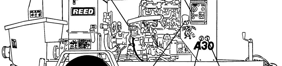
TRAILER MOUNTED PUMP MODEL A30 ILLUSTRATED PART MANUAL
|
|
|
- Austin Blankenship
- 5 years ago
- Views:
Transcription
1 TRAILER MOUNTED PUMP MODEL ILLUSTRATED PART MANUAL GROUP 00 FIGURE 00 REED TRAILER MOUNTED CONCRETE PUMP 03 MODEL ILLUSTRATED MANUAL CONTAINS THE FOLLOWING GROUPS AND FIGURES: GROUP 00 HOW TO USE MANUAL FIGURE 00 FIGURE 01 FIGURE 02 TABLE OF CONTENTS HOW TO USE MANUAL HOW TO ORDER GROUP 10 FINAL INSTALLATION FIGURE 00 FIGURE 01 FIGURE 02 TABLE OF CONTENTS FINAL INSTALLATION DECAL ASSEMBLY GROUP 20 HOPPER INSTALLATION FIGURE 00 FIGURE 01 FIGURE 02 TABLE OF CONTENTS HOPPER INSTALLATION HOPPER CLEAN OUT DOOR ASSEMBLY GROUP 30 TANK INSTALLATION FIGURE 00 FIGURE 01 TABLE OF CONTENTS TANK INSTALLATION GROUP 40 POWER TRAIN INSTALLATION FIGURE 00 FIGURE 01 FIGURE 02 FIGURE 03 TABLE OF CONTENTS POWER TRAIN INSTALLATION BATTERY MOUNTING ASSEMBLY HYDRAULIC PUMP ASSEMBLY GROUP 50 CONTROLS INSTALLATION FIGURE 00 FIGURE 01 FIGURE 02 FIGURE 03 FIGURE 04 TABLE OF CONTENTS CONTROLS INSTALLATION CONTROL BOX ASSEMBLY CABLE REMOTE CONTROL ASSEMBLY RADIO REMOTE CONTROL ASSEMBLY
2 TRAILER MOUNTED PUMP MODEL ILLUSTRATED PART MANUAL GROUP 00 FIGURE 00 PAGE 02 GROUP 60 PUMPING TRAIN INSTALLATION FIGURE 00 FIGURE 01 FIGURE 02 FIGURE 03 FIGURE 04 FIGURE 05 FIGURE 06 FIGURE 07 FIGURE 08 FIGURE 09 FIGURE 10 FIGURE 11 TABLE OF CONTENTS PUMPING TRAIN INSTALLATION SWING VALVE ASSEMBLY SWING RAM CYLINDER SUB-ASSEMBLY CONCRETE CYLINDER ASSEMBLY FLUSHBOX ASSEMBLY HYDRAULIC DRIVE CYLINDER ASSEMBLY LEFT HAND SIDE DRIVE CYLINDER SUB-ASSEMBLY RIGHT HAND SIDE DRIVE CYLINDER SUB-ASSEMBLY CONTROL WITH CARTRIDGE MANIFOLD ASSEMBLY REVERSE CIRCUIT PILOT SOLENOID VALVE ASSEMBLY MAIN CYCLING CIRCUIT PILOT SOLENOID VALVE ASSEMBLY GROUP 70 FRAME INSTALLATION FIGURE 00 FIGURE 01 FIGURE 02 FIGURE 03 FIGURE 04 TABLE OF CONTENTS FRAME INSTALLATION HUB AND BRAKE ASSEMBLY NON-OPERATOR SIDE ELECTRIC BRAKE ASSEMBLY OPERATOR SIDE ELECTRIC BRAKE ASSEMBLY GROUP 80 OPTIONAL INSTALLATION FIGURE 00 FIGURE 01 FIGURE 02 FIGURE 03 FIGURE 04 FIGURE 05 FIGURE 06 FIGURE 07 FIGURE 08 FIGURE 09 TABLE OF CONTENTS OPTIONAL INSTALLATION OPTIONAL TOOL KIT ASSEMBLY ACTUATOR BRAKES ASSEMBLY WATER PUMP INSTALLATION WATER PUMP CONTROL VALVE ASSEMBLY WATER PUMP MOTOR ASSEMBLY WATER PUMP ASSEMBLY NON-OPERATOR SIDE HYDRAULIC BRAKE ASSEMBLY OPERATOR SIDE HYDRAULIC BRAKE ASSEMBLY
3 TRAILER MOUNTED PUMP MODEL HOW TO USE PART MANUAL GROUP 00 FIGURE 01 I. PURPOSE This parts manual is prepared, issued and/or revised by REED Manufacturing, for the exclusive use of its customers and is intended for use in provisioning, requisitioning, storing and issuing replaceable REED trailer mounted pump model. The contents are proprietary to REED and are subject to change without notice. The use of any part of this document by any other person or persons or for any other purpose without the written consent of REED is expressly prohibited. In addition, REED expressly disclaims any and all responsibility arising in or any way related to such REED s prior written consent thereto. The parts number content of this document, arrangement and breakdown sequence of items is compatible with Military Standard (MS) and Air Transport Association Specification (ATA). II. GENERAL SYSTEM OF ASSEMBLY ORDER Detailed Parts List (Refer to Next Page) 1. This area refers to the corresponding illustration MODEL GROUP FIGURE PAGE A. MODEL shows which is REED s model number. B. GROUP should be divided with: 00 MODEL MANUAL 10 FINAL INSTALLATION 20 HOPPER INSTALLATION 30 TANK INSTALLATION 40 POWER TRAIN INSTALLATION 50 CONTROL INSTALLATION 60 PUMPING TRAIN INSTALLATION 70 FRAME INSTALLATION 80 OPTIONAL INSTALLATION C. FIGURE belong to the group. Please see page of contents and each group. D. PAGE numbers follow to the right of each figure number. 2. The ITEM NUMBER corresponds to the item number shown for the part in illustration. Parts with item number preceded by a dash (such as: -1, -5, -12 etc.) are not illustrated. 3. NUMBERS that carry a REED part number.


4 TRAILER MOUNTED PUMP MODEL HOW TO USE PART MANUAL GROUP 00 FIGURE 01 PAGE 02
5 TRAILER MOUNTED PUMP MODEL HOW TO USE PART MANUAL GROUP 00 FIGURE 01 PAGE DESCRIPTION A. The INDENTURE SYSTEM used in the parts list shows the relationship of one part to another. For a given item, the number of indentures depicts the relationship of the item to the components of the item as follows: Assembly (or Installation) Detail part of assembly Sub-assembly Attaching parts for sub-assembly Detail part of sub-assembly Sub-sub-assembly Attaching parts for sub-sub-assembly Detail part of sub-sub-assembly Sub-sub-sub-assembly Attaching parts of sub-sub-sub-assembly Detail part of sub-sub-sub-assembly B. See Group 60, Figure 02 For NHA Identifies the illustrated parts chapter location; indicates where the Next Higher Assembly (NHA) of the item shown. C. See Group 60, Figure 07 For DET Identifies the illustrated parts chapter location; indicates where the item and its Detailed Breakdown (DET) is shown. D. See Group 30, Figure 05 for REF or See Vendor Chapter For REF Identifies the illustrated parts chapter where the part is, and if listed and illustrated in Vendor Chapter. It is used as a cross-reference (REF). 5. QUANTITY A. Reference (REF) indicates the items that is listed previously in the Next Higher Assembly (NHA) and then again in this figure. B. As Required (A/R) indicates the parts that is used in a quantity as required. C. A number entry indicates the quantity of the part used in its next higher application. 6. Functionally related assemblies are illustrated in phantom ( ) but not listed on the detail parts list page.


6 TRAILER MOUNTED PUMP MODEL HOW TO ORDER 1. Always give serial number and model of REED trailer mounted concrete pump model. (Refer to each unit name plate shown below). NOTE: This manual is being released to cover unit starting with serial number to current production. Some components used on earlier units differ from current productions. Where this occurs, the part is identified by a serial number. GROUP 00 FIGURE Always specify part number and complete name of parts ordered. A. Turn to table of content in the desired Installation. Refer to main group in which part should be listed. B. Find title of figure in which the part should be shown. Note figure number.


7 TRAILER MOUNTED PUMP MODEL HOW TO ORDER GROUP 00 FIGURE 02 PAGE 02 C. Turn to corresponding page, find the group and figure. D. Check your required part and its attaching parts and match with illustration page. E. Refer to corresponding item number in the part list page. Part numbers are located in the part number column. F. When ordering variable or optional miscellaneous parts which are not found this in parts chapter, follow the above outlined procedure of how to order parts. 1). When applicable, give model and serial number of the component for which parts are desired. 2). In a specific, difficult to describe situation, a marked-up photograph or detailed sketch would be helpful.
8 TRAILER MOUNTED PUMP MODEL HOW TO ORDER GROUP 00 FIGURE 02 PAGE Do not designate quantity by set. State specifically how many parts are wanted. 4. Always give complete address and full shipping instructions. Specify shipping instructions, truck freight, air freight. United Parcel Service (UPS), or FedEx and DHL are available in designated areas. 5. TO ORDER A. BY MAIL Attention: Parts Department REED LLC Oaks Avenue Chino, CA B. BY FAX (909) C. BY PHONE (909) Parts return without authorization will not be accepted. If it is necessary to return parts for any reason, written authorization may be obtained from REED Parts Department, Chino, CA A Parts Return Authorization form is provided when REED deems its necessary to have the part returned for evaluation. The form is issued by the Warranty of Parts Department of REED. A. The form will be filled by REED unless requesting necessary information and you will receive a copy as well as shipping tag. B. Attach shipping tag to part insert return original invoice. C. Ship part to REED PREPAID. D. Part must be returned to REED within 30 days from date of authorization.
9 TRAILER MOUNTED PUMP MODEL GROUP 10 FINAL INSTALLATION GROUP 10 FIGURE 00 REED TRAILER MOUNTED CONCRETE PUMP 03 MODEL ILLUSTRATED MANUAL GROUP 10 FINAL INSTALLATION CONTAINS THE FOLLOWING FIGURES: FIGURE 00 FIGURE 01 FIGURE 02 TABLE OF CONTENTS FINAL INSTALLATION DECAL ASSEMBLY


10 FINAL INSTALLATION GROUP 10 FIGURE 01
11 FINAL INSTALLATION GROUP 10 FIGURE 01 PAGE 02 ITEM NO. REED S NO. DESCRIPTION QTY V03 Installation, Final Ref Installation, Hopper 1 (See Group 20, Figure 01 for DET) 3 BW43005 Installation, Hydraulic/Fuel Group 1 (See Group 30, Figure 01 for DET) 4 BW31021 Installation, Power Train Group 1 (See Group 40, Figure 01 for DET) Installation, Control 1 (See Group 50, Figure 01 for DET) Installation, Pumping Train 1 (See Group 60, Figure 01 for DET) Installation, Frame 1 (See Group 70, Figure 01 for DET) Installation, Optional 1 (See Group 80, Figure 01 for DET) 9 BW10121 Kit, A-SERIES Decal 1 (See Group 10, Figure 02 for DET)
12 DECAL ASSEMBLY GROUP 10 FIGURE 02


13 DECAL ASSEMBLY GROUP 10 FIGURE 02 PAGE 02
14 DECAL ASSEMBLY GROUP 10 FIGURE 02 PAGE 03
15 DECAL ASSEMBLY GROUP 10 FIGURE 02 PAGE 04

16 DECAL ASSEMBLY GROUP 10 FIGURE 02 PAGE 05
17 DECAL ASSEMBLY GROUP 10 FIGURE 02 PAGE 06
18 DECAL ASSEMBLY GROUP 10 FIGURE 02 PAGE 07
19 TRAILER MOUNTED PUMP MODEL GROUP 20 HOPPER INSTALLATION GROUP 20 FIGURE 00 REED TRAILER MOUNTED CONCRETE PUMP 03 MODEL ILLUSTRATED MANUAL GROUP 20 HOPPER INSTALLATION CONTAINS THE FOLLOWING FIGURES: FIGURE 00 FIGURE 01 FIGURE 02 TABLE OF CONTENTS HOPPER INSTALLATION HOPPER CLEAN OUT DOOR ASSEMBLY
20 HOPPER INSTALLATION GROUP 20 FIGURE 01
21 HOPPER INSTALLATION GROUP 20 FIGURE 01 PAGE 02 ITEM NO. REED S NO. DESCRIPTION Installation, Hopper Ref (See Group 10, Figure 01 for NHA) 2 BW10015 Weldment, Hopper Assembly, Clean Out Door 1 (See Group 20, Figure 02 for DET) 4 BW10042 Grate, Hopper Hinge, Grate A Decal, Warning Guard, Splash Decal, REED 4 ½ Inch Decal, ACPA Member Decal, Warning, Before Opening a Blocked Pipeline, Decal, Warning, Keep Hand Out of Hopper and Valve 2 QTY
22 HOPPER CLEAN OUT DOOR ASSEMBLY GROUP 20 FIGURE 02
23 HOPPER CLEAN OUT DOOR ASSEMBLY GROUP 20 FIGURE 02 PAGE 02 ITEM NO. REED S NO. DESCRIPTION Assembly, Rounded Clean Out Door Ref (See Group 20, Figure 01 and Figure 02 for NHA ) Bolt, Shoulder OPEN Door, Weldment Clean-Out 1 5 W A Cord, Hopper Door O-Ring 2.21 FT OPEN Block, RH Clean Out Door Block, LH Clean Out Door 1 9 Capscrew, Socket Head Plate, Seal Neck, Clean Out Door 1 QTY DASH (-) ITEM NOT ILLUSTRATED
24 TRAILER MOUNTED PUMP MODEL ILLUSTRATED MANUAL GROUP 20 FIGURE 03 THIS PAGE INTENTIONALLY LEFT BLANK.
25 TRAILER MOUNTED PUMP MODEL GROUP 30 TANK INSTALLATION GROUP 30 FIGURE 00 REED TRAILER MOUNTED CONCRETE PUMP 03 MODEL ILLUSTRATED MANUAL GROUP 30 HYDRAULIC TANK INSTALLATION CONTAINS THE FOLLOWING FIGURES: FIGURE 00 FIGURE 01 TABLE OF CONTENTS TANK INSTALLATION
26 TANK INSTALLATION GROUP 30 FIGURE 01
27 TANK INSTALLATION GROUP 30 FIGURE 01 PAGE 02
28 TANK INSTALLATION GROUP 30 FIGURE 01 PAGE 03
29 TANK INSTALLATION RETURN FILTER, HOUSING/ELEMENT/GAUGE GROUP 30 FIGURE 01 PAGE 04
30 TRAILER MOUNTED PUMP MODEL ILLUSTRATED MANUAL GROUP 30 FIGURE 02 THIS PAGE INTENTIONALLY LEFT BLANK.
31 TRAILER MOUNTED PUMP MODEL GROUP 40 POWER TRAIN INSTALLATION GROUP 40 FIGURE 00 REED TRAILER MOUNTED CONCRETE PUMP 03 MODEL ILLUSTRATED MANUAL GROUP 40 POWER TRAIN INSTALLATION CONTAINS THE FOLLOWING FIGURES: FIGURE 00 FIGURE 01 FIGURE 02 FIGURE 03 TABLE OF CONTENTS POWER TRAIN INSTALLATION BATTERY MOUNTING ASSEMBLY HYDRAULIC PUMP ASSEMBLY
32 POWER TRAIN INSTALLATION GROUP 40 FIGURE 01
33 POWER TRAIN INSTALLATION GROUP 40 FIGURE 01 PAGE 02 ITEM REED'S NO. NO. DESCRIPTION QTY Installation, Power Train 1 BW31021 (See Group 10, Figure 01 for NHA) Ref 2 BW10277 Cooler, Oil 1 3 BW10289 Spacer, Oil Cooler Mount 4 4 BW10278 Bracket, Oil Cooler Adaptor, MB-MJ Elbow, MB-MJ BW10280 Hose, 16GMV+ -20FJX-16FJX90S BW10281 Hose, 16GMV+ -20FJX-16FJX90S Flatwasher-3/8 USS 8-10 BW10246 Exhaust Safety Plate-Group 1-10A BW10179 Safety Plate, Exhaust Pipe Clamp Cap, Rain 1 Assembly, Battery Mounting (See Group 40, Figure 02 for DET) Clamp, Hose A Hose, 13ft FT Fuel 1 Assembly, Engine 1 16 BW (See Vendor Section, Figure 01 for REF) 17 BW10330 Element, Air Filter, Primary 1 18 BW10331 Element, Air Filter, Safety 1 19 BW10332 Filter, Oil 1 20 BW10333 Filter, Fuel Assembly, Hydraulic Gear Pump (See Group 40, Figure 03 for REF) -22 BW10319 Pump Drive Kit for BW10168 Hyd Pump Strap, Ground 1 Assembly, Engine Wiring Harness 1-24 BW10414 (See Schematic Section, Page 05 for REF) DASH (-) ITEM NOT ILLUSTRATED


34 BATTERY MOUNTING ASSEMBLY GROUP 40 FIGURE 02


35 BATTERY MOUNTING ASSEMBLY GROUP 40 FIGURE 02 PAGE 02
36 HYDRAULIC PUMP ASSEMBLY GROUP 40 FIGURE 03
37 HYDRAULIC PUMPS ASSEMBLY GROUP 40 FIGURE 03 PAGE 02 ITEM NO. REED S NO. DESCRIPTION BW10168 Assembly, Permco Hydraulic Pump (See Group 40, Figure 01 for NHA) 2 Bearing, Outboard (Optional) 1 3 Spacer 1 4 Cover, Shaft End 1 5 Bushing, Journal 6 6 Plate, Thrust 3 7 Set, Integral Gear 1 8 Pin, Dowel 6 9 Housing, Gear 2 10 Carrier, Bearing 1 11 Shaft, Connecting 1 12 Set, Connecting Gear 1 13 Cover, Port End 1 14 Washer, Flat (attaching parts) 4 15 Bolt, Hex (attaching parts) 4-16 BW10168-SK Kit, Seal 1 17 Ring, Spirolox Retaining 1 18 Seal, Shaft 1 19 Ring, Back Up 3 20 Ring, Seal 3 21 Gasket, Housing 4 DASH (-) ITEM NOT ILLUSTRATED QTY Ref
38 TRAILER MOUNTED PUMP - ILLUSTRATED MANUAL GROUP 40 FIGURE 04 THIS PAGE INTENTIONALLY LEFT BLANK.


39 TRAILER MOUNTED PUMP - GROUP 50 CONTROLS INSTALLATION GROUP 50 FIGURE 00 REED TRAILER MOUNTED CONCRETE PUMP 03 MODEL ILLUSTRATED MANUAL GROUP 50 CONTROLS INSTALLATION CONTAINS THE FOLLOWING FIGURES: FIGURE 00 FIGURE 01 FIGURE 02 FIGURE 03 FIGURE 04 TABLE OF CONTENTS CONTROLS INSTALLATION CONTROL BOX ASSEMBLY CABLE REMOTE CONTROL ASSEMBLY RADIO REMOTE CONTROL ASSEMBLY

40 CONTROL INSTALLATION GROUP 50 FIGURE 01
41 CONTROL INSTALLATION GROUP 50 FIGURE 01 PAGE 02 ITEM NO. REED S NO. DESCRIPTION Installation, Control Ref (See Group 10, Figure 01 for NHA) 2 BW10013 Assembly, Cable Remote Control 1 (See Group 50, Figure 03 for DET) 3 BW Assembly, Control Box 1 (See Group 50, Figure 03 for DET) Bumper, Control Box Gauge, Proximity Sensor Setting 1 6 BW10132 Radio Remote Control Kit-Kartech (Optional Item) 1 (See Group 50, Figure 04 for DET) 7 BW10188 Radio Remote Control Kit-Remtron (Optional Item) (See Group 50, Figure 04 for DET) Gauge, 6,000 PSI Hydraulic Gauge, 3,000 PSI Hydraulic Adapter, Minicheck Gauge 2-11 BW10318 Hose, 48 Inch-90 Degree Minicheck Horn, 12 V 1 DASH (-) ITEM NOT ILLUSTRATED QTY


42 CABLE REMOTE CONTROL ASSEMBLY GROUP 50 FIGURE 02
43 CABLE REMOTE CONTROL ASSEMBLY GROUP 50 FIGURE 02 PAGE 02 THIS GROUP 50, FIGURE 02, NUMBER BW10013, CABLE REMOTE CONTROL ASSEMBLY, DETAIL LIST IS NOT AVAILABLE THIS REVISION.
44 CONTROL BOX ASSEMBLY GROUP 50 FIGURE 03 PART NUMBER BW
45 CONTROL BOX ASSEMBLY GROUP 50 FIGURE 03 PAGE 02 ITEM NO. REED S DESCRIPTION NO. QTY BW CONTROL BOX ASSEMBLY 1 1 BW10208 E-Stop Light (Power Supply) 1 2 BW10214 Lens, Amber 1 3 BW10223 SPST Toggle Switch On-On 1 4 BW10215 Lens, Green 1 5 BW10205 SPDT Momentary Switch 1 6 BW10206 SPDT Momentary Switch 1 7 BW10207 SPST Toggle Switch 1 8 BW10207 SPST Toggle Switch 1 9 BW10206 SPDT Momentary Switch 1 10 BW10204 SW, Key Switch 1 11 BW10212 Hour Meter-Mini 1 12 BW x8x4 Steel CH Enclosure 1 13 BW10217 Connector, DRC12-24PA 1 14 BW10218 Connector, DT04-12PA-L012, 12 Pin EMT 1-15 BW10209 Mushroom Head Maintained Button 1 (Ref-BW10208 Red Light Housing) -16 BW10211 LGT, Mini Bayonet Red 1 (Ref-BW10208 and BW10209) -17 BW10213 Light Socket (Ref-BW10214 and BW10215) 5-18 BW10216 Light Bayonet 14V 5 (Ref-BW10213,BW10214 and BW10215) -19 BW10219 Connector 12 Pin, Gasket (Ref-BW10218) 1-20 BW10220 Connector 24in, Gasket (Ref-BW10217) 1 ITEM (-) NOT ILLUSTRATED
46 CONTROL BOX ASSEMBLY GROUP 50 FIGURE 03 PAGE 03
47 CONTROL BOX ASSEMBLY GROUP 50 FIGURE 03 PAGE 04 ITEM NO. REED S NO. DESCRIPTION BW10222 Relay, Diode Suppress 1 (Note: Same Part# For Items 1,2, &3) 2 BW10222 Relay, Diode Suppress 1 (Note: Same Part# For Items 1,2, &3) 3 BW10222 Relay, Diode Suppress 1 (Note: Same Part# For Items 1,2, &3) 4 BW10227 Fuse, Block GNG 6F 1 QTY


48 OPTIONAL RADIO REMOTE CONTROL ASSEMBLY GROUP 50 FIGURE 04 BW10247 DECAL BW10132 KAR-TECH RADIO REMOTE KIT BW10188 REMTRON RADIO REMOTE KIT 13
49 OPTIONAL RADIO REMOTE CONTROL ASSEMBLY GROUP 50 FIGURE 04 PAGE 02 ITEM NO. REED S NO. DESCRIPTION BW10196 Antenna Support 1 2 BW10194 Rod, Antenna 1 3 BW10201 Antenna Cable BW10012 Radio Remote Receiver-Kartech 1 5 BW10200 Plate Weldment, Rod Assembly Support 1 6 BW10202 Hair Pin 1 7 BW10011 Radio Remote Transmitter-Kartech 1 8 BW10192 Holster for Kartech Radio Transmitter 1 9 BW10190 Radio Remote Receiver-Remtron 1 10 BW10191 Holster Shoulder Strap for Remtron Transmitter 1 11 BW10189 Transmitter for Remtron Radio 1 12 NA Antenna-See BW NA Coax Cable-See BW Lanyard for BW BW10195 Tab, Antenna Support 1-16 BW10197 Tube, Rod Assembly Support 1-17 BW10198 Tube, Rod Assembly Support 1-18 BW10199 Plate, Rod Assembly Support 1-19 BW10200 Plate Weldment, Rod Assembly Support 1-20 BW10176 Bracket, Mounting-Remtron Radio QTY DASH (-) ITEM NOT ILLUSTRAT
50 TRAILER MOUNTED PUMP MODEL ILLUSTRATED MANUAL GROUP 50 FIGURE 05 THIS PAGE INTENTIONALLY LEFT BLANK.
51 TRAILER MOUNTED PUMP - GROUP 60 PUMPING TRAIN INSTALLATION GROUP 60 FIGURE 00 REED TRAILER MOUNTED CONCRETE PUMP 03 MODEL ILLUSTRATED MANUAL GROUP 60 PUMPING TRAIN INSTALLATION CONTAINS THE FOLLOWING FIGURES: FIGURE 00 TABLE OF CONTENTS FIGURE 01 PUMPING TRAIN INSTALLATION FIGURE 02 SWING VALVE ASSEMBLY FIGURE 03 SWING RAM CYLINDER SUB-ASSEMBLY FIGURE 04 CONCRETE CYLINDER ASSEMBLY FIGURE 05 FLUSHBOX ASSEMBLY FIGURE 06 HYDRAULIC DRIVE CYLINDER ASSEMBLY FIGURE 07 LEFT HAND SIDE DRIVE CYLINDER SUB-ASSEMBLY FIGURE 08 RIGHT HAND SIDE DRIVE CYLINDER SUB-ASSEMBLY FIGURE 09 CONTROL MANIFOLD WITH CARTRIDGE ASSEMBLY FIGURE 10 REVERSE CIRCUIT PILOTSOLENOID VALVE ASSEMBLY FIGURE 11 MAIN CYCLING CIRCUIT PILOT SOLENOID VALVE ASSEMBLY 2/11/08 EMY
52 PUMPING TRAIN INSTALLATION GROUP 60 FIGURE 01

53 PUMPING TRAIN INSTALLATION GROUP 60 FIGURE 01 PAGE 02
54 SWING VALVE ASSEMBLY GROUP 60 FIGURE 02


55 SWING VALVE ASSEMBLY GROUP 60 FIGURE 02 PAGE 02
56 SWING VALVE ASSEMBLY GROUP 60 FIGURE 02 PAGE 03 REVISION

57 SWING VALVE ASSEMBLY GROUP 60 FIGURE 02 PAGE 04
58 SWING RAM CYLINDER ASSEMBLY GROUP 60 FIGURE 03

59 SWING RAM CYLINDER ASSEMBLY GROUP 60 FIGURE 03 PAGE 02
60 CONCRETE CYLINDER ASSEMBLY GROUP 60 FIGURE 04
61 CONCRETE CYLINDER ASSEMBLY GROUP 60 FIGURE 04 PAGE 02 ITEM NO. REED S NO. DESCRIPTION BW23000 Assembly, Concrete Cylinder (See Group 60, Figure 01 for NHA) 2 BW10003 Cylinder, Concrete 2 3 BW10028 O-Ring, Concrete Cylinder 4 4 BW10018 Rod, Tie 6 5 BW10038 Spacer, Tie Rod 4 6 BW10016 Assembly, Tie Rod Spacer 1 7 Washer, Flat (attaching Parts) 6 8 Nut, Hex (attaching Parts) 6 9 Screw, Cap Coupling, Piston 2 11 BW10340 Adapter, 5 Inch Piston-Single Bolt 2 12 BW10032 Ring, 5 Inch Guide 2 13 BW10001 Cup, 5 Inch Piston 2 14 BW10342 Plate, 5 Inch Piston-Single Bolt 2 15 Washer, Star (attaching Parts) 2 16 Bolt, Hex (attaching Parts) 2 QTY Ref
62 FLUSH BOX ASSEMBLY GROUP 60 FIGURE 05


63 FLUSH BOX ASSEMBLY GROUP 60 FIGURE 05 PAGE 02
64 HYDRAULIC DRIVE CYLINDER ASSEMBLY GROUP 60 FIGURE 06 02/11/08 EMY
65 HYDRAULIC DRIVE CYLINDER ASSEMBLY GROUP 60 FIGURE 06 PAGE 02 02/11/08 EMY
66 LEFT HAND SIDE DRIVE CYLINDER ASSEMBLY GROUP 60 FIGURE 07 02/11/08 EMY
67 LEFT HAND SIDE DRIVE CYLINDER ASSEMBLY GROUP 60 FIGURE 07 PAGE 02 02/11/08 EMY
68 RIGHT HAND SIDE DRIVE CYLINDER ASSEMBLY GROUP 60 FIGURE 08
69 RIGHT HAND SIDE DRIVE CYLINDER ASSEMBLY GROUP 60 FIGURE 08 PAGE 02 02/11/08 EMY
70 CONTROL MANIFOLD WITH CARTRIDGE ASSEMBLY GROUP 60 FIGURE 09
71 CONTROL MANIFOLD WITH CARTRIDGE ASSEMBLY GROUP 60 FIGURE 09 PAGE 02
72 REVERSE CIRCUIT PILOT SOLENOID VALVE ASSEMBLY GROUP 60 FIGURE 10

73 REVERSE CIRCUIT PILOT SOLENOID VALVE ASSEMBLY GROUP 60 FIGURE 10 PAGE 02
74 MAIN CYCLING CIRCUIT PILOT SOLENOID VALVE ASSEMBLY GROUP 60 FIGURE 11

75 MAIN CYCLING CIRCUIT PILOT SOLENOID VALVE ASSEMBLY GROUP 60 FIGURE 11 PAGE 02
76 TRAILER MOUNTED PUM - ILLUSTRATED MANUAL GROUP 60 FIGURE 12 THIS PAGE INTENTIONALLY LEFT BLANK.


77 TRAILER MOUNTED PUMP - GROUP 70 FRAME INSTALLATION GROUP 70 FIGURE 00 REED TRAILER MOUNTED CONCRETE PUMP 03 MODEL ILLUSTRATED MANUAL GROUP 70 FRAME INSTALLATION CONTAINS THE FOLLOWING FIGURES: FIGURE 00 FIGURE 01 FIGURE 02 FIGURE 03 FIGURE 04 TABLE OF CONTENTS FRAME INSTALLATION HUB AND BRAKE ASSEMBLY NON-OPERATOR SIDE ELECTRIC BRAKE ASSEMBLY OPERATOR SIDE ELECTRIC BRAKE ASSEMBLY


78 FRAME INSTALLATION GROUP 70 FIGURE 01
79 FRAME INSTALLATION GROUP 70 FIGURE 01 PAGE 02 ITEM NO. REED S NO. DESCRIPTION Installation, Frame (See Group 10, Figure 01 for NHA) 2 BW45030 Group, Cover 1 3 BW10399 Cover, Engine Top 1 4 BW10400 Cover, Engine Front 1-5 BW41020 Group, Frame Kit, Break Away Connector, Chain Chain, 3/8 Proof Coil GR 30 Zinc 6 FT 1 9 BW10266 Engine Mount-Front (Yellow) 2 10 BW10270 Engine Mount-Rear (Green) 2 11 BW10404 Assembly, Frame Lunette, 3 Inch Eye 1 13 BW10099 Jack, Caster 1 14 BW10098 Jack 1 15 BW10169 Jack, Foot 1 16 BW10267 Fender Washer-3/4 ID 4 17 BW10398 Weldment, Frame 1 18 BW10095 Axle 1 19 BW10096 Assembly, Tire and Wheel Assembly, Hub and Brake 1 (See Group 70, Figure 02 for DET) -21 BW10180 Spacer, Axle Mount 2 22 BW10350 Weldment, Left Fender 1 23 BW10349 Weldment, Right Fender Light, Tail 2 25 BW10114 Weldment, Outrigger Outer Tube 2 26 BW10110 Weldment, Outrigger Inner Leg Pin, Outrigger Safety Lanyard, Q/R Pin Clamp, Loom Grommet, Trailer Clamp, Tube-Single Nut, Tee-Tube Clamp 10 DASH (-) ITEM NOT ILLUSTRATED QTY Ref
80 HUB AND BRAKE ASSEMBLY GROUP 70 FIGURE 02
81 HUB AND BRAKE ASSEMBLY GROUP 70 FIGURE 02 PAGE 02 ITEM NO. REED S NO. DESCRIPTION Assembly, Hub and Brake (Left And Right Side) Ref (See Group 70, Figure 01 for NHA) Seal, Double Lip Grease Bearing, Inner Race, Inner Bearing L Assembly, Non-Operator Side Electric Brake (Set) 1 (See Group 70, Figure 03 for DET) R Assembly, Operator Side Electric Brake (Set) (See Group 70, Figure 04 for DET) 1 7 Assembly, Drum And Hub 2 8 Stud, Wheel 12 9 Race, Outer Bearing 2 10 Bearing, Outer 2 11 Washer, Spindle 2 12 Nut, Spindle 2 13 Pin, Cotter 2 14 Cap, Dust 2 15 Nut, Wheel 12 QTY DASH (-) ITEM NOT ILLUSTRATED
82 NON OPERATOR SIDE ELECTRIC BRAKE ASSEMBLY GROUP 70 FIGURE 03


83 NON OPERATOR SIDE ELECTRIC BRAKE ASSEMBLY GROUP 70 FIGURE 03 PAGE 02
84 OPERATOR SIDE ELECTRIC BRAKE ASSEMBLY GROUP 70 FIGURE 04


85 OPERATOR SIDE ELECTRIC BRAKE ASSEMBLY GROUP 70 FIGURE 04 PAGE 02
86 TRAILER MOUNTED PUMP - ILLUSTRATED MANUAL GROUP 70 FIGURE 05 THIS PAGE INTENTIONALLY LEFT BLANK.

87 TRAILER MOUNTED PUMP - GROUP 80 OPTIONAL INSTALLATION GROUP 80 FIGURE 00 REED TRAILER MOUNTED CONCRETE PUMP 03 MODEL ILLUSTRATED MANUAL GROUP 80 OPTIONAL INSTALLATION CONTAINS THE FOLLOWING FIGURES: FIGURE 00 FIGURE 01 FIGURE 02 FIGURE 03 FIGURE 04 FIGURE 05 FIGURE 06 TABLE OF CONTENTS OPTIONAL INSTALLATION HOPPER VIBRATOR ASSEMBLY OPTIONAL TOOL KIT ASSEMBLY ACTUATOR-SURGE BRAKES ASSEMBLY NON-OPERATOR SIDE HYDRAULIC BRAKE ASSEMBLY OPERATOR SIDE HYDRAULIC BRAKE ASSEMBLY

88 OPTIONAL INSTALLATION GROUP 80 FIGURE 01


89 OPTIONAL INSTALLATION GROUP 80 FIGURE 01 PAGE 02
90 HOPPER VIBRATOR ASSEMBLY GROUP 80 FIGURE 02

91 HOPPER VIBRATOR ASSEMBLY GROUP 80 FIGURE 02 PAGE 02


92 OPTIONAL TOOL KIT ASSEMBLY GROUP 80 FIGURE 03


93 OPTIONAL TOOL KIT ASSEMBLY GROUP 80 FIGURE 03 PAGE 02

94 ACTUATOR-SURGE BRAKES ASSEMBLY GROUP 80 FIGURE 04 5/25/2006-emy
95 ACTUATOR-SURGE BRAKES ASSEMBLY GROUP 80 FIGURE 04 PAGE 02 5/25/06-emy
96 NON-OPERATOR SIDE HYDRAULIC BRAKE ASSEMBLY GROUP 80 FIGURE 05


97 NON-OPERATOR SIDE HYDRAULIC BRAKE ASSEMBLY GROUP 80 FIGURE 05 PAGE 02
98 OPERATOR SIDE HYDRAULIC BRAKE ASSEMBLY GROUP 80 FIGURE 06


99 OPERATOR SIDE HYDRAULIC BRAKE ASSEMBLY GROUP 80 FIGURE 06 PAGE 02
TRAILER MOUNTED PUMP MODEL A30HP ILLUSTRATED PART MANUAL TABLE OF CONTENTS HOW TO USE PARTS MANUAL HOW TO ORDER PARTS TABLE OF CONTENTS
 TRAILER MOUNTED PUMP MODEL ILLUSTRATED PART MANUAL GROUP 00 FIGURE 00 REED TRAILER MOUNTED CONCRETE PUMP MODEL ILLUSTRATED MANUAL CONTAINS THE FOLLOWING GROUPS AND FIGURES: GROUP 00 HOW TO USE MANUAL FIGURE
TRAILER MOUNTED PUMP MODEL B70 ILLUSTRATED PART MANUAL
 TRAILER MOUNTED PUMP MODEL ILLUSTRATED PART MANUAL GROUP 00 FIGURE 00 PAGE 01 REED TRAILER MOUNTED CONCRETE PUMP 05 MODEL B50 ILLUSTRATED MANUAL CONTAINS THE FOLLOWING GROUPS AND FIGURES: GROUP 00 HOW
B50 PARTS TRAILER MOUNTED PUMP MODEL B50 ILLUSTRATED PART MANUAL
 TRAILER MOUNTED PUMP MODEL ILLUSTRATED PART MANUAL GROUP 00 FIGURE 00 PAGE 01 REED TRAILER MOUNTED CONCRETE PUMP 05 MODEL ILLUSTRATED MANUAL CONTAINS THE FOLLOWING GROUPS AND FIGURES: GROUP 00 HOW TO USE
TRAILER MOUNTED PUMP MODEL B20 ILLUSTRATED PART MANUAL
 TRAILER MOUNTED PUMP MODEL ILLUSTRATED PART MANUAL GROUP 00 FIGURE 00 PAGE 01 MODEL HP SHOWN: STANDARD HOPPER WITH DUAL SHIFT SWING CYLINDERS REED TRAILER MOUNTED CONCRETE PUMP MODEL ILLUSTRATED MANUAL
TRAILER MOUNTED PUMP MODEL B20 ILLUSTRATED PART MANUAL
 TRAILER MOUNTED PUMP MODEL ILLUSTRATED PART MANUAL GROUP 00 FIGURE 00 PAGE 01 MODEL SHOWN: STANDARD HOPPER WITH MIXER REED TRAILER MOUNTED CONCRETE PUMP MODEL ILLUSTRATED MANUAL CONTAINS THE FOLLOWING
TRAILER MOUNTED PUMP MODEL C70 ILLUSTRATED PART MANUAL
 TRAILER MOUNTED PUMP MODEL ILLUSTRATED PART MANUAL GROUP 00 FIGURE 00 PAGE 01 REED TRAILER MOUNTED CONCRETE PUMP 02 MODEL ILLUSTRATED MANUAL CONTAINS THE FOLLOWING GROUPS AND FIGURES: GROUP 00 HOW TO USE
Hydrostatic Zero-Turn Commercial Riding Mower
 Hydrostatic Zero-Turn Commercial Riding Mower Turf Equipment MODEL 20HP Enforcer 44 22HP Enforcer 48 23HP Enforcer 54 ILLUSTRATED PARTS LIST TABLE OF CONTENTS Frame Assembly..................................
COMMERCIAL MOWERS PARTS MANUAL FOR: MODELS: ZKH52221 ZKH52251 ZKH61221 ZKH61251
 PARTS MANUAL FOR: COMMERCIAL MOWERS MODELS: ZKH52221 ZKH52251 ZKH61221 ZKH61251 FD KEES POWER EQUIPMENT, L.L.C. 700-800 PARK AVENUE BEATRICE, NEBRASKA, U.S.A. 68310 PRINTED IN USA MANUAL NO.-102935 REV.
Parts Manual for: MODELS / I.D. : / ZTH5223A / ZTH5225A / ZTH6125A
 Parts Manual for: MODELS / I.D. : 968999153 / ZTH5223A 968999154 / ZTH5225A 969999155 / ZTH6125A Husqvarna policy is to improve its products whenever it is possible and practical to do so. In an effort
MODELS: CC3730TE / CC3740TE
 DIAMOND P R O D U C T S CONCRETE SAW PARTS LIST MODELS: CC0TE / CC0TE February 00 Part #00 Table of Contents Pictorial Page Index....., Belt Guard Assembly... Controls Legend....... Belt Tensioner Assembly....
Parts Manual. Field-Pro Heavy Harrow Bar. Part Number H
 Parts Manual Field-Pro Heavy Harrow Bar Part Number H28542-04 IMPORTANT: ALL ITEMS ARE IDENTIFIED WITH A PART NUMBER. Some of the smaller parts such as bolts, nuts, washers, etc. are not all shown, however,
Parts Manual for MODELS: ZKH52222 ZKH52252 ZKH61252
 Parts Manual for MODELS: ZKH52222 ZKH52252 ZKH61252 Professional Quality Lawn Care Equipment since 1945 THIS MANUAL INCLUDES UPDATES ON PAGES 6,10, & 20. Yazoo/Kees Power Equipment policy is to improve
MMZ jr Hydrostatic Zero-Turn Riding Mower
 MMZ jr. Hydrostatic Zero-Turn Riding Mower MODEL ABM HP " Stamped Deck ILLUSTRATED PARTS LIST TABLE OF CONTENTS " Cutter Deck............................. and " Spindle Assembly.........................
PARTS MANUAL Rev A
 PARTS MANUAL 4000394 Table of Contents Part Index for Trailer --------------------------------------------- 2 Trailer Figure ----------------------------------------------------- 6 Trailer Figure 2 -----------------------------------------------------
CLASSIC 300D Kubota PARTS LIST FOR RETURN TO MAIN INDEX
 Illustration of Sub Assemblies Illustration of Sub Assemblies Illustration of Sub Assemblies Illustration of Sub Assemblies P-498 P-498 RETURN TO MAIN INDEX PARTS LIST FOR CLASSIC 300D Kubota P-498-A P-498-A
DX450 Red-D-Arc PARTS LIST FOR RETURN TO MAIN INDEX
 Illustration of Sub Assemblies Illustration of Sub Assemblies Illustration of Sub Assemblies Illustration of Sub Assemblies P-582 RETURN TO MAIN INDEX PARTS LIST FOR DX450 Red-D-Arc P-582 Index of Sub
D300K 3+3 SE KUBOTA PARTS LIST FOR RETURN TO MAIN INDEX
 Illustration of Sub Assemblies Illustration of Sub Assemblies Illustration of Sub Assemblies Illustration of Sub Assemblies P-737 P-737 RETURN TO MAIN INDEX PARTS LIST FOR P-737-A P-737-A ILLUSTRATION
Parts Manual SPDZTR 42 / SPDZTR 42 BF /
 Parts Manual SPDZTR 42 / 966657601 SPDZTR 42 BF / 966657701 Please read the operator s manual carefully and make sure you understand the instructions before using the machine. Gasoline containing up to
DIAMOND MODEL CC1300-XL P R O D U C T S CONCRETE SAW PARTS LIST. March Part#:
 DIAMOND P R O D U C T S CONCRETE SAW PARTS LIST MODEL CC1300-XL March 2007 Part#: 1800666 Intentionally Blank Table of Contents Description Page No. Frame Group....4-7 Engine Group 9 Horsepower Gas. 8
00238 R4 BODY, BOLT ON TORQUE TUBE PRODUCT LINE: 916/18 DATE: 12/4/06
 0 0 SH CAP SCREW, /-0 NC X / G PLAIN 00 NUT, NYLOCK, /-0 NC ZINC 00 HH CAP SCREW, /- NC X G ZINC 0 O-RING, -N0, -/ OD X / SECTION 00 WHEEL DRIVE MOTOR WITH KEY 0 00 GEAR, WHEEL DRIVE MOTOR 0 WASHER, /
8" STEEL HOPPER AUGER
 " STEEL HOPPER AUGER REF # PART # DESCRIPTION Sold By 1 01-00001 " or 10" HYDRAULIC MOTOR ea. 2 01-0000 O-RING ea. 000-01000 MANUAL FLOW CONTROL BLOCK c/w REF#2& ea. 010-00001 /1" x 2" SOCKET HEAD BOLT
How To Order Parts. Warranty
 How To Order Parts Warranty 1 2 Reporting Safety Defects Table Of Contents How To Order Parts... 1 Warranty... 1 Reporting Safety Defects... 2 Table Of Contents... 3 General Identification... 4 Warning
DIAMOND MODEL CC1900 EARLY ENTRY CONCRETE SAW PARTS LIST P R O D U C T S. (March 2012) Part #
 Part #") DIAMOND P R O D U C T S EARLY ENTRY CONCRETE SAW PARTS LIST MODEL CC1900 (March 2012) Part #1801617 (Intentionally Blank) TABLE OF CONTENTS Description Page No. Frame Assembly....4-5 Engine Assembly......6
DIAMOND P R O D U C T S EARLY ENTRY CONCRETE SAW PARTS LIST MODEL CC1900 (March 2012) Part #1801617 (Intentionally Blank) TABLE OF CONTENTS Description Page No. Frame Assembly....4-5 Engine Assembly......6
Parts Manual 881 Hay Hiker
 Parts Manual 881 Hay Hiker Part Number K20393P-06 IMPORTANT: ALL ITEMS ARE IDENTIFIED WITH A PART NUMBER. Some of the smaller parts such as bolts, nuts, washers, etc. are not all shown, however, the quantity
Parts Manual RZ4623 /
 Gasoline containing up to 10% ethanol (E10) is acceptable for use in this machine. The use of any gasoline exceeding 10% ethanol (E10) will void the product warranty. Parts Manual RZ4623 / 967009801 Please
535A. Main Components. Pipe and Bolt Threading Machine. Printed in U.S.A. Ridge Tool Company/Elyria, Ohio, U.S.A.
 Pipe and Bolt Threading Machine A Main Components 0 Screw, Button Head /" - 0 x /" () Washer, Flat /" ()" Top Cover 0 Base Bottom Cover Screw, Pan Head # - x " () Carriage Assembly 0 Front Support Bar
ZVKH52230 ZVKH61250 ZVKE61260 ZVKH61270 ZVKE72260 ZVKH72270 ZVKHL61230 ZVKW52250 ZVKW61230 ZVKW61250 MANUAL REV.
 Parts Manual Models ZVKH52230 ZVKH61250 ZVKE61260 ZVKH61270 ZVKE72260 ZVKH72270 ZVKHL61230 ZVKW52250 ZVKW61230 ZVKW61250 MANUAL 106149 REV. 04 (10/09/02) Model Number: Serial Number: Date of Purchase:
00278 R1 AXLE, FOR 1-1/8" FREE WHEEL HUBS
 00 ACTUATOR VALVE, O-RING PORTS 00 C-CLIP, /" 00 SPRING, VALVE SPOOL RETURN 00 COLLAR, / ID 00 WASHER, / USS, ZINC 00 HH CAP SCREW, /- NC X -/ G ZINC 0 FITTING, 0-- 00 O-RING, - FITTING 000-BO RELIEF VALVE,
Parts Manual 2200 Bale Hiker
 Parts Manual 2200 Bale Hiker Part Number K56202-02B IMPORTANT: ALL ITEMS ARE IDENTIFIED WITH A PART NUMBER. Some of the smaller parts such as bolts, nuts, washers, etc. are not all shown, however, the
Parts Manual TF Band Sawing Machine
 Parts Manual TF-2525 Serial No: 356-07283 to Band Sawing Machine MACHINE SPECIFICATIONS MODEL VOLTAGE CYCLE PHASE SERIAL NO. For your information and future reference, insert pertinent data concerning
HYDRAULIC CONTROL DETAILS PARTS LIST
 Always give model number, serial number and part number when ordering repair parts. HYDRAULIC CONTROL DETAILS PARTS LIST REF NO. PART NUMBER DESCRIPTION 1 101939 Hydraulic Tank 2 101940 Hydraulic Tank
CONCRETE SAW PARTS LIST
 CONCRETE SAW PARTS LIST MODEL CC00E- June 0 Part # 0 Table of Contents Pictorial Index.., 0hp Motor Assembly. Controls Legend... 0hp Belt Drive Assembly.. Notes 0hp Motor Assembly. Frame Upright Assembly.,
CHIPPER SHREDDER H524H, HS24W AHS24H, AHS24W Parts Catalog
 R Ingersoll CHIPPER SHREDDER H524H, HS24W AHS24H, AHS24W Parts Catalog 8-3291 HOME TRACTORS ATTACHMENTS PAINT GENERAL INFO ALPHABETICAL Body, Hopper and Shredder Hammers...5 Chipper Assembly...7 Trailer
DIAMOND CONCRETE SAW PARTS LIST MODEL CC1113-XL P R O D U C T S. June Part #
 DIAMOND P R O D U C T S CONCRETE SAW PARTS LIST MODEL CC1113-XL June 013 Part #10 TABLE OF CONTENTS Description Page No. Saw Assembly (Normal Cut).... - Saw Assembly (Up-Cut)...... - Gas Engine Assembly......
1822-I. Spindle Assembly. Pipe and Bolt Threading Machine. Ridge Tool Company/Elyria, Ohio, U.S.A. 2* 3 4 5* * *
 -I Pipe and Bolt Threading Machine Spindle Assembly * * * 0 * * * 0 * * 0* * * Rear Cover * Screw () * Washer () Top Cover w/clips (Includes,, ) * J Clip () Front Cover * Screw () Pivot Rod Support ()
/ ZTH5225KAA / ZTH6125KAA / ZTH6123KOLA / ZTH6127KOB / ZTH7227KOB For Serial No & Higher
 Parts Manual Models: 968999185 / ZTH5225KAA 968999186 / ZTH6125KAA 968999189 / ZTH6123KOLA 968999224 / ZTH6127KOB 968999225 / ZTH7227KOB For Serial No. 033600000 & Higher MANUAL 539109201 REV. 01 (09/15/04)
MANUAL REV. 03 (11/26/01)
") Parts Manual MANUAL 539105906 REV. 03 (11/26/01) Models: 968999175 / ZTH7226KOA 968999180 / ZTH5221KAA 968999181 / ZTH5223KAA 968999182 / ZTH5223KOA 968999183 / ZTH5223KOLA 968999184 / ZTH5225KOA 968999185
Parts Manual MANUAL 539105906 REV. 03 (11/26/01) Models: 968999175 / ZTH7226KOA 968999180 / ZTH5221KAA 968999181 / ZTH5223KAA 968999182 / ZTH5223KOA 968999183 / ZTH5223KOLA 968999184 / ZTH5225KOA 968999185
DIAMOND REAR PIVOT SAW PARTS LIST MODEL CC6160D P R O D U C T S. (September 2005) Part #
 Part #") DIAMOND P R O D U C T S REAR PIVOT SAW PARTS LIST MODEL CCD (September 00) Part #00 Intentionally Blank Table of Contents. Frame Upright Assembly.... Instrument Panel Assembly.... Speed Control Assembly....
DIAMOND P R O D U C T S REAR PIVOT SAW PARTS LIST MODEL CCD (September 00) Part #00 Intentionally Blank Table of Contents. Frame Upright Assembly.... Instrument Panel Assembly.... Speed Control Assembly....
Parts Manual. English
 Parts Manual WHF4817 / 966947005 WHF3617 / 966947008 Please read the operator s manual carefully and make sure you understand the instructions before using the machine. English 2009 HTC. All rights reserved.
HR24TS Rotary Rake. Serial Numbers less than Illustrated Parts Breakdown. Curtain & Guards, Front
 HRTS Rotary Rake Serial Numbers less than 00 Illustrated Parts Breakdown Page Page Page Page Page Page Page Page Page Page Page Page Tongue Front Frame Front Axle Curtain & Guards, Front Front Pivot Bridge
Di-Acro 18E Stylus Turret Punch Press
 OPERATOR S MANUAL & INSTRUCTIONS Di-Acro E Stylus Turret Punch Press Di-Acro, Incorporated PO Box 00 Canton, Ohio Progress Street N.E. Canton, Ohio 0 0-- 0--00 (fax) Revised 0/0 Sale or distribution of
HYDRAULIC MOWER AHRM4H, HRM48H Parts Catalog INDEX HOME TRACTOR ATTACHMENTS APPLICATION CHART
 R Ingersoll HYDRAULIC MOWER AHRM4H, HRM48H Parts Catalog 8-3091 HOME TRACTORS ATTACHMENTS PAINT GENERAL INFO INDEX Deck. Belt and Idler Pulley...5 Mounting Bracket...7 Rear Wheels...7 Hydraulic Drive...9-13
PARTS LIST COMMANDER 20 VAC-TRAC COMMANDER 27 VAC-TRAC FH 541V
 PARTS LIST COMMANDER 20 VAC-TRAC COMMANDER 27 VAC-TRAC FH 541V UPPER ASSEMBLY 101 6190481 THROTTLE CABLE FOR MODELS WITH ADDITIONAL CHOKE CABLE 1 101 6190751 THROTTLE CABLE FOR MODELS WITH OUT ADDITIONAL
Parts Catalog Collector 34 Model Battery
 Parts Catalog Table of Contents Side broom cpl. part 1 (97104618-1 6404-20)... 4 Side broom cpl. part 2 (97104618-2)... 6 Frame - Wheels (97104566)... 8 Covering B (97104855)... 10 Travel drive, part 1
Coolant Tank Screen Leg Idle End Lockwasher 64 B-015B Leg Drive End Machine Screw 1/4-20 x 3/4 Round Head
 Always give model number, serial number and part number when ordering repair parts. BED, COOLANT & DASH POT PARTS LIST (Cont'd.) REF NO. PART NUMBER DESCRIPTION 19 B-077 Vise Slide Block 20 B-045 Vise
Precision Split Parts Manual
 Precision Split Parts Manual Model 917001 7-Ton Log Splitter 0860400 /09 Printed in USA THE MANUAL Before you operate your unit, carefully and completely read manuals supplied with the unit. The contents
GP ONE SPLIT DECK 9/4/2012 COPYRIGHT 6/10/10 ALL RIGHTS RESERVED
 GP ONE SPLIT DECK PAGE G & P ONE GRINER SPLIT DECK SUB ASSEMBLY PARTS BREAK DOWN 4 2 24 20 2 6 0 36 24 7 27 2 2 25 3 32 2 24 28 24 8 7 24 5 2 25 2 20 2 4 3 2 34 5 26 22 2 27 35 22 3 30 6 9 29 8 29 2 9
PARTS LIST CHARGER 2716 DB
 PARTS LIST CHARGER 2716 DB 1 ITEM PART NO. DESCRIPTION QTY. 101 6495381 LEFT OUTER BEARING / PIVOT MOUNT 1 102 9121450 5/16-18 HEX NUT WITH NY-LOK INSERT - PACK OF 5 4 103 9121210 1/4-20 X 5/8 HEX BOLT
 Parts Manual for: MODELS / I.D. : 968999150 / ZTH4217A Husqvarna policy is to improve its products whenever it is possible and practical to do so. In an effort to keep pace with changes in technology,
Illustrated Parts Manual
 Illustrated Parts Manual Mustang Series RZT TROY-BILT LLC, P.O. BOX CLEVELAND, OHIO -00 Printed In USA Form No. -0 (December, 0) To The Owner Thank You Thank you for purchasing an MTD Zero-Turn Tractor.
Precision Split Parts Manual
 Precision Split Parts Manual Models 9700 7-Ton Log Splitter 9700 -Ton Log Splitter 086000B /09 Printed in USA THE MANUAL Before you operate your unit, carefully and completely read manuals supplied with
Operating Instructions and Parts Manual 5-ft. Radial Arm Drill Press Models J-1600R, J-1600R-4
 Operating Instructions and Parts Manual 5-ft. Radial Arm Drill Press Models J-1600R, J-1600R-4 JET 427 New Sanford Road LaVergne, Tennessee 37086 Part No. M-320038 Ph.: 800-274-6848 Revision H 01/2016
Parts Manual Ram Ultra 52, 25 KOH / Ram Ultra 61, 25 KOH / Ram Ultra 72, 27 KOH / Ram Ultra 52, 25 KOH BF /
 Parts Manual Ram Ultra 52, 25 KOH / 998501 Ram Ultra 1, 25 KOH / 9985401 Ram Ultra 72, 27 KOH / 98999724 Ram Ultra 52, 25 KOH BF / 998502 Ram Ultra 1, 25 KOH BF / 9985402 Ram Ultra 72, 27 KOH BF / 9899977
CONCRETE SAW PARTS LIST
 CONCRETE SAW PARTS LIST MODEL CC Wisconsin Fuel Injected (April 0) Part # 00 WARNING The engine exhaust from this product Contains chemicals known to the State of California to cause cancer, birth defects
PARTS CATALOG FRONT WHEEL DRIVE FOR JOHN DEERE 6100 & WHEEL SPRAYERS
 PARTS CATALOG FRONT WHEEL DRIVE FOR JOHN DEERE 6100 & 6500 3 WHEEL SPRAYERS MUD HOG MODEL NUMBERS JD6500-13.5-16.1 I3 Tire (Export) JD65003-12.5L-15 I3 Tire TUTHILL Transport Technologies Brookston Indiana
PARTS MANUAL. SERIAL NO: to BAND SAWING MACHINE
 PARTS MANUAL MODEL: TF-2025NC SERIAL NO: 541-98101 to BAND SAWING MACHINE MACHINE SPECIFICATIONS MODEL VOLTAGE CYCLE PHASE SERIAL NO. For your information and future reference, insert pertinent data concerning
Parts Manual RZ4221 BF /
 Gasoline containing up to 10% ethanol (E10) is acceptable for use in this machine. The use of any gasoline exceeding 10% ethanol (E10) will void the product warranty. Parts Manual RZ4221 BF / 9676101 Please
CM-1258Y-SD Concrete Mixer
 Form No. 3421-382 Rev A CM-1258Y-SD Concrete Mixer Model No. 68011 Serial No. 402000000 and Up Register at www.toro.com. Original Instructions (EN) *3421-382* A Ordering Replacement Parts To order replacement
Parts Manual SPEEDZTR 42SE /
 Parts Manual SPEEDZTR 42SE / 96667602 Please read the operator s manual carefully and make sure you understand the instructions before using the machine. Gasoline containing up to 10% ethanol (E10) is
CONCRETE SAW PARTS LIST
 CONCRETE SAW PARTS LIST MODEL CC00XL ELECTRIC & HYDRAULIC UNITS August, 0 Part # 0 Table of Contents Common Parts.. Front Axle Assembly... Rear Axle Assembly... Transmission Assembly... Blade Shaft Assembly
Parts Manual. Ultra 52 / Ultra 52 BF / Ultra 61 / Ultra 61BF /
 Parts Manual Ultra 52 / 966690601 Ultra 52 BF / 966690602 Ultra 61 / 966611801 Ultra 61BF / 966611802 Please read the operator s manual carefully and make sure you understand the instructions before using
CONCRETE SAW PARTS LIST
 CONCRETE SAW PARTS LIST MODEL CC00 Electric/Hydraulic April, 0 Part # Blade / Engine Speed (RPM) Chart Model CC00 Concrete Saw CAUTION: Do not exceed Bladeshaft speed (RPM) shown for each blade size. Excessive
Parts Manual RZ4222TF BF /
 Gasoline containing up to 10% ethanol (E10) is acceptable for use in this machine. The use of any gasoline exceeding 10% ethanol (E10) will void the product warranty. Parts Manual RZ4222TF BF / 96703601
MANUAL REV. 09 (04/20/06)
") Parts Manual MANUAL 539105906 REV. 09 (04/20/06) Models: 968999175 / ZTH7226KOA 968999180 / ZTH5221KAA 968999181 / ZTH5223KAA 968999182 / ZTH5223KOA 968999183 / ZTH5223KOLA 968999184 / ZTH5225KOA 968999185
Parts Manual MANUAL 539105906 REV. 09 (04/20/06) Models: 968999175 / ZTH7226KOA 968999180 / ZTH5221KAA 968999181 / ZTH5223KAA 968999182 / ZTH5223KOA 968999183 / ZTH5223KOLA 968999184 / ZTH5225KOA 968999185
Visual Guide. Balloons match the sections. - iii. Components & Parts Catalogue
 Balloons match the sections. Visual Guide - iii - iv - Components & Parts Catalogue Table of contents 1. Frame assembly... 1 1.1. Bumper Step Furnishings (Aluminium Checker)... 3 1.2. Sliding Cover assembly...
Parts Manual. Model: / WHF / WHF5219 MANUAL NO REV. 01 (09/15/04)
") Parts Manual Model: 685 / WHF4817 6853 / WHF51 MANUAL NO. 531586 REV. 01 (0//04) MODEL NUMBER SERIAL NUMBER DATE PURCHASED DEALER ADDRESS NOTES: 004 Husqvarna. All rights reserved. Beatrice, NE. Printed
Parts Manual Model: 685 / WHF4817 6853 / WHF51 MANUAL NO. 531586 REV. 01 (0//04) MODEL NUMBER SERIAL NUMBER DATE PURCHASED DEALER ADDRESS NOTES: 004 Husqvarna. All rights reserved. Beatrice, NE. Printed
Parts Manual. Please read the operator s manual carefully and make sure you understand the instructions before using the machine.
 Parts Manual SPDZTR 42 / 966657601 SPDZTR 42 BF / 966657701 SPDZTR 46 / 966657801 SPDZTR 42 CA / 966657901 SPDZTR 46 BF / 966658001 SPDZTR 48 / 966698601 SPDZTR 54 / 966658201 SPDZTR 54 / 966658301 SPDZTR
JARVIS. Model25CL-4,5,6 Hock Cutter and Loin Dropper. 25CL--5 Front Legs and Horns. 25CL--4 Hind Legs and Horns. 25CL--6 Loins
 Model25CL-4,5,6 Hock Cutter and Loin Dropper 25CL--4 Hind Legs and Horns 25CL--5 Front Legs and Horns 25CL--6 Loins EQUIPMENT SELECTION... Ordering No. TABLE OF CONTENTS... Page 25CL--4... 4025007 25CL--5...
Illustrated Pats List
 Illustrated Pats List Automatic Lawn Tractor Models 0 0 0 Model 0 Shown IMPORTANT: READ SAFETY RULES AND INSTRUCTIONS CAREFULLY Warning: This unit is equipped with an internal combustion engine and should
/ iz4218kaa / iz4818kaa / iz4821kaa / iz5223kaa / iz5223koa MANUAL NO REV.
 Parts manual Models: 6804 / iz418kaa 6805 / iz4818kaa 6806 / iz481kaa 6807 / iz53kaa 6808 / iz53koa MANUAL NO. 531070 REV. 05 (08/18/04) MODEL NUMBER SERIAL NUMBER DATE PURCHASED DEALER ADDRESS NOTES:
Illustrated Parts: Model 853
 Illustrated Parts: Model 853 BCS America LLC 5001 N Lagoon Ave Portland, OR 97217 Revised 09/20/2017 www.bcsamerica.com Phone: 800-543-1040 Fax: 800-777-7069 Bumper Accessories ------ - 823956 01.00 800.010-01.3
Promaster 260Z & 250Z
 Promaster 0Z & 0Z Parts Manual Models 0-0Z 00-0Z 0-0Z 0-0Z 0-0Z 0-0Z 0-0Z 0-0Z 000A /00 Supercedes 000 Printed in USA THE MANUAL Before you operate your unit, carefully and completely read manuals supplied
2008 HTC. All rights reserved. Beatrice, NE. Printed in U.S.A.
 Parts Manual LZ22 / 9687901 LZ227 / 968999674 LZ60 / 96899967 LZ7230 / 968999676 LZ6127 / 968999709 Please read the operator s manual carefully and make sure you understand the instructions before using
Walk-Behind Lawn Mowers
 Walk-Behind Lawn Mowers Parts Manual Models 2 - PRO21SCH 12 - LM21 1 - LM21S 1 - LM21SW 1 - LM21S 11 - PRO21SCH 0 - LM21SW - LM21S - LM21SW 5 - LM21S - LM21SW 0700 /0 Printed in USA THE MANUAL Before you
Parts Catalog. S-Series Slicer Smart Manual SG13. Model:
 , 07 99507 ECN 065 Parts Catalog S-Series Slicer Smart Manual Model: SG SG 0/0/07 Rev. G IMPORTANT! TO EXPEDITE SHIPMENT OF PARTS, ALWAYS SPECIFY MODEL, REV, PART NUMBER, AND SERIAL NUMBER OF UNIT. GLOBE
Parts Catalog Collector 34 Model Gasoline
 Parts Catalog Table of Contents Side broom cpl. part 1 (97104618-1 6404-10)... 4 Side broom cpl. part 2 (97104618-2)... 6 Frame - Wheels (97104566)... 8 Covering V (97104640)... 10 Travel drive, part 1
CONCRETE SAW PARTS LIST
 CONCRETE SAW PARTS LIST MODEL CCXL-EE December 01 Part # 1 Intentionally Blank Table of Contents Description Page No. Frame Assembly... Carriage Assembly Motor Assembly.... Blade Shaft Assembly... Spring
WX630 Trailer Log Splitter Parts Manual. Starting with S/N & After
 WX630 Trailer Log Splitter Parts Manual Starting with S/N 3000 & After Foreword EMB Mfg. has prepared this parts manual to assist customers in ordering quality OEM replacement parts. Proper and regular
M-5 PRO CORE BORE PARTS LIST DRILLING MACHINE. (March 2017) Part #
 Part #") M- PRO CORE BORE DRILLING MACHINE PARTS LIST (March 07) Part #809 Table of Contents Description Page No. Carriage Assembly....... - Combo Base Assembly....... - 7 Anchor Base Assembly........8 Anchor
M- PRO CORE BORE DRILLING MACHINE PARTS LIST (March 07) Part #809 Table of Contents Description Page No. Carriage Assembly....... - Combo Base Assembly....... - 7 Anchor Base Assembly........8 Anchor
SELF-PROPELLED SCISSOR LIFTS PARTS MANUAL. ( For JCPT0807HD / JCPT0807DC ) WARNING
 WARNING") SELF-PROPELLED SCISSOR LIFTS PARTS MANUAL ( For JCPT0807HD / JCPT0807DC ) WARNING THE MANUFACTURER SHALL NOT BE HELD LIABLE IN CASE OF FAULTS OR ACCIDENTS DUE TO NEGLIGENCE, INCAPACITY, INSTALLATION BY
SELF-PROPELLED SCISSOR LIFTS PARTS MANUAL ( For JCPT0807HD / JCPT0807DC ) WARNING THE MANUFACTURER SHALL NOT BE HELD LIABLE IN CASE OF FAULTS OR ACCIDENTS DUE TO NEGLIGENCE, INCAPACITY, INSTALLATION BY
PARTS LIST: Air Control Assembly (1632 Sander)
") PARTS LIST: Air Control Assembly (1632 Sander) 1 6293482 Filter... 1 2 6293483 Solenoid Valve... 1 3 6293484 Brake Cylinder... 1 4 6293485 Multi-Hole Connector... 1 5 6293486 Air Valve... 1 6 6293487 Air
PARTS LIST: Air Control Assembly (1632 Sander) 1 6293482 Filter... 1 2 6293483 Solenoid Valve... 1 3 6293484 Brake Cylinder... 1 4 6293485 Multi-Hole Connector... 1 5 6293486 Air Valve... 1 6 6293487 Air
Parts Manual RZ5426 /
 Gasoline containing up to 10% ethanol (E10) is acceptable for use in this machine. The use of any gasoline exceeding 10% ethanol (E10) will void the product warranty. Parts Manual RZ5426 / 967003606 Please
CONCRETE SAW PARTS LIST
 CONCRETE SAW PARTS LIST MODELS: CCDD CCDD- May 0 Part # 00 CC Single Speed Saw: CC- Speed Saw: Table of Contents Pictorial Page Index.., Air Intake Assembly, Controls Legend... Fan Assembly.. Quick Reference
For Serial No & Higher MANUAL NO REV. 04 (09/15/04)
") Parts manual Models: 606 / iz1kaa 60 / iz53kaa 60 / iz53koa 6 / iz1skaa 630 / iz1skaa 631 / iz1kaa 635 / iz613kaa For Serial No. 033600000 & Higher MANUAL NO. 53106 REV. 0 (0/15/0) MODEL NUMBER SERIAL
Parts manual Models: 606 / iz1kaa 60 / iz53kaa 60 / iz53koa 6 / iz1skaa 630 / iz1skaa 631 / iz1kaa 635 / iz613kaa For Serial No. 033600000 & Higher MANUAL NO. 53106 REV. 0 (0/15/0) MODEL NUMBER SERIAL
PARTS LIST FOR RETURN TO MAIN INDEX
 Illustration of Sub Assemblies Illustration of Sub Assemblies Illustration of Sub Assemblies Illustration of Sub Assemblies P-543 P-543 RETURN TO MAIN INDEX PARTS LIST FOR ! P-543-A P-543-A 1 ILLUSTRATION
S/N 2E9US1110DS058012
 Z905 BXMT Chipper-Shredder S/N E9US9AS05008 to E9USFS00 BXMT8su Chipper-Shredder S/N E9US0DS0580 to E9USFS05805 Parts Manual Foreword EMB Mfg. has prepared this parts manual to assist customers in ordering
When you need spare parts or support in service questions, warranty issues, etc., please consult the following professional: Engine
 Parts Manual EZC4824 / 658801 EZ4824K / 6588001 EZ4824 / 65880401 EZ5221 / 65880501 EZ5224 / 65880601 EZ5226 / 65201 EZ6124 / 65880701 Please read the operator s manual carefully and make sure you understand
Operating Instructions and Parts Manual. 10 x 16 Horizontal Band Saw Models J-7020, J-7040
 Operating Instructions and Parts Manual 10 x 16 Horizontal Band Saw Models J-7020, J-7040 JET 427 New Sanford Road LaVergne, Tennessee 37086 Part No. M-414472 Ph.: 800-274-6848 Revision C2 03/2014 www.jettools.com
Parts Manual SPEEDZTR 44 / SPEEDZTR 46 / SPEEDZTR 54 / SPEEDZTR 36 / SPEEDZTR 44 / SPEEDZTR 48 /
 Parts Manual SPEEDZTR / 6501 SPEEDZTR 6 / 65001 SPEEDZTR 5 / 651 SPEEDZTR 36 / 6501 SPEEDZTR / 65301 SPEEDZTR / 6501 Please read the operator s manual carefully and make sure you understand the instructions
Parts Manual SPEEDZTR 42 / SPEEDZTR 42BF / SPEEDZTR 46BF / SPEEDZTR 48BF / SPEEDZTR 54BF /
 Parts Manual SPEEDZTR 42 / 6603801 SPEEDZTR 42BF / 66054201 SPEEDZTR 46BF / 658831 SPEEDZTR 48BF / 65883501 SPEEDZTR 54BF / 65883201 Please read the operator s manual carefully and make sure you understand
PARTS LIST FOR MODEL 7000 SERIES - 17/46
 ITEM PARTS LIST FOR MODEL 7000 SERIES - 17/46 1 Rotor 3 Housing 1 4 End Plate 6 Drive End Cover 1 7 Free End Cover 1 8 Timing Gear Set 1 9 Bearing, Drive End 10 Bearing, Free End 1 Lip Seal, Viton 4 13
PARTS MANUAL.
 www.mkdiamond.com MK-00 Electric Block Saw PARTS MANUAL MODELS P/N MK-00S Block Saw Single-Phase 0Hz/0V 0 MK-00T Block Saw -Phase 0Hz/0V 0 MK-00T Block Saw -Phase 0Hz/0V 07 Revision 00 0.08 Manual Part#
ST927E Spare Parts
 ST927E 1.1997 Spare Parts ELECTRIC START ASSEMBLY 8 9 7 6 ENGINE 6 601 00 15-88 MOTOR, STARTER 7 601 00 15-89 SCREW, 1/4-20X.50 8 601 00 15-90 SCREW, #6-32X2.50 9 601 00 15-91 CORD, STARTER 10 601 00 21-61
APPLICATION CHART. Tractor Model * Wood Splitter HOME TRACTORS ATTACHMENTS INDEX
 R Ingersoll HOME WOOD SPLITTER J31, K31 AHSHD, HSHD, J32, K32, J32 J34, K34, L34 AHSWD, HSWD, K36 Parts Catalog 8-2052 NOTE: This Catalog replaces Catalog 8-2051 TRACTORS ATTACHMENTS INDEX PAINT GENERAL
Parts Catalog. S-Series Slicer Manual Frozen Option S13. Model:
 , 07 995 ECN 08 Parts Catalog S S-Series Slicer Manual Frozen Option Model: S 05/0/07 Rev. G IMPORTANT! TO EXPEDITE SHIPMENT OF PARTS, ALWAYS SPECIFY MODEL, REV, PART NUMBER, AND SERIAL NUMBER OF UNIT.
Main Drive Components
 Pipe and Bolt Threading Machine Main Drive Components 0 0 Rear Centering Head Centering Jaw Set Spiral Pins () 00 Centering Scroll Retaining Ring 0 Rear Bearing 0 Oil Ball Valve () # - x / Screw Motor
STONE EXTREME /29/2013 PART NUMBER
 STONE EXTREME 700 PART NUMBER 005 STONEKOR LLC -800-6-059 customerservice@stonekor.com www.stonekor.com 9 0 6 0 6 5 0 8 6 5 7 STONE EXTREME 700 5 5 7 7 6 0 MACHINE: 005 5 5 8 7 8 9 0 9 STONEKOR LLC -800-6-059
Parts Catalog Admiral 28 Cylindrical Scrubber
 Parts Catalog Table of Contents Front bounce protection (97116834)... 4 Wheel suspension (97103725)... 6 Chassis (97115422)... 8 (97114763)... 10 Steering (97073738)... 12 Seat bracket (97118616)... 14
Parts Manual RZ4824F /
 Gasoline containing up to 10% ethanol (E10) is acceptable for use in this machine. The use of any gasoline exceeding 10% ethanol (E10) will void the product warranty. Parts Manual RZ4824F / 967003802 Please
Parts Manual 900 Hay Hiker
 Parts Manual 900 Hay Hiker Part Number K49078-04 IMPORTANT: ALL ITEMS ARE IDENTIFIED WITH A PART NUMBER. Some of the smaller parts such as bolts, nuts, washers, etc. are not all shown, however, the quantity