These below wires are the input RCA Plugs.
|
|
|
- Lewis Baker
- 5 years ago
- Views:
Transcription

1 IMPORTANT: The information contained within this document is intended to offer some basic guidelines for the most common installations. More complex audio systems should be installed by a competent professional. Motorcycle Tunes is NOT responsible for any damage to your bike or equipment caused by improper installation or faulty equipment. None of the below input wires will be used. You will need to cap the ends of each individual wire using the included clear crimp wire caps. These below wires are the input RCA Plugs. IMPORTANT: The information contained within this document is intended to offer some basic guidelines for the most common installations. More complex audio systems should be installed by a competent professional. Motorcycle Tunes is NOT responsible for any damage to your bike or equipment caused by improper installation or faulty equipment. CAUTION: Amplifier is NOT waterproof. Install it under the seat, saddlebag, travel trunk, fork bag, or in our amplifier bag. CAUTION: DO NOT INSTALL THE FUSE FOR THE AMPLIFIER, UNTIL INSTRUCTED TO DO SO. CAUTION: The Clarion amplifier has a built in heavy duty heat sink, designed to keep the amplifier cool and prevent heat robbing distortions from running the music. This allows the amplifier to be installed in tight locations without heat issues.
2 Begin by planning on where you are going to mount the speakers and amplifier. Keep in mind the amp needs a minimum of 1 around it for proper cooling Plan the wire routing; you don t want it around the exhaust or for it to rub. You also don t want to route the power cable next to the audio input cable, because this can add noise to the system. Amplifier Power There are 3 Power Wires (1 Power Red Wire, 1 Remote Turn On Blue Wire, and 1 Ground Black Wire) Step 1: Red Wire (B+) - This is the Red wire with the Fuse box and ring terminal. Hook bare end to the +12V hookup on the amplifier and the terminal ring to the positive battery post. Step 2: Black Wire (Ground) This is the Black wire with the ring terminal on the end. Hook the bare end to the GROUND terminal on the amplifier, and hook the terminal end to the negative battery terminal of the motorcycle or to the frame of the motorcycle. GETTNG A GOOD GROUND IS VERY IMPORTANT, BECAUSE 99% OF NOISE ENTERS THROUGH THE GROUND OF A SYSTEM. Trim the length of the ground wire, keep it short as possible, Step 3: Blue Wire (Remote Turn On Wire) This is the wire that turns the power to the amplifier on and off. This wire is located on the Speaker Output plug of the amplifier. If you ordered the Bluetooth edition, The Bluetooth Blue wire will hook Remote Turn on wire on the amplifier (see attached Bluetooth instructions for Pairing) The Bluetooth Red wire will hook to a switched and fused power supply, so that it turns on/off with the key The Bluetooth Black wire will hook to the negative battery terminal, or to the frame of the bike. If you did not get the Bluetooth edition, this blue wire can be used with the included t-tap, or the plug can be cut off and the now bare end should be wired to a switched and fused 12v power source on your bike so that it turns on/off with the key. You can use a test light to find a wire that turns on/off with your key, such as a headlight wire, or you can add a mechanical switch inline with a 12 volt source to activate the amplifier. Run the bare end up to where you are going to mount the amplifier. Speaker Mounting Step 4: Mounting the Speaker Clamps: Get an idea where you want to mount the speakers. Mount the clamps to your bars. There will be a gap on the clamps that will tighten up when the speakers are installed.. Important: Make sure the speakers will not interfere with your steering, or gauges. Step 5: Mounting the Speakers: Mount each speaker to the clamp and make sure they are secured, but do not apply too much torque to the nut. The bottom mounting bolt is chromed stainless steel. Use a pair of vice grips on the end of the clamps to slightly pull them together, that way when you put the speaker mounting bolt through the clamps, you will have more room to tighten the nut a few turns by hand. This will ensure the nut has good thread before you tighten it by wrench, and will prevent the nut from cross threading and seizing up. The 3-Piece clamps will NOT close all the way, just tighten them snuggly. IMPORTANT The speaker mounting bolt is chromed stainless steel, and the treads on this bolt can be stripped easily if the nut tightened too much, or if the nut is not perfectly aligned before tightening. When you mount the speakers to the clamps use care, or you can damage the thread. Run the speaker wires down to where you are going to mount the amplifier. You may want to run the Audio Adapter Cable at this time a well. Amplifier Speaker Output Plug This is a small 4 prong plug, with 4 short speaker wires on it. Step 6: Hooking up the speaker wires to the Amplifier Speaker Output Plug. 2 Speaker Setup Left Chrome Speaker Red to the Solid White Left Chrome Speaker Black to Gray/Black Right Chrome Speaker Red to Solid Green Right Chrome Speaker Black to Purple/Black You will need to cap the ends of the remaining individual wire using the included clear crimp wire caps. Important Use the included crimp caps to cap and seal the Unused Speaker output wires The following wires should be capped and sealed. White/Black, Solid Gray, Green Black, Solid Purple

3 Step 7. Amplifier Audio Input. The Amplifier has 4 RCA input Plugs, you will need to locate the two 6 inch long RCA Y Adapters show in the right of the picture.


4 On the amplifier RCA Input Plugs, you will need to separate the RED and the WHITE plugs like in the picture below. The following two pictures show how the cables should now be connected. The WHITE RCA Inputs on the amplifier, will plug into one of the RCA Y Adapters The RED RCA Inputs on the amplifier, will plug into one of the RCA Y Adapters


5 Now you will need to locate the Audio Adapter Cable


6 Amplifier Audio Input Cable If you ordered the Bluetooth edition, (see attached Bluetooth instruction) If you did NOT order the Bluetooth edition, The RCA ends of this audio plug adapter will plug into the Y RCA Adapters that lead to the amplifier. The 3.5mm Jack end, will go up towards where you want to mount your audio device/volume Control/Bluetooth Adapter When routing RCA cables, keep the cables away from the power cables and output speaker wires. See below pictures

7 Step 8: Volume Control If you ordered the Bluetooth edition (see attached Bluetooth instructions) If you did NOT order the Bluetooth edition, The volume control is used to make adjustments to the volume while you ride. The male end of the In- Line Volume Control will plug into the headphone jack or audio output jack of your audio device. You can use the included cable ties to secure the volume control to your handlebars so that it can be safely adjusted while your ride. If you have an iphone or Android Phone, you can go to the app store and download a third party speed based volume control, some are free, some cost. Step 9. Check Wiring. RECHECK YOUR WIRING, AND MAKE SURE EVERYTHING IS HOOKED UP CORRECTLY. There are two power wires on the Amplifier Power Plug, The red power wire, should have a fuse inline before connecting to the positive battery terminal. The smaller red wire should be hooked to a switched and FUSED 12v power source that turns on/off with the key. The Black wire should be hooked to the negative battery terminal of your bike, and should be short as possible. No longer than 30 inches max. Make sure that all wires are away from hot areas, and that everything is secured to your bike. Before your turn on the power, make sure that your devices volume is turned down. You can damage your speakers/amplifier if your device is at full or loud volume when the amp is turned on. You will always want to start off with a low volume and build up to a louder volume. This will prolong the life of your speakers/amplifier. Everything should now be hooked up correctly. You can now use the speakers. When you turn the key on, the amplifier light should also come on, this indicates that it is properly hooked up. CAUTION: HOOKING THE AMPLIFIER UP INCORRECTLY CAN CAUSE PROPERTY DAMANGE OR PERSONAL INJURY. STEP 10. Setting up the amplifier. Before you mount the amplifier, you want to get set the settings because it may not be easily assessable once installed. Make sure the volume on your audio device is turned down, then Plug the 3.5mm male end of the Volume Control into the headphone jack or audio output jack of your device. Turn on the Key, this will power up the amplifier Turn on your audio device, and push play, turn you can adjust the volume on your device and use the the in-line volume control. The only setting on the amplifier you should worry about is the gain dial, for most people turning this up about ¾ is the sweet spot, but it is a personal preference. See Amplifier Setting Chart for how to set gain. Step 11 Mounting the Amplifier Securely mount the amplifier to the motorcycle. Be sure to allow at least 1 around the amplifier for proper cooling. Step 12: Safety Check Important: Make sure that your driving ability is not hindered by the items added to your bike, and that you can safely operate your bike before your road test the equipment. Motorcycle Tunes yields all responsibility of any damage caused by or any damage that may result from the Motorcycle Tunes audio system. When purchasing our item, you are agreeing to release Motorcycle Tunes of all legal liabilities of all products/advice given through website, instructions, , or phone. As the purchaser, you are agreeing to assume all responsibility of the items once they have been shipped.
8

9
Installation Instructions Road King Classic Saddlebag Bezels
 Installation Instructions Road King Classic Saddlebag Bezels Thank you for your purchase of Bagger Audio Road King Classic Saddlebag Bezels for your Harley-Davidson motorcycle. We have carefully engineered
Assembly Instructions: AM-10 Hand & Foot Cycle Early Intervention Part #: 50-HFC-0105
 Assembly Instructions: AM-10 Hand & Foot Cycle Early Intervention Part #: 50-HFC-0105 Refer to the following instructions on how to assemble your tryke. Study the instructions carefully before beginning
BRIDGEABLE FOUR-CHANNEL POWER AMPLIFIER GM-A6604 GM-A4604. Owner s Manual
 BRIDGEABLE FOUR-CHANNEL POWER AMPLIFIER GM-A6604 GM-A4604 Owner s Manual Section 01 Before you start Thank you for purchasing this PIONEER product To ensure proper use, please read through this manual
BUSHTEC TRAILER HITCH FOR VICTORY VISION Trailer Hitch Installation Instructions READ ALL INSTRUCTIONS BEFORE YOU START
 BUSHTEC TRAILER HITCH FOR VICTORY VISION Trailer Hitch Installation Instructions READ ALL INSTRUCTIONS BEFORE YOU START ATTENTION INSTALLER: THESE INSTRUCTIONS MUST BE GIVEN TO THE END USER!!! VICTORY
360mm (14-3/16 ) x 224mm (8-13/16 ) x 67mm (2-5/8 )
 x 224mm (8-13/16 ) x 67mm (2-5/8 )") EN-41400 (4 Channel) EN-21200 (2 Channel) Class Class-AB Class-AB Power 1400 Watts 1200 Watts Frequency Response 10Hz - 42kHz 10Hz - 45kHz Dimensions 360mm (14-3/16 ) x 224mm (8-13/16 ) x 67mm (2-5/8 )
EN-41400 (4 Channel) EN-21200 (2 Channel) Class Class-AB Class-AB Power 1400 Watts 1200 Watts Frequency Response 10Hz - 42kHz 10Hz - 45kHz Dimensions 360mm (14-3/16 ) x 224mm (8-13/16 ) x 67mm (2-5/8 )
GND Chassis ground terminal. The chassis ground cable must be connected very tight on a nearby massive and electric conductive place.
 1 Speaker connection Never connect the speaker cables with the chassis ground. This may destroy your amplifier. Check that your speakers are connected correctly which means plus to plus and minus to minus.
TOYOTA TACOMA LED BED LIGHTS Preparation
 Preparation Part Number: PT948-35160 Kit Contents Item # Quantity Reqd. Description 1 1 Hardware Kit 2 1 Driver Side LED assembly 3 1 Passenger Side LED assembly 4 1 Main Wire Harness Hardware Bag Contents
APSM-1300/APSM
 APSM-1300/APSM-1500 1 2 3 4 15 14 6 7 9 8 5 10 11 13 12 APSM-2000 1 2 3 4 15 14 6 7 9 8 5 10 11 13 12 1 Speaker connection Never connect the speaker cables with the chassis ground. This may destroy your
WEBS-MT/R Tower Installation Instructions
 I. Introduction This manual is for tower installation only. For instructions on installing the anchor bolts into the foundation, see the ETP-MT/R Anchor Bolt Installation Instructions. II. Contents Before
PAC-12 Kit Contents. Tools Needed Soldering iron Phillips screwdriver Wire stripper Wrenches, 7/16 and 1/2 Terminal crimp tool Pliers Solder
 PAC-2 Kit Contents Part Quantity Screws: 8/32 x 3/8 Screws: 8-32 x 5/6 Screw: 8-32 x /4 #8 internal tooth washers #8 solder lug ring terminals Bolt: Aluminum, /4-20 x.5 /4 internal tooth washer Nut: Aluminum
Mobile Gain Antennas MHz Models RRA-4935/RRA-4936
 890-960 MHz Models RRA-4935/RRA-4936 Installation See Table 1 for recommended antenna location for various vehicles. The installation procedure which follows is for a typical passenger car. The procedure
F O R T H E L O V E O F M U S I C LP100 OWNER'S MANUAL AND INSTALLATION GUIDE INTRODUCTION
 F O R T H E L O V E O F M U S I C LP100 OWNER'S MANUAL AND INSTALLATION GUIDE INTRODUCTION You have purchased an amplifier that leads the way with sound quality, reliability, and features. These high performance
Formula Suspension Fork RCC INSTALLATION AND ASSEMBLY INSTRUCTIONS
 Formula Suspension Fork RCC INSTALLATION AND ASSEMBLY INSTRUCTIONS COMPONENTS: 2 3 4 1 5 1) Remote regulator / Remote lever 2) Nut 3) Nut rubber cap 4) Complete cable 5) Cable rubber cap Note: In case
AQ-AD300.2-MICRO 2 CHANNEL WATERPROOF AMPLIFIER for Harley-Davidson Motorcycles USER / INSTALLATION MANUAL
 AQ-AD300.2-MICRO 2 CHANNEL WATERPROOF AMPLIFIER for Harley-Davidson Motorcycles USER / INSTALLATION MANUAL PLEASE READ THIS INSTRUCTION MANUAL BEFORE INSTALLATION AND OPERATION Table of Contents 1 Getting
CLASS D FOUR-CHANNEL AMPLIFIER GM-D1004. Owner s Manual
 CLASS D FOUR-CHANNEL AMPLIFIER GM-D00 Owner s Manual Section 0 Before you start Thank you for purchasing this PIONEER product To ensure proper use, please read through this manual before using this product.
MC CHANGER CABINET INSTALLATION INSTRUCTIONS
 8M00356 REV. 10 www.standardchange.com 1-800-968-6955 Technical Phone Support is from 8:00AM to 7:30PM E.S.T., Monday-Friday Walk-in Service is from 8:00AM to 4:30PM E.S.T., Monday-Friday Parts Department
CLASS D MONO AMPLIFIER GM-D8601 GM-D9601. Owner s Manual
 CLASS D MONO AMPLIFIER GM-D8601 GM-D9601 Owner s Manual Before you start BE SURE TO OBSERVE THE FOLLOWING GUIDELINES:! Do not turn up the volume so high that you can t hear what s around you.! Use caution
Sea Doo Spark Engine Access Kit
 Sea Doo Spark Engine Access Kit PART# - RS4-130-EAK APPLICATION(S): Sea Doo Spark. 2up & 3up Models. We strongly recommend the use of a service manual to familiarize yourself with the various components
INSTRUCTION MANUAL. Electric Guitar SKY SKY SKY SKY2246. Ver. 2
 Ver. 2 INSTRUCTION MANUAL Electric Guitar SKY1032 + SKY1033 + SKY2885 + SKY2246 PARTS A GUITAR B CARRYING CASE C STRAP D 10W AMP E TREMOLO BAR F EXTRA STRINGS G 8 GUITAR CABLE H GUITAR PICK Pg. 2 GUITAR
What is the Kicker F.I.T. input circuit and why is it better?
 What is the Kicker F.I.T. input circuit and why is it better? F.I.T. input: Kicker uses a special circuit for the audio input to our amplifiers called Failsafe Integration Technology or (F.I.T.) for short.
WARNING: THERE IS ALWAYS A DANGER OF INJURY WHEN
 Assembly Instructions: AM 10 Hand & Foot Cycle Early Intervention Part #: 50 HFC 0105 Refer to the following instructions on how to assemble your tryke. Study the instructions carefully before beginning
F O R T H E L O V E O F M U S I C SERIES 218 DPS200 OWNER'S MANUAL AND INSTALLATION GUIDE INTRODUCTION
 F O R T H E L O V E O F M U S I C SERIES 218 DPS200 OWNER'S MANUAL AND INSTALLATION GUIDE INTRODUCTION You have purchased an amplifier that leads the way with sound quality, reliability, and features.
05-17 Mustang Fuel System Wire Upgrade Installation
 PARTS LIST: -10AWG INLINE FUSE HOLDER WITH 30AMP BLADE FUSE -16FT 10AWG HIGH CURRENT PRIMARY WIRE -40AMP AUTOMOTIVE RELAY -1FT 10AWG GROUND WIRE -1FT 10AWG HIGH CURRENT PRIMARY WIRE OUTPUT TO FPDM -1FT
MA6004 MA6002 MARINE AUDIO POWER AMPLIFIER OWNER S MANUAL. The Official Brand of Live Music.
 MA6004 MA6002 MARINE AUDIO POWER AMPLIFIER OWNER S MANUAL The Official Brand of Live Music. INSTALLATION THANK YOU for purchasing a JBL marine amplifier. In order that we may better serve you should you
COMPONENT LOCATION INDEX
 COMPONENT LOCATION INDEX 2004 ACCESSORIES & EQUIPMENT Audio System - TSX Fig. 1: Locating Audio System Components (1 Of 2) Tuesday, March 11, 2008 3:35:47 3:35:51 PM Page 1 Fig. 2: Locating Audio System
Performance Series 360w Amplifier Kit For Harley RoadGlide with Lower/Rear Speakers JMAA-3600HR15-RC
 Performance Series 360w Amplifier Kit For 2015-2018 Harley RoadGlide with Lower/Rear s # JMAA-3600HR15-RC 2017 J&M Corporation. All rights reserved. 9/17 Installation and Operation Instructions Product
SAFETY. Read and understand all safety precautions and instructions before installing this product.
 SAFETY Your safety and the safety of others is very important. In order to help you make informed decisions about safety, we have provided installation instructions and other information. These instructions
REP Design LLC. 193 Winding Ridge Rd, Southington, CT INSTALLATION INSTRUCTIONS:
 REP Design LLC 193 Winding Ridge Rd, Southington, CT 06489 1-860.426.1894 n7emw@cox.net www.repdesign.us INSTALLATION INSTRUCTIONS: SHD-SO239 Super Heavy Duty SO-239Antenna Mounting System Thank you for
MZ2 HEADPHONE AMPLIFIER, PREAMP, & STEREO AMPLIFIER USER GUIDE
 MZ2 HEADPHONE AMPLIFIER, PREAMP, & STEREO AMPLIFIER USER GUIDE Linear Tube Audio Takoma Park, MD, USA WARNING: For safety, the cover of this amplifier should be secured at all times. DC voltages as high
customraider.net GPS Accessory Handlebar Mount Installation Manual Install Instructions Revision E 07/31/2011 8/8/2011
 customraider.net GPS Accessory Handlebar Mount Installation Manual Revision. E 07/31/2011 Parts List (Fig.1) (included in kit) GPS Accessory Handlebar Mount - Yamaha Raider Installation GPS Accessory Mount
AMPLIFIERS. Bi2200Tx Bi4200Fx. Bi1400Mx Bi2400Mx Bi3000Mx
 LIMITED WARRANTY Bass Inferno warrants any products purchased in the U.S.A. from an authorized Bass Inferno dealer. All products are warranted to be free from defects in material and workmanship under
RAZOR. Class D Full Range & Monoblock Amplifiers RZ4-1200D RZ4-2000D RZ1-1500D RZ1-2300D
 RAZOR Class D Full Range & Monoblock Amplifiers RZ4-1200D RZ4-2000D RZ1-1500D RZ1-2300D WWW.POWERACOUSTIK.COM 4 Channel RZ4-1200D & RZ4-2000D Full MOSFET PWM Power Supply SMD Technology on Double Sided
poly-planar ME-51 Subwoofer Amplifier Waterproof Marine Audio
 ME-51 Subwoofer Amplifier 1 ME-51 Subwoofer Amplifier Introduction: The ME-51 is a dual channel mono audio amplifier capable of delivering 50W RMS (100W total music power). It is designed to be used with
AMPLIFIERS BI BI BI BI4400.4
 LIMITED WARRANTY Bass Inferno warrants any products purchased in the U.S.A. from an authorized Bass Inferno dealer. All products are warranted to be free from defects in material and workmanship under
Stealth Amplifier Series. Owner s Manual
 Stealth Amplifier Series Owner s Manual CONGRATULATIONS! You now own a Stealth Amplifier, the product of an uncompromising design and engineering philosophy. We suggest you take a moment to document the
2X2 Metal Enclosure Installation Instructions P/N #
 2X2 Metal Enclosure Installation Instructions P/N # 10-0410-00-00 IMPORTANT SAFETY INSTRUCTIONS SAVE THESE INSTRUCTIONS PLEASE READ ENTIRE MANUAL BEFORE USING THIS PRODUCT. Please read the instruction
JMAA-3600HR16-UL. Installation and Operation Instructions. Performance Series 360w RMS 4-Channel Amplifier Kit For Harley RoadGlide Ultra
 Performance Series 360w RMS 4-Channel Amplifier Kit For 2016-2018 Harley RoadGlide Ultra # JMAA-3600HR16-UL 2017 J&M Corporation. All rights reserved. 9/17 Installation and Operation Instructions Product
Directed Electronics, Inc
 model 600/5 2 2003 Directed Electronics, Inc CONGRATULATIONS Congratulations for choosing a Directed Audio power amplifier from Directed Electronics, the industry leader in high quality automotive security
CONGRATULATIONS TABLE OF CONTENTS
 model 500/2 CONGRATULATIONS Congratulations for choosing a Directed Audio power amplifier from Directed Electronics, the industry leader in high quality automotive security and audio equipment since 1990.
CLASS D MONOBLOCK AMPLIFIER DM1500, DM2500 OWNER S MANUAL
 CLASS D MONOBLOCK AMPLIFIER DM1500, DM2500 OWNER S MANUAL INTRODUCTION Thank you for purchasing a DD Audio amplifier. DD Audio amplifiers are painstakingly designed to provide years of high-performance
Assembling Instruction. S418 PV Connector M16 Cable Mount
 Assembling Instruction S418 PV Connector M16 Cable Mount Electrical Rating: 1000V DC 30A Max. Operation Temperature Range: -40~+90 degree C Caution: 1. Connectors are to be used only to interconnect firmly
O Z V E C T O R V A. 1 C L A S S D H I G H P E R F O R M A N C E A M P L I F I E R
 1181 South Rogers Circle, Suite 18 Boca Raton, Florida 33487 e-mail info@jti-innovation.com www.jti-innovation.com O Z V E C T O R V A. 1 C L A S S D H I G H P E R F O R M A N C E A M P L I F I E R 05/06
JMAA-1800HR15. Installation and Operation Instructions. 180w Performance Series Amplifier Kit For Harley RoadGlide/ Ultra
 180w Performance Series Amplifier Kit For 2015-2018 Harley RoadGlide/ Ultra # JMAA-1800HR15 2017 J&M Corporation. All rights reserved. 9/17 Installation and Operation Instructions Product Description This
Electric Mid-Drive. Installation and Assembly Instructions for Catrike 26 and 700c
 Electric Mid-Drive Installation and Assembly Instructions for Catrike 26 and 700c copyright 2009, EcoSpeed LLC http://www.ecospeed.com/docs/emd22_assy_rev1.01 Revision 1.01 p/n 7-10-22 1 2 Electric Mid-Drive
Assembly Instructions for 12x16 Floating Dock
 Assembly Instructions for 12x16 Floating Dock www.rollingbarge.com Congratulations on the purchase of your Floating Dock kit. This kit includes all the aluminum frame parts, and all the fasteners. You
Pro-Weigh 84/SS/FLP Lo Pro 90 / SS Installation Guide. Version 1.0
 Pro-Weigh 84/SS/FLP Lo Pro 90 / SS Installation Guide Version 1.0 INTRODUCTION The scale must not be loaded beyond its capacity. Do not select a site where overweight load would have to maneuver to avoid
PROAUDIO AMPLIFIERS BI2400PRO BI3400PRO
 LIMITED WARRANTY Bass Inferno warrants any products purchased in the U.S.A. from an authorized Bass Inferno dealer. All products are warranted to be free from defects in material and workmanship under
JHD905. Owner s Manual JENSEN MUTE DISP AM/FM AUX WB TIMER HEAVY DUTY JENSEN VOL+ AUDIO MENU VOL- SEEK SEEK AM/FM/WB RECEIVER JHD905
 Owner s Manual MUTE DISP AM/FM AUX WB TIMER HEAVY DUTY VOL+ FM TUN AUDIO MENU TUN + VOL- AM/FM/WB RECEIVER 1 2 3 4 5 6 + AUXIN Thank You! Thank you for choosing a Jensen product. We hope you will find
ENCOUNTER AMPLIFIER MANUAL EN-1502 EN-3001 EN-3004
 ENCOUNTER ENCOUNTER AMPLIFIER MANUAL EN-1502 EN-3001 EN-3004 ENGLISH AMPLIFIER SPECIFICATIONS EN-3004 (4 Channel) Class Class-AB Class-AB EN-1502 (2 Channel) Power 1800 Watts 1000 Watts Frequency Response
H2-50 Hydrogen Generator Field Update
 This field update is intended to provide extra protection in the event the H2 generation cell fractures or cracks. Please add the additional parts to your H2-50 as soon as possible. Please take a digital
BX-GM6 GM LAN-11 Data Interface
 Installation instructions for BX-GM6 REV. 3/2/2016 INSTBX-GM6 BX-GM6 GM LAN-11 Data Interface 2006-2012 FEATURES Provides accessory power (12-volt 10-amp) Retains R.A.P. (retained accessory power) Retains
How to Hard- Wire your Zumo 665 to the Slingshot Infotainment Center
 How to Hard- Wire your Zumo 665 to the Slingshot Infotainment Center You need a Zumo 665 kit that comes with Your Zumo 665. If you left it on a bike that you traded, then go to garmin. com or Amazon. com
AX-GMLAN11-SWC GM Data Interface
 Installation instructions for part Provides accessory power (12-volt 10-amp) Retains R.A.P. (retained accessory power) Provides NAV outputs (parking brake, reverse, and speed sense) Retains chimes Retains
BAK1500 INSTALLATION/OWNER'S MANUAL. Compact Amplified Subwoofer
 BAK1500 INSTALLATION/OWNER'S MANUAL Compact Amplified Subwoofer PREPARATION Getting Started Thank you for purchasing the Dual BAK1500 compact amplified subwoofer. Although Dual has attempted to ensure
Castle Frame Assembly Table AT-8. Diagnostics Manual. Castle, Inc. Petaluma, CA
 Castle Frame Assembly Table AT-8 Diagnostics Manual Castle, Inc. Petaluma, CA 800-282-8338 Solutions Index Adjusting the Tabletop.. 8.01 Adjusting the Fence... 8.02 Aligning the Arm... 8.10 Adjusting Bracket..
JAMP-700HR15-RCP. Installation and Operation Instructions. ROKKER XXRP 700w Amplifier Kit For Harley RoadGlide with Lower/Rear Speakers
 ROKKER XXRP 700w Amplifier Kit For 2015-2018 Harley RoadGlide with Lower/Rear s # JAMP-700HR15-RCP 2018 J&M Corporation. All rights reserved. 4/18 Installation and Operation Instructions Product Overview
What is a fastener? A device to locate or hold parts
 What is a fastener? A device to locate or hold parts As a repair technician you will become skilled at removing, reconditioning, replacing, and installing fasteners. An important skill to learn is how
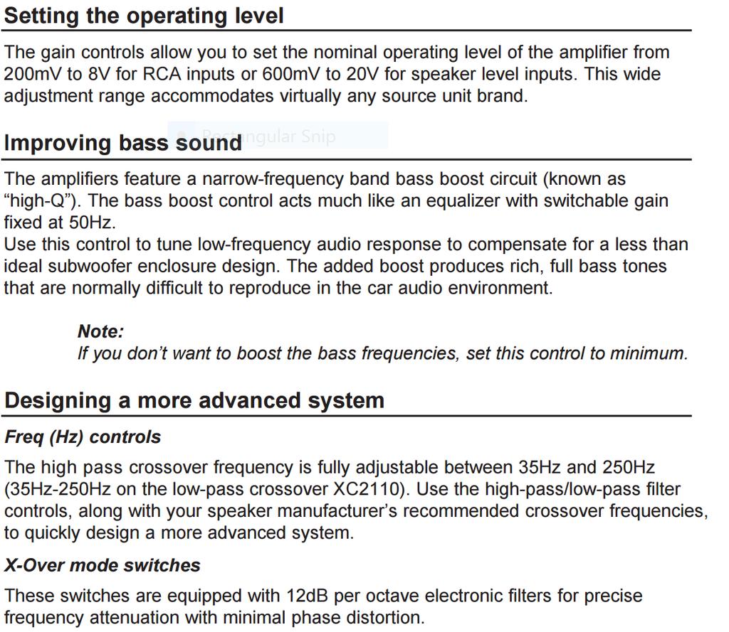
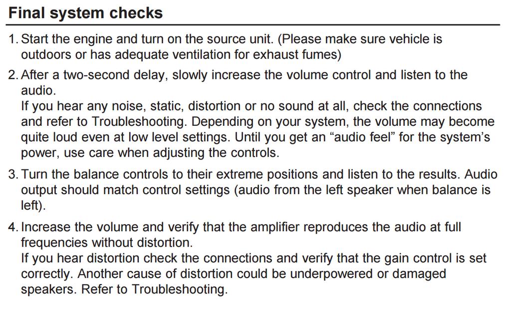
Slowly increase the volume control until you can hear comfortably, clearly and without distortion.
 Dear customer, Congratulations on your purchase of a Bazooka EL high-performance amplifier. At Bazooka, we are fanatics about accurate music reproduction. Your selection of our products for your sound
MITSUBISHI DATA BUS INTERFACE MITO-01 INSTALLATION INSTRUCTIONS
 MITSUBISHI DATA BUS INTERFACE INSTALLATION INSTRUCTIONS * READ IMPORTANT WARNING ON PAGE 2 BEFORE ATTEMPTING ANY INSTALLATION The is designed to be used in vehicles listed in the applications that have
D-Tower Amplifier Series. Owner s Manual
 D-Tower Amplifier Series Owner s Manual CONGRATULATIONS! You now own a D-Tower Amplifier, the product of an uncompromising design and engineering philosophy. We suggest you take a moment to document the
BOB SLAY (assembly instructions)
") BOB SLAY (assembly instructions) Items included: 7 x Acrylic cutouts labeled A-G 1 x Acrylic IO Panel 1 x Acrylic locking plate of PCI cards 2 x Acrylic 5.25 spacers 2 x momentary switches (power/reset)
BOB SLAY (assembly instructions) Items included: 7 x Acrylic cutouts labeled A-G 1 x Acrylic IO Panel 1 x Acrylic locking plate of PCI cards 2 x Acrylic 5.25 spacers 2 x momentary switches (power/reset)
JK Titan Tub Armor 2 and 4 Door
 JK Titan Tub Armor 2 and 4 Door Thank you for purchasing one of our quality products. From product conception to the moment we packaged this product our focus has been on providing you with the very best.
Warnings. Elite Series Waterproof Amplifiers
 Warnings Read these instructions and keep them for future reference. Carefully follow instructions and follow directions carefully. Keep the amplifier dry, as some liquids may contain minerals that corrode
Operation Manual. Congratulations on purchasing your high quality AIMS Power pure sine inverter!
 Operation Manual Congratulations on purchasing your high quality AIMS Power pure sine inverter! It is very important that you read and understand this instruction manual completely prior to use. Contained
CALRAD 25 series - potentiometers
 25 series - potentiometers audio /linear SUB-MINIATURE VOLUME CONTROLS Linear taper, extremely smooth for quiet operation. 1 2" dia. fits into 1 4" hole. Shaft 3 16" dia. Thread length 7 32", shaft length
Operating, Servicing, and Safety Manual Model # & 72 Ultimate Box & Pan Brake
 Operating, Servicing, and Safety Manual Model # 2800 48 & 72 Ultimate Box & Pan Brake CAUTION: Read and Understand These Operating, Servicing, and Safety Instructions, Before Using This Machine. 1-800-467-2464
English APSM Power Indicator LED 4. Protection Circuit Indicator LED. 1. RCA Input Jacks 2. Remote Bass Level Control
 English APSM-1150 2 1 3 4 1. RCA Input Jacks 2. Remote Bass Level Control 3. Power Indicator LED 4. Protection Circuit Indicator LED 1 5 4 3 2 1. Speaker Connection 2. Ground 3. Remote Turn-on Input 4.
High Performance Monoblock Amplifiers
 GTA High Performance Monoblock Amplifiers Specifications Introduction Thank you for choosing Boston Acoustics and congratulations, you ve made the right choice. You re now equipped for the open road. Your
MX-1 / MX-2 MX-3 / MX-4 MX SERIES OEM INTEGRATION ACCESSORIES
 MX-1 / MX-2 MX-3 / MX-4 MX SERIES OEM INTEGRATION ACCESSORIES MX SERIES OEM INTEGRATION ACCESSORIES INDEX PAGE MX OEM Accessory Overview and Setup...1 Installation...2 MX-1 Feature Descriptions...3-4 MX-1
10" E-Series D-Series - Pair. kit includes (14) (4) (4) It is strongly recommended that this product be installed by a professional.
 (4) (4) It is strongly recommended that this product be installed by a professional.") 2014 GMC 1500 grille installation instructions 10" E-Series D-Series - Pair kit includes (14) (14) (4) 5 /16-18x 5 /8 Button Socket 5 /16-18 Low Profile Nylock Nut M6-1.0x30mm Button Head Socket (14) (4)
2014 GMC 1500 grille installation instructions 10" E-Series D-Series - Pair kit includes (14) (14) (4) 5 /16-18x 5 /8 Button Socket 5 /16-18 Low Profile Nylock Nut M6-1.0x30mm Button Head Socket (14) (4)
Directed Electronics, Inc
 models 2400d 2 2002 Directed Electronics, Inc CONGRATULATIONS Congratulations for choosing a Directed Audio power amplifier from Directed Electronics, the industry leader in high quality automotive security
RPS. XR Front Drive Updates CORPORATION
 FACTORY CAT 1. To start a replacement of the XR Front Wheel Drive, make sure the machine is on level ground with the rear wheels chocked and always disconnect the batteries. 2. Locate the Positive and
MantelMount. TM1A Installation Instructions IMPORTANT SAFETY INSTRUCTIONS - SAVE THESE INSTRUCTIONS
 MantelMount TMA Installation Instructions IMPORTANT SAFETY INSTRUCTIONS - SAVE THESE INSTRUCTIONS TM Thank you for choosing the MantelMount television wall mount. Please read this entire manual before
What is a fastener? A device to locate or hold parts
 What is a fastener? A device to locate or hold parts As a repair technician you will become skilled at removing, reconditioning, replacing, and installing fasteners. An important skill to learn is how
Pocket Printer USER GUIDE
 Pocket Printer USER GUIDE Thank you for purchasing the Polaroid Mint Pocket Printer. This User Guide is intended to provide you with guidelines to ensure that operation of this product is safe and does
CONGRATULATIONS TABLE OF CONTENTS
 models 750d 1500d CONGRATULATIONS Congratulations for choosing a Directed Audio power amplifier from Directed Electronics, the industry leader in high quality automotive security and audio equipment since
English KS-DR3005D POWER AMPLIFIER: INSTRUCTION MANUAL
 KS-DR005D POWER AMPLIFIER: INSTRUCTION MANUAL B5E-009-00/00 [W] WARNING If the fuse blows, first make sure the wires aren t touching to cause a short circuit then replace the old fuse with one with the
A400HLX A600HLX. Installation Assistance. Amplifier Installation and Operation
 3 5 60 125 60 125 2 4 0dB 0dB 12dB 12dB 3 5 60 125 60 125 2 4 8V 8V.3V.3V MODE Amplifier Installation and Operation A400HLX A600HLX 400 MOSFET Power Supply 4 channel bridgeable BASS L-CHX R-CHX LEVEL POWER
Serene arm installation instructions for Easyrig 2.5/3 V0.8 Standard arm documentation
 Serene arm installation instructions for Easyrig 2.5/3 V0.8 Standard arm documentation Congratulations you just got your Serene spring arm! Since we are dealing with very strong torque and forces for the
FILE // 4 GAUGE TERMINAL CONNECTORS DOCUMENT
 04 July, 2018 FILE // 4 GAUGE TERMINAL CONNECTORS DOCUMENT Document Filetype: PDF 293 KB 0 FILE // 4 GAUGE TERMINAL CONNECTORS DOCUMENT Alibaba.com offers 124 4 gauge wire connectors products. Unique Bargains
XPR522 XPR540. XPR SERIES INSTALLATION / OWNER'S MANUAL Mobile Power Amplifiers
 XPR522 XPR540 XPR SERIES INSTALLATION / OWNER'S MANUAL Mobile Power Amplifiers Preparation Please read entire manual before installation. Due to the technical nature of amplifiers, it is highly recommended
TOYOTA TACOMA TRAILER WIRE HARNESS Preparation
 Preparation Part Number: PT725-35120 Kit Contents Item Quantity Reqd. Description # 1 1 Flasher Assembly (F/A) 2 1 Wire Harness 3 1 Sub Wire Harness 4 2 Plastic Tie (300mm) 5 4 Plastic Tie (200mm) 6 13
UNDERGROUND INSTRUCTION & INSTALLATION MANUAL. active. enclosure MODEL: FU10A, FU12A, FU12TA
 UNDERGROUND INSTRUCTION & INSTALLATION MANUAL active enclosure MODEL: FU10A, FU12A, FU12TA 2 Thank you for purchasing this FLI UNDERGROUND subwoofer enclosure. It will provide you with years of trouble
HIGH PERFORMANCE MARINE AUDIO HTX SERIES HTX-1, HTX-2, HTX-4, HTX-6 OWNER'S MANUAL. wetsounds.com
 HIGH PERFORMANCE MARINE AUDIO HTX SERIES HTX-1, HTX-2, HTX-4, HTX-6 OWNER'S MANUAL wetsounds.com CONGRATULATIONS! Thank you for purchasing the Wet Sounds Hydro-Tech TM X (HTX) series amplifier. Wet Sounds
Hatchback Wing Riser Kit
 Hatchback Wing Riser Kit 2015-06-11 Thank you for purchasing this PERRIN product for your car! Installation of this product should only be performed by persons experienced with installation of aftermarket
MODEL: M1u Product id:m1ud13 M1u OWNER S MANUAL
 MODEL: Product id:m1ud13 OWNER S MANUAL Foreword We congratulate you with your decision to purchase our reveered niche amplifiers. Every product developed by implements the keystones of our company philosophy;
 Menu Board Tilt or Fixed Mount Installation Instructions MDS1T-200, MDS1T-300, MDS1T-400 MDS2T-200, MDS2T-300, MDS2T-400 MDS3T-200, MDS3T-300, MDS3T-400 MDS4T-200, MDS4T-300, MDS4T-400 MDS5T-200, MDS5T-300,
Obtained from Omarshauntedtrail.com
 http://www.scary-terry.com/dancskele/dancskele.htm This is a how-to for making a set of dancing skeletons for your Halloween window display. It uses a pair of cheap, glow-in-the-dark plastic skeletons
SAFETY THIS PRODUCT IS FOR OFFROAD USE ONLY. ALL LIABILITY FOR INSTALLATION AND USE RESTS WITH THE OWNER.
 SAFETY Your safety and the safety of others is very important. In order to help you make informed decisions about safety, we have provided installation instructions and other information. These instructions
Assembly instructions
 Assembly instructions Important notes on VOSS assembly instructions In order to ensure maximum performance and functional reliability of VOSS products, the respective assembly instructions, operating conditions
ACCESS COVER INSTALLATION INSTRUCTIONS (Kit #601 for 2006 Honda Ridgeline)
") ACCESS COVER INSTALLATION INSTRUCTIONS (Kit #601 for 2006 Honda Ridgeline) NOTE TO INSTALLER: IMPORTANT READ BEFORE ATTEMPTING INSTALLATION. Allow extra time, up to 2 hours to install this cover. Disassembly
ACCESS COVER INSTALLATION INSTRUCTIONS (Kit #601 for 2006 Honda Ridgeline) NOTE TO INSTALLER: IMPORTANT READ BEFORE ATTEMPTING INSTALLATION. Allow extra time, up to 2 hours to install this cover. Disassembly
SYN-DX SERIES FULL RANGE CLASS-D AMPLIFIERS SYN-DX 2, SYN-DX 2.3 HP, SYN-DX 4, SYN-DX 6 OWNER'S MANUAL. wetsounds.com HIGH PERFORMANCE MARINE AUDIO
 HIGH PERFORMANCE MARINE AUDIO SYN-DX SERIES FULL RANGE CLASS-D AMPLIFIERS SYN-DX 2, SYN-DX 2.3 HP, SYN-DX 4, SYN-DX 6 OWNER'S MANUAL REV DATE FEB 2017 wetsounds.com CONGRATULATIONS! Thank you for purchasing
XDi Full Range Class D Amplifier OWNER S MANUAL
 www.arcaudio.com OWNER S MANUAL XDi 1100.5 Full Range Class D Amplifier Introduction 1 Finding a Suitable Location 1 Supplying Power 1 The Ground 1 Running the Cables 2 Class D amplifiers 2 Diagnostic
HONDA RIDGELINE (KIT #601) Installation Instructions (to be used in addition to owners manual)
 Installation Instructions (to be used in addition to owners manual)") HONDA RIDGELINE (KIT #601) Installation Instructions (to be used in addition to owners manual) IMPORTANT NOTE: Read before beginning installation. These instructions replace all of Step 1 of the instructions
HONDA RIDGELINE (KIT #601) Installation Instructions (to be used in addition to owners manual) IMPORTANT NOTE: Read before beginning installation. These instructions replace all of Step 1 of the instructions
NEMESIS NC-200A OPERATION MANUAL
 NEMESIS NC-200A OPERATION MANUAL Publishing Date 6/10/96 Rev.4 Congratulations on your purchase of your new NEMESIS Combo Amplifier system. This manual will cover all (4) versions of the NEMESIS Combos.
JHD910BT. Owner s Manual JENSEN HEAVY DUTY MUTE DISP AM/FM AUX WB TIMER JENSEN AM/FM/WB JHD910BT VOL+ AUDIO MENU VOL- SEEK SEEK
 Owner s Manual JENSEN MUTE DISP AM/FM AUX WB TIMER JENSEN HEAVY DUTY VOL+ TUN AUDIO MENU TUN + VOL- SEEK AM/FM/WB JHD910BT 1 2 3 4 5 6 SEEK + AUXIN CONTENTS Installation... 3 Wiring... 4 Basic Operation...
WEAR SAFETY GLASSES WHEN INSTALLING THIS KIT.
 INSTALLATION INSTRUCTIONS Trans4mer Mounting Systems Part No. 29753 (black) Part No. 65654 (stainless) for full size GM pickups, and Blazer, Yukon, Suburban, Tahoe As you read these instructions, you will
SECTION 7. SAFETYING
 9/8/98 AC 43.13-1B SECTION 7. SAFETYING 7-122. GENERAL. The word safetying is a term universally used in the aircraft industry. Briefly, safetying is defined as: Securing by various means any nut, bolt,
TOYOTA TACOMA 2005 TRAILER WIRE HARNESS Preparation
 Preparation Part Number: 08921 04960 NOTE: Part number of this accessory may not be the same as the part number shown. Kit Contents Item # Quantity Reqd. Description 1 1 Converter Assembl y 2 1 Wire Harness
FORD MOUNT INSTALLATION INSTRUCTIONS
 WESTERN PRODUCTS, P.O. BOX 245038, MILWAUKEE, WI 53224-9538 Lit. No. 64289 June 1, 2003 FORD MOUNT INSTALLATION INSTRUCTIONS Bronco (4X4 only) F-150 (4X4 only), F-250/350 Super Duty 1980 1991 Model No.