2015 ed. FX Type: Univibe 2015 madbeanpedals W x 3.29 H
|
|
|
- Sharlene Palmer
- 5 years ago
- Views:
Transcription


1 Harbinger One 2015 ed. FX Type: Univibe 2015 madbeanpedals 3.25 W x 3.29 H Harbinger One PCBs purchased form madbeanpedals may be used for small amounts of commercial building without prior consent. Keep in mind that quantity discounts are not offered on PCBs. The use of the PCBs for resale or as part of a kit is strictly forbidden.
2 2
3 B.O.M. Resistors Resistors Caps Diodes R1 22K R32 4k7 C1 1uF D1 - D3 1N5817 R2 47k R33 4k7 C2 1uF D4, D5 1n914 R3 1M R34 100k C3 330pF D6 15v Zener R4 5k6 R35 47k C4 1uF Transistors R5 1M R36 22k C5 1uF Q1 2N5089 R6 100k R37 68k C6 1uF Q2 - Q13 2N5088 R7 47k R38 3k3 C7 15n Q14 J201 R8 4k7 R39 2M2 C8 1uF Q15 2N5087 R9 3k3 R40 4k7 C9 1uF I.C. R10 1k2 R41 4k7 C10 220n IC1 LT1054 R11 100k R42 220k C11 1uF IC2 LM7815 R12 100k R43 4k7 C12 1uF Switches R13 47k R44 220k C13 1uF MD/VN DPDT R14 220k R45 4k7 C14 470pF C/V SPDT R15 4k7 R46 4k7 C15 1uF Lamp R16 100k R47 22R C16 1uF L1 LM7371 R17 47k R48 12k C17 4n7 Trimmer R18 4k7 R49 1K C18 1uF GAIN 500R R19 100k R50 1M C22 1uF OFFSET 250k R20 4k7 R51 4k7 C23 1uF Pots R21 4k7 R52 47k C24 1uF SPD1, 2 100kC Dual R22 100k R53 47k C25 1uF INT 50kB R23 47k R54 1k C26 10uF VOL 100kB R24 4k7 R55 1M C27 10uF R25 100k R56 10k C28 100n R26 4k7 C29 100n R27 4k7 C30 100uF R28 100k C31 47uF R29 47k C32 470uF R30 4k7 C33 100n R31 100k C34 100uF 3
4 Shopping List Value QTY Type Rating 22R 1 Metal / Carbon Film 1/4W 1K 2 Metal / Carbon Film 1/4W 1k2 1 Metal / Carbon Film 1/4W 3k3 2 Metal / Carbon Film 1/4W 4k7 17 Metal / Carbon Film 1/4W 5k6 1 Metal / Carbon Film 1/4W 10k 1 Metal / Carbon Film 1/4W 12k 1 Metal / Carbon Film 1/4W 22K 2 Metal / Carbon Film 1/4W 47k 9 Metal / Carbon Film 1/4W 68k 1 Metal / Carbon Film 1/4W 100k 10 Metal / Carbon Film 1/4W 220k 3 Metal / Carbon Film 1/4W 1M 4 Metal / Carbon Film 1/4W 2M2 1 Metal / Carbon Film 1/4W 330pF 1 Ceramic 25v min 470pF 1 Ceramic 25v min 4n7 1 Film 25v min 15n 1 Film 25v min 100n 3 Film 25v min 220n 1 Film 25v min 1uF 13 Film 25v min 1uF 4 Electrolytic 25v min 10uF 2 Electrolytic 25v 47uF 1 Electrolytic 25v 100uF 2 Electrolytic 25v 470uF 1 Electrolytic 25v 1N n v Zener 1 1W 2N N J N LT LM TO-220 DPDT 1 On/On SPDT 1 On/On LM R 1 Bourns 3362P 250k 1 Bourns 3362P 100kC Dual 1 Solder Lug Dual 50kB 1 PCB Short Pin 100kB 1 PCB Short Pin DPDT On/On: SPDT On/On: Lamp: Alternate (smaller): 100kC Pot: 4
5 1590BB Drilling Guide 5.8 W x 6.8 H Note: A 125BB will more easily accommodate a larger light shield. You can use this drill guide for the 125BB and simply re-position the jackson the side-wall. You can also use a 1590BB Tall. The difference is the 125BB is the 1590BB with the height of the 125B. The 1590BB Tall is a 1590BB with 2" tall walls (much taller than the 125BB). 5


6 Wiring 6
7 2015 Change Log Re-worked power supply to eliminate daughter board. Re-positioned I/O pads. Added new LED flasher circuit. Converted switches to PCB pin mount Update: Switches can be either PCB mount or solder lug Update Change R55 from 22k to 1M to prevent the Rate LED from stopping at slowest speeds (Thanks Jon!) Overview The Harbinger One is a classic Univibe circuit updated to meet the needs of the modern guitar player. It retains all the essence of the vintage Univibe unit (made popular by Jimi Hendrix and Robin Trower) with added improvements to both the signal path and power supply chains. The Harbinger One will add a dimension to your sound that cannot be obtained through any other type of effect. Richer and lusher than the standard phaser or vibrato, the Harbinger imparts a classic tone that is instantly recognizable. This is a difficult and complex build and should not be undertaken by the novice. You should feel comfortable with stuffing and soldering a large number of components, the use of standard debugging techniques and the use of a DMM to measure voltages. Further reading on the inner workings of the Univibe: Controls SPD The rate of the filter sweep from slow to fast. INT The intensity of the swept filter. VOL The output volume. C/V This switch selects a chorus effect (filter mixed with dry signal) or vibrato effect (filter output only). VN/MD This switch selects between the traditional input and a JFET buffer input. GAIN This trimmer sets the brightness of the LFO-driven bi-pin lamp. OFFSET This trimmer lets you adjust the ramping of the lamp s brightness. Mods Power options: The Harbinger One can be built to run off either an 18v DC adaptor or a 9v DC adaptor in conjunction with a charge pump to attain the 18v required to operate the effect. Signal path: All the 1uF electrolytic caps in the stock design have been replaced with 1uF film caps. Lamp: The OFFSET trimmer greatly increases tweaking ability on the on/off ramping of the lamp brightness. 7
8 Modern mode: The switch-able JFET input buffer adds brightness, more volume and increased intensity to the overall effect. Layout: The PCB will fit easily in a 1590BB enclosure in a horizontal orientation to save space on your pedalboard. However, you may prefer to use a 125BB for added height. This is the same width and height as the 1590BB but with the added height of a 125B. The extra height will allow a light shield to fit more easily. If using a 125BB utilize the drill guide on page 5 and simply move the drill locations for the jacks to approximately the middle of the enclosure wall. Power supply: The audio signal path was made to run off 18vDC unregulated for the maximum headroom possible. The LFO section is run off 15v regulated for the maximum stability possible. Power Options You can build the Harbinger One for use with either a 9v or 18v DC adaptor. There are advantages and disadvantages to both: 18v wall-wart adaptor Advantage - Offers a larger current supply than can be provided by a charge pump. Disadvantage - Requires the use of a wall-wart which may be inconvenient. 9v wall-wart adaptor OR dedicated power supply Advantage - More typical of the type of power supply we all use (such as the VoodooLabs PP2). Disadvantage - Requires the use of a charge pump to drive the effect and is limited to 100mA output. In the case of the 9v power supply option, I ve found that 100mA is sufficient to operate the Harbinger. Keep in mind this is not the adaptor limit---it s the limit of the LT1054 charge pump. You should be able to use the VoodooLabs power supply or a One Spot to power the Harbinger without problems. If you decide to go with the 18v adaptor option, I suggest using the Dunlop one. It has 200mA capability and worked fine in the prototype builds. Note: some of the newer multi-power supplies out there offer isolated/regulated 18v taps. If you have this, then you can use that instead of an 18v wall-wart. You can obtain the virtually identical tones between the different power options, as far as I can tell. I did find that the maximum brightness of the lamp was a bit lower when using the 9v/charge pump option. For this reason I suggest socketing Q13 and subbing a Darlington transistor there if you have trouble getting the intensity you want from the lamp. An MPSA13 will work fine (this is not listed on the BOM). I did not find this to be necessary, but it is an option. 8
9 Building the power The power section for the 2015 edition has been simplified. Here are the steps to use the two power options. 18v Dunlop Wall Wart Populate D1, C32, C33, IC2 and C34. Do not populate C30, D6, IC1, D2, D3 or C31. 9v Power Populate everything except D1. In either case, R48 and LED2 are populated (this is your indicator LED) Note about the indicator LED: This LED is powered by the 18v output. This is not ideal when using a charge pump due to the extra current draw it requires (it was necessary to do to fit on the PCB layout). If you are using a charge pump, you can omit R48 and wire your LED/resistor combo directly to the DC jack to power it from the 9v tap instead. It may not be necessary, but there is no downside to it either. FWIW. Light Shield The Harbinger One provides space for a lightshield. This is a cover that traps the light emitted from the bulb to provide the cleanest source of illumination possible to the four photocells. This is an essential part of building a Univibe effect as the quality of light, lamp and photocells has a direct impact on the overall tone. There are four solder pads (denoted by the circles) arranged in a square which comprise the limits of the lightshield dimensions. These are space 0.75 apart. 9


10 You can construct the lightshield any way you like. Here s a cheap way to do it: This is a tiny drain cap from a hardware store. The cap is a perfect size, but has drain holes that would let light leak out. I used some reflective roof tape on the inside of the cap and electrical tape on the outside and bottom edges. This completed shield fits snugly into place over the lamp and photocells and can be further secured by wires soldered to the four solder pads shown above. The roofing tape was useful because it reflected all the light coming from the top and sides of the lamp around inside, thus ensuring that each photocell got the same amount of illumination. Not all light shields are made to be reflective inside. I ve seen at least one popular Univibe clone that had a shield that was flat black. Different builders solder the photocells in different ways, too. Some like to put them in flat against the PCB, and some like to use the leads from the photocells as standoffs, then angle the photocells directly at the lamp (thus requiring less need for reflected light). There is no one correct way to do it all these methods will work. But, if you want to build a true to vintage specs Univibe, put the photocells in flat against the PCB and use a reflective lightshield. 10

11 Of course, each method will get a mix of direct and reflected light. And, I m sure there is someone out there willing to take on the task of explaining the possible advantages of incidence angles, reflective indexes, diffusion patterns and their history in the construction of Univibes and their many clones. Fortunately for me, I am not that person. Photocells and Lamps I ve suggested Silonex 7532 photocells because I ve used them with good results and they are popular for Univibe clones. But, they are by no means the ONLY ones you can use. Garden variety Tayda photocells may work. If you are using random/unknown photocells, I suggest trying to match their light resistance. You can do this by mounting photocells on a breadboard with a light shining directly at their face, then measuring the resistance across the leads. Pick the four cells that match closest in resistance. If you want to go an extra step, cover the faces with some Blutac and match their dark resistance, too. I used this matching method with an optical phaser build and it worked great. The 7371 lamp is also suggested because, again, I ve used it with good result and it is very common. If you are ordering from Smallbear and don t mind spending an extra $1, get one of these, too, for experimenting: (Mouser also has them). This is the lamp used in the MBP Quadrovibe project. It also works in Univibe setups AND has the advantage of being smaller than the 7371 (which means your lightshield does not have to be very tall ((which means it will fit very easily in the regular 1590BB enclosure))). Calibrating the Lamp The GAIN and OFFSET controls are interactive. Use this procedure to calibrate the lamp 1) Turn Intensity and Volume controls all the way up. Set the Speed control at about halfway. 2) Turn the GAIN control up until you get moderate, but not overly bright lighting of the lamp. 3) Now adjust the OFFSET control to find the sweet spot for the vibe where you get the most lush and swirly sounds. The OFFSET will set the lower floor for the lamp brightness. High amounts of offset result in a lamp that goes fully off at the bottom of its sweep. Moderate and light offset means the lamp 11

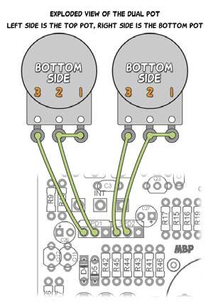
12 will pulse but never go fully dark. You will probably find yourself adjusting the GAIN and OFSET a few times until you get the precise sound you want. Be careful when adjusting the trimmers so that the lamp does not blow. I have yet to do this in any build no matter where I set the trimmers, but it is possible to do. Lastly, you should consider turning off your power supply or disconnecting the DC jack when not in use. This will preserve the life of the lamp considerably. Rate LED The LED pads directly above the OFFSET trimmer are for an optional enclosure-mounted rate indicator. This LED will pulse approximately to the rate of the Speed control. Low speeds will pulse very narrow and fast speeds will pulse very widely. If you do not wish to use this LED, be sure to jumper the two pads together so that R45 is connected to ground, otherwise the LFO will not work. The LED will pulse constantly even when the effect is in bypass. Note: Change R55 to 1M for better operation. Speed Pot The SPD pot on the Harbinger must be wired, unlike the INT and VOL pots, which can be PCB mounted. The best way to do this is run the wires under the PCB. This keeps the top free for trimmer adjustment (plus it looks cleaner this way). The dual-gang 100kC (the C stands for reverse audio) has two rows of solder lugs. The bottom lugs are bent at a 90 degree angle. This may cause a problem when placing the pot under the PCB the lugs could come into contact with solder joints on the board. You should GENTLY bend these pins flat with a pair of pliers before soldering the wires. This will ensure adequate space between the pot and PCB. BTW: It does not matter which row of lugs is wired to SPD1 or SPD2 on the PCB (just that both sets are actually wired). (This photo courtesy of Smallbear) 12
13 Voltages v supply Q1 2N5089 Q2 2N5088 Q3 2N5088 Q4 2N5088 C 2.14 C 4.4 C 13.8 C 17.8 B 1.45 B 2.14 B 4.4 B 5.6 E 1.03 E 1.57 E 3.8 E 5.3 Q5 2N5088 Q6 2N5088 Q7 2N5088 Q8 2N5088 C 13.2 C 17.8 C 13.2 C 17.8 B 5.4 B 5.6 B 5.7 B 5.6 E 4.7 E 5.3 E 4.7 E 5.2 Q9 2N5088 Q10 2N5088 Q11 2N5088 Q12 2N5088 C 13.2 C 17.8 C 15.1 C 15.1 B 5.2 B 7.1 B varies B varies E 4.6 E 6.7 E varies E varies Q13 2N5088 Q14 J201 IC1 LT1054 REG LM7815 C varies D I 17.8 B varies S G 0 E vaires G 4mV 3 2mV O mV 5 175mV These readings were taken off the prototype PCB which did not include the Rate LED circuitry. You should read 15v on the Q15 Collector, with some varying voltage on the Base and Emitter. 13
Stage Fright 2015 edition FX TYPE: Phaser Based on the Maestro Phaser 2015 madbeanpedals
 Stage Fright 2015 edition FX TYPE: Phaser Based on the Maestro Phaser 2015 madbeanpedals 2.3" W x 3.45" H Previous Version: http://www.madbeanpedals.com/stagefright/stagefright.zip Terms of Use: You are
2.15 W x 1.95 H. Changes to the 2015 edition
 NOM NOM FX Type: Filter 2015 edition Based on the MXR Phase 90 2015 madbeanpedals Download the previous version documentation here: http://www.madbeanpedals.com/projects/nomnom/nomnom.zip 2.15 W x 1.95
presents FX TYPE: VIBRATO m2011 madbeanpedals Release date: revised see highlighted notes Thanks, Paul!
 http://www.madbeanpedals.com presents Quadrovibe FX TYPE: VIBRATO m2011 madbeanpedals Release date: 07.1.11 revised 10.26 see highlighted notes Thanks, Paul! The Quadrovibe is a unique Vibrato/Tremolo
Dirtbaby FX TYPE: Delay Based on the EHX DMM 2016 madbeanpedals
 Dirtbaby FX TYPE: Delay Based on the EHX DMM 2016 madbeanpedals 3.325 W x 2.325 H Terms of Use: You are free to use purchased circuit boards for both DIY and small commercial operations. You may not offer
Total Recall FX Type: Delay Based on the EHX Deluxe Memory Man 2015 madbeanpedals
 Total Recall FX Type: Delay Based on the EHX Deluxe Memory Man 2015 madbeanpedals 3.34" W x 3.875" H Terms of Use: You are free to use purchased Total Recall circuit boards for both DIY and small commercial
Tractor BEam. FX TYPE: Phaser Images VFE and MBP Project Doc madbeanpedals
 Tractor BEam FX TYPE: Phaser Images VFE and MBP Project Doc madbeanpedals 2.17 W x 2.02 H Note: This project is built on the Enterprise PCB. It s the same circuit as the Tractor Beam with a few value modifications.
FREEKOUT FX TYPE: Ring Modulator Based on the EHX Frequency Analyzer 2015 madbeanpedals
 FREEKOUT FX TYPE: Ring Modulator Based on the EHX Frequency Analyzer 2015 madbeanpedals 2.3 W x 3.025 H This project requires an 18v 100mA (or more) center tip negative power supply. I recommend the Dunlop
Cave Dweller 2015 edition FX Type: Delay 2015 madbeanpedals
 Cave Dweller 2015 edition FX Type: Delay 2015 madbeanpedals 1.3" W x 1.975" H (main board) Previous Version: http://www.madbeanpedals.com/projects/cavedweller/cavedweller_drill.zip Terms of Use: You are
Weener Wah FX TYPE: Wah Wah Based on the Clyde McCoy 2016 edition madbeanpedals
 Weener Wah FX TYPE: Wah Wah Based on the Clyde McCoy 2016 edition madbeanpedals 1.95 W x 2.275 H Terms of Use: You are free to use purchased WeenerWah circuit boards for both DIY and small commercial operations.
VFE Choral Reef. FX TYPE: Chorus Images VFE and MBP Project Doc madbeanpedals Aug. 2 nd update see pg W x 2.05 H
 VFE Choral Reef FX TYPE: Chorus Images VFE and MBP Project Doc madbeanpedals Aug. 2 nd update see pg.4 2.17 W x 2.05 H Terms of Use: These projects are intended for DIY use only and may not be used in
Dig Dug madbeanpedals FX Type: Sequencer W x 3.25 H
 Dig Dug2 2015 madbeanpedals FX Type: Sequencer 4.15 W x 3.25 H B.O.M. Resistors Caps Diodes R1 1M C1 100n D1 1N5817 R2 1M C2 220n D2 - D4 1n914 R3 10k C3 15n LED1-8 3mm Red R4 330k C4 2n2 PATT 3mm Red
VFE Merman. FX TYPE: Overdrive Images VFE and MBP Project Doc madbeanpedals W x H
 VFE Merman FX TYPE: Overdrive Images VFE and MBP Project Doc madbeanpedals 2.17 W x 2.025 H Note: Use the values listed on the image above not the values indicated on the silk-screen of the PCB. Some values
Mobius Strip. FX TYPE: Dual Delay Images VFE and MBP Project Doc madbeanpedals W x H
 Mobius Strip FX TYPE: Dual Delay Images VFE and MBP Project Doc madbeanpedals 2.17 W x 2.025 H Note: Use the values listed on the image above not the values indicated on the silk-screen of the PCB. Some
Blueprint. FX TYPE: Delay Images VFE and MBP Project Doc madbeanpedals W x H
 Blueprint FX TYPE: Delay Images VFE and MBP Project Doc madbeanpedals 2.17 W x 2.025 H Note: Use the values listed on the image above not the values indicated on the silk-screen of the PCB. Some values
Blues King. FX TYPE: Overdrive Images VFE and MBP Project Doc madbeanpedals W x H
 Blues King FX TYPE: Overdrive Images VFE and MBP Project Doc madbeanpedals 2.17 W x 2.025 H Note: Use the values listed on the image above not the values indicated on the silk-screen of the PCB. Some values
Aquaboy FX TYPE: Delay Based on the Boss DM madbeanpedals
 Aquaboy FX TYPE: Delay Based on the Boss DM-2 2016 madbeanpedals 2.3 W x 3.125 H 1.29.17 Correction see page 6. Note: the M pad by the Delay pot is for modulation control (see the AB_MOD documentation
Triumvirate. FX TYPE: Multi-Band Distortion Images VFE and MBP Project Doc madbeanpedals W x 2.01 H
 Triumvirate FX TYPE: Multi-Band Distortion Images VFE and MBP Project Doc madbeanpedals 2.17 W x 2.01 H Note: Use the values listed on the image above not the values indicated on the silk-screen of the
PCB by 1776 Effects/JRM 2013 Circuit Design by Jon Patton
 Cardinal Tremolo PCB by 1776 Effects/JRM 2013 Circuit Design by Jon Patton The Cardinal Tremolo is a transistor and vactrol implementation of the Harmonic Tremolo. It resembles the harmonic tremolo from
FX Type: Distortion 1.95 W x H Terms of Use: Slow Loris Slow Loris
 Slow Loris 2015 edition madbeanpedals FX Type: Distortion Based on the ProCo Rat Changes for the 2015 edition: Slight layout adjustments. No circuit changes. Previous version: http://www.madbeanpedals.com/projects/slowloris/docs/slowloris.zip
Guitarpedalkits.com Overdrive Pedal Build Instructions
 Page 1 Guitarpedalkits.com Overdrive Pedal Build Instructions Follow the instructions in this guide to build your very own DIY overdrive pedal from GuitarPedalKits.com. If you re a first time builder,
LunarBlast v1.0. Optical Tremolo. Description:
 LunarBlast v1.0 Optical Tremolo Description: Based on the venerable DIY Tremulus Lune classic circuit, www.madbean.com forum member CultureJam created this awesome sounding tremolo dubbed the Shoot the
The Triplet. FX TYPE: Comp+Oct+Dist Images VFE and MBP Project Doc madbeanpedals W x H
 The Triplet FX TYPE: Comp+Oct+Dist Images VFE and MBP Project Doc madbeanpedals 2.17 W x 2.025 H Note: Use the values listed on the image above not the values indicated on the silk-screen of the PCB. Some
Build Guide CascadiA. GeFet Preamp
 Build Guide CascadiA GeFet Preamp Disclaimery stuff: This project is meant to be assembled by fellow DIYers from the Madbean forum and should only be used for the forces of good. Any other uses prohibited
NEW WAVE CV GENERATOR Build Document last updated september 2017 for PCB version 1.0
 NEW WAVE CV GENERATOR Build Document last updated september 2017 for PCB version 1.0 The New Wave is a Control Voltage Generator. It has two LFO's (low frequency oscillators) and four different output
Electric Druid Flangelicious Flanger Project
 Electric Druid Flangelicious Flanger Project (Using either 4KNOBFLANGE or MULTIFLANGE chips) Overview! 2 Build Instructions! 2 Populate the PCB! 2 1N4148 Diodes! 2 Resistors! 2 Cup of tea and soldering
UVICS. The circuit of the. Includes. Son of UVICS
 UVICS The circuit of the UniVibe In a Crybaby Shell Includes Son of UVICS Updated 6-3-2013 Table of Contents UVICS Toner Pattern... UVICS Population diagram... Yada Yada Son of UVICS... Son of UVICS Toner
Electric Druid 4 second Digital Delay Project
 Electric Druid 4 second Digital Delay Project Overview! 2 Build Instructions! 2 Populate the PCB! 2 Resistors! 2 Cup of tea and soldering check! 3 Power protection diode! 4 Ground link wire! 4 IC sockets!
VFE Switching Board madbeanpedals Some images 2017 VFE Pedals, used with permission 8.7 update: see pg W x 1.33 H
 VFE Switching Board 2017 madbeanpedals Some images 2017 VFE Pedals, used with permission 8.7 update: see pg. 7 2.16 W x 1.33 H The VFE Switching Board and micro-controller are included with all the VFE
Super Nova Distortion
 Super Nova Distortion The Super Nova is a reworking of the Marshall Guv'nor circuit. It uses the same gain structure as its parent design but is EQ'ed quite differently. The basic tone from the gain stages
TS500 Assembly guide. Soldering. TS500 Assembly guide Main PCB 1. Diodes. Document revision 1.2 Last modification : 17/12/16
 TS500 Assembly guide Safety warning The kits are main powered and use potentially lethal voltages. Under no circumstance should someone undertake the realisation of a kit unless he has full knowledge about
INTO THE UNKNOWN Build Document last updated may 2016 Version
 INTO THE UNKNOWN Build Document last updated may 2016 Version 1.0 2015 'Into the Unknown Guitar Synthesizer Deluxe' is a CMOS based fuzz centered around the CD4046 PLL (phase locked loop) chip and a CD4015
BYOC Vibrato Kit Instructions BA6110 version
 BYOC Vibrato Kit Instructions BA6110 version Please read these instructions very thoroughly before building even if you are an experience builder. Because of the
BYOC Vibrato Kit Instructions BA662A version
 BYOC Vibrato Kit Instructions BA662A version Please read these instructions very thoroughly before building even if you are an experience builder. Because of the layout, there is a certain order which
Build Your Own Clone Classic Overdrive Kit Instructions
 Build Your Own Clone Classic Overdrive Kit Instructions Warranty: BYOC, LLC guarantees that your kit will be complete and that all parts and components will arrive as described, functioning and free of
Axis Fuzz Kit Building Manual
 Axis Fuzz Kit Building Manual Effect Pedal Kits: Axis Fuzz The Axis Fuzz Kit is based in the Roger Mayer Axis Fuzz, the effect pedal responsible for Jimi Hendrix sound in Axis Bold As Love. What else is
Rangemaster Treble Booster Kit Building Manual
 Rangemaster Treble Booster Kit Building Manual Effect Pedal Kits: Rangemaster Treble Booster The Dallas Rangemaster is the most famous treble booster effect pedal, and it was the first pedal of its kind.
Multiwave. Guitar Synthesizer. Build Document last updated november 2018 Version
 Multiwave Guitar Synthesizer Build Document last updated november 2018 Version 1.0 2018 The Multiwave is a guitar controlled oscillator with 3 different waveshapes: saw, triangle and square. Combined,
LA502 Assembly guide Main PCB Resistors - (2)
") LA502 Assembly guide Safety warning The kits are main powered and use potentially lethal voltages. Under no circumstance should someone undertake the realisation of a kit unless he has full knowledge about
LA502 Assembly guide Safety warning The kits are main powered and use potentially lethal voltages. Under no circumstance should someone undertake the realisation of a kit unless he has full knowledge about
Standard JFET input buffer and Standard NPN Output buffer
 Board Standard JFET input buffer and Standard NPN Output buffer By PCB Guitar mania Mania Project link The buffers are normally added into a circuit to prevent loading and loss of definition of the guitar
BMC017. 2LFOSH Last updated I Features II Schematics III Construction
 BMC017. 2LFOSH Last updated 12-3-2013 I Features II Schematics III Construction I. Features The 2LFOSH module is a combination of three different modules on one board, designed to be easy to be easy to
Build Your Own Clone Mouse Kit Instructions
 Build Your Own Clone Mouse Kit Instructions Warranty: BYOC, Inc. guarantees that your kit will be complete and that all parts and components will arrive as described, functioning and free of defect. Soldering,
N3ZI Kits General Coverage Receiver, Assembly & Operations Manual (For Jun 2011 PCB ) Version 3.33, Jan 2012
 Version 3.33, Jan 2012") N3ZI Kits General Coverage Receiver, Assembly & Operations Manual (For Jun 2011 PCB ) Version 3.33, Jan 2012 Thank you for purchasing my general coverage receiver kit. You can use the photo above as a
N3ZI Kits General Coverage Receiver, Assembly & Operations Manual (For Jun 2011 PCB ) Version 3.33, Jan 2012 Thank you for purchasing my general coverage receiver kit. You can use the photo above as a
Switcher Assembly guide. Switcher Assembly guide 1. Soldering. 2. Switcher3 vs Switcher2. 3. PCB split.
 Safety warning The kits are main powered and use potentially lethal voltages. Under no circumstance should someone undertake the realisation of a kit unless he has full knowledge about safely handling
Liquid Mercury Phaser. Build doc V2.0
 Liquid Mercury Phaser Build doc V2.0 David Rolo / December 2014 The build consists of 2 boards that were designed to fit in a BB enclosure with top mounted open jacks. PCB1 holds the pcb mounted pots and
Value Location Qty Transistors 2N5485 Q1, Q2, 4 Q3, Q4 2N5087 Q5 1. Trim Pots 250k VTRIM 1. Potentiometers C500k Speed 1. Toggle Switch On/On Vibe 1
 P-90 BUILD INSTRUCTIONS Thank you for your purchase of our P-90 kit! We have completely redesigned our entire line of kits to be the most user friendly, while still maintaining their same great sound!
Mono Amplifier. LM386 Headphone Amp
 Mono Amplifier LM386 Headphone Amp Layout On/Off Switch - cuts power to the circuit Mono Input Jack: use either L or R or solder together Schematic Step 1 - Parts List 1.) R1-10ohm Resistor - Brown Black
BassAce - Midi Bass Synthesizer. BassAce Features
 Untitled Document BassAce - Midi Bass Synthesizer The BassAce is a small midi-synth based loosely on the TB303. It can be built many different ways. Depending on how it's configured it can be anything
GuitarPCB.com Angry Red Camel Build Instructions
 GuitarPCB.com Angry Red Camel Build Instructions Board Dimensions (W x H) 1.95 x 1.65 inches, i.e.: 49.5 x 41.9mm. This design will fit into a 1290NS/1590B size enclosure or larger. This is a variant of
Simple LFO Features. 2. Application. 3. Description. Simple and easy to build LFO module for Analog Synthesizers.
 Simple LFO. Simple and easy to build LFO module for Analog Synthesizers.. Features Square and Triangle waveforms (90 phase shifted) Dual range frequencies Frequency ranges from under Hz up to several khz
Build Your Own Clone Classic Phaser Kit Instructions
 Build Your Own Clone Classic Phaser Kit Instructions Warranty: BYOC, Inc. guarantees that your kit will be complete and that all parts and components will arrive as described, functioning and free of defect.
THE GREEN CURRANT TREMOLO Build Document last updated june 2017 for PCB version 1.5
 THE GREEN CURRANT TREMOLO Build Document last updated june 2017 for PCB version 1.5 The Green Currant tremolo is a very percussive and vibey tremolo based around the TDA7052A amplifier chip. It splits
Build Your Own Clone Green Pony Kit Instructions
 Build Your Own Clone Green Pony Kit Instructions Warranty: BYOC, Inc. guarantees that your kit will be complete and that all parts and components will arrive as described, functioning and free of defect.
Analog Effect Pedals. EE333 Project 1. Francisco Alegria and Josh Rolles
 Analog Effect Pedals EE333 Project 1 Francisco Alegria and Josh Rolles Introduction For the first project, we ve chosen to design two analog guitar effect pedals. This report will discuss the schematic
Jour de FET Mounting instructions.
 Jour de FET Mounting instructions. Summary Important notice. What's in the kit? What you'll need. Soldering on the pcb. Wiring the pedal. Test the board. Debugging chapter. Hacks!!! 3 4 4 3 5 6 Copyright
TLN-428 Voltage Controlled State Variable Filter
 The Tellun Corporation TLN-428 Voltage Controlled State Variable Filter User Guide, Rev. 1.1 Scott Juskiw The Tellun Corporation scott@tellun.com TLN-428 User Guide Revision 1.1 March 16, 2003 Introduction
Workshop Part Identification Lecture N I A G A R A C O L L E G E T E C H N O L O G Y D E P T.
 Workshop Part Identification Lecture N I A G A R A C O L L E G E T E C H N O L O G Y D E P T. Identifying Resistors Resistors can be either fixed or variable. The variable kind are called potentiometers
The Tellun Corporation. TLN-442 Voltage Controlled Lowpass Filter. User Guide, Rev Scott Juskiw The Tellun Corporation
 The Tellun Corporation TLN-442 Voltage Controlled Lowpass Filter User Guide, Rev. 1.1 Scott Juskiw The Tellun Corporation scott@tellun.com TLN-442 User Guide Revision 1.1 March 15, 2003 Introduction The
IR add-on module circuit board assembly - Jeffrey La Favre January 27, 2015
 IR add-on module circuit board assembly - Jeffrey La Favre January 27, 2015 1 2 For the main circuits of the line following robot you soldered electronic components on a printed circuit board (PCB). The
Build Your Own Clone Li l Analog Chorus Kit Instructions
 Build Your Own Clone Li l Analog Chorus Kit Instructions Warranty: BYOC, Inc. guarantees that your kit will be complete and that all parts and components will arrive as described, functioning and free
BMC018. Analog Drum. Last updated
 BMC018. Analog Drum. Last updated 11-26-2013 I Features II Schematics A.Master Schematic. B.Input/Decay C.VCO D.VCA E.Power Connections. III Construction A.Parts List B.The Board I. Features This module
Build Your Own Clone Tremolo Kit Instructions
 Build Your Own Clone Tremolo Kit Instructions Warranty: BYOC, LLC guarantees that your kit will be complete and that all parts and components will arrive as described, functioning and free of defect. Soldering,
Value Location Qty Potentiometers C1M Distortion 1 A10k Volume 1. Footswitch 3PDT SW1 1. Jacks 1/4 Mono 2 DC Power 1
 Distortion BUILD INSTRUCTIONS Thank you for your purchase of our Distortion+ kit! We have completely redesigned our entire line of kits to be the most user friendly, while still maintaining their same
Build Your Own Clone Crown Jewel Kit Instructions
 Build Your Own Clone Crown Jewel Kit Instructions Warranty: BYOC, Inc. guarantees that your kit will be complete and that all parts and components will arrive as described, functioning and free of defect.
Ultimatum Fuzz. The Ultimate experience in vintage-style octave-up fuzz
 Ultimatum Fuzz The Ultimate experience in vintage-style octave-up fuzz Contents of this document are 2015 Pedal Parts Ltd. No reproduction permitted without the express written permission of Pedal Parts
Build Your Own Clone Li l Pony Kit Instructions
 Build Your Own Clone Li l Pony Kit Instructions Warranty: BYOC, Inc. guarantees that your kit will be complete and that all parts and components will arrive as described, functioning and free of defect.
Build Your Own Clone Spring Reverb Kit Instructions
 Build Your Own Clone Spring Reverb Kit Instructions Warranty: BYOC, Inc. guarantees that your kit will be complete and that all parts and components will arrive as described, functioning and free of defect.
Ludwig Phase II Synthesizer Tech Overview
 Ludwig Phase II Synthesizer Tech Overview Filter 1 Lo-Z Filter 2 Output switch/output Mixer-Amp Amplifier Hi-Z Dry Buffer Rpts/ mix/ffm level Trajectory switches Anim/LFO Dry signal to output Rocker/ Ctl
RBS RADIO BATTERY SWITCH CONSTRUCTION MANUAL. RBS Construction Manual Issue 1 Page 1
 RBS RADIO BATTERY SWITCH CONSTRUCTION MANUAL RBS Construction Manual Issue 1 Page 1 CONTENTS 1 Introduction... 4 1.1 RBS features... 4 2 Batteries... 5 3 RBS specifications... 6 4 Circuit Description...
Assembly Instructions
 Assembly Instructions For the SSQ-2F 3.1 MHz Rife Controller Board Kit v1.41 Manual v1.00 2012 by Ralph Hartwell Spectrotek Services GENERAL ASSEMBLY INSTRUCTIONS Arrange for a clean work surface with
Build Your Own Clone Li l Echo Kit Instructions
 Build Your Own Clone Li l Echo Kit Instructions Warranty: BYOC, Inc. guarantees that your kit will be complete and that all parts and components will arrive as described, functioning and free of defect.
Penrose Quantizer Assembly Guide
 Penrose Quantizer Assembly Guide Schematic and BOM The schematic can be found here: www.sonic-potions.com/public/penrosequantizerschematic.pdf The BOM is available at google docs: Link to BOM Prepare the
Building and Operating: Son of Zerobeat A PIC based CW zerobeat indicator from Jackson Harbor Press
 Building and Operating: Son of Zerobeat A PIC based CW zerobeat indicator from Jackson Harbor Press Ed Nisley, KE4ZNU, wrote an article published in the August, September and October of 1996 issues of
SoftRock v6.0 Builder s Notes. May 22, 2006
 SoftRock v6.0 Builder s Notes May 22, 2006 Be sure to use a grounded tip soldering iron in building the v6.0 SoftRock circuit board. The soldering iron needs to have a small tip, (0.05-0.1 inch diameter),
CV Arpeggiator Rev 1. Last updated
 CV Arpeggiator Rev Last updated 6--20 The CV Arpeggiator is a modular synth project used for creating arpeggios of control voltage. It utilizes a custom programmed PIC 6F685 micro controller. It includes
Assembly Instructions for the 1.5 Watt Amplifier Kit
 Assembly Instructions for the 1.5 Watt Amplifier Kit 1.) All of the small parts are attached to a sheet of paper indicating both their value and id. 2.) Leave the parts affixed to the paper until you are
EA TREMELO v3. Board Dimensions (W x H) 1.53 x 1.83 ca. 38.7mm x 46.4mm
 1.53 x 1.83 ca. 38.7mm x 46.4mm") EA TREMELO v3 Our easiest and best small Tremolo build with On-board Modifications and Wiring Options. A flashing LED mod that shows the speed of the LFO has been added. You may mount this either Internal
EA TREMELO v3 Our easiest and best small Tremolo build with On-board Modifications and Wiring Options. A flashing LED mod that shows the speed of the LFO has been added. You may mount this either Internal
BUILD YOUR OWN. Fuzz Face SUPER-FREQ.COM
 BUILD YOUR OWN Fuzz Face SUPER-FREQ.COM CHAPTER 1 The Fuzz Face By Mitchell Hudson of super-freq.com, in conjunction with Joe Gore of tonefiend.com. Build your own vintage Fuzz Face! Create a vintage-style
Build Your Own Clone Li l Reverb Kit Instructions
 Build Your Own Clone Li l Reverb Kit Instructions Warranty: BYOC, Inc. guarantees that your kit will be complete and that all parts and components will arrive as described, functioning and free of defect.
S-Pixie QRP Kit. Student Manual. Revision V 1-0
 S-Pixie QRP Kit Student Manual Revision V 1-0 Introduction The Pixie 2 is a small, versatile radio transceiver that is very popular with QRP (low power) amateur radio operators the world over. It reflects
The Tellun Corporation. TLN-861 Dunsel. User Guide, Rev Scott Juskiw The Tellun Corporation
 The Tellun Corporation TLN-861 Dunsel User Guide, Rev. 1.0 Scott Juskiw The Tellun Corporation scott@tellun.com TLN-861 User Guide Revision 1.0 August 31, 2006 1. Introduction The TLN-861 Dunsel is a collection
TWIN PEAKS TREMOLO. Build Guide for v3.1
 TWIN PEAKS TREMOLO Build Guide for v3.1 Revision 3.1 David Rolo 2017 Reference Quantity Value Description Switches Multiplier 1 1 pole 6 pos. rotary switch Shape 1 1 pole 8 pos. rotary switch Trem Type
Dual Digital Build Manual
 Dual Digital Build Manual Introduction This document is meant to aid you in assembling your Dual Digital Oscillator (DDO from now on). Some instructions may be a bit basic for advanced builders but I hope
Build Your Own Clone Li l Comp Kit Instructions
 Build Your Own Clone Li l Comp Kit Instructions Warranty: BYOC, Inc. guarantees that your kit will be complete and that all parts and components will arrive as described, functioning and free of defect.
Assembly Instructions for the FRB FET FM 70 Watt Amp
 Assembly Instructions for the FRB FET FM 70 Watt Amp 1.) Orient the circuit board with the diagram 2.) Use a narrow chisel tip 25-30 watt soldering iron for assembly 3.) All the small parts are taped onto
Wiring Manual NEScaf April 2010 (August 2006)
") Wiring Manual NEScaf April 2010 (August 2006) Switched Capacitor Audio Filter The NEScaf is a switched capacitor audio filter (acronym SCAF) built around a building-block type filter chip. The NEScaf will
Wiring Manual NEScaf April 2010 (August 2006) Switched Capacitor Audio Filter The NEScaf is a switched capacitor audio filter (acronym SCAF) built around a building-block type filter chip. The NEScaf will
Build Your Own Clone British Blues Overdrive Kit Instructions
 Build Your Own Clone British Blues Overdrive Kit Instructions Warranty: BYOC, LLC guarantees that your kit will be complete and that all parts and components will arrive as described, functioning and free
Glue Fuzz Mounting instructions.
 Glue Fuzz Mounting instructions. Index Important notice. 2 What's in the kit? 3 What you'll need. 4 Soldering on the pcb. 4 Wiring the pedal. 11 Test the board. 12 Debugging chapter. 13 Copyright Zorg
FM Audio/Squelch Board by Steve Dold, W6KCS w6kcs (at) stevedold (dot) com
 stevedold (dot) com") FM Audio/Squelch Board by Steve Dold, W6KCS w6kcs at stevedold dot com Board hardware version 7-8 Firmware version 7.x This board connects to an FM receiver's discriminator/detector and provides squelched,
FM Audio/Squelch Board by Steve Dold, W6KCS w6kcs at stevedold dot com Board hardware version 7-8 Firmware version 7.x This board connects to an FM receiver's discriminator/detector and provides squelched,
TV Remote. Discover Engineering. Youth Handouts
 Discover Engineering Youth Handouts Electronic Component Guide Component Symbol Notes Amplifier chip 1 8 2 7 3 6 4 5 Capacitor LED The amplifier chip (labeled LM 386) has 8 legs, or pins. Each pin connects
Code Practice Oscillator (CPO) For kit building instructions turn to Page 3.
 For kit building instructions turn to Page 3.") Code Practice Oscillator (CPO) For kit building instructions turn to Page 3. Overview Many thanks for your purchase of this code practice oscillator or CPO, this guide is intended to allow you to quickly
Code Practice Oscillator (CPO) For kit building instructions turn to Page 3. Overview Many thanks for your purchase of this code practice oscillator or CPO, this guide is intended to allow you to quickly
BINARY. Logic functions for analog computation DIY BUILD GUIDE GRAYSCALE.
 BINARY Logic functions for analog computation DIY BUILD GUIDE GRAYSCALE http://grayscale.info BINARY DIY BUILD GUIDE Binary from Grayscale is a 1-bit analog computer for digital logic signals. Patch up
Build Your Own Clone Chancellor Kit Instructions
 Build Your Own Clone Chancellor Kit Instructions Warranty: BYOC, Inc. guarantees that your kit will be complete and that all parts and components will arrive as described, functioning and free of defect.
Bi-Directional DC Motor Speed Controller 5-32Vdc (3166v2)
") General Guidelines for Electronic Kits and Assembled Modules Thank you for choosing one of our products. Please take some time to carefully read the important information below concerning use of this product.
General Guidelines for Electronic Kits and Assembled Modules Thank you for choosing one of our products. Please take some time to carefully read the important information below concerning use of this product.
build info nonlinearcircuits
 It s 555 resonator build info nonlinearcircuits BOM BC547 10 npn marked n on PCB see notes BC557 10 pnp- marked p on PCB see notes 555 IC 5 TL072 2 TL074 1 power connector 0.156 1 Molex 3 pin 100k pots
Arizona ScQRPion QRP Club. Ft Tuthill w DC CW Transceiver for 80m Part 1 of 2. by Dan Tayloe, N7VE. Ft Tuthill Page 1 of 31
 Arizona ScQRPion QRP Club Ft Tuthill 80 2.5w DC CW Transceiver for 80m Part 1 of 2 by Dan Tayloe, N7VE Page 1 of 31 Table of Contents Specifications... 4 Specifications... 4 Receiver... 4 Transmitter...
Multi-Window Comparator documentation. Written November 15, 2012 Last edited November 15, 2012
 Multi-Window Comparator documentation. Written November 15, 2012 Last edited November 15, 2012 I. What is a Multi-Window Comparator? A. A "regular" window comparator is this. B. A Multi-Window Comparator
REFRACTOR PROJECT NAME. BASED ON Klon Centaur / KTR. BUILD DIFFICULTY Intermediate. DOCUMENT VERSION Overdrive ( ) EFFECT TYPE
 EFFECT TYPE") PROJECT NAME REFRACTOR BASED ON Klon Centaur / KTR BUILD DIFFICULTY Intermediate EFFECT TYPE DOCUMENT VERSION Overdrive 1.0.0 (2018-08-12) PROJECT SUMMARY A part-for-part replica of a mythical overdrive
PROJECT NAME REFRACTOR BASED ON Klon Centaur / KTR BUILD DIFFICULTY Intermediate EFFECT TYPE DOCUMENT VERSION Overdrive 1.0.0 (2018-08-12) PROJECT SUMMARY A part-for-part replica of a mythical overdrive
Building the Toothpick Audio CW Filter
 Building the Toothpick Audio CW Filter Introduction The toothpick is a simple variable bandpass audio filter designed to compliment the Splinter QRPp Trans-Receiver. The filter also contains an audio amplifier
R*S Stereo Mixer V1.2
 R*S Stereo Mixer V1.2 The Random*Source Equal Power Stereo-Mixer is a voltage controlled stereo mixer / panner / VCA based on 4 high-end THAT2180 blackmer VCAs, designed to emulate the behavior of Serge
Build Your Own Clone Kuzco Jr. Kit Instructions
 Build Your Own Clone Kuzco Jr. Kit Instructions Warranty: BYOC, Inc. guarantees that your kit will be complete and that all parts and components will arrive as described, functioning and free of defect.