PART 1 Basic Land Navigation
|
|
|
- Rose Lucas
- 5 years ago
- Views:
Transcription


1 LAND NAVIGATION WITH MAP AND LENSATIC COMPASS PART 1 Basic Land Navigation STUDENT HANDBOOK 1


2 USING THE MILITARY LENSATIC COMPASS WARNING This presentation is intended as a quick summary, and not a comprehensive resource. If you want to learn Land Navigation in detail, either buy a book; or get someone, who has the knowledge and skills, to teach you in person. NOTE To get the ideas across presented on these slides, many figures, pictures, and calculations may not be to scale and may be exaggerated for clarity. STUDENT HANDBOOK 2
3 LAND NAVIGATION Why Learn Land Navigation? Training and practicing land navigation on foot provides the following everyday navigation (how not to get lost) benefits; 1. Tracking present location (Where am I?) 2. Determining Distance (How far is it and am I there yet?) 3. Sense of direction (Where do I want to go and where am I actually going?) 4. How to read a topographic map (Do I understand the map?) 5. Terrain and map association (What hill or river am I looking at?) 6. Spatial skills (Can I mentally visualize the landscape in 3D?) 7. Planning safe, practical routes (Take a long safe route or a short risky route?) And more Navigational skills The best way to learn LAND NAVIGATION is to get "dirt time", that is, get out there with a map and compass! Navigation is not about finding yourself after you are lost (although that s what happens sometimes); it s about keeping track of your position as you move away from a known point. As you move you have to remain cognizant of the terrain you are leaving, of the terrain you are passing, and of the terrain that is ahead. Navigation in the wilderness means knowing your starting point, your destination, and your route to get there. These skills will allow you to venture farther off the beaten path than you ever thought before. STUDENT HANDBOOK 3
4 THESE LESSONS ARE DIVIDED INTO FOUR PARTS PART 1 Basic Land Navigation The Lensatic Compass The Topographic Map The Land and Map Association PART 2 Intermediate Land Navigation Making Sense of Direction Tracking Present Location Determining Travel Distance PART 3 Advance Land Navigation Planning to Navigate Navigation Methods to Stay On Course Additional Skills of Land Navigation PART 4 Expert Land Navigation Navigation in different types of Terrain Night Navigation Sustainment STUDENT HANDBOOK 4

5 PART 1 BASIC LAND NAVIGATION The Lensatic Compass Description Parts and Features The Topographic Map Description How to Read The Land Terrain Features Terrain and Map Association STUDENT HANDBOOK 5

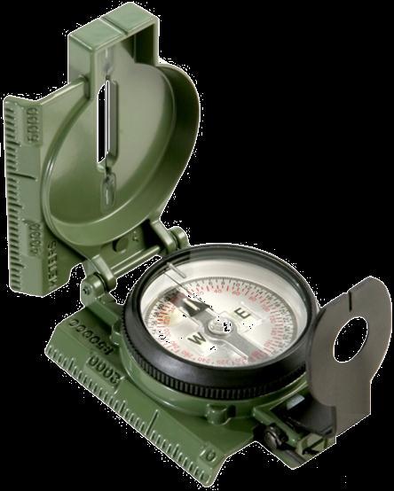
6 LENSATIC COMPASS DESCRIPTION The genuine Lensatic compass differs from the type most hikers are familiar with, the traditional "orienteering" compasses. The Lensatic, a design preferred by military forces for its precision and durability, is designed to take hyperaccurate bearings for land navigation and directing artillery fire! Preferred by military for its precision and durability, and its hyper-accuracy in land navigation and combat. Battle tested - shock, water, sand proof, and functional from -50ºF to +150ºF. Uses a retractable lens to read the bearing while simultaneously sighting an object. With the Lensatic you just point and shoot bearing one target and immediately move on to the next. Luminous Lights allow for navigation in low-light conditions and night navigation. Equipped with a magnifying lens, sight wire, and dial graduations in both degrees and mils to ensure accurate readings. Copper induction dampening system slows the rotation of the magnet without the use of liquids. Retractable lens locks the dial jewel bearing when stowed to lessen wear and tear. Employs a "Card" type compass Dial, and this makes for single handed operation. (Most magnetic "needle" type, always requires 2 hands.) A 'deep-well' design is used to allow the compass to be used globally with little or no effect in accuracy caused by a tilting compass dial. Lensatic sighting compasses are so simple and rugged and incredibly easy to use that it is no wonder they are the standard type used for navigation by the U. S. Military. STUDENT HANDBOOK 6
 but some claim to offer U.S. Government Military Lensatic compasses for just $14.")

7 LENSATIC COMPASS GENUINE or IMITATION Cheap Lensatic Copies When someone tried to buy a genuine CAMMENGA LENSATIC COMPASS from websites, they came across a whole raft of cheap imitations. Most outlets tell you they are selling Military Style Lensatic compasses (fake, inaccurate, missing features) but some claim to offer U.S. Government Military Lensatic compasses for just $14.95, which are also fake cheap imitations. Cheap copies break easily, are not accurate, have false features displayed on the compass glass face and will mislead you. The genuine lensatic compass used by the military is very durable, accurate, and easy to use. It can survive rough handling and harsh environments. Buy the Genuine Article Purchasing a genuine CAMMENGA LENSATIC COMPASS is easy, go to Visit to read about the comparison of compasses. orienteering compass vs lensatic compass. STUDENT HANDBOOK 7

8 LENSATIC COMPASS PARTS and Features of a Lensatic compass Luminous Sighting Dots Sighting Wire Floating Dial Fixed Index Line Luminous Magnetic Arrow Luminous Bezel Line Luminous Heading Bezel Sighting Slot 3. LENS REAR SITE Lens Graduated Straight Edge 1. COVER 2. BASE Lanyard Ring Thumb Loop STUDENT HANDBOOK 8


9 LENSATIC COMPASS Cover - Protects the floating dial and other parts of the compass when closed. Sighting Wire - front sight used with rear sight, for sighting landmarks for azimuth headings. Luminous Sighting Dots used in low-light condition and night navigation. Also a visual queue on aligning your body with the compass during night navigation. Graduated Straight Edge - upper half of a standard 1:50,000 scale map ruler, for measuring distances on a map. Bezel Ring device clicks when turned; full 360 rotation is 120 clicks; each click equals 3. Luminous Bezel Line Used to mark a course direction during day or night navigation. Floating Dial black scale (mils), red scale (degrees), set in a deep tub for global use. Luminous Heading to read azimuth heading in low-light or night conditions. Luminous Magnetic Arrow always points to magnetic north. Thumb Loop to hold compass with the thumb. Fixed Index Line azimuth heading. Lanyard Ring for string or rope. Base - The main body of the compass. If, for any reason, the lensatic compass were to malfunction, the base would be the piece that you would want to still work. NOTE: The only way for the compass to malfunction is for the user to misuse and abuse the compass. STUDENT HANDBOOK 9

 E = 16 (1600) S = 32 (3200) W = 48 (4800) 8.")

10 FLOATING DIAL SCALE BLACK RING Mils - is used mainly in artillery, tank, and mortar gunnery. AND is also used for very accurate azimuth land navigation Mils to a Circle Distance Between Small Marks = 20 Mils Distance Between Big Marks = 100 Mils Distance Between Numbers = 200 Mils N = 64 (6400) E = 16 (1600) S = 32 (3200) W = 48 (4800) 8.89 Mils = ½ Degree Mils = 1 Degree RED RING Degrees common unit of measure is the degree (º). 360 Degrees to a Circle Distance Between Red Marks = 5º Distance Between Big Marks = 10º Distance Between Red Numbers = 20º N = 0º E = 90º S = 180º W = 270º STUDENT HANDBOOK 10

11 FLOATING DIAL SCALE In a complete 360 circle, there are 2 pi radians. This is radians per circle. Since there is 1000 milli-radians in one radian, there are 6283 milli-radians in a circle. The US military adapted it for use with maps, artillery and numerous other things. However, the US military 'simplified' it to 6400 mils in a circle. The Russian military rounded down to 6000 mils in a circle. STUDENT HANDBOOK 11
 of ground distance. Lens Rear Site - Sighting device.")

12 LENSATIC COMPASS GRADUATED STRAIGHT EDGE Approximately 1 inch (every 13 ticks) Exactly 1 cm (every 5 ticks) Used to take distance measurements from point A to point B on maps; in conjunction with the distance bar scales on the map. ZERO NOTE When used on a 1:50,000 map, each tick mark on the edge represents 100 meters (107 yards) of ground distance. Lens Rear Site - Sighting device. Lens - used to read the dial. Rear Site - used in conjunction with the front site wire for sighting on objects. NOTE: The Lens Rear Sight also serves as a locking device and locks the dial jewel bearing to protect from wear and tear when closed. Also the rear sight must be opened more than 45 to allow dial to float freely. When traveling make sure that the rear sight is totally folded down as this will lock the floating dial and prevent vibration, as well as protect the crystal and rear sight from being damaged. STUDENT HANDBOOK 12
13 Handling and Inspecting a COMPASS When buying a new compass check... That the dial does not stick Sighting wire is not bent Glass and other parts are not broken Numbers on the dial are legible Check for accuracy along a known line of direction Discard any type of compass with more than a 3 +/- variation. Lensatic compass is accurate to a ½ degree (better when using the mils scale). When traveling make sure that the rear sight is totally folded down as this will lock the floating dial and prevent vibration, as well as protect the crystal and rear sight from being damaged. EFFECTS OF METAL AND ELECTRICITY these sources affect performance of a compass during use. 180 feet / 55 meters High tension power lines 33 feet / 10 meters Truck, car, Barbed wires 6 feet / 2 meter Hunting rifle 1 feet / ½ meter Knife, flashlight, binoculars, camera Inches / centimeters Belt buckle, paper clip, jewelry, etc. Misc distances any local geological magnetic rocks. Compasses are delicate instruments and should be cared for accordingly. A detailed inspection is required when first obtaining and using a compass. Important serviceability checks are outlined below: VISUAL INSPECTION Your compass should be opened to see that the cover glass is not broken, clouded, or cracked and that the compass dial does not stick. The front cover should be inspected to see if the cover sighting wire is missing or bent. If it is, use the center of the opening for sighting purposes, not the wire. The eyepiece should be placed flat against the cover glass. The index line on the cover glass should bisect the sight slot. Then, with the compass closed, it should be noted that the sighting wire also bisects the sight slot. This procedure will ensure that the eyepiece is not bent. Gently bend the eyepiece back into proper alignment, if necessary. Check the bezel ring around the face of the compass; it should make a distinct click as it is rotated. If it does not click, you will have to use an alternate method for night azimuth settings. MAINTENANCE The lensatic compass is built to detailed specifications that were developed in an attempt to increase its serviceable life. Adherence to very simple maintenance procedures will significantly increase the life of the lensatic compass. Maintenance procedures are outlined below: Rinse in fresh water. This is extremely important, especially after exposure to salt water. Brush off dirt and grime. Ensure the "ridges" on the bezel ring are free of dirt. Check movement of the rear sight to ensure it is free moving. STUDENT HANDBOOK 13

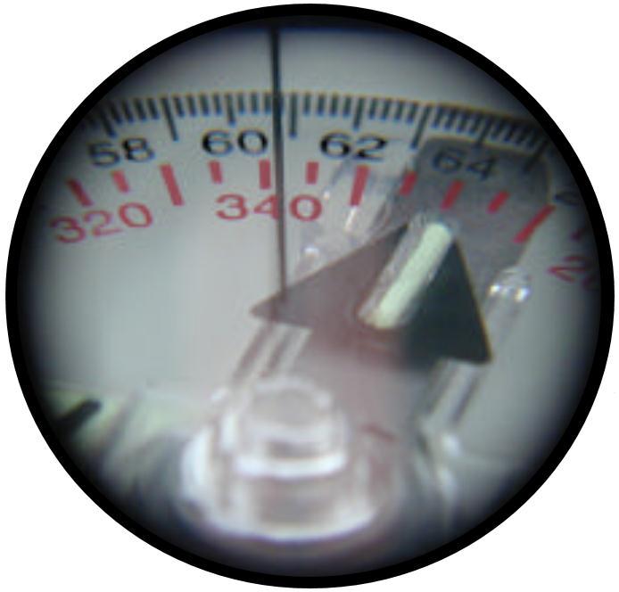
14 LENSATIC COMPASS CALIBRATION A compass in good working condition is very accurate, but it should be checked periodically on a known line of direction. This process is called compass calibration. CALIBRATION Note the calibration point azimuth. This is the known magnetic azimuth from the calibration point to a designated point. Shoot an azimuth from the calibration point to the designated point utilizing the compass-to-cheek technique (described in detail later in this handout). Ensure you check for effects on your compass from your eyeglasses, watches, rings, etc. If you wear these items in the field, ensure you wear them when calibrating your compass. Compare azimuths (LENSATIC COMPASS ERROR if there is any error.) If your compass shot an azimuth greater than the calibration point azimuth, then you must add the difference between the two azimuths (the calibration point value) to your computed magnetic azimuth. Conversely, you must also ensure you subtract this value when converting from an actual compass (magnetic) azimuth to a grid azimuth. If your compass shot an azimuth less than the calibration point azimuth, then you must subtract the difference between the two azimuths (the calibration point value) from your computed magnetic azimuth. Conversely, you must also ensure you add this value when converting from an actual compass (magnetic) azimuth to a grid azimuth. NOTE: Any bearing / azimuth heading can be used, when checking your Lensatic Compass for any errors. Also, the farther the object, the more accurate is the reading. EXAMPLE #1 Here you sight in on a pole or object that is known to be due NORTH Lensatic Compass reads 2º, LENSATIC COMPASS ERROR is POSITIVE +2º NOTE: If lensatic compass reads the same as a known pole or object bearing / azimuth heading, then there is NO ERROR. CALIBRATED / SURVEY COMPASS ROSE EXAMPLE #2 Here you sight in on a pole or object that is known to be 270º degrees Lensatic Compass reads 269º, LENSATIC COMPASS ERROR is NEGATIVE -1º STUDENT HANDBOOK 14


 Calibrated/ Surveyed Compass Rose Object 65º Read Lensatic Compass")
15 LENSATIC COMPASS CALIBRATION METHOD #1 Calibrated/ Surveyed Compass Rose OBJECT: 1. 1/4 Dowel rod, stick, or thin pole stuck in 50 feet 2. Telephone 100 yards to 1/4 mile 3. Antenna pole on top of 1/4 mile 4. Any THIN OBJECT that is far away. POLE or Stick 65º POLE or Stick Object known to be 65º heading on Compass Rose. 1. Stand in center of Compass Rose and visually align both sticks to desired heading (here it is 65º Degrees). 2. Select object aligned with sticks in distance on desired heading (here it is telephone pole at 65º Degrees). 3. Standing in center of Compass Rose, check heading to object with Lensatic Compass. (see below) Calibrated/ Surveyed Compass Rose Object 65º Read Lensatic Compass heading to OBJECT. 1. If it reads 65º Heading, NO ERROR. 2. If it reads different from 65º Heading, then compass has a - /+ ERROR. Write this - /+ ERROR on the back of the compass for reference. STUDENT HANDBOOK 15


16 LENSATIC COMPASS CALIBRATION METHOD #2 NOTE: This can be done in your backyard or local park. OBJECT: See METHOD #1, any THIN OBJECT that is far away. Object known to be 65º heading in distance. IPAD DOTS 1. Visually align both IPAD DOTS to OBJECT in distance (here it is a Telephone Pole). 2. Read IPAD compass Degrees and Mils. 3. Staying in same position, check heading to object with Lensatic Compass. CAMERA LENS HOME BUTTON Read Lensatic Compass heading to OBJECT. 1. If it reads 65º Heading, NO ERROR. 2. If it reads different from 65º Heading, then compass has a - /+ ERROR. Write this - /+ ERROR on the back of compass for reference. IPADs have gyros, accelerometers, magnetometers, sensors, and GPS, etc. This means IPAD compass apps are very accurate and easy to use. There are FREE apps out there that work. Find one that has; 1. Both True & Magnetic readings. 2. Mils reading. 3. High accuracy, less than 1º. 4. No jittering, erratic, or lagging. NOTE: you may have to try several different apps to see which one works for you. The one displayed above worked great for me. No error to known object heading, with either IPAD or LENSATIC COMPASS STUDENT HANDBOOK 16

17 LENSATIC COMPASS CALIBRATION METHOD #3 NOTE: This IPAD app (Theodolite) allows you to use the camera and compass together, so you can visually see the object and compass together. However, this IPAD app cost money. 1. Visually align Crosshairs to OBJECT in distance. Here it is a Streetlight Pole. Object known to be 65º heading in distance. 2. Read IPAD compass Degrees and Mils. 3. Staying in same position, check heading to object with Lensatic Compass. Read Lensatic Compass heading to OBJECT. 1. If it reads 65º Heading, NO ERROR. 2. If it reads different from 65º Heading, then compass has a - /+ ERROR. Write this - /+ ERROR on the back of compass for reference. STUDENT HANDBOOK 17


18 SIGHTING A LENSATIC COMPASS Compass-to-Cheek method for taking a target azimuth bearing The compass-to-cheek technique is used almost exclusively for sighting, and it is the best technique for this purpose. It is the most efficient technique for taking an accurate azimuth bearing. 1 2 STUDENT HANDBOOK 18


19 SIGHTING A LENSATIC COMPASS You want to know the heading to the water tower. So you use the Lensatic compass to sight the water tower and get the heading. 65º Heading (11.5 =1150 mils) STUDENT HANDBOOK 19


20 SIGHTING A LENSATIC COMPASS THE RIGHT WAY TO HOLD THE WRONG WAY TO HOLD STUDENT HANDBOOK 20


21 LENSATIC COMPASS Center-Hold method for taking a target azimuth bearing The center-hold technique is less precise, but is faster to use and can be used under all conditions of visibility. 1. Open the cover until it forms a straight edge with the base. 2. Pull the rear sight to the rear most position, allowing the dial to float freely. 3. Next, place your thumb through the thumb loop, form a steady base with your third and fourth fingers, and extend your index finger along the side of the compass. 4. Place the thumb of the other hand between the rear sight and the bezel ring; extend the index finger along the remaining side of the compass, and the remaining fingers around the fingers of the other hand. 5. Pull your elbows firmly into your sides; this will place the compass between your chin and your belt. 6. To measure azimuth, turn entire body toward the object, pointing the compass cover directly at the object. 7. Once you are pointing at the object, look down and read the azimuth from the fixed black index line. STUDENT HANDBOOK 21

22 LENSATIC COMPASS Center-Hold method for following an azimuth bearing 1. Using the Center-Hold method to hold the compass to your body. 2. Turn your body till desired azimuth is aligned with Black Index Line, hold this azimuth. Example 25º. 3. Without turning compass, rotate Bezel Ring till Luminous Bezel Line is aligned with North Arrow. 4. Once bezel is set leave it there. (Till you are ready to change heading, then start the process over again.) 5. Keeping the North Arrow aligned with the Luminous Bezel Line, proceed forward in the direction of the desired azimuth 25º on the Black Index Line. STEP 2 STEP 3 STUDENT HANDBOOK 22

23 THE TOPOGRAPHIC MAP Without ever having been to a particular place, and with out talking to someone who has been there, you can already know quite a lot about it with a map. A map is a graphic representation of the earth s surface drawn to scale, as seen from above. It uses colors, lines, symbols, and labels to represent features found on the ground. However, the finest maps available are worthless unless the map user knows how to read them. STUDENT HANDBOOK 23
24 TOPOGRAPHIC MAP DESCRIPTION Reading a map is a language composed of lines, colors, and symbols. Five basic colors are used for Topographic Maps. Brown (Contour Lines) Black (Man Made Features, Roads, Trails) Blue (Water Features) Green (Vegetation) Red (Highway and Land Grids) Two minor colors Pink (Built up area, civilization) Purple (Updated Map Information) Symbols are used to represent the natural and man-made features of the earth. Lines show relief and elevation; it indicates variations in terrain features and heights of natural features. Every map has Margin Information about the map. Maps come in three scale sizes; SMALL, MEDIUM, and LARGE. Which affects the amount of area covered and detail that will be shown. A map is read for four basic kinds of information. Direction Distance Position Identification Maps must be taken care of and properly folded for field use. STUDENT HANDBOOK 24


25 Map Margin Information A map could be compared to any piece of equipment, in that before it is placed into operation the user must read the instructions. It is important that you know how to read these instructions. The most logical place to begin is the marginal information and symbols, where useful information telling about the map is located and explained. All maps are not the same, so it becomes necessary every time a different map is used to examine the marginal information carefully. The top left corner of a USGS topographic map has the imprint of the authority responsible for the mapping. STUDENT HANDBOOK 25


26 Map Margin Information In the upper right corner is the complete quadrangle name. The state is also given, as may be the county. Also included is the area covered and the type of map. In the bottom right corner of the map is a Key to roads on the map. Map name and state. Date of the map - one of the most significant pieces of information available. Quadrangle location shown as a black square superimposed on a state map. STUDENT HANDBOOK 26

 Pole \"MN\" indicates the direction of the North Magnetic Pole \"GN\" (Grid")
27 At bottom center is the Map Margin Information Map scale ratio size of area covered and terrain detail. Distance bar scales show several alternative units for the measurement of distance. The contour interval. The contours are the brown lines. In the lower left corner is the credit legend, a complex of information. And the following the magnetic declination. The star indicates true north: the direction of the North (rotational) Pole "MN" indicates the direction of the North Magnetic Pole "GN" (Grid North), the Universal Transverse Mercator (UTM) grid. STUDENT HANDBOOK 27
 (1) names for adjoining quadrangle maps (in black).")
 The spherical grid, latitude and longitude, complete coordinates are given at each corner of the map.")
28 Map Margin Information Additional information is distributed around the entire map margin. (only need to know items are circled) (1) names for adjoining quadrangle maps (in black). Adjacent to corners and centers of the map sides. (2) In red are the distances by road to the nearest towns. (3) The spherical grid, latitude and longitude, complete coordinates are given at each corner of the map. (4) The UTM (in black lettering with blue tics) and the UTM grid is in kilometers. (1) (1) (1) (4) (1) (1) (3) (4) (2) (1) (1) (1) (1) STUDENT HANDBOOK 28
29 Map Scale Map scale is the relationship between distance on a map and the corresponding distance on the ground. Scale is expressed as a ratio, such as 1:24,000, and shown graphically by bar scales marked in feet and miles, or in meters and kilometers. Maps with a small scale for example, 7.5- minute maps, are often called large-scale maps because they show more detail (by covering less area) than a large bar-scale (30- x 60-minute) map. You must know the scale to determine ground distances between objects or locations on the map, the size of the area covered, and how the scale may affect the amount of detail being shown. The terms small scale, medium scale, and large scale may be confusing when read in conjunction with the number. However, if the number is viewed as a fraction, it quickly becomes apparent that 1:600,000 of something is smaller than 1:75,000 of the same thing. Therefore, the larger the number after 1:, the smaller the scale of the map. (1) Small. Maps with scales of 1:1,000,000 and smaller are used for general planning and for strategic studies. The standard small-scale map is 1:1,000,000 (1 inch = 16 miles). This map covers a very large land area at the expense of less detail. (2) Medium. Maps with scales larger than 1:1,000,000 but smaller than 1:75,000 are used for operational planning. They contain a moderate amount of detail, but terrain analysis is best done with the large-scale maps. The standard medium-scale map is 1:250,000 (1 inch = 4 miles). Medium-scale maps of 1:100,000 are also frequently encountered. (3) Large. Maps with scales of 1:75,000 and larger are used for tactical, administrative, and logistical planning. These are the maps that you as a Soldier or junior leader are most likely to encounter. The standard large-scale map is 1:50,000; however, many areas have been mapped at a scale of 1:25,000 (1 inch = 2,000 feet). Lots of detail is shown on this type of map. STUDENT HANDBOOK 29
 SOME")
 VERY")
 LOTS")
 MORE")
 LOTS OF DETAIL")
30 Map Scale Medium-scale topo map (1:150,000) SOME DETAIL Small-scale map (1:100,000,000) VERY LITTLE DETAIL Large-scale topo map (1:24,000) LOTS OF DETAIL Medium-scale map (1:250,000) MORE DETAIL Large-scale map (1:24,000) LOTS OF DETAIL STUDENT HANDBOOK 30
31 Map Symbols Symbols are used to represent the natural and man-made features of the earth. It is a map language that is simple to read and understand. BUT you must first know what the map symbols represent, in order to understand, read and speak map language to others. cem STUDENT HANDBOOK 31


32 VEGETATION Map Symbols Woods Shrub Orchard Vineyard Mangrove STUDENT HANDBOOK 32


33 SUBMERGED AREAS AND BOGS Map Symbols Marsh or swamp Submerge marsh or swamp Wood marsh or swamp Submerge wood marsh or swamp Rice field Land subject to inundation STUDENT HANDBOOK 33


34 RIVERS, LAKES, AND CANALS Intermittent stream Map Symbols Perennial lake or pond Perennial stream Intermittent lake or pond Intermittent river Dry lake Perennial river Small falls; small rapids Well or spring Large falls; large rapids Canal Dam STUDENT HANDBOOK 34


35 Map Symbols MAN-MADE FEATURES and HIGHWAY & LAND GRIDS Built-up Areas Buildings School Church Road Dirt Road Bridge Land Grids Airports Foot Bridge Landing Strip Trail Cemetery Mine Gravel Pit cem Power Lines Railroad STUDENT HANDBOOK 35


36 CONTOUR LINES Contour Interval ~ The contour interval is the distance between each contour line. The contour interval is found along the bottom edge, center of the map. Intermediate Contour ~ a brown line on a topographic map and represents a line of equal elevation. A=700 ft B=740 ft C=770 ft D=820 ft Index Contour ~ a bolder/wider brown line that has the elevation value marked at various intervals as a part of the line. Example: contour is 20 feet interval STUDENT HANDBOOK 36

37 CONTOUR LINES There is a dimension to establishing position which does depend on map reading skills. This is the vertical dimension. On a map it is referred to as relief. Knowledge of the relief of an area is extremely important to a wilderness navigator. The most graphic technique ever devised to show relief information is the contour line. If you were to walk a contour line you would never go down hill and never up hill, and eventually you would arrive back where you started. STUDENT HANDBOOK 37


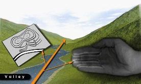
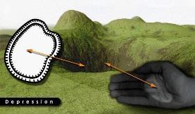
38 Five Major Ridge Hill Saddle Valley Depression Terrain Relief Features Three Minor Spur Draw Cliff Two Supplemental Cut Fill Five Major Ridge Hill Saddle Valley Depression STUDENT HANDBOOK 38


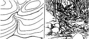
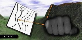
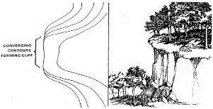
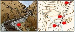
39 Three Minor Terrain Relief Features Spur Draw Cliff Two Supplemental Cut Fill STUDENT HANDBOOK 39

40 Terrain Relief Features STUDENT HANDBOOK 40

41 Map Information Direction EXPRESSING DIRECTION You need a way of expressing direction that is accurate, is adaptable to any part of the world, and has a common unit of measure. Directions are expressed as units of angular measure and direction implies a reference point. The common reference point for maps is True North, and map direction is figured in degrees from that point. Azimuths - The direction from one point to another point (either on the map or on the ground) is called an azimuth. Azimuths are given in degrees in a clockwise direction. Since there are 360 in a circle, an azimuth can be any number up to 360. East is 90, South is 180, West is 270, and North is 360. Maps are laid out with the top toward the top of the earth True North (geographic north) and map north. The side edges of the map are the only lines on the map guaranteed to run true north-south. The many north-south lines on a map give grid north. The compass needle points to magnetic north. Grid north and magnetic north usually have a few degrees difference. Neither points straight at the North Pole; that is called true north. With compass and map you can know what direction you are heading. STUDENT HANDBOOK 41
42 Map Information Direction THREE TYPES OF DIRECTION True North. A line from any point on the earth's surface to the north pole. Is represented by a star. Magnetic North. The direction to the north magnetic pole, as indicated by the north-seeking needle of a magnetic compass. The magnetic north is usually symbolized by a line ending with half of an arrowhead. Grid North. The north that is established by using the vertical grid lines on the map. Symbolized by the letters GN. Used for UTM grid by military and rescue teams for its accuracy and simplicity. G-M ANGLE. The angular difference between GN and MN. Why do we need to know all this? So that we can navigate using a map, the ground (we often forget the ground is important) and compass. You cannot follow a GN with a compass; nor can you plot a MN with a protractor. To assist you in making the conversion from MN to GN, and vice versa, a declination diagram is placed on the map margin. Remember the following. When using a map - use a protractor to measure GRID Bearings (page 46-47). Do not use the compass magnetic needle. (unless map has MN Lines see Part 2 Intermediate Land Nav) When using the ground use a Compass to Measure MAGNETIC Bearings. With GN and G-M ANGLE you can Find the MN. With MN and G-M ANGLE you can Find the GN. G - M Angle ( = 24 ) Your direction of travel STUDENT HANDBOOK 42
43 Map Information Direction CONVERSION (three ways to remember) Left to Right SUBTRACT Right to Left ADD WEST to EAST is least ( - ) SUBTRACT EAST to WEST is best ( + ) ADD When MN is to the west (left) of GN 1. MN to GN subtract G-M ANGLE 2. GN to MN add G-M ANGLE MN GN MN GN When MN is to the east (right) of GN 1. MN to GN add G-M ANGLE 2. GN to MN subtract G-M ANGLE GN MN GN MN STUDENT HANDBOOK 43
44 Map Information Direction HOW? CONVERSION (example 1) From ground to map. Left to Right Right to Left SUBTRACT ADD 1. You measure the bearing of a landmark on the ground with a compass. It is 49 MN. 2. The G-M ANGLE on the Map is So MN to GN SUBTRACT = 25 GN (Draw this on your map) From map to ground. 1. You measure the bearing of a point on the map with a protractor (page 46-47). It is 25 GN. 2. The G-M ANGLE on the Map is So GN to MN ADD = 49 MN (Put this on your compass) G - M Angle ( = 24 ) Your direction of travel STUDENT HANDBOOK 44
 From map to ground. 1. You measure the bearing of a point on the map with a protractor (page 46-47).")
45 Map Information Direction HOW? CONVERSION (example 2) From ground to map. Left to Right Right to Left SUBTRACT ADD 1. You measure the bearing of a landmark on the ground with a compass. It is 322 MN. 2. The G-M ANGLE on the Map is 9 3. So MN to GN ADD = 331 GN (Draw this on your map) From map to ground. 1. You measure the bearing of a point on the map with a protractor (page 46-47). It is 331 GN. 2. The G-M ANGLE on the Map is 9 3. So GN to MN SUBTRACT = 322 MN (Put this on your compass) G - M Angle 14-5 = 9 Your direction of travel STUDENT HANDBOOK 45
 by converting the protractor GN to a MN for the compass. 3.")
46 Map Information Direction PROTRACTOR 1. With a protractor the map does NOT have to be oriented. 2. It is used to calculate direction from map to ground (compass) by converting the protractor GN to a MN for the compass. 3. It is used for Plotting azimuths Plotting position Plotting UTM coordinates NOTE - If you have MN LINES drawn on the map, you can align the protractor to a MN LINE, get the MN azimuth on the protractor and you DO NOT have to do any MN conversions. (see Part 2 Intermediate Land Nav) STUDENT HANDBOOK 46
 From map to ground. 1.")
 on the map. 2.")
.")


47 Map Information Direction PROTRACTOR (with a protractor the map does NOT have to be oriented) From map to ground. 1. You are in thick woods and cannot see any landmarks. But you decide to go to a hill (A) on the map. 2. With protractor aligned with GRID LINES drawn on the map and the center of the protractor aligned on your map position (you are here). 3. You see that the azimuth is 29 or 520 MILS. See below for closer view A 4. Convert this to MN azimuth and put this on your compass. NOTE: If you have MN LINES drawn on the map, align the protractor to a MN LINE, get the MN azimuth and you DON T have to do MN conversions. (See PART 2 Intermediate Land Navigation) you are here STUDENT HANDBOOK 47

 With compass & map: 1. Lay the compass on the MN line on the map. 2.")
48 Map Information - Direction Orienting the Map with the Landscape (MN and True North) TECHNIQUE # 1 (True North) 1. Identify several landmarks on the map and on the terrain. 2. Visually orient the map landmarks with the terrain landmarks. 3. The map is oriented to True North. TECHNIQUE # 2 (Magnetic North) With compass & map: 1. Lay the compass on the MN line on the map. 2. Rotate the map and compass together until the compass bearing reads 0 degrees Magnetic North (compass and MN line on the map are aligned / parallel). 3. The map is oriented to MN. STUDENT HANDBOOK 48
 TECHNIQUE # 3 (True North) 1.")


, map is oriented to TRUE NORTH. MN 11.")
 when your position on the map is known. 1.")

49 Map Information - Direction Orienting the Map with the Landscape (MN and True North) TECHNIQUE # 3 (True North) 1. Find Magnetic Declination value in the map margin (bottom left corner), example East Place compass edge on edge of map North/South line with front of compass facing top of map. 3. Rotate map and compass together until North Arrow is 11.5 east of Black Index Line. Note: Black Index Line is aligned with ( = ), map is oriented to TRUE NORTH. MN 11.5 East of North correct for 1990 and moves easterly by 0.1 annually. TECHNIQUE # 4 (Magnetic North) when your position on the map is known. 1. Select a terrain feature on the ground that you can find on the map, example the HILL. 2. With the compass, sight the azimuth to the HILL(295 ) from your position ( ). 3. Align the compass edge through the HILL and your position ( ). 4. Rotate map and compass together until 295 is aligned with Black Index Line. Map is oriented MN. HILL HILL STUDENT HANDBOOK 49

50 Map Information - Distance The relationship between map and ground distance is the function of the bar scale. The bar scale looks like a small ruler and usually has 3 to 4 bar scales; feet, miles, meters, and kilometers. The ability to determine distance on a map, as well as on the earth s surface, is an important factor in planning and executing safe, practical routes. The map scale of 1:xx,xxx means that one unit of measure on the map is equal to xx,xxx units of the same measure on the ground. A map scale of 1:25,000 means that one unit of measure on the map is equal to 25,000 units of the same measure on the ground. On map 1 inch = 25,000 inches (2083 feet, 694 yards) on the ground. On map 1 cm = 25,000 cm (250 meters, ¼ kilometer) on the ground. A map scale of 1:100,000 means that one unit of measure on the map is equal to 100,000 units of the same measure on the ground. On map 1 inch = 100,000 inches (8333 feet, 2778 yards, 1¾ mile) on the ground. On map 1 cm = 100,000 cm (1000 meters, 1 kilometer) on the ground. Example below shows the navigator using centimeters (cm) as a measurement, therefore the map 10cm measurement is equal to 250,000cm on the ground. 10cm x 25,000 = 250,000cm (2.5 Km) 3.94in x 25,000 = 98,500in (1.55 miles) B A B A STUDENT HANDBOOK 50
51 Map Information - Position Finding one s position on a map in the usual sense, such as at the intersection of two compass bearings, is more a matter of compass technique than of map reading skills... BUT... It is possible to locate your POSITION on a map without a compass, by land feature and map association. It is IMPOSSIBLE TO BE TOTALLY LOST. Finding your location is a process of narrowing down the options until you can determine a point on a map. By determining the lay of the land and finding prominent features, then relating them to your map, the narrowing-down process will not take long. Landmarks can be anything that you recognize as being on the map. Classically these are hill tops, but you can use the intersection of two roads, a building such as a power grid substation, the abrupt edge of a ridge, the edge of an island, the bend in a trail, anything that you can recognize as being on the map and that you can see. There is a second dimension to establishing position which does depend on map reading skills. This is the vertical dimension. On a map it is referred to as relief. Knowledge of the relief of an area is extremely important to a wilderness navigator. The most graphic technique ever devised to show relief information is the contour line. If you were to walk a contour line you would never go down hill and never up hill, and eventually you would arrive back where you started. Navigation is not about finding yourself after you are lost (although that s what happens sometimes); navigation is about keeping track of your POSITION as you move away from a known point. As you move you have to remain cognizant of the terrain you are leaving, of the terrain you are passing, and of the terrain that is coming up. STUDENT HANDBOOK 51


52 Map Information - Identification The identification of significant features, both natural and man-made, is partly a matter of knowing the language of maps. One category of map language is lines. In addition to showing contour relief, lines are used to portray roads, trails, railroads, power lines, and drainage features. Another category of map language is composed of various picture symbols. A third part of map language is color. If part of identification is in knowing the language of maps, the rest is a problem of interpretation. What is the relationship among certain lines, symbols, and colors? Reading contour lines is literally reading between the lines. Contour lines represent the shape of the terrain only at specified intervals. The user must be aware that what lies between may be quite different. There could be rugged terrain, vertical bluffs, or deep ravines that might not be shown. CONTOUR LINES Contour Lines on a map Do not show everything. Scan the Landscape, read between the lines. A river may be drawn some what straight on a map, but the terrains actual river meanders, with many curves, turns, and with wide and narrow banks. What a topographic map shows is as accurate as possible, BUT can give you a false sense of what you might mentally think what is ahead of you and what actually is shown on an aerial photo map and actual land features. STUDENT HANDBOOK 52
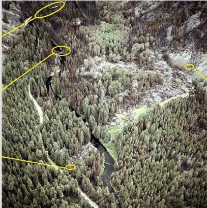
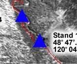
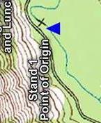

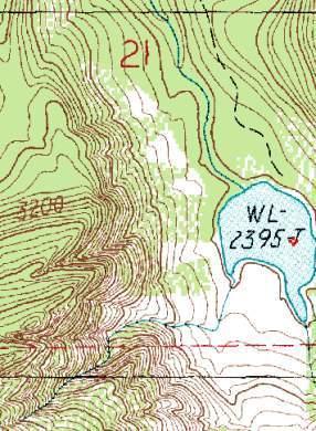

53 Map Information Identification What a Topo map, Aerophoto map, And actual Land features show TOPO MAP AERIAL PHOTO LAND STUDENT HANDBOOK 53


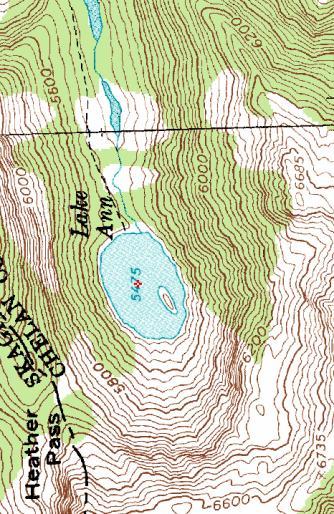
54 Map Information Identification What a Topo map and actual Land features show Compare the next few pictures with this map, to get view point perspective of what you see on this map and what you see on the landscape in front of you. View 1 View 2 STUDENT HANDBOOK 54
55 Map Information Identification What a Topo map and actual Land features show View 1 View 2 STUDENT HANDBOOK 55


56 Map Information Identification What a Topo map and actual Land features show Note: here the map is turned upside down so you can get a better perspective View 2 View 1 View 1 View 1 View 2 View 2 STUDENT HANDBOOK 56


57 Map Folding and Map Care Maps should be correctly folded. Maps should be folded to make them small enough to be carried and still be available for use without having to unfold them entirely. After a map has been folded it should be placed in a folder for protection. This will prevent the corners and edges of the map from wearing out and tearing easily when opened. It is hard to navigate accurately with a dirty, grimy, wet or damaged map. Take care of your map and it will take care of you. Most maps are printed on paper and require protection from water, mud, weather, and tearing. Whenever possible, a map should be carried in a waterproof packet to prolong its life. Waterproofing maps. All members of the group should know the map s location at all times. Marking a map. If it is necessary to mark a map, use light lines so that they may be erased without smearing or smudging. If the margins of the map must be trimmed note any marginal information which may be needed, such as grid data or magnetic declination data, on the back of the map. Special care should be taken of a map that is being used in any situation, especially in a small group; the mission may depend on that map. STUDENT HANDBOOK 57


58 WELCOME TO LAND NAVIGATION CLASS Map Folding Technique # 1 Technique # 3 Technique # 2 After a map has been folded, it should be pasted in a folder for protection. Apply adhesive to the back of the segments corresponding to A, F, L, and Q NOTE: It is suggested that before attempting to cut and fold a map in the manner illustrated above, make a practice cut and fold with a piece of paper. STUDENT HANDBOOK 58
59 THE END OF LAND NAVIGATION PRESENTATION PART STUDENT HANDBOOK 59
UNITED STATES MARINE CORPS FIELD MEDICAL TRAINING BATTALION Camp Lejeune, NC
 UNITED STATES MARINE CORPS FIELD MEDICAL TRAINING BATTALION Camp Lejeune, NC 28542-0042 FMST 206 Land Navigation TERMINAL LEARNING OBJECTIVE 1. Given a military topographic map, protractor, and objective,
Land Navigation / Map Reading
 Land Navigation / Map Reading What is the Field Manual for map reading and land navigation? FM 3-25.26 What are the basic colors of a map, and what does each color represent? Black - Indicates cultural
CHAPTER 3 MARGINAL INFORMATION AND SYMBOLS
 CHAPTER 3 MARGINAL INFORMATION AND SYMBOLS A map could be compared to any piece of equipment, in that before it is placed into operation the user must read the instructions. It is important that you, as
Lab #4 Topographic Maps and Aerial Photographs
 Lab #4 Topographic Maps and Aerial Photographs Purpose To familiarize you with using topographic maps. Visualizing the shape of landforms from topographic maps is an essential skill in geology. Proficiency
BACKGROUND INFORMATION
 Build an Island INTRODUCTION For this assignment, you will be creating a topographic map and three-dimensional model of a fictional island that you have designed. You will start by exploring some basic
CONVERTING BEARINGS CONT. Grid to Magnetic subtract (GMS - grand ma sleeps) 1 BACK BEARINGS CONVERTING BEARINGS
 1 BACK BEARINGS CONVERTING BEARINGS") CONVERTING BEARINGS CONT 2 Grid to Magnetic subtract (GMS - grand ma sleeps) ^Khd,YhE^>E h^dz>/ezdzd^z/' Es/'d/KE CONVERTING BEARINGS 1 BACK BEARINGS 3 Magnetic to Grid add (MGA - my great aunt) Back Bearings
CONVERTING BEARINGS CONT 2 Grid to Magnetic subtract (GMS - grand ma sleeps) ^Khd,YhE^>E h^dz>/ezdzd^z/' Es/'d/KE CONVERTING BEARINGS 1 BACK BEARINGS 3 Magnetic to Grid add (MGA - my great aunt) Back Bearings
Introduction to Aerial Photographs and Topographic maps (Chapter 3)
") GEOLOGY 306 Laboratory Instructor: TERRY J. BOROUGHS NAME: Introduction to Aerial Photographs and Topographic maps (Chapter 3) For this assignment you will require: a calculator and metric ruler. Objectives:
GEOLOGY 306 Laboratory Instructor: TERRY J. BOROUGHS NAME: Introduction to Aerial Photographs and Topographic maps (Chapter 3) For this assignment you will require: a calculator and metric ruler. Objectives:
Important Questions. Surveying Unit-II. Surveying & Leveling. Syllabus
 Surveying Unit-II Important Questions Define Surveying and Leveling Differentiate between Surveying and Leveling. Explain fundamental Principles of Surveying. Explain Plain and Diagonal Scale. What is
ENVI.2030L Topographic Maps and Profiles
 Name ENVI.2030L Topographic Maps and Profiles I. Introduction A map is a miniature representation of a portion of the earth's surface as it appears from above. The environmental scientist uses maps as
Mapping The Study Area
 While on the beach you will need to take some measurements to show where the study area is relative to the rest of the world and to show what is inside the study area. Once the measurements have been taken,
Chapter 6 Navigation and Field Mapping
 Chapter 6 Navigation and Field Mapping In this chapter you will learn about: Orienting maps Measuring a bearing on a map Plotting points on a map using latitude/longitude Plotting points on a map using
Introduction to Aerial Photographs and Topographic maps (Chapter 7, 9 th edition) or (chapter 3, 8 th edition)
 or (chapter 3, 8 th edition)") GEOLOGY 306 Laboratory Instructor: TERRY J. BOROUGHS NAME: Introduction to Aerial Photographs and Topographic maps (Chapter 7, 9 th edition) or (chapter 3, 8 th edition) For this assignment you will require:
GEOLOGY 306 Laboratory Instructor: TERRY J. BOROUGHS NAME: Introduction to Aerial Photographs and Topographic maps (Chapter 7, 9 th edition) or (chapter 3, 8 th edition) For this assignment you will require:
Surveying & Measurement. Detail Survey Topographic Surveying
 Surveying & Measurement Detail Survey Topographic Surveying Introduction Mapping surveys are made to determine the relief of the earth s surface and locate critical points on it. to determine the locations
Topographic Maps. Contour Lines
 Topographic Maps Our first task today will consist of locating ourselves with the help of a topographic map. GPS units that can tell you the location of any Dunkin' Donuts within a five mile radius. Paper
CONTOURS SURVEYING 1 CE 215 CHAPTER -3- Ishik University / Sulaimani Civil Engineering Department 12/7/2017. Ishik University / Sulaimani
 Civil Engineering Department SURVEYING 1 CE 215 CHAPTER -3- CONTOURS 1 2 1 3 4 2 PURPOSE OF CONTOURING Contour survey is carried out at the starting of any engineering project such as a road, a railway,
Contour An imaginary line on the ground surface joining the points of equal elevation is known as contour.
 Contour An imaginary line on the ground surface joining the points of equal elevation is known as contour. In other words, contour is a line in which the ground surface is intersected by a level surface
AutoCAD 2016 for Civil Engineering Applications
 Introduction to AutoCAD 2016 for Civil Engineering Applications Learning to use AutoCAD for Civil Engineering Projects Nighat Yasmin Ph.D. SDC P U B L I C AT I O N S Better Textbooks. Lower Prices. www.sdcpublications.com
Lab #8: Topographic Map Lab
 NAME: LAB TIME: TA NAME: Lab #8: Topographic Map Lab Topography is the shape of the land. Topographic maps are used to aid in the visualization of the shape of the land. Topographic maps include the accurate
Earth Sciences 089G Short Practical Assignment #4 Working in Three Dimensions
 Earth Sciences 089G Short Practical Assignment #4 Working in Three Dimensions Introduction Maps are 2-D representations of 3-D features, the developers of topographic maps needed to devise a method for
Module 2: Mapping Topic 3 Content: Topographic Maps Presentation Notes. Topographic Maps
 Topographic Maps 1 Take a few moments to study the map shown here of Isolation Peak, Colorado. What land features do you notice? Do you thinking hiking through this area would be easy? Did you see the
Photo Scale The photo scale and representative fraction may be calculated as follows: PS = f / H Variables: PS - Photo Scale, f - camera focal
 Scale Scale is the ratio of a distance on an aerial photograph to that same distance on the ground in the real world. It can be expressed in unit equivalents like 1 inch = 1,000 feet (or 12,000 inches)
Legal Description & Site Plan Requirements and Layouts
 Legal Description & Site Plan Requirements and Layouts Plot Plan * A plot plan shows the location of a house from an aerial view. * The site plan, also known as a plot or lot plan includes: 1. Site plan
PRE-LAB for: Introduction to Aerial Photographs and Topographic maps (Ch. 3)
") GEOLOGY 306 Laboratory Instructor: TERRY J. BOROUGHS NAME: PRE-LAB for: Introduction to Aerial Photographs and Topographic maps (Ch. 3) For this assignment you will require: a calculator and metric ruler.
GEOLOGY 306 Laboratory Instructor: TERRY J. BOROUGHS NAME: PRE-LAB for: Introduction to Aerial Photographs and Topographic maps (Ch. 3) For this assignment you will require: a calculator and metric ruler.
Engineering Surveying -1 CE212 Contouring Lectures. Lecture 2016, November 29 th Muhammad Noman
 Engineering Surveying -1 CE212 Contouring Lectures Lecture 2016, November 29 th Muhammad Noman Contour An Imaginary line on the ground surface joining the points of equal elevation is known as contour.
Maps and map interpretation An introduction for geoscientists
 Maps and map interpretation An introduction for geoscientists Produced by the University of Derby in conjunction with UKOGL Aims This teaching package provides an introduction to maps and how to identify
Markville Secondary School Geography Department
 Markville Secondary School Geography Department CGC1D1 Geography of Canada PERFORMANCE TASK - UNITS 1 AND 2 February 2012 DUE DATE: Parent Signature: CONTOUR MAP AND MODEL The performance task for the
Department of Civil and Environmental Engineering
 Department of Civil and Environmental Engineering CEE213L Surveying & Introduction to GIS Lab SURVEYING LABORATORY NORTH SOUTH UNIVERSITY Center of Excellence in Higher Education The First Private University
COPYRIGHTED MATERIAL. Contours and Form DEFINITION
 1 DEFINITION A clear understanding of what a contour represents is fundamental to the grading process. Technically defined, a contour is an imaginary line that connects all points of equal elevation above
Engineering Graphics Essentials with AutoCAD 2015 Instruction
 Kirstie Plantenberg Engineering Graphics Essentials with AutoCAD 2015 Instruction Text and Video Instruction Multimedia Disc SDC P U B L I C AT I O N S Better Textbooks. Lower Prices. www.sdcpublications.com
A vibration is one back-and-forth motion.
 Basic Skills Students who go to the park without mastering the following skills have difficulty completing the ride worksheets in the next section. To have a successful physics day experience at the amusement
ENGINEERING GRAPHICS ESSENTIALS
 ENGINEERING GRAPHICS ESSENTIALS with AutoCAD 2012 Instruction Introduction to AutoCAD Engineering Graphics Principles Hand Sketching Text and Independent Learning CD Independent Learning CD: A Comprehensive
Title: How steep are those hills? Engineering Grade: Estimated Time: 3 hours (2 days) Groups: 3 to 4 students
 Groups: 3 to 4 students") Title: How steep are those hills? Engineering Grade: 10-12 Estimated Time: 3 hours (2 days) Groups: 3 to 4 students Synopsis: Students will be able to understand the concept of surveying and mapping ground
Title: How steep are those hills? Engineering Grade: 10-12 Estimated Time: 3 hours (2 days) Groups: 3 to 4 students Synopsis: Students will be able to understand the concept of surveying and mapping ground
Suveying Lectures for CE 498
 Suveying Lectures for CE 498 SURVEYING CLASSIFICATIONS Surveying work can be classified as follows: 1- Preliminary Surveying In this surveying the detailed data are collected by determining its locations
Gradient and Rate of Change
 Name: 1. Base your answer(s) to the following question(s) on the topographic map shown below. Letters A, B, C, and D represent locations on Earth s surface. The symbol marks the highest elevation on Patty
1. The topographic map below shows a depression contour line on Earth's surface.
 1. The topographic map below shows a depression contour line on Earth's surface. Points A, B, C, and D represent surface locations. Contour line elevations are in feet. Which profile best shows the topography
Shoe Box Activity Constructing a Topographic Map
 Shoe Box Activity Constructing a Topographic Map Background Information All maps are models of some feature of the real world. The kind of map oen used by scientists is called a contour or topographic
User Manual. This User Manual will guide you through the steps to set up your Spike and take measurements.
 User Manual (of Spike ios version 1.14.6 and Android version 1.7.2) This User Manual will guide you through the steps to set up your Spike and take measurements. 1 Mounting Your Spike 5 2 Installing the
Lesson 8: Surveying the Forest
 Lesson 8: Surveying the Forest TEACHER: SCHOOL: GRADE LEVEL: 9-12 TASKS/COMPETENCIES ANR8046.172 Set up and operate a transit level and rod. ANR8046.173 Read a rod and a level to calculate slope. ANR8046.174
A Rapid Photo Point Monitoring Method
 A Rapid Photo Point Monitoring Method Pat Reece, Prairie & Montane Enterprises patreece@prairieme.com Tonya Haigh, National Drought Mitigation Center thaigh2@unl.edu Goal: To document the effects that
31, The following isoline map shows the variations in the relative strength of Earth's magnetic field from 1 (strong) to 11 (weak).
 to 11 (weak).") 31, The following isoline map shows the variations in the relative strength of Earth's magnetic field from 1 (strong) to 11 (weak). 33. The following four temperature field maps represent the same region
31, The following isoline map shows the variations in the relative strength of Earth's magnetic field from 1 (strong) to 11 (weak). 33. The following four temperature field maps represent the same region
USER MANUAL. Latitude Spotting Scopes SM11033, SM11033T SM11034, SM11034T
 USER MANUAL Latitude Spotting Scopes SM11033, SM11033T SM11034, SM11034T ABOUT SIGHTMARK Sightmark offers a wide range of products that include red dot scopes, reflex sights, rangefinders, riflescopes,
ILLINOIS ARMY NATIONAL GUARD Marseilles Training Center 1700 Army Road Marseilles, IL
 ILLINOIS ARMY NATIONAL GUARD Marseilles Training Center 1700 Army Road Marseilles, IL 61341-9535 Land Navigation Course 102 Ph. (815)795-5701 INDEX Chapter 1 GENERAL Page Guidance for OIC/Test Administrator
NREM 345 Week 2, Material covered this week contributes to the accomplishment of the following course goal:
 NREM 345 Week 2, 2010 Reading assignment: Chapter. 4 and Sec. 5.1 to 5.2.4 Material covered this week contributes to the accomplishment of the following course goal: Goal 1: Develop the understanding and
Problem Solving with Length, Money, and Data
 Grade 2 Module 7 Problem Solving with Length, Money, and Data OVERVIEW Module 7 presents an opportunity for students to practice addition and subtraction strategies within 100 and problem-solving skills
This little piece here I created is some of the scraps and then samples I was making for today s show. And these are wonderful for doing like
 Hey everybody, welcome back to Man Sewing. This is Rob and today on the show, I m going to teach you how I like to do my curve piecing. Now I can t take all the credit for this. Ricky Tims, a good friend
Using the Ruler Tool to Keep Your Tracks Straight Revised November 2008
 Using the Ruler Tool to Keep Your Tracks Straight Revised November 2008 Suppose you had to lay a section of track 8000 feet (2424m) long. The track will include a station and several industrial sidings.
Don't Shatter My Image
 Don't Shatter My Image Name Physics - Reflection Lab This lab will locate images and relate the size of the angle at which the ray of light hits the plane mirror to the size of the angle at which the light
MUDGUN Drywall Finishing System
 Watch the demonstration video online at hydetools.com MUDGUN Drywall Finishing System Quick Start Guide Hyde Tools, Inc. / A Hyde Group Company / 800-872-4933 / custrelations@hydetools.com / hydetools.com
Robotics Links to ACARA
 MATHEMATICS Foundation Shape Sort, describe and name familiar two-dimensional shapes and three-dimensional objects in the environment. (ACMMG009) Sorting and describing squares, circles, triangles, rectangles,
Markville Secondary School Geography Department
 Markville Secondary School Geography Department CGC1D1 Geography of Canada PERFORMANCE TASK - UNIT 1 AND 2 DUE DATE: SEPTEMBER 2011 Parent Signature: CONTOUR MAP AND MODEL The performance task for Geography
How to Make a Template
 Page 1 of 10 How to Make a Template TOOL LIST: Template Material: Templates can be made of different materials but we prefer that you use our template material. We offer rolls that are 50ft x 52in and.007
Enhanced Instructional Transition Guide
 Enhanced Instructional Transition Guide / Unit 07: Suggested Duration: 9 days Unit 07: Measurement (15 days) Possible Lesson 01 (9 days) Possible Lesson 02 (3 days) Possible Lesson 03 (3 days) Possible
MetalliScanner 6.0 Components
 MetalliScanner 6.0 Components 1. Mode Switch 2. Calibration Switch 3. Crosshairs 4. Liquid Crystal Display 5. Battery Compartment LCD Components 1. Depth Bars 2. Depth Numbers 3. Magnetic Icon 4. Low Battery
Chapter 2. Statistics and Measurement
 www.ck12.org Chapter 2. Statistics and Measurement 2.1 Measuring Length Introduction The Tomato Plants Tania and her brother Alex have decided to plant a vegetable garden. They are interested in eating
Engineering Graphics. Class 2 Drafting Instruments Mohammad Kilani
 Engineering Graphics Class 2 Drafting Instruments Mohammad Kilani Drafting Instruments A Design is as good as its instruments A engineering drawing is a highly stylized graphic representation of an idea.
TECHNICAL INFORMATION Traffic Template Catalog No. TT1
 Copyright 2016 by SIRCHIE All Rights Reserved. TECHNICAL INFORMATION Traffic Template Catalog No. TT1 INTRODUCTION Your SIRCHIE Traffic Template is a versatile police tool designed to make even the most
MAPPING YOUR STREAM. TIME REQUIRED 50 minutes in Field 50 minutes in Classroom 50 minutes Homework
 OUR MAPPING YOUR STREAM STREAM ACTIVITY SUMMARY Students will draft a cross-sectional profile of the stream and measure the velocity of the current. They will use both of these to calculate the discharge
Section E NSPS MODEL STANDARDS FOR TOPOGRAPHIC SURVEYS Approved 3/12/02
 Section E NSPS MODEL STANDARDS FOR TOPOGRAPHIC SURVEYS Approved 3/12/02 1. INTRODUCTION This standard is written to provide the professional surveyor (Surveyor) and the client with a guideline for producing
Volume 1 - Module 6 Geometry of Aerial Photography. I. Classification of Photographs. Vertical
 RSCC Volume 1 Introduction to Photo Interpretation and Photogrammetry Table of Contents Module 1 Module 2 Module 3.1 Module 3.2 Module 4 Module 5 Module 6 Module 7 Module 8 Labs Volume 1 - Module 6 Geometry
Introduction to Computer Science with MakeCode for Minecraft
 Introduction to Computer Science with MakeCode for Minecraft Lesson 3: Coordinates This lesson will cover how to move around in a Minecraft world with respect to the three-coordinate grid represented by
East Bay Municipal Utility District. Study Guide for Survey Technician I
 East Bay Municipal Utility District Study Guide for Survey Technician I Summer 2018 TABLE OF CONTENTS PAGE Introduction... 1 Scoring... 1 Visual Perception... 2 Sample Questions 1-2... 2 Reading and Interpreting
Driver Education Classroom and In-Car Curriculum Unit 3 Space Management System
 Driver Education Classroom and In-Car Curriculum Unit 3 Space Management System Driver Education Classroom and In-Car Instruction Unit 3-2 Unit Introduction Unit 3 will introduce operator procedural and
NAVIGATION HANDBOOK Prepared for the HRCR Clubmans Rally Championship
 NAVIGATION HANDBOOK Prepared for the HRCR Clubmans Rally Championship INTRODUCTION This Rally Navigation Handbook has been prepared as a handy reference document, to give novice navigators an insight into
Lomax Mouthpiece Measuring Kit Instructions
 Lomax Mouthpiece Measuring Kit Instructions www.lomaxclassic.com www.votawtool.com #2860 Mouthpiece Measuring Kit Instructions Page 2 LOMAX CLASSIC Mouthpiece Measuring Kit Instructions Your mouthpiece
Chapter 3: Assorted notions: navigational plots, and the measurement of areas and non-linear distances
 : navigational plots, and the measurement of areas and non-linear distances Introduction Before we leave the basic elements of maps to explore other topics it will be useful to consider briefly two further
TRIMLINE CANOPY 10' x 20'
 TRIMLINE CANOPY 10' x 20' Instructions for Assembly Video instructions are available on our website! Go to: flourishdisplays.com/instructions or scan this code with your QR Code Reader App for a direct
Measuring in Centimeters
 MD2-3 Measuring in Centimeters Pages 179 181 Standards: 2.MD.A.1 Goals: Students will measure pictures of objects in centimeters using centimeter cubes and then a centimeter ruler. Prior Knowledge Required:
Follow the Map. Practice the 7 and 0 flash cards for 5 minutes. Do Speed Drill 13 on page 67. Record your score in the graph on page 60.
 13 Count by fourths to 3. Practice the 7 and 0 flash cards for 5 minutes. Do Speed Drill 13 on page 67. Record your score in the graph on page 60. Read to your teacher. 6.5 9 402,003 + = = 1 < 1 480,506
Written By: Brett Hartt
 Replace the battery in your ipad 3 4G. Written By: Brett Hartt ifixit CC BY-NC-SA www.ifixit.com Page 1 of 36 INTRODUCTION When your ipad can't stay awake for longer than a few hours, it is time to replace
ENGINEERING GRAPHICS ESSENTIALS
 ENGINEERING GRAPHICS ESSENTIALS Text and Digital Learning KIRSTIE PLANTENBERG FIFTH EDITION SDC P U B L I C AT I O N S Better Textbooks. Lower Prices. www.sdcpublications.com ACCESS CODE UNIQUE CODE INSIDE
Using Dynamic Views. Module Overview. Module Prerequisites. Module Objectives
 Using Dynamic Views Module Overview The term dynamic views refers to a method of composing drawings that is a new approach to managing projects. Dynamic views can help you to: automate sheet creation;
Written By: Walter Galan
 ipad 4 CDMA SIM Board Replacement Replace the SIM Board in your ipad 4 CDMA. Written By: Walter Galan ifixit CC BY-NC-SA www.ifixit.com Page 1 of 33 INTRODUCTION Use this guide to replace the SIM Board.
FIELD FOLDER TRAINING SEMINAR
 FIELD FOLDER TRAINING SEMINAR Copyright 2007 Double Equipment Notice: Information contained here is for educational proposes only and is not to intended replace the original equipment manufactures instructions.
ipad 3 4G Home Button Control Board Replacement
 ipad 3 4G Home Button Control Board Replacement Replace the home button control board in your ipad 3. Written By: Brett Hartt ifixit CC BY-NC-SA www.ifixit.com Page 1 of 28 INTRODUCTION This guide will
ISHR-M111 MAGNETIC ROCKWELL HARDNESS TESTER OPERATION MANUAL
 MN-ISHR-M-E www.insize.com ISHR-M MAGNETIC ROCKWELL HARDNESS TESTER OPERATION MANUAL Attention This Instruction Manual shall be carefully read through in prior to use of the apparatus to clearly understand
Summer Solutions Common Core Mathematics 4. Common Core. Mathematics. Help Pages
 4 Common Core Mathematics 63 Vocabulary Acute angle an angle measuring less than 90 Area the amount of space within a polygon; area is always measured in square units (feet 2, meters 2, ) Congruent figures
Folding Activity 3. Compass Colored paper Tape or glue stick
 Folding Activity 3 Part 1 You re not done until everyone in your group is done! If you finish before someone else, help them finish before starting on the next part. You ll need: Patty paper Ruler Sharpie
Reflection of Light, 8/8/2014, Optics
 Grade Level: 8 th Grade Physical Science Reflection of Light, 8/8/2014, Optics Duration: 2 days SOL(s): PS.9 The student will investigate and understand the characteristics of transverse waves. Key concepts
LESSON 1: UNDERSTANDING CONSTRUCTION DRAWINGS
 LESSON 1: UNDERSTANDING CONSTRUCTION DRAWINGS INTRODUCTION In this lesson, you ll learn about the different types of drawings used in the construction industry, and how to read floor plans, section drawings,
DeltaCad and Your Cylinder (Shepherd s) Sundial Carl Sabanski
 Sundial Carl Sabanski") 1 The Sundial Primer created by In the instruction set SONNE and Your Cylinder Shepherd s Sundial we went through the process of designing a cylinder sundial with SONNE and saving it as a dxf file. In
1 The Sundial Primer created by In the instruction set SONNE and Your Cylinder Shepherd s Sundial we went through the process of designing a cylinder sundial with SONNE and saving it as a dxf file. In
CHAPTER 8 AERIAL PHOTOGRAPHS
 CHAPTER 8 AERIAL PHOTOGRAPHS An aerial photograph is any photograph taken from an airborne vehicle (aircraft, drones, balloons, satellites, and so forth). The aerial photograph has many uses in military
Finished size 52 x 26. Over the River depicts the cherished childhood memories of celebrating life and families together.
 Over the River Finished size 52 x 26 Over the River depicts the cherished childhood memories of celebrating life and families together. In this Embroidery Workshop students will learn Claudia s technique
Written By: Sam Lionheart
 Replace the SIM Board in your ipad 4 GSM. Written By: Sam Lionheart ifixit CC BY-NC-SA www.ifixit.com Page 1 of 29 INTRODUCTION Use this guide to replace the SIM Board. TOOLS: SIM Card Eject Tool (1) iopener
PHOTOGRAMMETRY STEREOSCOPY FLIGHT PLANNING PHOTOGRAMMETRIC DEFINITIONS GROUND CONTROL INTRODUCTION
 PHOTOGRAMMETRY STEREOSCOPY FLIGHT PLANNING PHOTOGRAMMETRIC DEFINITIONS GROUND CONTROL INTRODUCTION Before aerial photography and photogrammetry became a reliable mapping tool, planimetric and topographic
Written By: Walter Galan
 ipad 2 CDMA Camera Bracket Replacement Replace the camera bracket in your ipad 2 CDMA. Written By: Walter Galan ifixit CC BY-NC-SA www.ifixit.com Page 1 of 29 INTRODUCTION Use this guide to replace the
3. The dimensioning SYMBOLS for arcs and circles should be given:
 Draft Student Name: Teacher: District: Date: Wake County Test: 9_12 T and I IC61 - Drafting I Test 2 Description: 4.08 Dimensioning Form: 501 1. The MINIMUM amount of space between two, ADJACENT DIMENSION
ipad 2 GSM Home Button Assembly Replacement
 ipad 2 GSM Home Button Assembly Replacement This guide will show you how to replace the home button assembly in your ipad 2. Written By: Scott Head ifixit CC BY-NC-SA www.ifixit.com Page 1 of 29 INTRODUCTION
PanelKeeper GL1500 Kit
 Rudy's ** Removable side panel cover retainer system ** PanelKeeper GL1500 Kit Installs in about 10 minutes per side - No tools required! Both sides included Prevents loss of detachable panels Stop losing
Forest Inventory System. User manual v.1.2
 Forest Inventory System User manual v.1.2 Table of contents 1. How TRESTIMA works... 3 1.2 How TRESTIMA calculates basal area... 3 2. Usage in the forest... 5 2.1. Measuring basal area by shooting pictures...
Owner s Purchase Record OPERATOR S MANUAL. 1 Orientation... Page(s): 1. 2 Magnetic Declination Azimuth Measurement... 7
: 1. 2 Magnetic Declination Azimuth Measurement... 7") Owner s Purchase Record Model Date of Purchase Dealer Purchased From: Serial #: GEO TRANSIT OPERATOR S MANUAL 1 Orientation... Page(s): 1 2 Magnetic Declination... 5 3 Azimuth Measurement... 7 4 -- Inclination
Owner s Purchase Record Model Date of Purchase Dealer Purchased From: Serial #: GEO TRANSIT OPERATOR S MANUAL 1 Orientation... Page(s): 1 2 Magnetic Declination... 5 3 Azimuth Measurement... 7 4 -- Inclination
1Take the keel (3) and
 and") 1 The hull and the bridge 1Take the keel (3) and apply PVA wood glue in the second slot from the left: a toothpick may make it easier. Take care: the left end is the one that has a projection. THE HULL
1 The hull and the bridge 1Take the keel (3) and apply PVA wood glue in the second slot from the left: a toothpick may make it easier. Take care: the left end is the one that has a projection. THE HULL
IAN HUMBY TEACHING. List of Hand-Outs. Levelling
 IAN HUMBY TEACHING List of Hand-Outs Levelling 6-1 Equipment List (Levelling) 11-1 to 11-3 Introduction to Levelling 11-4 Levelling Terminology 12-1 to 12-2 Measuring Height Change by Basic Methods 13-1
Bluenose II Part 2. Planking the Hull
 Planking the Hull Planking is time consuming and requires care, but it can be very satisfying to watch your creation take shape. It is also the point at which many would-be ship modelers throw up their
Oakland County Michigan Register of Deeds Plat Engineering, GIS, & Remonumentation Dept. Ph: (248) Fax (248)
 Fax (248)") Oakland County Michigan Register of Deeds Plat Engineering, GIS, & Remonumentation Dept. Ph: (248)-858-1447 Fax (248)-858-7466 Requirements Needed for Final Condominium Approval General Requirements. 1
Oakland County Michigan Register of Deeds Plat Engineering, GIS, & Remonumentation Dept. Ph: (248)-858-1447 Fax (248)-858-7466 Requirements Needed for Final Condominium Approval General Requirements. 1
Principles of Technology DUE one week from your lab day. Lab 2: Measuring Forces
 Lab 2: Measuring Forces Principles of Technology DUE one week from your lab day Lab Objectives When you ve finished this lab, you should be able to do the following: Measure forces by using appropriate
Basic Optics System OS-8515C
 40 50 30 60 20 70 10 80 0 90 80 10 20 70 T 30 60 40 50 50 40 60 30 70 20 80 90 90 80 BASIC OPTICS RAY TABLE 10 0 10 70 20 60 50 40 30 Instruction Manual with Experiment Guide and Teachers Notes 012-09900B
Bound and Determined:
 Think You Don t Have Time to Create Beautiful Quilts? From quick-quilt adaptations of classic patterns to fun, fresh novelty designs, McCall s Quick Quilts provides you with a treasury of time- and effort-saving
Watershed Topography
 Watershed Topography Adapted from: An original Creek Connections activity. Creek Connections, Allegheny College, Meadville, Pennsylvania, 16335 Topography in Watersheds Grade Level: Basic to intermediate.
QUANTITY SURVEYS. Introduction
 QUANTITY SURVEYS Introduction In engineering surveying, we often consider a route (road, sewer pipeline, channel, etc.) from three distinct perspectives. The plan view of route location is the same as
INSPECTION AND CORRECTION OF BELLHOUSING TO CRANKSHAFT ALIGNMENT
 INSPECTION AND CORRECTION OF BELLHOUSING TO CRANKSHAFT ALIGNMENT BACKGROUND Proper alignment of the transmission input shaft to the crankshaft centerline is required in order to achieve the best results