HF/50MHz TRANSCEIVER
|
|
|
- Julie Reed
- 5 years ago
- Views:
Transcription
1 HF/50MHz TRANSCEIVER

 filter,")


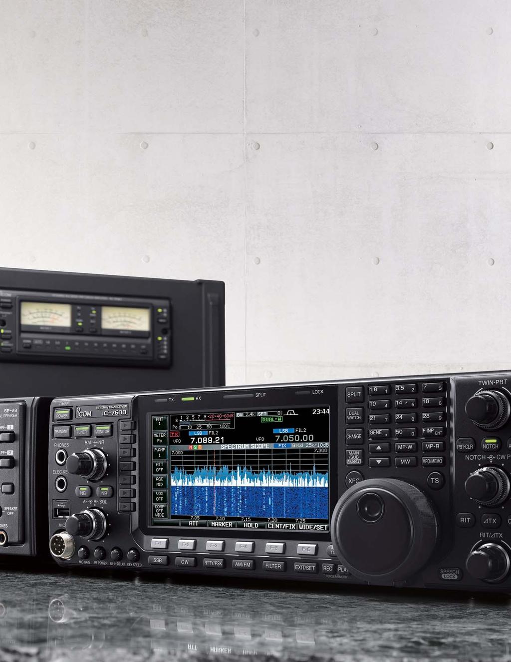
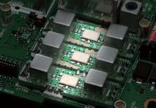
2 D isplay Pushing performance to the pinnacle The latest DSP technologies developed for the flagship models plus many decades of analog circuit expertise give the the performance advantage. The flagship s lineage: dual DSP units, 3kHz 1st (roofing) filter, double-conversion superheterodyne, all direct descendents of the flagship models. D u al DSP R eceiver Separate DSP units for transmitter/ receiver and spectrum scope. 1 st IF Filter Three built-in 1st IF (roofing) filters: 3, 6 and 15kHz. HF/50MHz TRANSCEIVER 5.8-inch WQVGA ( pixel) ultra-wide viewing angle TFT display with long-life LED backlighting. W aterfall Spectru m Scope High-resolution real-time spectrum scope with waterfall function using a dedicated DSP unit. U SB System Easily connect keyboards, mouse, flash memory drives, and PCs. P SK The double-conversion superheterodyne system and the image rejection mixer improve inband IMD. Con nectors Operation Built-in PSK and RTTY operation with a USB keyboard - PC not required.


3


 (Vertical) Backlighting Type LED (White) CCFL (Cold cathode fluorescent lamp) *These specifications show the specifications of the individual devices only.")


4 Versatile Functions and Intuitive Operation The real performance of the is apparent in the front lines of a DX contest. 5.8 inch ultra-wide viewing angle TFT display Digital voice memory Programmable band edge beep Microphone equalizer and adjustable transmit bandwidth The 's ultra-wide viewing angle display has excellent color rendition and high contrast ratio with fast response time. These features allow the spectrum scope and simulated analog meters to move smoothly and naturally. White LED backlighting offers faster start-up, stable brightness, and very long life. Ultra-wide viewing angle display Photo taken with room light turned off. LCD and backlight Comparison between and IC-756PROIII* IC -756PROIII Size 5.8 inch WQVGA 5 inch QVGA LCD Viewing Angle 180 (approx.) (Horizontal/Vertical) 90 (approx.) (Horizontal) 60 (approx.) (Vertical) Backlighting Type LED (White) CCFL (Cold cathode fluorescent lamp) *These specifications show the specifications of the individual devices only. With digital voice memory, you can record the incoming signal and immediately replay the audio, a must-have feature for DXing and contesting. Because the transceiver is recording continuously, time-shift playback can replay the 15 seconds of audio that you heard <before> you pushed the Rec button! The has a 4 channel transmit memory (maximum 90 seconds per channel) and 20 channel receive memory (maximum 30 seconds per channel, total 200 seconds with 20 channels). In addition, the recorded incoming signal can be saved on a USB flash drive. Multi-function meter Digital Voice Recorder Voice memory buttons You can program the band edge not only according to the amateur radio band plan but also more specific frequencies like contest frequencies, CW operating mode, etc. If you try to operate on the OFF band, the transceiver alerts you with a beep sound. You can also inhibit transmitting in the OFF band. Built-in memory keyer Built-in memory keyer provides 4 channels for CW mode and 8 channels each for RTTY and PSK31 modes, capable of storing up to 70 characters for each channel. The memory keyer is useful for sending CQ or exchanging numbers during contests. When not contesting, you can store and send your name, QTH, rig, etc. With a USB keyboard, you can send memory contents using a function key on the keyboard. Memory keyer screen Optional IP remote control software The built-in audio equalizer has separate bass and treble adjustments for a total of 121 combinations, so you can adjust the tonal quality of your voice as you want. In addition, the transmit bandwidth is selectable from 100, 200, 300, 500Hz at the low-pass edge, and 2500, 2700, 2800, 2900Hz at the high-pass edge, respectively. Three types of high and low combinations can be stored in the memory as favorite settings. With this flexibility of DSP-based waveform shaping, transmit audio quality is adjustable to your preference. High power final amplifiers High-power FET transistors, RD100HHF1, are used in the PA unit providing excellent signal quality and low IMD characteristics. With a large heat sink and cooling fans, reliable 100W output at high duty cycle can be used, for example in contesting or data modes. High power FET Transistors Two types of send relay settings Spectrum waterfall display The dedicated spectrum scope DSP with built-in digital filtering greatly improves dynamic range, response time, and frequency accuracy of the spectrum scope. The scope automatically selects the optimum resolution based on the sweep bandwidth. The waterfall display captures signal strengths over time. This allows you to see signals that may not be apparent on a normal scope. You can monitor band conditions between the selected sweep edges (Max. 500kHz) in the fixed mode, as well as sweep a selected band width centered on the receiving frequency in the center mode. Mouse operation Spectrum scope with waterfall (wide screen setting) Connect a USB mouse to select various spectrum scope features. can work with mouse operation, you You can point and clcik the mouse for Click-and-Listen receiver control. * A USB hub is required to simulataneously connect both a USB mouse and keyboard. Installation example of a USB mouse For example: Left-click to select a signal or operating frequency Right-click to temporarily select a different frequency. Release the mouse button to return to the original frequency. Click a button (either left or right) and move to the right or left to increase or decrease the operating frequency (similar to rotating the main dial) The multi-function meter allows you to observe the transmit/receive conditions at a glance. In addition to the signal strength, transmit power level, ALC, compression level and SWR meters, the shows the drain terminal voltage of the final amplifier (Vd), the drain current of the final amplifier (Id) and temperature of the PA circuit (TEMP). RF speech compressor The digital RF compressor boosts average RF output power, improving signal strength and readability. RTTY/PSK31 operation with a USB keyboard Simply plug in a USB keyboard to operate RTTY and PSK! The digital twinpeak filter greatly reduces interference and a tuning indicator helps you zerobeat the signals. Eight RTTY and PSK transmit memories store up to 62 characters per channel. Triple band stacking register Multi-function meter setting screen The triple band stacking register quickly memorizes and calls up the operating frequency and mode for 3 channels on each band. Just push the band key button (ten-key pad), and you can call up the last operating frequency and mode. This function is convenient especially when switching bands during contests, etc. The optional software allows you to operate the from a remote PC over the Internet or local home network. The gives consitent response time as the main dial tunes smoothly. In addition, the optional RC-28 remote encoder provides a hardware dial/transmit function for realistic dial operation. IP Remote Control through your Home Network RC-28 Other outstanding features [Antenna connectors] Two Tx/Rx antenna connectors with automatic antenna selector Rx antenna In/Out connector for receiver antenna or external attenuator [Receiver] General coverage receiver* covers from 30kHz to 60MHz (* Some frequency bands are not guaranteed, depending on version) Two types of receiver preamplifiers : Preamp 1: Increases low level signal improving intermodulation characteristics Preamp 2: High gain preamplifier Built-in 3-step RF attenuator (6, 12 and 18dB) [Transmitter] Tx monitor 50 CTCSS tone encoder and decoder VOX capability (Voice operated transmission) All mode power control [CW mode] DSP controlled CW keying waveform shaping Multi-function electronic keyer with adjustable keying speed, dot-dash ratio, paddle polarity and bug keyer CW pitch control from 300Hz to 900Hz Double key jack Full break-in function and semi break-in function Adjustable CW envelope Audio peak filter AF level setting Rear panel view Ground Terminal Antenna Connectors DC Power Socket Transverter Jack Receive Antenna Connectors IP Remote Control over the Internet RC-28 Remote location ALC Input Jack SEND Control Jack Tuner Control Socket Accessory Sockets Key Jack Transceiver location Internet IP Network Meter Jack USB Connector CI-V Remote Control Jack External Speaker Jack For amplifier keying (SEND jack), you can select either a mechanical relay (max. 16V/500mA) or a FET switch (max. 250V/200mA). The FET switch is designed to key older tube-type amplifiers that may have high voltage on the SEND line. In addition, TX delay function sets the transmission timing for use with an external amplifier which has a slow TX rise time. Built-in high-speed automatic antenna tuner The antenna tuner memorizes its settings based on your transmit frequency, so that it can rapidly tune when you change bands. High-voltage capacitors allow continuous-duty-cycle full-power operation. [Operation] Digital meter indicates output power, ALC level, SWR, COMP (compression level), Id (drain current of the final amplifier) and Vd (voltage of the final amplifier) Built-in voice synthesizer announces the frequency, mode and S-meter level in English Memory pad stores up to 10 operating frequencies Quick split function and frequency lock function Single knob control from RF gain to squelch RIT and TX variable up to ±9.999kHz Two clocks to show local and UTC time 1Hz pitch tuning and indication 101 memories with 10-character name Program, memory, select memory and f scans Auto tuning step function Adjustable tuning dial tension Dial lock Band edge beep (Can be disabled) AH-4 control circuit Automatic tuning speed for data mode operation Screen saver function Added RIT, TX, antenna control and logging software commands for CI-V remote control Wake-up function from the standby mode via the remote jack (CI-V)

 Frequency resolution 1Hz (minimum) Current drain TX: 23A (Max. power) RX: 3.5A/3A (Max. audio/standby) 340 116 279.3 mm; 13.39 4.")


 (BW=2.")
 CW (BW=500Hz, sharp) RTTY (BW=350Hz) AM (BW=6kHz) FM (BW=15kHz) Spurious and image rejection ratio Audio output power RIT variable range Matching impedance range Minimum operating power")
 0.3μV SSB, CW, RTTY, PSK: Less than 3.2μV (Pre-amp: ON) FM: Less than 0.3μV (Pre-amp: ON) More than 2.4kHz/ 6dB 500Hz/ 6dB 350Hz/ 6dB 6.0kHz/ 6dB 12.")
5 HF/50MHz TRANSCEIVER SPECIFICATIONS GENERAL Frequency coverage* 1 (Unit: MHz) Receiver * 2 Transmit * 1 Showing USA version. Varies according to version. * 2 Some frequency bands are not guaranteed. SSB, CW Mode USB, LSB, CW, RTTY, PSK31, AM, FM No. of memory channels 101 (99 regular, 2 scan edges) Antenna connector SO and RCA 1 (50Ω unbalanced (Tuner off)) Operating temp. range 0 C to +50 C; +32 F to +122 F Power supply requirement 13.8V DC ±15% Frequency stability Less than ±0.5ppm (0 C to +50 C) Frequency resolution 1Hz (minimum) Current drain TX: 23A (Max. power) RX: 3.5A/3A (Max. audio/standby) mm; in Dimensions (W H D, projections not included) Weight (approximate) Output power Modulation system Spurious emissions Carrier suppression Unwanted sideband suppression Microphone impedance * kg; 22 lb TRANSMITTER SSB/CW/FM/RTTY/PSK31: 2 100W AM: 1 30W SSB : Digital P.S.N. modulation AM : Digital low power modulation FM : Digital phase modulation HF bands: More than 50dB 50MHz band: More than 63dB More than 40dB More than 55dB 600Ω (8-pin connector) All stated specifications are subject to change without notice or obligation Receive system Intermediate frequencies Sensitivity (typical) (BW=2.4kHz, at 10dB S/N) AM (BW=6kHz, at 10dB S/N) FM (BW=15kHz, at 12dB SINAD) Squelch sensitivity (threshold) Selectivity SSB (BW=2.4kHz, sharp) CW (BW=500Hz, sharp) RTTY (BW=350Hz) AM (BW=6kHz) FM (BW=15kHz) Spurious and image rejection ratio Audio output power RIT variable range Matching impedance range Minimum operating power Tuning accuracy Insertion loss RECEIVER Double conversion super-heterodyne system MHz/36kHz (1st/2nd) (HF: Pre-amp 1 ON, 50MHz: Pre-amp 2 ON) MHz MHz 50 54MHz 0.15μV 0.12μV 6.3μV 2.0μV 1.6μV 0.5μV ( MHz) 0.3μV SSB, CW, RTTY, PSK: Less than 3.2μV (Pre-amp: ON) FM: Less than 0.3μV (Pre-amp: ON) More than 2.4kHz/ 6dB 500Hz/ 6dB 350Hz/ 6dB 6.0kHz/ 6dB 12.0kHz/ 6dB More than 70dB Less than 3.8kHz/ 60dB 900Hz/ 60dB 650Hz/ 60dB 15.0kHz/ 60dB 20.0kHz/ 60dB More than 2.0W (10% distortion, 8Ω load) ±9.999kHz ANTENNA TUNER HF bands: 16.7Ω to 150Ω unbalanced (VSWR better than 3:1) 50MHz: 20Ω to 125Ω unbalanced (VSWR better than 2.5:1) HF bands: 8W 50MHz band: 15W VSWR 1.5:1 or less (Motor stopped) Less than 1.0 db (after tuning at 100W output) Supplied accessories: Hand microphone, HM-36 Carrying handle, MB-121 DC power cable Spare fuses CW key plugs OPTIONS HM-36 HAND MICROPHONE Some options may not be available in some countries. Please ask your dealer for details. DESKTOP MICROPHONES SM-50 SM-30 SP-23 EXTERNAL SPEAKER PS-126 DC POWER SUPPLY AH-4 HF+50MHz AUTO- MATIC ANTENNA TUNER AH-2b ANTENNA ELEMENT Dynamic microphone with low-cut filter Compact, lightweight electret microphone. Hi-pass and low-pass filters with two cut-off frequecies. 13.8V DC, 25A max. Covers MHz with a 7m (23ft) or longer wire antenna. Covers 7 54MHz. Use with AH-4. IC-PW1 HF+50MHz 1kW HF LINEAR AMPLIFIER CT-17 CI-V LEVEL CONVERTER IP REMOTE CONTROL SOFTWARE RC-28 USB REMOTE ENCODER AH-5NV NVIS KIT OPC-2321 CONTROL CABLE AH-740 AUTOMATIC TUNING ANTENNA For use with Fiberglass mobile mounting antenna element for use with AH-740. Covers MHz (amateur band) with AH-740. Control cable for use with AH-740. (6m; 19.6ft) Covers MHz (amateur band). OPC-2321 is required. The LCD display may have cosmetic imperfections that appear as tiny spots. This is not a malfunction or defect, but a normal characteristic of LCD displays. Icom, Icom Inc. and Icom logo are registered trademarks of Icom Incorporated (Japan) in Japan, the United States, the United Kingdom, Germany, France, Spain, Russia, Australia, New Zealand and/or other countries. 09GS002E Icom Inc.
Pushing performance to the pinnacle
 Pushing performance to the pinnacle The latest DSP technologies developed for the IC-7800/7700 plus over 45 years of analog circuit expertise give the IC-7600 the performance advantage. The flagship's
The amazing evolution of the 706 series
 The amazing evolution of the 706 series The IC-706MKIIG carries on the 706 series tradition of base station performance and features in a mobile reg-sized package. Building on this legacy, frequency coverage
SPECS FEATURES SUPPLIED ACCESSORIES. HF All Band Transceiver
 718 HF All Band Transceiver RX 0.030-29.999999MHz* TX 1.800-1.999999 MHz** 3.500-3.999999 MHz** 7.000-7.300000 MHz 10.100-10.150000 MHz 14.000-14.350000 MHz 18.068-18.168000 MHz 21.000-21.450000 MHz 24.890-24.990000
Icom IC-9100 HF/VHF/UHF transceiver
 263 Walsall Road, Great Wyrley, Walsall, WS6 6DL Established 1997. Open Monday - Friday 9am - 5pm and Saturday 9.30am - 4pm Tel: 01922 414 796 Fax: 01922 417829 Skype: radioworld_uk Icom IC-9100 HF/VHF/UHF
December A top of the line transceiver with ultimate receiver performance
 December 2007 HF/50MHz TRANSCEIVER i7700 A top of the line transceiver with ultimate receiver performance To claim the right of being a top of the line transceiver, it is necessary to have the absolute
IC-F7000. Advanced selective call and ALE make HF communication easier than ever!
 Page 1 of 5 HF TRANSCEIVER IC-F7000 Advanced selective call and ALE make HF communication easier than ever! The IC-F7000 is an HF land mobile transceiver especially designed forlong distance communications.
i7610 Technical Report Volume 1
 i7610 Technical Report Volume 1 ~ Profile ~ Outstanding HF Experience Right Here Icom s mid class HF transceivers evolved especially with the IC-756, IC- 756PRO and IC-7600, and were technology leaders
i7610 Technical Report Volume 1
 i7610 Technical Report Volume 1 ~ Profile ~ Outstanding HF Experience Right Here Icom s mid class HF transceivers evolved especially with the IC-756, IC756PRO and IC-7600, and were technology leaders in
ICOM IC-R8600 Specifications, Features & Options
 General Frequency coverage IC-R8600 USA: 0.010000 821.999999MHz*, 851.000000 866.999999MHz, 896.000000 3000.000000MHz (*Guaranteed range: 0.100000 821.999999MHz) Antenna connector Frequency stability Mode
RF Direct Sampling Takes You to the Next Level
 HF/50MHz TRANSCEIVER RF Direct Sampling Takes You to the Next Level Outstanding HF Experience Right Here RF Direct Sampling Takes You to the Next Level with Advanced RMDR and True Dual Receive Whether
Four 32-bit floating point DSP units +40dBm ultra high intercept point
 Icom has been the world pioneer in amateur radio for 40 years. The first to bring transistor technology, digital PLL technology and the latest DSP technology to name a few achievements. It is therefore
TS-590SG HF/ 50MHz All-Mode TRANSCEIVER_
 New Product Release Information Oct 2014 TS-590SG HF/ 50MHz All-Mode TRANSCEIVER_ Kenwood introduces Updated to new G version new HF/50MHz All-Mode Transceiver Four years ago we launched our best-selling
i2820h (USA) ie2820(europe)
 ie2820(europe)") January 2007 DUAL BAND TRANSCEIVERS i2820h (USA) ie2820(europe) The above photo shows the IC-2820H. The IC-E2820 differs slightly from this photo. Icom proudly announces the debut of the new dual band
January 2007 DUAL BAND TRANSCEIVERS i2820h (USA) ie2820(europe) The above photo shows the IC-2820H. The IC-E2820 differs slightly from this photo. Icom proudly announces the debut of the new dual band
LnR Precision, Inc. 107 East Central Avenue, Asheboro, NC
 LD5 CW/SSB QRP Transceiver Quick guide manual Description: At the development base of the digital signal processing unit, an algorithm is embedded for IQ processing of the channels with phase suppression
From 40 years of RF design expertise comes the Masterpiece Ham Radio Transceiver
 From 40 years of RF design expertise comes the Masterpiece Ham Radio Transceiver Icom is a pioneer in the amateur radio world. Starting with the first analog PLL circuit in the IC-200 to the ground-breaking
Second Hand Yaesu FTDX5000MP HF base station transceiver
 263 Walsall Road, Great Wyrley, Walsall, WS6 6DL Established 1997. Open Monday - Friday 9am - 5pm and Saturday 9.30am - 4pm Tel: 01922 414 796 Fax: 01922 417829 Skype: radioworld_uk Second Hand Yaesu FTDX5000MP
LD5 CW/SSB QRP Transceiver SDR /DSP
 LD5 CW/SSB QRP Transceiver SDR /DSP Quick guide manual Description: At the development base of the digital signal processing unit, an algorithm is embedded for IQ processing of the channels with phase
INSTALLATION AND CONNECTIONS Section 2
 STLLTION ND CONNECTIONS Section Unpacking - ntenna jumper cable connection - Selecting a location - Rack mounting handle attachment - Grounding -3 ntenna connection -3 CF (Compact Flash) memory card -3
The Icom IC Adam Farson VA7OJ. A New Top-class HF/6m Transceiver. IC-7700 Information & Links
 The Icom IC-7700 A New Top-class HF/6m Transceiver Adam Farson VA7OJ IC-7700 Information & Links Copyright 2008 North Shore Amateur Radio Club NSARC HF Operators IC-7700 1 IC-7700 front panel This is a
GRAND STRAND AMATEUR RADIO CLUB
 The GRAND STRAND AMATEUR RADIO CLUB (GSARC) Myrtle Beach SC is offering used amateur related equipment for sale. Written bids may be submitted to the GSARC up to Friday, November 23 rd, 2018. Only currently
RF Direct Sampling Takes You to the Next Level
 HF/50MHz TRANSCEIVER RF Direct Sampling Takes You to the Next Level Outstanding HF Experience Right Here RF Direct Sampling Takes You to the Next Level with Advanced RMDR and True Dual Receive Whether
Icom IC-7851 HF & 50MHz transceiver
 Icom IC-7851 HF & 50MHz transceiver A new flagship is born: the current market leader in terms of performance 36 PHOTO 1: IC-7851 front view. INTRODUCTION. In 2004, Icom launched their IC-7800 top-of-the-range
From 40 years of RF design expertise comes the Masterpiece Ham Radio Transceiver
 From 40 years of RF design expertise comes the Masterpiece Ham Radio Transceiver Icom is a pioneer in the amateur radio world. Starting with the first analog PLL circuit in the IC-200 to the ground-breaking
Technician License Course Chapter 5. Lesson Plan Module 11 Transmitters, Receivers and Transceivers
 Technician License Course Chapter 5 Lesson Plan Module 11 Transmitters, Receivers and Transceivers Generalized Transceiver Categories Mobile Single Band Dual Band All Band Multimode Handheld (HT) VHF/UHF
About the HDSDR software operations for the IC-R8600
 About the HDSDR software operations for the IC-R8600 These instructions describe how to use the HDSDR software. Before reading this guide, please read How to use the IC-R8600 as an SDR receiver that can
SPECIFICATIONS GENERAL RECEIVER
 HF/50MHz TRANSCEIVER Whether it is poor band conditions, or battling to pick out a call in a large pile-up, faint signals have always been a challenge for DXers and Contesters around the world. The difference
RF Direct Sampling Takes You to the Next Level
 HF/50MHz TRANSCEIVER RF Direct Sampling Takes You to the Next Level Outstanding HF Experience Right Here RF Direct Sampling Takes You to the Next Level with Advanced RMDR and True Dual Receive Whether
QUICK REFERENCE GUIDE
 QUICK REFERENCE GUIDE Installation 1. Install a ground system for DC noise suppression and RFI suppression 2. Install your DC power supply 3. Install lightning protection. This will help protect more than
DX AM FM SSB CW PA Amateur Base Station Transceiver OWNER S MANUAL RX / TX 2 4 POWER NF CHANNEL MODE RF POWER OFF CAL OFF OFF CALIBRATE
 1 2 3 6 4050 ULA 6070 TI 80 90 100 9 DX 2517 2517 RX / TX 0 2 4 SWR WATTS SET 81012 22 1 010 3 2030 5 MOD 7 ON dbover 9 SIGNAL +20 +40+60 PA FM AM USB LSB CW POWER ON SWR NB / ANL R.BEEP +10KHz NF CHANNEL
User Manual. Specifications...3. Control and Operation Microphone...8. Installation...9. Installation of Main Unit...9
 Contents Specifications...3 Control and Operation...4-7 Microphone...8 Installation...9 Installation of Main Unit...9 Antenna Installation...9 Operational test...9 Frequency Bands Table...10 Frequency
RF Direct Sampling Takes You to the Next Level
 HF/50MHz TRANSCEIVER RF Direct Sampling Takes You to the Next Level Outstanding HF Experience Right Here RF Direct Sampling Takes You to the Next Level with Advanced RMDR and True Dual Receive Whether
2012 Edition HAM RADIO PRODUCTS. All Band Transceivers. Mobile Transceivers. Handheld Transceivers. Base Station Transceivers
 2012 Edition HAM RADIO PRODUCTS All Band Transceivers Mobile Transceivers Handheld Transceivers Base Station Transceivers Icom s flagship HF transceiver +40dBm 3rd order intercept point (in the HF bands)
Using measurement methods described in Australian/New Zealand Standard AS/NZS 4770:2000
 Barrett 2050 HF transceiver Using measurement methods described in Australian/New Zealand Standard AS/NZS 4770:2000 General Specifications Equipment Standards Transmit frequency range Receive frequency
18-CHANNEL MOBILE CB TRANSCEIVER MODEL CB-845
 18-CHANNEL MOBILE CB TRANSCEIVER MODEL CB-845 INSTRUCTION HANDBOOK RAll JEFFERSOn CITIZEN BAND RADIO MESSAGE TO THE OWNER CONGRATULATIONS! As the new owner of Ray Jefferson Model CB-845 CB Mobile Transceiver,
From 40 years of RF design expertise comes the Masterpiece Ham Radio Transceiver
 From 40 years of RF design expertise comes the Masterpiece Ham Radio Transceiver Icom is a pioneer in the amateur radio world. Starting with the first analog PLL circuit in the IC-200 to the ground-breaking
HR MHZ AM-FM AMATEUR RADIO HF TRANSCEIVER OWNER'S MANUAL. Content of the packaging
 HR-2800 28 MHZ AM-FM AMATEUR RADIO HF TRANSCEIVER OWNER'S MANUAL NOTICE! It is recommended to carefully read this owner s manual before using the product. This will also help to prevent illegal use of
INSTALLATION AND CONNECTIONS
 INSTALLATION AND CONNECTIONS 3 Unpacking After unpacking, immediately report any damage to the delivering carrier or dealer. Keep the shipping cartons. For a description and a diagram of accessory equipment
Barrett 950 HF transceiver specifications Using measurement methods described in European Telecommunication Standard
 Barrett 950 HF transceiver specifications Using measurement methods described in European Telecommunication Standard 300 373. General Specifications Equipment Standards Transmit frequency range Receive
LBI-31564A. Mobile Communications. DELTA - SX MHz RADIO COMBINATIONS (NEGATIVE GROUND ONLY) Maintenance Manual
 Maintenance Manual") A Mobile Communications DELTA - SX 136-174 MHz RADIO COMBINATIONS (NEGATIVE GROUND ONLY) Maintenance Manual TABLE OF CONTENTS MILITARY AND SYSTEM SPECIFICATIONS................................. 2-3 COMBINATION
A Mobile Communications DELTA - SX 136-174 MHz RADIO COMBINATIONS (NEGATIVE GROUND ONLY) Maintenance Manual TABLE OF CONTENTS MILITARY AND SYSTEM SPECIFICATIONS................................. 2-3 COMBINATION
SUBELEMENT T4. Amateur radio practices and station set up. 2 Exam Questions - 2 Groups
 SUBELEMENT T4 Amateur radio practices and station set up 2 Exam Questions - 2 Groups 1 T4A Station setup: connecting microphones; reducing unwanted emissions; power source; connecting a computer; RF grounding;
KWM-2/2A Transceiver THE COLLINS KWM-2/2A TRANSCEIVER
 KWM-2/2A Transceiver Click the photo to see a larger photo Click "Back" button on browser to return Courtesy of Norm - WA3KEY THE COLLINS KWM-2/2A TRANSCEIVER Unmatched for versatility, dependability and
Elmer Session Hand Out for 3/3/11 de W6WTI. Some Common Controls Found On Amateur Radio Transceivers. (From ARRL web site tutorial)
") Elmer Session Hand Out for 3/3/11 de W6WTI Some Common Controls Found On Amateur Radio Transceivers. (From ARRL web site tutorial) The placement of the controls may vary from manufacturer to manufacturer
Elmer Session Hand Out for 3/3/11 de W6WTI Some Common Controls Found On Amateur Radio Transceivers. (From ARRL web site tutorial) The placement of the controls may vary from manufacturer to manufacturer
CON NEX HP. OWNER'S MANUAL Full Channel AM/FM Amateur Mobile Transceiver TABLE OF CONTENTS TUNING THE ANTENNA FOR OPTIMUM S.W.R..
 TABLE OF CONTENTS PAGE SPECIFICATIONS... 2 INSTALLATION... 3 LOCATION... 3 CON NEX - 4300HP MOUNTING THE RADIO... 3 IGNITION NOISE INTERFERENCE... 4 ANTENNA... 4 TUNING THE ANTENNA FOR OPTIMUM S.W.R..
THE TRANSCEIVER Instruction Manual
 THE TRANSCEIVER i7800 Instruction Manual A-6328H-1EX-q Printed in Japan 2004 Icom Inc. FOREWORD Congratulations! You are the owner of the world s most advanced amateur HF/50 MHz transceiver IC-7800. The
Frequency Coverage MHz RF Power Output 30W SSB / 9W AM/ 30W FM Dual Finals on Heat Sink Modes AM, FM, USB, LSB Microprocessor
 MAGNUM M-257 30W AM/ /FM/SSB 10--11 Meterr Mobile Trranscei ivverr n Prri iiccee: : US$ 250..00 eexx ssttoocckk JJaakkaarrttaa (Arrrri ( iivvi iinngg 2 d weeeekk iinn i Maarrcchh) ) SPECIFICATIONS Frequency
Midland 248XL I NSTRUCTION GUI DE
 Midland 248XL I NSTRUCTION GUI DE INDEX Introduction...2 Function and location of the controls...3 Installation...7 Power supply...7 Installing an antenna...7 How to use your Midland 248XL...8 Frequency
FT-897 Alignment. Local Oscillator Adjustment. PLL Adjustment
 FT-897 Local Oscillator Adjustment Reference Frequency Adjustment a. Connect a frequency counter to TP1032. b. Adjust the trimmer capacitor (TC5001) for 67.875000MHz ±5Hz on the frequency counter. c. Connect
All Things icom Microphone Basics
 All Things icom Microphone Basics 22 June 2016 - Reprinted with permission from the Heil. http://www.heilsound.com/amateur/support/dsp-settings/all-things-icom Important! The icom 7300 has been updated
OPERATING GUIDE VHF TRANSCEIVER. Iç-G88
 OPERATING GUIDE VHF TRANSCEIVER Iç-G88 INTRODUCTION PREFACE We appreciate you choosing Icom for your communication needs. The MDC 1200 signaling system is built into your IC-G88 vhf transceiver. IMPORTANT
Development of the QSX transceiver kit
 Development of the QSX transceiver kit Norfolk Amateur Radio Club Wednesday 9-Jan-2019 Hans Summers, G0UPL http://qrp-labs.com QCX 5W CW transceiver kit QRP Labs CW Xcvr Introduced at YOTA 2017 summercamp
INSTRUCTION MANUAL VHF/UHF ALL MODE TRANSCEIVER. i910h
 INSTRUCTION MANUAL VHF/UHF ALL MODE TRANSCEIVER i910h IMPORTANT EXPLICIT DEFINITIONS READ THIS INSTRUCTION MANUAL CAREFULLY before attempting to operate the transceiver. SAVE THIS INSTRUCTION MANUAL. This
Icom IC A Look Under the Hood Bruce Wampler - WA7EWC
 Icom IC-7300 A Look Under the Hood Bruce Wampler - WA7EWC The Icom IC-7300 is a brand new (April 2016), Direct Conversion, 100% SDR. It is the first SDR amateur radio transceiver by one of the major Japanese
Operation Manual. SlJPER ST AR Channel Mobile 5-Mode Transceiver -----~- --:.. KTSS200NXX ,, I
 Operation Manual!.,, SlJPER ST AR 2000 200 Channel Mobile 5-Mode Transceiver -----~- --:.. KTSS200NXX General Description l Frequency/Channel Chart The Super Star -2000 is a combination transmitter-receiver
RD988 Super Version. Intelligent Super Repeater
 RD988 Super Version Intelligent Super Repeater DMR Simulcast and DMR Trunking upgradable IP Multi-site Connection Digital telephone Interconnection RDAC Remote Management Software RD988 Super Version Intelligent
IC-756 Pro III vs. Pro II
 IC-756 Pro III vs. Pro II Improvements in the Pro III vs. the Pro II Adam Farson VA7OJ IC-756Pro3 Information & Links Copyright 2006 North Shore Amateur Radio Club NSARC HF Operators 756Pro3 vs. Pro2 1
INSTRUCTION MANUAL. HF/50 MHz ALL MODE TRANSCEIVER
 INSTRUCTION MANUAL HF/50 MHz ALL MODE TRANSCEIVER This device complies with Part 5 of the FCC rules. Operation is subject to the following two conditions: () This device may not cause harmful interference,
Operating Station Equipment
 Amateur Radio License Class Operating Station Equipment Presented by Steve Gallafent October 3, 2007 Operating Station Equipment Modulation Modulation is the process of adding information to a radio signal
RD982i-S. Intelligent Super Repeater
 DMR Simulcast and DMR Trunking upgradable IP Multi-site Connection Digital telephone Interconnection RDAC Remote Management Software Intelligent Super Repeater RD982i-S RD982i-S Intelligent Super Repeater
INSTRUCTION MANUAL. HF/50 MHz TRANSCEIVER. i7410
 INSTRUCTION MANUAL HF/0 MHz TRANSCEIVER i0 i FOREWORD Thank you for making the IC-0 your radio of choice. We hope you agree with Icom s philosophy of technology first. Many hours of research and development
i78 INSTRUCTION MANUAL HF TRANSCEIVER
 INSTRUCTION MANUAL HF TRANSCEIVER i78 This device complies with Part 15 of the FCC rules. Operation is subject to the following two conditions: (1) This device may not cause harmful interference, and (2)
: Triple PLL, lowest reference frequency 10 khz. : ± 5 khz in 10 Hz steps, synthesized.
 PETER DE CONINCK HAGENUK RX 1001MVB RECEIVER ONL4234 SERIAL N 5820-310-6162 BELGIAN SWL DRAWING N 97 8 2.164 Technical data Frequency range Frequency resolution Frequency tuning Frequency synthesizer Frequency
NOTE FTDX9000 CAT OPERATION REFERENCE BOOK FTDX9000 OPERATING MANUAL
 NTE FTD9000 CAT PERATIN REFERENCE BK FTD9000 PERATING MANUAL CAT (CMPUTER AIDED TRANSCEIVR) PERATIN VERVIEW The CAT (Computer Aided Transceiver) System in the FTD9000 provides control of frequency, VF,
MC-80 TERMINAL INTERFACES
 DATA COMMUNICATOR 144/440MHz FM Dual Bander One of the greatest pleasures of exploration is being able to communicate each new discovery. And Kenwood s Data Communicator allows you to do just that. This
OM1006 Solid State 50 MHz Power Amplifier
 Instruction Manual OM1006 Solid State 50 MHz Power Amplifier OM POWER, s. r. o. 930 30 Báč 126 SLOVAKIA E-mail: om-power@om-power.com TABLE OF CONTENTS 1. GENERAL INFORMATION 1.1. Introduction.. 4 1.2.
FTV-1000 Operating Manual
 50MHz Transverter FTV-1000 Operating Manual FTV-1000 Operating Manual VERTEX STANDARD CO., LTD. 4-8-8 Nakameguro, Meguro-Ku, Tokyo 153-8644, Japan VERTEX STANDARD US Headquarters 10900 Walker Street, Cypress,
DC Instruction Manual. Professional FM Transceiver
 DC-1074 Professional FM Transceiver Instruction Manual Use of the citizen band radio service is licensed in Australia by ACMA Radiocommunications (Citizen Band Radio Stations) Class Licence and in New
2014 Edition HAM RADIO PRODUCTS. All Band Transceivers. Mobile Transceivers. Handheld Transceivers. Base Station Transceivers
 2014 Edition HAM RADIO PRODUCTS All Band Transceivers Mobile Transceivers Handheld Transceivers Base Station Transceivers Icom s flagship HF transceiver +40dBm 3rd order intercept point (in the HF bands)
KENWOOD SKY COMMAND SYSTEM
 KENWOOD SKY COMMAND SYSTEM Operation Manual KENWOOD COMMINICATIONS CORPORATION KENWOOD COMMUNICATIONS CORPORATION This operation manual is used for the KENWOOD SKY COMMAND SYSTEM (hereinafter referred
OWNER'S MANUAL Channels All-Mode AM/FM/USB/LSB Built in Frequency Counter Mobile Transceiver with Roger Beep
 SUPER STAR 7QOODX OWNER'S MANUAL 3360 Channels All-Mode AM/FM/USB/LSB Built in Frequency Counter Mobile Transceiver with Roger Beep TABLE OF CONTENTS Page Specifications... 2 Installation Location... 4
STORING MESSAGES Note: If [MEMORY] (F5) is unavailable in the function key guide, press [MORE] (F2). An alternate key guide will appear.
![STORING MESSAGES Note: If [MEMORY] (F5) is unavailable in the function key guide, press [MORE] (F2). An alternate key guide will appear.](/thumbs/92/107920661.jpg "STORING MESSAGES Note: If [MEMORY] (F5) is unavailable in the function key guide, press [MORE] (F2). An alternate key guide will appear.") ASSISTING YOUR SMOOTH QSO 5 If letters not transmitted yet remain in the text string buffer when [F12] is pressed at step 6, "WAIT" appears on the status bar. When the entire text string is transmitted,
ASSISTING YOUR SMOOTH QSO 5 If letters not transmitted yet remain in the text string buffer when [F12] is pressed at step 6, "WAIT" appears on the status bar. When the entire text string is transmitted,
TMR6200 HF Naval Digital Transceivers
 TMR6200 HF Naval Digital Transceivers One or Two High Performance 500 W/1 kw Transceivers in a Single Cabinet 125 W High Performance Transceiver In a 4U/19-inch Chassis Outstanding RF Performance Optimized
IC-400pro - RADIOAFICION.COM
 PROCEDURES IC-400pro - 5- PREPARATION When you adjust the contents on pages 5-5 and 5-6, SOFT- WARE, the optional CS-400PRO ADJ SOFTWARE (Rev..0 or later), *OPC- JIG CABLE (modified OPC- CLONING CABLE;
Instructions for the W0NE Remote HF Rig, IC-7300
 Instructions for the W0NE Remote HF Rig, IC-7300 The ICOM IC-7300 rig at the Witoka site is installed and connected up as a RemoteHams.com Server. This system is being opened to all W0NE club members to
ARRL Laboratory Expanded Test-Result Report ICOM IC-756 Pro
 ARRL Laboratory Expanded Test-Result Report ICOM IC-756 Pro Prepared by: American Radio Relay League, Inc. Technical Department Laboratory 225 Main St. Newington, CT 6111 Telephone: (8) 594-2 Web Site:
Radio Receivers. Al Penney VO1NO
 Radio Receivers Role of the Receiver The Antenna must capture the radio wave. The desired frequency must be selected from all the EM waves captured by the antenna. The selected signal is usually very weak
Technician License Course Chapter 3 Types of Radios and Radio Circuits. Module 7
 Technician License Course Chapter 3 Types of Radios and Radio Circuits Module 7 Radio Block Diagrams Radio Circuits can be shown as functional blocks connected together. Knowing the description of common
ICOM INSTRUCTION MANUAL. Icom Inc. HF ALL BAND TRANSCEIVER GENERAL COVERAGE RECEIVER I C 735 NEIN. . ma FeTRANSCE!EP IC-715.
 Icom Inc. 0 ICOM INSTRUCTION MANUAL HF ALL BAND TRANSCEIVER GENERAL COVERAGE RECEIVER I C 735 PliONES MIC FeTRANSCE!EP IC-715 NEIN,-77111. ma. 7.1111 AM,MO WWI, SCAN, DOWN NI-C1.1 UP FOREWORD Thank you
id- 51a id- 51e (U.S.A.) (Europe) SELLING POINTS Compact Dual Bander Receives two bands simultaneously.
 (Europe) SELLING POINTS Compact Dual Bander Receives two bands simultaneously.") November 2012 VHF/UHF DUAL BAND DIGITAL TRANSCEIVERS id- 51a id- 51e (U.S.A.) (Europe) Icom proudly announces the debut of the new dual band digital transceivers, ID-51A/ID-51E. The ID-51A/E is a VHF/UHF
November 2012 VHF/UHF DUAL BAND DIGITAL TRANSCEIVERS id- 51a id- 51e (U.S.A.) (Europe) Icom proudly announces the debut of the new dual band digital transceivers, ID-51A/ID-51E. The ID-51A/E is a VHF/UHF
ID-5100 User Evaluation & Test Report
 ID-5100 User Evaluation & Test Report By Adam Farson VA7OJ/AB4OJ Iss. 1, August 13, 2014. Part I: Brief User Evaluation. Introduction: This report describes the evaluation and lab test of ID-5100 S/N 05001175.
How do I get started on rtty (or psk)?
?") How do I get started on rtty (or psk)? The data modes have become particularly popular in recent years, with RTTY and PSK31 being heard almost every evening, particularly on 20 metres. So, now is a very
How do I get started on rtty (or psk)? The data modes have become particularly popular in recent years, with RTTY and PSK31 being heard almost every evening, particularly on 20 metres. So, now is a very
SERVICE MANUAL ADDENDUM
 Mar. 2010 SERVICE MANUAL ADDENDUM CONTENTS PARTS LIST................................ 1 BOARD LAYOUTS........................... 5 VOLTAGE DIAGRAM......................... 7 Feb. 2010 SERVICE MANUAL ADDENDUM
DSA700 Series Spectrum Analyzer
 DSA700 Series Spectrum Analyzer Product Features: All-Digital IF Technology Frequency Range from 100 khz up to 1 GHz Min. -155 dbm Displayed Average Noise Level (Typ.) Min.
User Manual. ilive 2 Wireless microphone system
 User Manual ilive 2 Wireless microphone system Safety instructions When using this electronic device, basic precautions should always be taken, including the following: 1 Read all instructions before using
evolution wireless G4 ew 100 G4-ME2 ew 100 G4-ME4 Lavalier Set
 1/7 Versatile wireless systems for those who sing, speak or play instruments with up to 42 MHz tuning bandwidth in a stable UHF range and fast, simultaneous setup of up to 12 linked systems. The perfect
Radio Receivers. Al Penney VO1NO
 Radio Receivers Al Penney VO1NO Role of the Receiver The Antenna must capture the radio wave. The desired frequency must be selected from all the EM waves captured by the antenna. The selected signal is
JUMA-TRX2 DDS / Control Board description OH2NLT
 JUMA-TRX2 DDS / Control Board description OH2NLT 22.08.2007 General Key functions of the JUMA-TRX2 DDS / Control board are: - provide user interface functions with LCD display, buttons, potentiometers
GETTING THE MOST FROM YOUR HF TRANSCEIVER FRED KEMMERER, AB1OC JANUARY 10 TH, 2017
 GETTING THE MOST FROM YOUR HF TRANSCEIVER FRED KEMMERER, AB1OC JANUARY 10 TH, 2017 Topics Its mostly about the receiver Transmitter/amplifier operation tips and tricks Common operating scenarios Not to
Transceiver selection and Specs.
 Transceiver selection and Specs. Transceivers 1956-2018 From TUBES to SDR Covers 20-10 meters in 100Khz segments, 10 available, crystal needed for each. Plug in crystal holder. 100 Watts output, final
E L E C R A F T K 2 R E V I S I O N 2 F I R M W A R E
 E L E C R A F T K 2 R E V I S I O N 2 F I R M W A R E Installation and Reference Manual Rev. B, August 28, 2001 Summary of Changes... 2 Computer Control (KIO2)... 2 Transverter Bands... 2 RTTY/Data Mode
INSTRUCTION MANUAL. HF/50 MHz TRANSCEIVER. i7200
 INSTRUCTION MANUAL HF/ MHz TRANSCEIVER i IMPORTANT R E A D T H I S I N S T RU C T I O N M A N UA L CAREFULLY before attempting to operate the transceiver SAVE THIS INSTRUCTION MANUAL This manual contains
Introduction Pag. 1. Function and location of the controls Pag. 2. Installation Pag. 3. Power supply Pag. 3. Installing an antenna Pag.
 ALAN 121 INDEX Introduction Pag. 1 E N G L I S H Function and location of the controls Pag. 2 Installation Pag. 3 Power supply Pag. 3 Installing an antenna Pag. 4 How to operate with your transceiver Pag.
DSA800. No.1 RIGOL TECHNOLOGIES, INC.
 No.1 DSA800 9 khz to 1.5 GHz Frequency Range Typical -135 dbm Displayed Average Noise Level (DANL) -80 dbc/hz @10 khz offset Phase Noise Total Amplitude Uncertainty
RCI-6300F25/150. Owner's Manual. AM/FM Amateur Transceiver With Built-in Frequency Counter. Table of Contents. Downloaded from
 Table of Contents RCI-6300F25/150 AM/FM Amateur Transceiver With Built-in Frequency Counter PAGE Chapter 1 Specifications...... 2 Chapter 2 Installation...... 3 Installing the Radio... 3 Ignition Noise
VX-4100/4200SERIES. VHF/UHF Mobile Radios
 VX-4100/4200SERIES VHF/UHF Mobile Radios HIGH POWER OUTPUT (50W VHF/45W UHF) WIDE FREQUENCY SPAN 134-174 MHz (VX-4104/4204) 400-470 MHz / 450-520 MHz (VX-4107/4207) 501 CHANNELS/32 GROUPS (VX-4200 SERIES)
ie92d (U.S.A.) (EURO)
 (EURO)") November 2007 DUAL BAND TRANSCEIVERS i92ad ie92d (U.S.A.) (EURO) Icom proudly announces the debut of submersible dual band transceiver, and IC- E92D. The /E92D is upgraded from the IC-91AD/E91 series and
November 2007 DUAL BAND TRANSCEIVERS i92ad ie92d (U.S.A.) (EURO) Icom proudly announces the debut of submersible dual band transceiver, and IC- E92D. The /E92D is upgraded from the IC-91AD/E91 series and
ELECRAFT KX3 EXTENDED VFO TEMPERATURE COMPENSATION PROCEDURE Copyright 2012 Elecraft LLC Rev. A9, November 14, 2012
 ELECRAFT KX3 EXTENDED VFO TEMPERATURE COMPENSATION PROCEDURE Copyright 2012 Elecraft LLC Rev. A9, November 14, 2012 Introduction The KX3 standard VFO temperature compensation is entirely adequate for most
Yaesu FT-25R 2-Meter Handheld Transceiver
 Yaesu FT-25R 2-Meter Handheld Transceiver Reviewed by Dan Wall, W1ZFG ARRL LoTW Administration w1zfg@arrl.org The latest entry into the field of small, inexpensive handhelds is the Yaesu FT-25R. This is
ANALOG COMMUNICATION
 ANALOG COMMUNICATION TRAINING LAB Analog Communication Training Lab consists of six kits, one each for Modulation (ACL-01), Demodulation (ACL-02), Modulation (ACL-03), Demodulation (ACL-04), Noise power
Maintenance Manual. MTD SERIES 900 MHz, 10-WATT, DATA ONLY MOBILE RADIO. Mobile Communications LBI TABLE OF CONTENTS
 Mobile Communications MTD SERIES 900 MHz, 10-WATT, DATA ONLY MOBILE RADIO TABLE OF CONTENTS RF BOARD............................... LBI-38545 AUDIO BOARD............................ LBI-38546 LOGIC BOARD............................
HF TRANSCEIVER V1.0. Copyright 2014, XIEGU, Inc. All Rights Reserved
 HF TRANSCEIVER V1.0 Copyright 2014, XIEGU, Inc. All Rights Reserved Table of Contents I. Introduction equipment Second, the device description Third, the operating instructions Four, advanced menu settings