LD5 CW/SSB QRP Transceiver SDR /DSP
|
|
|
- Sheena Small
- 5 years ago
- Views:
Transcription

1 LD5 CW/SSB QRP Transceiver SDR /DSP
2 Quick guide manual Description: At the development base of the digital signal processing unit, an algorithm is embedded for IQ processing of the channels with phase suppression of the unwanted side-band channel. Unit CPU \ DSP performs the following functions: Digital signal processing Frequency synthesizer Full control of the transceiver with direct conversion / SDR / Applicaton: Due to its small dimensions and light weight this transceiver is suitable for any portable or stationary operation. This unit contains: -CPU STM32F407, -NS -24 bit ADC PCM1803, -NS -16 bit DAC CS4338 low hissing amp -HF-generator Si line LCD -Matrix of buttons -Encoder The unit has electronic CW Iambic key, SWR meter and output power wattmeter. Functions that this unit performs are separate and switchable for reception / transmission. They are displayed on the screen display as RX / TX with symbols. The LD5 is capable of firmware update via USB port. See LNR web page for instructions. How to order: LNR Website Features Emmision Modes: SSB, CW, DIGITAL 5W output power typ. Very low noise floor due to DDC input stage The unit has an electronic CW Iambic A/B keyer, SWR meter and output power wattmeter. High stability Si 570 generator Split-frequency operation PTT can be switched by connecting PTT to ground RX/TX switching: o push PTT input to ground o AF VOX Output SWR indicator Optimal output power indicator Integrated Sequencer TX 3 band EQ presets for bass, middle and treble boost
3 Block diagram Specifications General Frequency range 7000 khz 22 MHz 40, 30, 20, 17 and 15 meter operation Modes USB, LSB, CW, CW-R DATA:CAT USB jack : CW, PSK, RTTY, SSTV 3.5mm jack Power Frequency Stability 5W output in CW / SSB +/- 3 ppm (Si570 defined) typical over 0-50 deg C
4 Supply Voltage 10.5V min to 15V max 350Ma receive and 1.5 to 2 A typical in transmit Push button operation LO temp. Stability +/- 2.5 Antenna 50 ohms BNC Dual VFO Memory 100 memory storage per band Memorize frequency, mode, VFO s Built-in speaker 0.2 watts Dimensions Weight Iambic key Pitch CW Notch Filter Noise reduction Noise Blanker CW VOX CW memory keyer long X wide x tall 19.0oz / 0,54kilogram /excluding microphone/ mode A and mode B Controls CW offset. The sidetone pitch is automatically set to equal the offset Automatic Heterodyne filter for SSB from -6 to -40 db level of attenuation of the noise from 1 to 50- use minimal necessary adjusted in the range from value 4 to 12 readings depending on interference Break in delay in CW adjustable from 0.1 seconds to 5 seconds Choose Iambic Mode A or B VOICE VOX VOX Delay adjustable from 0.1 seconds to 5 seconds SSB VOX LEVEL VOX GAIN IS MOST SENSITIVE Filters Compressor SSB SSB TX MUTE Input Power Output Power Measurement 8 different filters 4 of 4 for CW/ SSB factory presets No.4 adjustable for CW/ Hz/ and SSB/ KHz VDC 3.5 8W SWR and Power in numbers or bar 0-20dB Enable= no monitor Disable= monitor Transmitter
5 supply voltage real voltage on display Two modes CW Select a hand key or a paddle Receiver Receive sensitivity 0.2uV Preamp Ant Preamp +12 db Spurious response rejection IMD3-48Db/ 5W IMD5-43dB ATT -6 db

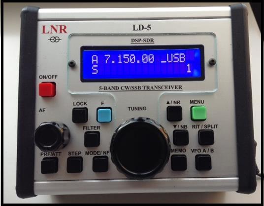
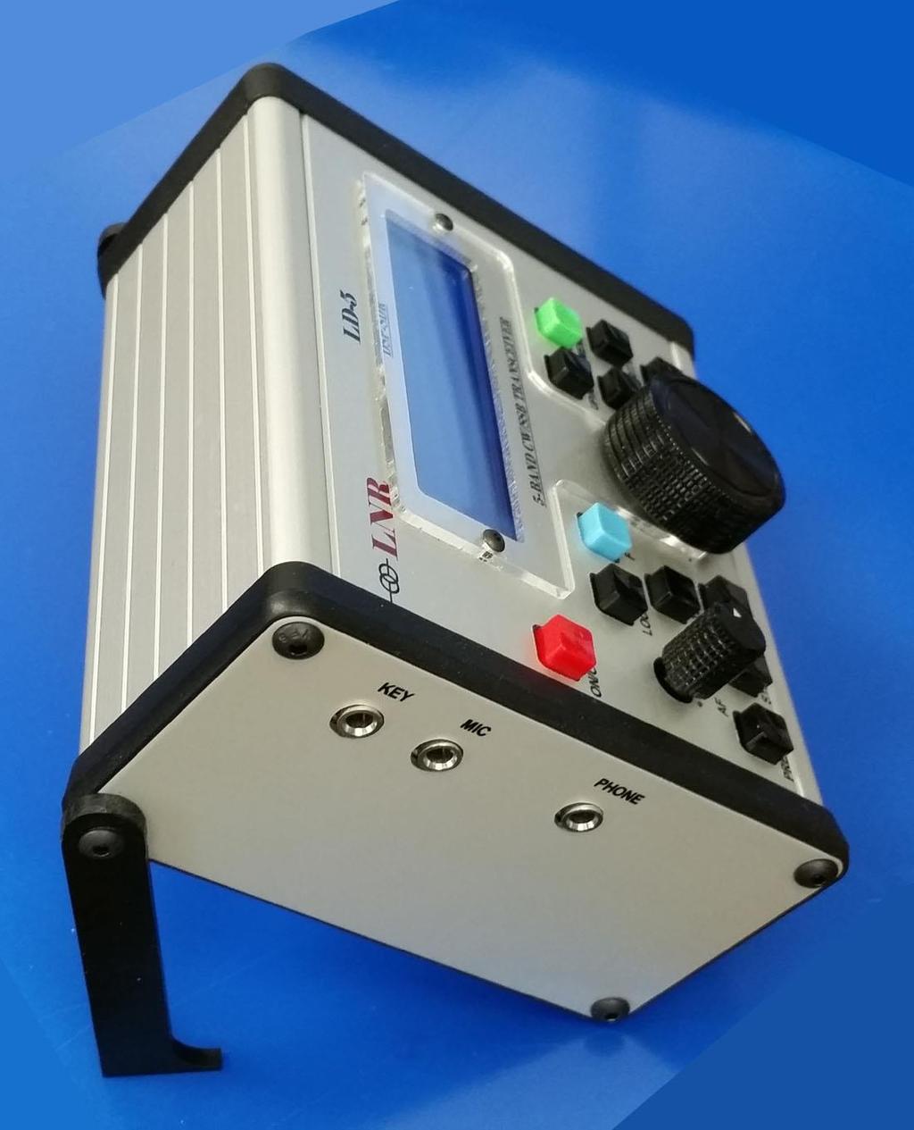
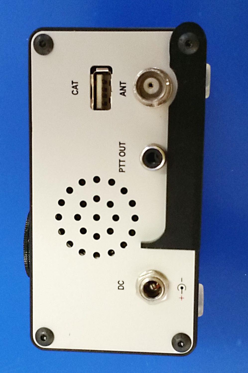
6 Front panel indicators and functions

7 DESCRIPTION of the command buttons Command ON/OFF UP Arrow DOWN Arrow MODE VFO STEP LOCK Meaning POWER ON/OFF the transceiver Change Band higher 7/10/14/18/21. In Menu mode select next menu item Change band lower. In menu mode select previous menu item. Select CW/ CWR/ LSB/ USB/DIGI Select either VFO A or B Sequential pressing of the STEP button or the Tuning encoder steps through the tuning rate. 1 bar- 1Hz 2 bars=10hz 3 bars=100hz 4 bars=1khz tuning rate. Lock/unlock the tuning dial symbol appears to the left of the mode designation on LCD
8 RIT PRE/ATT FILTER MEMO On / Off (star) after frequency =0 RIT; Shifting the frequency DOWN symbol < ; Shifting the frequency UP symbol > Memorized RIT is kept until next switch of the function off/on or power off the radio. Sequentially enables preamp ( ) approx. +16dB Preamp off= No arrow attenuator ( ) approx. -10dB Four filters are available for each mode. Filters 1-3 may be customized in the Service menu. 100 Memories for all bands with memorizing frequency, type of mode and the filter bandwidth. Memorizing : Press the MEMO button to select the memory number with TUNING, paste it from 0 to 99, then press the DOWN button again and MEMO button again frequency is stored, MODE, preamp or attenuator, Notch Filter, Noise Blanker, Noise reduction. Memory Recall: Press to select MEMO and with TUNING choose the memory you require from 0 to 99 as the display will show the preset frequency on the bottom line, then press the UP button and it will display the selected frequency and then push memory button again MEMO and then you go to: preset frequency, MODE, preamp or attenuator, Notch Filter, Noise Blanker, Noise reduction MENU Settings Enter MENU MODE by pressing MENU button and exit the menu mode by pressing the MENU again after set up. Most of the functions, related to receiving or transmitting, can be changed by values and monitored via monitor in real time. MENU AGC PITCH CW CW SPEED WEIGHT CW KEY CW VOX REVERSE CW KEY CW KEY TYPE IAMBIC MODE NOTCH FILTER Default menu settings AGC speed from is the slowest and 20 the fastest Sidetone and CW offset pitch. Changes take effect when you exit Menu mode 5 to 60 WPM. Speed change takes effect when you exit Menu mode. Adjusts the ratio of dash length to dot length: 2> 1; 2.5> 1; 3> 1; 3.5> 1; 4> 1; 4.5> 1 3:1 is standard Controls break in delay. Steps in 100mSec from 100mSec to 5 seconds Change which side of the paddle is dot and which side is dash. Two options: SIMPLE= hand key. AUTO= Paddle. Allows user to switch from Iambic mode A to Iambic mode B Adjusts notch depth from -6 db to -40dB Changes can be observed while in Menu mode.
9 NOISE BLANKER NOISE REDUCTION S-METER MODE TX METER SHOW TX POWER TX LED MODE SSB TX MUTE Adjustable using tuning knob from 4 to is maximum blanking, 12 is minimum. Changes can be heard while in Menu mode. Menu range from 1 to 100 with 1 being the least. If NR is activated from the front panel (F + NR) you can observe the effect within the Menu. Two modes: Bar Graph or readout in uv. Two options: Bar Graph (Scaler) or Watts (Number) Two options: Power in Watts or VSWR Adjusts power out. Settings from 10 to 100. Typically, a 10 setting is 1W and a 100 setting is 5W Two options: Forever= LCD backlight always on. Auto= backlight turns on for 3 seconds whenever a front panel switch or encoder is activated. Backlight off saves 40mA of current drain. SSB TX Monitor. Two options: Enable and Disable SSB COMPRESSOR SSB Mic compression from 1 to 100. SSB VOX VOX LEVEL TX EQ GAIN TX DIG SQUELCH adjustment of VOX delay for SSB DISABLE is off, Adjustable from 100mSec to 5 seconds in 100mSec steps Adjusts VOX gain in SSB mode. 3 options: Accentuate the Lows, Highs or Midrange. LowF /HiF/ MediumF Setting from using the VFO knob. This function controls the AF Gain in Digital mode Settings A 0 (zero) setting essentially turns squelch off.
10
11 FUNCION SETTINGS = PUSHING F + : RIT On any VFO- when you push RIT an asterisk appears as shown: When you move frequency up, an arrow will appear to the right: When you move frequency down, an arrow will appear to the left: SPLIT OPERATION SPLIT MODE- if you want to receive on and transmit on : SET frequency on VFO A and on VFO B REMEMBER, first VFO chosen is an RX frequency: PUSH RIT button, and then follow RIT MODE :
12 PUSH VFO A/B until VFO B appears, with reflecting RX frequency arrow to the left If you switch on TX, the frequency on VFO B will appear You will notice that VFO A frequency can move up/down, but VFO B is fixed on TX. If you wish to reverse the frequency, exit RIT Mode and switch to VFO B, then push RIT and then VFO A. PLEASE, look at the appearance : arrow shows to the right On TX you will see this :
 pass-cw off and does not affect the display- no indication. Direct setting in real time. On Noise reduction. Direct tuning in real time.")
13 MENU UP MODE DOWN FILTER Shows the power supply in place of S-meter / SWR / Power reception and transmission. It remains in this stage until pressed again F <MENU> On Noise Blanker. Direct tuning in real time. On Notch Filter (only SSB) pass-cw off and does not affect the display- no indication. Direct setting in real time. On Noise reduction. Direct tuning in real time. Modifying bandwidth of filter 4 separately for SSB and CW. Direct tuning in real time. Push F button, then FILTER and tune chosen bandwidth with TUNING for exit push FILTER. Direct setting in real time. SERVICE MODE It is strongly recommended to contact LNR Support before entering service mode Entry into service mode To enter into default settings switch OFF the radio and THEN power it up while F button is pressed. RADIO IS READY NOW!!!! Upon entering the service mode, reset all the settings IN DEFAULT EXCEPT RX IQ, TX IQ and fine tuning of the synthesizer. You should not go to factory settings RX IQ, TX IQ as they are set individually for your radio and precisely adjusted for values with additional specialized devices, TRANSMITTING and measuring in certain frequency. Each radio in the service menu is recorded INDIVIDUALY for serial number, factory settings RX IQ, TX IQ and is hard to adjust if you are not aware of procedure!!!!!!!!!!!
14 BASIC SETTINGS F button and then press the MENU button and moving with UP / DOWN and RIT IF DSP V PWR REF VFO MULT VFO STARTING FREQUENCY END FREQUENCY S METER RX IQ FILTER SSB FILTER CW AGC DSP SHOW S METER FILTER TX SSB FILTER TX CW Virtual gap frequency from 5006 to Hz / recommended to use a low-frequency virtual Adjustment of the displayed voltage Correcting the VFO frequency Divider VFO. For LD-5 = 4 / do not touch it, it is correct by the service menu/ Low end frequency of selected band change with tuning knob High end frequency of selected band change with tuning knob Setting S-METER for the range calibration Setting the mirror channel correcting the phase and amplitude of IQ for each band separately on RX - minimum reading has two modesfast and slow for quick setting and fine switched with STEP. Each transceiver is factory default recorded on the accompanying document Setup filters from 1 to 3 for each type of work. Changing the filter with the push button Filter Allows user to change the bandwidth of the first three CW filters. While in Service Mode, press Menu. Select Filter 1 CW and redefine the BW with the main tuning knob. Step to the next filter by pressing FILTER etc. Exit Menu mode to save. on / off AGC -SHOULD ALWAYS BE SET TO ENABLE Switches S meter Adjustment of bandwidth in the transmit mode /FROM 150 Hz to 3600Hz/ -. Changing adjustment of the upper frequency With the push button RIT/VIF adjustment of bandwidth in the transmit mode /FROM 50 Hz to 1000Hz/ - soft CW manipulation Hz. BELL SOUND LEVEL TX Adjustment of Power entries are shown from Power TX - power. First row on Display: TX ADC indications power when all bands are equal in
15 DESCRIPTION of the settings in transmit mode PWR / VTT POWER TX TX IQ TX EQ First row on Display: TX ADC indications power for each band separately. Second row on Display : Power Control for each band separately, shows power of radio on TX use forward wave of SWR meter settings are made on a 50 ohms dummy load and SWR = 1, setting indication varies around Correcting amplitude and phase balance in IQ channel in the transmit mode for each band separately For this purpose we need to have a separate receiver on the frequency and listen to the unwanted side band channel set on minimal hearing. Factory setting on all bands is : A F 0, band audio presets on transmit only: bass, middle. Treble boost DESCRIPTION of the current settings AGC SPEED ADJUSTABLE in levels of delay from 1 to 20 / Those settings are directly accessible by pressing MENU / PITCH CW NOTCH FILTER NOISE BLANKER NOISE REDUCTION S-METER MODE CW tones from 400 to 1000 Hz when crossing the transmit shift to the same tone Reject interfering tone only for SSB from -6 to -40 db Adjusted in the range from value 4 to 12 - readings depending on interference Level of attenuation of the noise from 1 to 50- use minimal necessary Shows scale bars or S-units in microvolt s LED Backlight brightness of the LCD from 0 to 250 CW SPEED Regulating the speed of the automatic key from 20 signs to maximum WEIGHT CW KEY Dot-dash ratio 2.5> 1 to 4.5> 1 in 0.5 CW VOX DELAY mode in CW milliseconds to 5000 milliseconds / 5 seconds / COMPRESS TX Compression microphone from 0 to 100% REVERSE CW KEY TX METER SHOW TX Reversing dot-dash to paddle Shows SWR or power in the transmit mode with bar graph or scale figures SWR or power to be displayed in the transmit mode POWER TX Regulation in mw from 10% to 100% LED MODE SSB MUTE Mode for backlight LCD - constant or relight by pressing any button or rotating of tuning knob on / off microphone - MONITOR mode in transmit

16 DIGITAL MODES IMPORTANT Make sure to connect the USB, Power Cord and Antenna before powering on the radio. Then Power ON the Radio. Finally, start up your software program: In order to operate digital mode or interface with computer, utilize the Line IN/OUT jack and cable. The radio has typical levels for audio signals similar to other amateur radios. The radio has a built-in ALC SWR protection - when SWR does not exceed 1:3 there is no change in output power. But at a greater SWR, the protection gradually lowers the power output, and at SWR = 10 the output power is only 1%. ================================================== ======================================
LnR Precision, Inc. 107 East Central Avenue, Asheboro, NC
 LD5 CW/SSB QRP Transceiver Quick guide manual Description: At the development base of the digital signal processing unit, an algorithm is embedded for IQ processing of the channels with phase suppression
TABLE OF CONTENTS 8 SOFTWARE MENU MODE SETTINGS SOFTWARE MENU QUICK GUIDE SERVICE MODE... 24
 1 TABLE OF CONTENTS 1. TABLE OF CONTENTS......................... 2 2. INTRODUCTION............................. 3 3. SPECIFICATIONS............................ 4 4. ACCESSORY PACKAGE.......................
Icom IC-9100 HF/VHF/UHF transceiver
 263 Walsall Road, Great Wyrley, Walsall, WS6 6DL Established 1997. Open Monday - Friday 9am - 5pm and Saturday 9.30am - 4pm Tel: 01922 414 796 Fax: 01922 417829 Skype: radioworld_uk Icom IC-9100 HF/VHF/UHF
Elmer Session Hand Out for 3/3/11 de W6WTI. Some Common Controls Found On Amateur Radio Transceivers. (From ARRL web site tutorial)
") Elmer Session Hand Out for 3/3/11 de W6WTI Some Common Controls Found On Amateur Radio Transceivers. (From ARRL web site tutorial) The placement of the controls may vary from manufacturer to manufacturer
Elmer Session Hand Out for 3/3/11 de W6WTI Some Common Controls Found On Amateur Radio Transceivers. (From ARRL web site tutorial) The placement of the controls may vary from manufacturer to manufacturer
SPECS FEATURES SUPPLIED ACCESSORIES. HF All Band Transceiver
 718 HF All Band Transceiver RX 0.030-29.999999MHz* TX 1.800-1.999999 MHz** 3.500-3.999999 MHz** 7.000-7.300000 MHz 10.100-10.150000 MHz 14.000-14.350000 MHz 18.068-18.168000 MHz 21.000-21.450000 MHz 24.890-24.990000
Pushing performance to the pinnacle
 Pushing performance to the pinnacle The latest DSP technologies developed for the IC-7800/7700 plus over 45 years of analog circuit expertise give the IC-7600 the performance advantage. The flagship's
TS-590SG HF/ 50MHz All-Mode TRANSCEIVER_
 New Product Release Information Oct 2014 TS-590SG HF/ 50MHz All-Mode TRANSCEIVER_ Kenwood introduces Updated to new G version new HF/50MHz All-Mode Transceiver Four years ago we launched our best-selling
The Icom IC Adam Farson VA7OJ. A New Top-class HF/6m Transceiver. IC-7700 Information & Links
 The Icom IC-7700 A New Top-class HF/6m Transceiver Adam Farson VA7OJ IC-7700 Information & Links Copyright 2008 North Shore Amateur Radio Club NSARC HF Operators IC-7700 1 IC-7700 front panel This is a
Technician License Course Chapter 5. Lesson Plan Module 11 Transmitters, Receivers and Transceivers
 Technician License Course Chapter 5 Lesson Plan Module 11 Transmitters, Receivers and Transceivers Generalized Transceiver Categories Mobile Single Band Dual Band All Band Multimode Handheld (HT) VHF/UHF
The amazing evolution of the 706 series
 The amazing evolution of the 706 series The IC-706MKIIG carries on the 706 series tradition of base station performance and features in a mobile reg-sized package. Building on this legacy, frequency coverage
HF TRANSCEIVER V1.0. Copyright 2014, XIEGU, Inc. All Rights Reserved
 HF TRANSCEIVER V1.0 Copyright 2014, XIEGU, Inc. All Rights Reserved Table of Contents I. Introduction equipment Second, the device description Third, the operating instructions Four, advanced menu settings
ELECRAFT KX3 EXTENDED VFO TEMPERATURE COMPENSATION PROCEDURE Copyright 2012 Elecraft LLC Rev. A9, November 14, 2012
 ELECRAFT KX3 EXTENDED VFO TEMPERATURE COMPENSATION PROCEDURE Copyright 2012 Elecraft LLC Rev. A9, November 14, 2012 Introduction The KX3 standard VFO temperature compensation is entirely adequate for most
LNR Precision Mountain Topper MTR-4B and MTR-5B REV 2.0 User Manual for use with versions with 16 x 2 display.
 LNR Precision Mountain Topper MTR-4B and MTR-5B REV 2.0 User Manual for use with versions with 16 x 2 display. Four band MTR 4B shown Overview: The Mountain Topper Rigs are designed to be a very small,
XIEGU COMMUNICATION X5105. HF+50MHz Portable HF Transceiver. Instruction Manual. Chongqing Xiegu Technology Co.,Ltd.
 XIEGU COMMUNICATION X5105 HF+50MHz Portable HF Transceiver Instruction Manual Chongqing Xiegu Technology Co.,Ltd. www.cqxiegu.com Important reminder: Before operating the equipment, please Security considerations:
ELAD FDM-DUO Dual Mode SDR Transceiver USER MANUAL
 ELAD FDM-DUO Dual Mode SDR Transceiver USER MANUAL www.eladit.com Contents Revision History... 4 1 Overview... 5 1.1 Notice... 5 1.2 Firmware versions... 5 1.3 Introduction... 5 1.3.1 Main Features...
Frequency Coverage MHz RF Power Output 30W SSB / 9W AM/ 30W FM Dual Finals on Heat Sink Modes AM, FM, USB, LSB Microprocessor
 MAGNUM M-257 30W AM/ /FM/SSB 10--11 Meterr Mobile Trranscei ivverr n Prri iiccee: : US$ 250..00 eexx ssttoocckk JJaakkaarrttaa (Arrrri ( iivvi iinngg 2 d weeeekk iinn i Maarrcchh) ) SPECIFICATIONS Frequency
HF/50MHz TRANSCEIVER
 HF/50MHz TRANSCEIVER D isplay Pushing performance to the pinnacle The latest DSP technologies developed for the flagship models plus many decades of analog circuit expertise give the the performance advantage.
Ten-Tec Orion/Orion II Users Manual Addendum Firmware Version V3
 Ten-Tec Orion/Orion II Users Manual Addendum Firmware Version V3 It is very important that you read this document in its entirety before using the V3 firmware. Some features behave differently than they
FT-897 Alignment. Local Oscillator Adjustment. PLL Adjustment
 FT-897 Local Oscillator Adjustment Reference Frequency Adjustment a. Connect a frequency counter to TP1032. b. Adjust the trimmer capacitor (TC5001) for 67.875000MHz ±5Hz on the frequency counter. c. Connect
TABLE OF CONTENTS TABLE OF CONTENTS 1
 TABLE OF CONTENTS TABLE OF CONTENTS 1 Chapter 1 YOUR NEW ORION II ORION II ANOTHER STEP FORWARD IN TEN-TEC INNOVATION 4 UNPACKING YOUR NEW ORION II 4 ABOUT THIS MANUAL 4 CONNECTING A POWER SUPPLY 5 A WORD
Youkits SK-1A 40m SSB/CW QRP Transceiver. Operating manual
 Youkits SK-1A 40m SSB/CW QRP Transceiver Operating manual Specifications Size: 88*38*124mm (not including knob, etc.) Weight: about 280g (not including battery pack) Supply voltage: 10-15VDC Current drain
X108G. Outdoor version Operating Manual
 XIEGU HF TRANSCEIVER X108G Outdoor version Operating Manual Chongqing XieGu Technology Co.,Ltd 403,4th buildings,youth DreamWorks, No.87, Langkou industrial park, Langkou community, Dalang Avenue,new district
200GTL ALIGNMENT REVISION: 1.0 BURKE MODEL: 200GTL REVISION: 1.2 DATE: 02/14/06. Total Pages: 6 pages. Page:1 print date: 9/23/09
 ALIGNMENT PROCEDURE MODEL: 200GTL REVISION: 1.2 DATE: 02/14/06 PREPARED BY: BURKE Total Pages: 6 pages Page:1 print date: 9/23/09 1 TEST CONDITION: 200GTL ALIGNMENT INSTRUCTION 1.0. TEST TEMPERTAURE: 77
KENWOOD SKY COMMAND SYSTEM
 KENWOOD SKY COMMAND SYSTEM Operation Manual KENWOOD COMMINICATIONS CORPORATION KENWOOD COMMUNICATIONS CORPORATION This operation manual is used for the KENWOOD SKY COMMAND SYSTEM (hereinafter referred
 The Mountain Topper by Steve Weber (KD1JV) (MTR) www.lnrprecision.com FULLY ASSEMBLED Manufactured by LNR Precision, Inc. A very small, very efficient three band QRP CW rig. Specifications: Three bands,
E L E C R A F T K 2 R E V I S I O N 2 F I R M W A R E
 E L E C R A F T K 2 R E V I S I O N 2 F I R M W A R E Installation and Reference Manual Rev. B, August 28, 2001 Summary of Changes... 2 Computer Control (KIO2)... 2 Transverter Bands... 2 RTTY/Data Mode
Amateur Station Control Protocol (ASCP) Ver Oct. 5, 2002
 Ver Oct. 5, 2002") Amateur Station Control Protocol (ASCP) Ver. 0.17 Oct. 5, 2002 Moe Wheatley, AE4JY Table of Contents 1. Purpose...4 2. Basic Protocol Concepts...5 3. Message Block Format...8 3.1. Detailed Description
Amateur Station Control Protocol (ASCP) Ver. 0.17 Oct. 5, 2002 Moe Wheatley, AE4JY Table of Contents 1. Purpose...4 2. Basic Protocol Concepts...5 3. Message Block Format...8 3.1. Detailed Description
Basic Transceiver tests with the 8800S
 The most important thing we build is trust ADVANCED ELECTRONIC SOLUTIONS AVIATION SERVICES COMMUNICATIONS AND CONNECTIVITY MISSION SYSTEMS Basic Transceiver tests with the 8800S Basic Interconnects Interconnect
INSTRUCTION MANUAL. HF/VHF ALL MODE TRANSCEIVER i746pro
 INSTRUCTION MANUAL HF/VHF ALL MODE TRANSCEIVER i746pro This device complies with Part 15 of the FCC rules. Operation is subject to the following two conditions: (1) This device may not cause harmful interference,
GRAND STRAND AMATEUR RADIO CLUB
 The GRAND STRAND AMATEUR RADIO CLUB (GSARC) Myrtle Beach SC is offering used amateur related equipment for sale. Written bids may be submitted to the GSARC up to Friday, November 23 rd, 2018. Only currently
SUBELEMENT T4. Amateur radio practices and station set up. 2 Exam Questions - 2 Groups
 SUBELEMENT T4 Amateur radio practices and station set up 2 Exam Questions - 2 Groups 1 T4A Station setup: connecting microphones; reducing unwanted emissions; power source; connecting a computer; RF grounding;
1. Your new Eagle 599 3
 Table of Contents 1. Your new Eagle 599 3 1.1. Unpacking Eagle 599 3 1.2. About this Manual 3 1.3. Accessory package 3 1.4. Connection to Antenna & Power Supply 4 1.5. A word about grounding 4 1.6. Philosophy
ADJUSTING YOUR HF RECEIVER
 ADJUSTING YOUR HF RECEIVER N5KIP January 31, 2017 Disclaimers What works on one model of radio might not work well on another CW (narrow bandwidth) and SSB (wider bandwidth) will require different receiver
Operator's Manual for the mchf transceiver Updated for firmware version Prepared by C. Turner, KA7OEI
 Operator's Manual for the mchf transceiver Updated for firmware version 0.0.211 Prepared by C. Turner, KA7OEI Preface: This manual is for the mchf transceiver, the original design by Chris Atanassov, M0NKA,
Operator's Manual for the mchf transceiver Updated for firmware version
 Operator's Manual for the mchf transceiver Updated for firmware version 0.0.219.26 20151028 Preface: This manual is for the mchf transceiver,a the good original color design tft display by Chris screen
ARRL Laboratory Expanded Test-Result Report ICOM IC-756 Pro
 ARRL Laboratory Expanded Test-Result Report ICOM IC-756 Pro Prepared by: American Radio Relay League, Inc. Technical Department Laboratory 225 Main St. Newington, CT 6111 Telephone: (8) 594-2 Web Site:
GETTING THE MOST FROM YOUR HF TRANSCEIVER FRED KEMMERER, AB1OC JANUARY 10 TH, 2017
 GETTING THE MOST FROM YOUR HF TRANSCEIVER FRED KEMMERER, AB1OC JANUARY 10 TH, 2017 Topics Its mostly about the receiver Transmitter/amplifier operation tips and tricks Common operating scenarios Not to
XIEGU COMMUNICATION X5105. HF+50MHz Portable HF Transceiver. Instruction Manual. Chongqing Xiegu Technology Co.,Ltd.
 XIEGU COMMUNICATION X5105 HF+50MHz Portable HF Transceiver Instruction Manual V1.0.03 Chongqing Xiegu Technology Co.,Ltd. www.cqxiegu.com Important reminder: Before operating the equipment, please Security
HF SIGNALS ΜBITX. The QRP HF General Coverage Transceiver you can build. Buy Now Circuit Description Wireup Tune Up Help and Support BITX Hacks
 Page 1 of 5 HF SIGNALS ΜBITX The QRP HF General Coverage Transceiver you can build Buy Now Circuit Description Wireup Tune Up Help and Support BITX Hacks ($109 USD) Page 2 of 5 The µbitx is a general coverage
Midland 248XL I NSTRUCTION GUI DE
 Midland 248XL I NSTRUCTION GUI DE INDEX Introduction...2 Function and location of the controls...3 Installation...7 Power supply...7 Installing an antenna...7 How to use your Midland 248XL...8 Frequency
INSTRUCTION MANUAL VHF/UHF ALL MODE TRANSCEIVER. i910h
 INSTRUCTION MANUAL VHF/UHF ALL MODE TRANSCEIVER i910h IMPORTANT EXPLICIT DEFINITIONS READ THIS INSTRUCTION MANUAL CAREFULLY before attempting to operate the transceiver. SAVE THIS INSTRUCTION MANUAL. This
Development of the QSX transceiver kit
 Development of the QSX transceiver kit Norfolk Amateur Radio Club Wednesday 9-Jan-2019 Hans Summers, G0UPL http://qrp-labs.com QCX 5W CW transceiver kit QRP Labs CW Xcvr Introduced at YOTA 2017 summercamp
ARRL Laboratory Expanded Test-Result Report ICOM IC-7800
 ARRL Laboratory Expanded Test-Result Report ICOM IC-78 Prepared by: American Radio Relay League, Inc. Technical Department Laboratory 225 Main St. Newington, CT 6111 Telephone: (86) 594-214 Internet: mtracy@arrl.org
Digital HF Receiver WJ-8723
 Developmental Specification WATKINS-JOHNSON April 1996 Digital HF Receiver WJ-8723 Description The WJ-8723 is a fully synthesized, general-purpose HF receiver that monitors RF communications from 5 khz
i746 INSTRUCTION MANUAL VHF/HF ALL MODE TRANSCEIVER
 INSTRUCTION MANUAL VHF/HF ALL MODE TRANSCEIVER i746 This device complies with Part 5 of the FCC rules. Operation is subject to the following two conditions: () This device may not cause harmful interference,
User Manual. Specifications...3. Control and Operation Microphone...8. Installation...9. Installation of Main Unit...9
 Contents Specifications...3 Control and Operation...4-7 Microphone...8 Installation...9 Installation of Main Unit...9 Antenna Installation...9 Operational test...9 Frequency Bands Table...10 Frequency
THE TRANSCEIVER Instruction Manual
 THE TRANSCEIVER i7800 Instruction Manual A-6328H-1EX-q Printed in Japan 2004 Icom Inc. FOREWORD Congratulations! You are the owner of the world s most advanced amateur HF/50 MHz transceiver IC-7800. The
hallicrafters PERFORMANCE SPECIFICATIONS MODEL: SR-2000 LATEST REVISION: 18 JAN 66 Code ident # Specification #
 hallicrafters PERFORMANCE SPECIFICATIONS MODEL: SR-2000 LATEST REVISION: 18 JAN 66 Code ident # 26916 Specification # 093-002154 I. GENERAL A. Power input 117V 50-60 cycles from a source capable of delivering
539 / Argonaut VI Users manual Release 1.03 May 7, 2013 Part #74479 Printed in USA 1
 Table of Contents 1.Your new Argonaut VI 539...3 1.1.Unpacking the Argonaut VI...3 1.2.About this Manual...3 1.3.Accessory package...3 1.4.Connection to Antenna & Power Supply...4 1.5.A word about grounding...4
IC-F7000. Advanced selective call and ALE make HF communication easier than ever!
 Page 1 of 5 HF TRANSCEIVER IC-F7000 Advanced selective call and ALE make HF communication easier than ever! The IC-F7000 is an HF land mobile transceiver especially designed forlong distance communications.
Second Hand Yaesu FTDX5000MP HF base station transceiver
 263 Walsall Road, Great Wyrley, Walsall, WS6 6DL Established 1997. Open Monday - Friday 9am - 5pm and Saturday 9.30am - 4pm Tel: 01922 414 796 Fax: 01922 417829 Skype: radioworld_uk Second Hand Yaesu FTDX5000MP
JUMA-TRX2 DDS / Control Board description OH2NLT
 JUMA-TRX2 DDS / Control Board description OH2NLT 22.08.2007 General Key functions of the JUMA-TRX2 DDS / Control board are: - provide user interface functions with LCD display, buttons, potentiometers
ICOM IC-R8600 Specifications, Features & Options
 General Frequency coverage IC-R8600 USA: 0.010000 821.999999MHz*, 851.000000 866.999999MHz, 896.000000 3000.000000MHz (*Guaranteed range: 0.100000 821.999999MHz) Antenna connector Frequency stability Mode
Operating Station Equipment
 Amateur Radio License Class Operating Station Equipment Presented by Steve Gallafent October 3, 2007 Operating Station Equipment Modulation Modulation is the process of adding information to a radio signal
HF Receivers, Part 3
 HF Receivers, Part 3 Introduction to frequency synthesis; ancillary receiver functions Adam Farson VA7OJ View an excellent tutorial on receivers Another link to receiver principles NSARC HF Operators HF
QRPver 20M Transceiver Review By Edward R. Breneiser, WA3WSJ
 QRPver 20M Transceiver Review By Edward R. Breneiser, WA3WSJ I was looking around for a door prize for the Boschveldt QRP Club MOC 2018 Event and found a unique QRP site. The website is QRPver.com and
Version Initial Production Release. Version Modified FM Mode transmit level control.
 Version 1.001 Initial Production Release. Version 1.002 Modified FM Mode transmit level control. Version 1.003 SWR Meter Wasn t Updating on perfect match MONITOR wasn t working in REMOTE mode (no audio
BAND DECODER and CONTROLLE R. Accessibility Upgrade and Operating Instructions
 ELE CRAFT KRC2 BAND DECODER and CONTROLLE R Accessibility Upgrade and Operating Instructions Revision A, March 4, 2004. Copyright 2004, Elecraft; All Rights Reserved Introduction The KRC2 Accessibility
HFTRANSCEIVER X108G. OperatingManual XIEGUTECH V1.01A. OutdoorEdition. Revise: Copyright 2015, XIEGU, Inc.
 HFTRANSCEIVER X108G OperatingManual XIEGUTECH V1.01A OutdoorEdition Revise: 2015 Copyright 2015, XIEGU, Inc. 1 All Rights Reserved Important reminder: Before operating the equipment, please read Security
INSTRUCTION MANUAL. HF/50 MHz TRANSCEIVER. i7410
 INSTRUCTION MANUAL HF/0 MHz TRANSCEIVER i0 i FOREWORD Thank you for making the IC-0 your radio of choice. We hope you agree with Icom s philosophy of technology first. Many hours of research and development
i78 INSTRUCTION MANUAL HF TRANSCEIVER
 INSTRUCTION MANUAL HF TRANSCEIVER i78 This device complies with Part 15 of the FCC rules. Operation is subject to the following two conditions: (1) This device may not cause harmful interference, and (2)
HFTRANSCEIVER X108G. Operating Manual XIEGU TECH V1.01A. Outdoor Version. Revise: Copyright 2016, XIEGU, Inc.
 HFTRANSCEIVER X108G Operating Manual XIEGU TECH V1.01A Outdoor Version Revise: 2016-1 Copyright 2016, XIEGU, Inc. 1 All Rights Reserved Important reminder: Before operating the equipment, please read Security
DX AM FM SSB CW PA Amateur Base Station Transceiver OWNER S MANUAL RX / TX 2 4 POWER NF CHANNEL MODE RF POWER OFF CAL OFF OFF CALIBRATE
 1 2 3 6 4050 ULA 6070 TI 80 90 100 9 DX 2517 2517 RX / TX 0 2 4 SWR WATTS SET 81012 22 1 010 3 2030 5 MOD 7 ON dbover 9 SIGNAL +20 +40+60 PA FM AM USB LSB CW POWER ON SWR NB / ANL R.BEEP +10KHz NF CHANNEL
KWM-2/2A Transceiver THE COLLINS KWM-2/2A TRANSCEIVER
 KWM-2/2A Transceiver Click the photo to see a larger photo Click "Back" button on browser to return Courtesy of Norm - WA3KEY THE COLLINS KWM-2/2A TRANSCEIVER Unmatched for versatility, dependability and
W0EB/W2CTX Alternate Firmware for the Micro BITX meter Transceiver
 W0EB/W2CTX Alternate Firmware for the Micro BITX 80-10 meter Transceiver ubitx built by W0EB Instruction manual for the alternate ubitx transceiver software written by Ron Pfeiffer, W2CTX and Jim Sheldon,
December A top of the line transceiver with ultimate receiver performance
 December 2007 HF/50MHz TRANSCEIVER i7700 A top of the line transceiver with ultimate receiver performance To claim the right of being a top of the line transceiver, it is necessary to have the absolute
Transceiver selection and Specs.
 Transceiver selection and Specs. Transceivers 1956-2018 From TUBES to SDR Covers 20-10 meters in 100Khz segments, 10 available, crystal needed for each. Plug in crystal holder. 100 Watts output, final
SEA 235 OPERATOR S MANUAL Digital Single Sideband Radiotelephone
 SEA 235 OPERATOR S MANUAL Digital Single Sideband Radiotelephone TABLE OF CONTENTS GENERAL OPERATIONS...1 TECHNICAL SPECIFICATIONS...1 GENERAL INFORMATION...2 UNDERSTANDING CHANNEL MEMORY...3 LCD DISPLAY
TABLE OF CONTENTS. Magnum International PO Box 445 Issaquah, WA 98027
 OPERATING MANUAL TABLE OF CONTENTS Limited Warranty... 2 Introduction... 3 Installation...3-4 Front Panel Controls and Functions...4-7 Other Features... 7 Specifications... 8 LIMITED WARRANTY Magnum International
AM/FM/SSB/CW 12 & 10 METER MOBILE AMATEUR TRANSCEIVER OWNER S MANUAL
 AM/FM/SSB/CW 12 & 10 METER MOBILE AMATEUR TRANSCEIVER OWNER S MANUAL TABLE OF CONTENTS Warranty...2 Introduction...3 Installation... 4-5 Front Panel Controls... 6-8 Microphone...8 Menu Settings... 9-11
Disable Windows Sounds
 9/28/2017 - K3CT Disable Windows Sounds Users may want to disable the Windows Sounds so none of the Windows OS sounds are transmitted on the radio. Install the Icom Drivers, Select COM port, Disable Power
Testing Motorola P25 Conventional Radios Using the R8000 Communications System Analyzer
 Testing Motorola P25 Conventional Radios Using the R8000 Communications System Analyzer Page 1 of 24 Motorola CPS and Tuner Software Motorola provides a CD containing software programming facilities for
TS-590S ADJUSTMENT. Updating the Firmware. Required Test Equipment. Preparation
 Updating the Firmware The firmware of the main MCU and DSP can be updated using the TS590 Update update software. Update the firmware according to the procedure displayed in update software. Refer to the
OWNER'S MANUAL Channels All-Mode AM/FM/USB/LSB Built in Frequency Counter Mobile Transceiver with Roger Beep
 SUPER STAR 7QOODX OWNER'S MANUAL 3360 Channels All-Mode AM/FM/USB/LSB Built in Frequency Counter Mobile Transceiver with Roger Beep TABLE OF CONTENTS Page Specifications... 2 Installation Location... 4
Test Report: Yaesu FT-991, S/N 4N02453 (loaned by Bill Trippett W7VP)
") Test Report: Yaesu FT-991, S/N 4N02453 (loaned by Bill Trippett W7VP) Adam M. Farson VA7OJ/AB4OJ, 18-25 July 2015 1. Introduction and Scope: The following tests were conducted on the FT-991: A. Receiver
Test Report: Yaesu FT-991, S/N 4N02453 (loaned by Bill Trippett W7VP) Adam M. Farson VA7OJ/AB4OJ, 18-25 July 2015 1. Introduction and Scope: The following tests were conducted on the FT-991: A. Receiver
RM Italy HLA-305V HF Amplifier Test Report
 RM Italy HLA-305V HF Amplifier Test Report By Adam Farson VA7OJ/AB4OJ P.O. Box 91105, West Vancouver BC V7V 3N3, Canada Iss. 2, April 30, 2015 Figure 1: HLA-305V HF Amplifier, with cooling fans.. Introduction:
INSTRUCTION MANUAL. HF/50 MHz TRANSCEIVER. i7200
 INSTRUCTION MANUAL HF/ MHz TRANSCEIVER i IMPORTANT R E A D T H I S I N S T RU C T I O N M A N UA L CAREFULLY before attempting to operate the transceiver SAVE THIS INSTRUCTION MANUAL This manual contains
DSP-599zx Version 5.0 Manual Supplement
 DSP-599zx Version 5.0 Manual Supplement New Features Timewave Technology Inc. has extended the leading edge technology that has made the DSP-599zx the #1 signal processor in HF communications. Today, you
MFJ-784B Instruction Manual. Contents. Fast Start...1 Before Reading This Manual...iv
 Contents Fast Start...1 Before Reading This Manual...iv Chapter 1 Introduction...1-1 Introduction to DSP...1-2 Product Overview...1-3 Block Diagram...1-4 Front Panel Layout...1-5 Back Panel Layout...1-6
ALACHUA ARES SIMPLEX REPEATER STATION INSTRUCTION MANUAL VERSION 1.0 MARCH
 ALACHUA ARES SIMPLEX REPEATER STATION INSTRUCTION MANUAL VERSION 1.0 MARCH 23 2017 1 INTRODUCTION A simplex repeater is nothing more than a digital tape recorder that listens to an FM simplex transceiver,
TS-590S TS-590SG. PC CONTROL COMMAND Reference Guide
 TS-590S TS-590SG PC CONTROL COMMAND Reference Guide January/30/2019 PC CONTROL COMMAND REFERENCE GUIDE ABOUT THIS REFERENCE GUIDE All descriptions in this reference guide are for the user s convenience.
RF Direct Sampling Takes You to the Next Level
 HF/50MHz TRANSCEIVER RF Direct Sampling Takes You to the Next Level Outstanding HF Experience Right Here RF Direct Sampling Takes You to the Next Level with Advanced RMDR and True Dual Receive Whether
FT-991 MENU MODE. changes in factory defaults are yellow
 changes in factory defaults are yellow FT-991 MENU MODE No. Menu Function Available Settings Default Value 001 AGC FAST DELAY 20-4000 (20msec/step) 300msec 002 AGC MID DELAY 20-4000 (20msec/step) 700msec
INSTALLATION AND CONNECTIONS Section 2
 STLLTION ND CONNECTIONS Section Unpacking - ntenna jumper cable connection - Selecting a location - Rack mounting handle attachment - Grounding -3 ntenna connection -3 CF (Compact Flash) memory card -3
Screen shots vary slightly according to Windows version you have.
 http://www.w1hkj.com/fldigihelp/audio_adjust_page.html Screen shots vary slightly according to Windows version you have. Receive audio Setting the correct hardware, operating system, and fldigi received
MTR-3B - LCD edition
 MTR-3B - LCD edition Mountain Topper User Manual Overview: The Mountain Topper Rigs are designed to be a very small, light weight, very battery efficient, multi-band CW rig suitable for field operation.
I.D.A. Operation manual
 TRX-200 Wide ide Band Receiver Operation manual Thank you for purchasing the TRX-200 all modes wide band monitoring receiver. Please read this operating manual carefully to avoid miss operation of the
Instructions for the W0NE Remote HF Rig, IC-7300
 Instructions for the W0NE Remote HF Rig, IC-7300 The ICOM IC-7300 rig at the Witoka site is installed and connected up as a RemoteHams.com Server. This system is being opened to all W0NE club members to
INSTRUCTION MANUAL. HF/50 MHz ALL MODE TRANSCEIVER
 INSTRUCTION MANUAL HF/50 MHz ALL MODE TRANSCEIVER This device complies with Part 5 of the FCC rules. Operation is subject to the following two conditions: () This device may not cause harmful interference,
evolution wireless G4 ew 300 G4-Base SK-RC Bodypack Base Set
 1/7 Best choice for your business, top of the class in education. The G4 300 Series uses the power of an increased switching bandwidth of up to 88 MHz. New frequency ranges allow to operate multi-channel
PC Tune PC Tune Test Procedures for 5100 Series Portable Radios
 PC Tune PC Tune Test Procedures for 5100 Series Portable Radios Part Number 002-9998-6513014 August 2008 Copyright 2006, 2007, 2008 by EFJohnson Technologies The EFJohnson Technologies logo, PC Configure,
IC-7410 User Evaluation & Test Report
 IC-7410 User Evaluation & Test Report By Adam Farson VA7OJ/AB4OJ Iss. 4, March 25, 2012. (Added reference to firmware upgradeability.). Introduction: This report describes the evaluation of IC-7410 S/N
INSTRUCTION MANUAL HF ALL BAND TRANSCEIVER. i718
 INSTRUCTION MANUAL HF ALL BAND TRANSCEIVER i718 IMPORTANT EXPLICIT DEFINITIONS READ ALL INSTRUCTIONS carefully and completely before using the transceiver. SAVE THIS INSTRUCTION MANUAL This instruction
DMR Application Note Testing MOTOTRBO Radios On the R8000 Communications System Analyzer
 DMR Application Note Testing MOTOTRBO Radios On the R8000 Communications System Analyzer April 2 nd, 2015 MOTOTRBO Professional Digital Two-Way Radio System Motorola and MOTOTRBO is registered in the U.S.
IC-756 Pro III vs. Pro II
 IC-756 Pro III vs. Pro II Improvements in the Pro III vs. the Pro II Adam Farson VA7OJ IC-756Pro3 Information & Links Copyright 2006 North Shore Amateur Radio Club NSARC HF Operators 756Pro3 vs. Pro2 1
ADVANCED INSTRUCTIONS
 ADVANCED INSTRUCTIONS INTRODUCTION 1 PANEL DESCRIPTION 2 INSTALLATION AND CONNECTIONS 3 BASIC OPERATION HF/VHF/UHF ALL MODE TRANSCEIVER i7100 4 RECEIVE AND TRANSMIT 5 FUNCTIONS FOR RECEIVE 6 FUNCTIONS
i7610 Technical Report Volume 1
 i7610 Technical Report Volume 1 ~ Profile ~ Outstanding HF Experience Right Here Icom s mid class HF transceivers evolved especially with the IC-756, IC- 756PRO and IC-7600, and were technology leaders
i7610 Technical Report Volume 1
 i7610 Technical Report Volume 1 ~ Profile ~ Outstanding HF Experience Right Here Icom s mid class HF transceivers evolved especially with the IC-756, IC756PRO and IC-7600, and were technology leaders in
Technical Data. Compact Digital HF Receiver WJ-8710A WATKINS-JOHNSON. Features
 May 1996 Technical Data WATKINS-JOHNSON Compact Digital HF Receiver WJ-8710A The WJ-8710A is a fully synthesized, general-purpose HF receiver for surveillance and monitoring of RF communications from 5
WIRES-X Portable Digital Node Function. Instruction Manual
 Wide-Coverage Internet Repeater Enhancement System WIRES-X Portable Digital Node Function Instruction Manual Please read this Instruction Manual carefully for appropriate procedure. Preparation Procedure