ICOM INSTRUCTION MANUAL. Icom Inc. HF ALL BAND TRANSCEIVER GENERAL COVERAGE RECEIVER I C 735 NEIN. . ma FeTRANSCE!EP IC-715.
|
|
|
- Domenic Hines
- 5 years ago
- Views:
Transcription


1 Icom Inc. 0 ICOM INSTRUCTION MANUAL HF ALL BAND TRANSCEIVER GENERAL COVERAGE RECEIVER I C 735 PliONES MIC FeTRANSCE!EP IC-715 NEIN, ma AM,MO WWI, SCAN, DOWN NI-C1.1 UP


2 FOREWORD Thank you very much for choosing this ICOM product. The IC-735 is a complete H F, all mode transceiver and general coverage receiver contained in one small, compact package developed by ICOM utilizing the latest computer technology and precise, advanced HF engineering. To fully enjoy the benefits of this high-performance transceiver, please study the instruction manual thoroughly prior to operation. Also, feel free to contact an authorized ICOM dealer if you have any questions relating to the operation of this model.


3 TABLE OF CONTENTS SECTION 1 SPECIFICATIONS 1 SECTION 2 DESCRIPTION 3 SECTION 3 CONTROL FUNCTIONS FRONT PANEL FREQUENCY DISPLAY SWITCH PANEL REAR PANEL 12 SECTION 4 INSTALLATION AND CONNECTIONS UNPACKING INSTALLATION RECOMMENDATIONS ANTENNA MICROPHONE CW KEY POWER SUPPLY GROUND LITHIUM BATTERY REPLACEMENT FUSE REPLACEMENT REAR PANEL CONNECTIONS 19 SECTION 5 SYSTEM INTERCONNECTIONS LINEAR AMPLIFIER ANTENNA TUNER RTTY OPERATION CONNECTIONS FREQUENCY READOUT INSTALLING OPTIONAL ELECTRONIC KEYER INSTALLING OPTIONAL CW NARROW FILTER ACCESSORY CONNECTORS 24 SECTION 6 OPERATING INSTRUCTIONS SETTINGS BASIC OPERATION FREQUENCY SELECTION MODE SELECTION VFO A/B SELECTION VFO MODE/MEMO MODE SELECTION RECEIVING TRANSMITTING 29


4 6-5 OPERATION SSB OPERATION CW OPERATION AM OPERATION FM OPERATION SPLIT (DUPLEX) OPERATION MEMORY CHANNEL OPERATION SCAN OPERATION MICROPHONE UP/DOWN FUNCTION FILTERS PASSBAND TUNING (P.B.T.) NOTCH FILTER FILTER SWITCHES FREQUENCY CALIBRATION SWR CHECKING 39 SECTION 7 BLOCK DIAGRAM 40 SECTION 8 INSIDE VIEWS MAIN UNIT SIDE PL UNIT SIDE ADJUSTMENT LOCATIONS MAIN UNIT SIDE PL UNIT SIDE DISASSEMBLY DIAGRAMS 45 SECTION 9 OPTIONAL UNITS 46 SECTION 10 SCHEMATIC DIAGRAM SEPARATE
 0.1MHz 30.")

5 SECTION 1 SPECIFICATIONS 1-1 GENERAL Number of semiconductors : Transistors 124 F ETs 18 Diodes 258 ICs (Includes CPU) 42 Frequency coverage Ham Bands 1.8MHz 2.0MHz 3.4MHz 4.1MHz 6.9MHz 7.5MHz 9.9MHz 10.5MHz 13.9MHz 14.5MHz 17.9MHz 18.5MHz 20.9MHz 21.5MHz 24.4MHz 25.1MHz 27.9MHz 30.0MHz General Coverage (Receive Only) 0.1MHz 30.0MHz Usable temperature range 10 C +60 C (+14 F +140 F) Frequency control : CPU based 10Hz step digital PLL synthesizer. Independent Transmit/Receive frequency available. Frequency readout : 6 digit 100Hz illuminated LCD Frequency stability : Less than ±200Hz from 1 minute after switch ON to 60 minutes. Less than ±30Hz after 1 hour at 25 C Less than ±500Hz in the range of 0 C +50 C Power supply requirements : 13.8V DC ±15% (negative ground) Current drain 20A maximum at 200W input. AC power supply is available for AC operation. Current drain (at 13.8V DC) : Transmitting At 200 watts input Approx. 20A Receiving At maximum audio output Approx. 1.5A Squelched Approx. 1.2A Antenna impedance : 50 ohms unbalanced Weight : 5kg Dimensions : 94(107)mm(H) x 241(244)mm(W) x )mm(D) ( ) Dimensions include projections.
 : 200 watts input Continuously adjustable output power from 10 watts to maximum.")

6 1-2 TRANSMITTER RF power Emission modes Harmonic output Spurious output Carrier suppression Unwanted sideband Microphone : SSB (A3J) : 200 watts PEP input CW (A1) : 200 watts input AM (A3) : 40 watts output FM (F3) : 200 watts input Continuously adjustable output power from 10 watts to maximum. : A3J (J3E) SSB (Upper and Lower Sideband) Al (A1A) CW A3 (A3E) AM F3 (F3E) FM : More than 40dB below peak power output. : More than 50dB below peak power output. : More than 40dB below peak power output. : More than 50dB down at 1000Hz AF input. : 600 ohm electret condenser microphone with push-to-talk switch and scanning buttons. 1-3 RECEIVER Receive system Receive modes : Triple conversion superheterodyne with continuous bandwidth control. : A3J (J3E) SSB (Upper and Lower Sideband) Al (A1A) CW A3 (A3E) AM F3 (F3E) FM Intermediate frequencies 1st: SSB, AM, FM MHz CW 2nd: SSB, AM, FM CW 3rd: SSB, CW, AM, FM MHz MHz MHz 455kHz Sensitivity : SSB, CW (PRE AMP ON on MHz) MHz Less than 1.0pV for 10dB S/N 1.6'- 30MHz Less than 0.15pV for 10dB S/N AM (When selecting NARROW FILTER.) MHz Less than 6pV for 10dB S/N MHz Less than 1,uV for 10dB S/N FM MHz Less than 0.5pV for 12dB SINAD Squelch sensitivity Selectivity : FM 0.3pV : SSB, CW 2.3kHz/-6dB, 4.0kHz/-60dB AM 6.OkHz/-6dB, 18kHz/-50dB FM 15kHz/-6dB, 30kHz/-60dB Spurious and image response rejection : More than 80dB Notch filter attenuation Audio output Audio output impedance : More than 30dB More than 3 watts/10% distortion with 8 ohm load. 8 ohms All stated specifications are subject to change without notice or obligation.
(D), simplifies installation in most mobile and portable situations such as automobiles, airplanes, boats or suitcases.")

7 SECTION 2 DESCRIPTION n COMPLETE HF RADIO COMPACT SIZE The small size of the IC-735, only 94mm(3.7")(H) x 241mm(9.5") (W) x 239mm(9.4")(D), simplifies installation in most mobile and portable situations such as automobiles, airplanes, boats or suitcases. ALL BAND, ALL MODE, ALL SOLID-STATE GENERAL COVERAGE RECEIVER RTTY OPERATION POSSIBLE The IC-735 covers all Amateur HF frequencies from 1.8MHz to 30MHz, including the three new bands of 10MHz, 18MHz and 24MHz. It offers not only SSB, but also CW, AM and FM operating modes. All circuits in the IC-735, including the driver and final power stages, are completely solid-state, and the transceiver provides about 100 watts output. The IC-735 features general coverage receive capability with a tuning range from 100kHz to 30MHz continuous, made possible by an up-conversion system which uses a high side IF and a CPU control system. The rear panel of the IC-735 has easy-to-access terminals for AFSK (audio frequency shift keying) RTTY operation. n OUTSTANDING RECEIVER PERFORMANCE 105dB DYNAMIC RANGE The IC-735 has a 105dB dynamic range with a MHz first IF circuit which uses two quality crystal filters that virtually eliminate spurious responses. ICOM'S DFM SYSTEM INSTALLED The ICOM DFM (Direct Feed Mixer) feeds the incoming signals directly into a high level first mixer developed by ICOM. This advanced system produces a higher spurious response rejection ratio, a higher receiver sensitivity and a wider dynamic range. PBT AND NOTCH CONTROL PREAMP AND ATTENUATOR INCLUDED The IC-735 has a built-in Passband Tuning system that allows continuous center frequency adjustment of the IF passband. Additionally, a sharp IF notch filter provides clear reception even in the presence of strong interference. Both a 10dB preamplifier plus a 20dB attenuator are installed as standard equipment. The preamplifier increases receiver sensitivity while the attenuator provides added protection from intermodulation problems. n SIMPLE PANEL DESIGN ROTARY DIAL DIGITAL TUNING SYSTEM EASY-TO-OPERATE, MULTIPURPOSE TUNING CONTROL CONVENIENT, FRONT SWITCH PANEL ICOM's new continuous tuning system features a backlight LCD (liquid-crystal display) that closely follows the TUNING CON- TROL, and provides an extremely accurate readout. The V FO, with 10Hz digital tuning steps, gives the feel of an analog tuning system. The MAIN TUNING CONTROL plus adjacent switches select either the 10Hz, 1kHz or 1MHz tuning speed and, also, control band changes. The front-mounted SWITCH PANEL is a new idea from ICOM which groups lesser used controls in one compact area behind a protective cover.


8 n NEWLY DEVELOPED CPU INSTALLED VARIOUS SCANNING FUNCTIONS EASY-TO-READ DISPLAY Memory Scan allows monitoring of all different memory channels or only those stored with a particular mode. Programmed Scan provides scanning between any two programmed frequencies. Auto-stop Scan functions when a signal is received in any mode. Mode Selective Scan automatically monitors only those memories which contain frequencies with the same mode. The new liquid-crystal display with a soft, green illumination provides good operating frequency visibility even in sunlight, and also indicates the VFO in use, operating mode, memory channel, split mode and scan mode. 12 MEMORIES ADVANCED REMOTE CONTROL SYSTEM Twelve programmable memories are provided to store mode and frequency, and the CPU is backed up by an internal lithium battery to maintain the memories for up to five years. Scanning of frequencies, memories and bands is possible from either the transceiver or the IC-HM12 scanning microphone. Full communications with a personal computer equipped with an RS-232C jack is possible by using the serial port mounted on the rear panel of the IC-735. The computer controls frequency, mode, VFO A/B selection and memories when an appropriate interface is used. The serial port uses a standard 1200 baud data rate. n OPTIONS AVAILABLE AT-150 PS-55 AH-2 CT-17 The AT-150 HF automatic antenna tuner was developed primarily for the IC-735 using advanced, state-of-the-art design techniques. This is a 13.8V DC, 20A power supply recently developed specifically for use with the IC-735. The AH-2 HF ALL BAND ANTENNA TUNER can be used to match all HF amateur bands from *3.5 to 30MHz. One touch of the TUNE SWITCH and the internal microprocessor in the AH-2 automatically tunes the antenna to the lowest SWR within an average of 2 to 3 seconds. *1.8 to 30MHz with an antenna of 12 meters or more. The CT-17 CI-V LEVEL CONVERTER allows you to connect a personal computer to the IC-735 for external control of operating frequencies, modes, memory channels, etc.


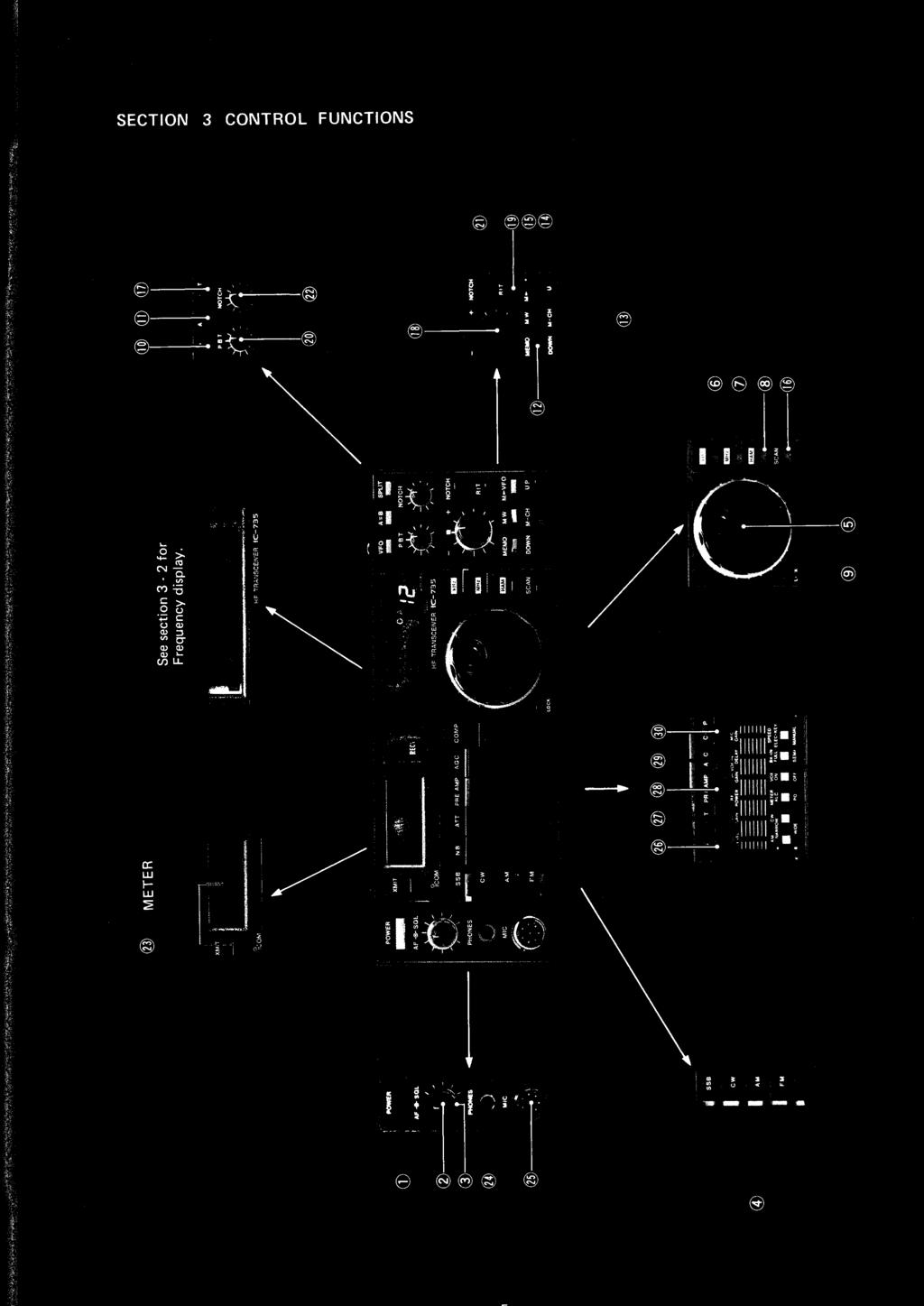
9 SECTION 3 CONTROL FUNCTIONS O O O O O cc 2 O


10 3-1 FRONT PANEL 10 POWER SWITCH This is a push-lock switch which controls the input DC power to the IC-735. When the PS-55 AC power supply is used, the switch also acts as the AC power supply switch. Power is supplied to the transceiver when the switch is pushed in and locked. Power to all circuits is cut (except to the PA unit when using a DC power supply) when the switch is pushed again and released. AF GAIN CONTROL This control varies the audio output level in the receive mode. Clockwise rotation increases the level. 0 SQUELCH CONTROL This control sets the squelch threshold level. To turn off the squelch function, rotate this control completely counterclockwise. To set the threshold level higher, rotate the control clockwise. MODE SELECT SWITCHES These switches select any one of four operating modes; either SSB, CW, AM or FM. Each push of the SSB button alternately selects USB and LSB. Additionally, the "correct" sideband (USB for 10MHz and above, LSB for 7MHz and below) is automatically selected when the HAM switch is pushed. This is explained in greater detail in item 8. () TUNING CONTROL Rotate this control clockwise to increase, and counterclockwise to decrease the frequency. The frequency changes in 10Hz steps in any mode, although the number of steps per dial revolution automatically increases when the control is rotated more rapidly. This control is also used to select the operating band while the HAM button is pushed. khz TUNING RATE SWITCH This switch sets the tuning rate for 1kHz steps. See Section for more information. MHz and HAM buttons have priority over the khz button. 0 MHz TUNING RATE SWITCH This switch sets the tuning rate for 1MHz steps. See Section for more information. The HAM button has priority over the MHz button.


11 C) HAM TUNING RATE SWITCH The transceiver functions on ten bands which include all HF Ham bands from 1.8MHz to 28MHz inclusive. The TUNING CONTROL selects each Ham band in a continuous cycle as shown below when the HAM button is pushed., 1.8MHz/3.5MHz/7MHz/10MHz/14MHz/18MHz/21MHz/24.5MHz/28MHz/29MHz CONTINUOUS CYCLE With the HAM button pushed, the USB mode is automatically selected on the 10MHz band and above, and the LSB mode is automatically selected on the 7MHz band and below. See Section for more information. The HAM button has priority over both the khz and MHz buttons. 0 DIAL LOCK SWITCH This switch electronically locks the display frequency, thus deactivating the TUNING CONTROL. This function is useful after the IC-735 is set to a certain frequency for rag chewing, mobile operation, etc. Disengage the dial lock by pushing and releasing the button again. In the MEMORY CHANNEL mode, this switch activates the Selective Mode Scan so that memories programmed with one particular mode may be monitored. VFO SWITCH This switch selects VFO A or VFO B for tuning purposes. Each oush of this button selects one of the two VFOs alternately. VFO A LSB I. LI Zi 1. LI VFO A 0 Push "VFO" button..(=> VFO B AM t,.q i q ns. 'n VFO B I1 VFO EQUALIZING SWITCH (A=B) This switch instantly matches the frequency and mode of operation of the two VFOs. The display does not change when the A=B button is pushed, however confirmation of the equalizing process is possible by pushing the VFO button to check the frequency and mode of the opposite VFO. VFO A VFO B LSB nnr -on t. I. LI VFO A Push A=B button. LSB nr1cinvfob I. L I _I I. L I I 12 MEMORY READ SWITCH (MEMO) VFO MODE USE nrrnn VFO A in ma 2 L7.3 u. u I C This switch selects the MEMORY CHANNEL mode. The "MEMO" indicator appears on the display, and the "VFO A" or "VFO B" indicator disappears. After pushing the MEMO button, the display indicates the frequency, mode and last memory channel number accessed. Push MEMO button. MEMO MODE The frequency or mode can be changed while in the MEMORY CHANNEL mode but the new frequency and mode information will LSB MEMO nrnn only be saved if the MW (MEMORY WRITE) button is pushed. See LE 3.. u I L. _J item 14 for more information.


12 13 MEMORY CHANNEL UP/DOWN SWITCHES CE3 DOWN M - CH AM t 1.1 t LI. LI n n VFO A U P MEMORY CHANNEL number Each push of these switches increases or decreases the MEMORY CHANNEL. In the VFO mode, only the MEMORY CHANNEL number changes whereas in the MEMORY CHANNEL mode, the MEMORY CHANNEL number, the memorized frequency and the mode change with each push of the UP or DOWN button. Pushing these switches with the dial lock engaged steps through the memory channels programmed with the same mode. MEMORY WRITE SWITCH LSB MD 3.8 _5 LI. LI n n VFO A Push this button to store the displayed operating frequency and mode of operation into a memory channel. Memory writing is possible in either the VFO or MEMORY CHANNEL modes. See page 34 for information on programming the memory channels. Displayed frequency and mode are stored in memory channel 1. 0 FREQUENCY TRANSFER SWITCH This switch operates differently depending on which mode the transceiver is in. LSB 11 n VFO B I. I 1_ ) In the V FO mode, the frequency and mode stored in the memory channel displayed transfers to the selected VFO. Push M VFO button. 2) In the MEMORY CHANNEL mode, the displayed frequency and mode transfers to the VFO used immediately prior to changing to the MEMORY CHANNEL mode. USB can l7 VFO B 5 Stored information in MEMO CH-5 transfers to VFO B and displays when the M VFO button is pushed. NOTE: When in the MEMORY CHANNEL mode, it is the displayed frequency which transfers to the VFO. This is not necessarily the MEMORY CHANNEL frequency since the TUNING CONTROL may have been used to shift the operating frequency. Information stored in the memory channel remains unchanged after using the M VFO function. ED SCAN START/STOP SWITCH SPLIT (DUPLEX) SWITCH 0 RECEIVER INCREMENTAL TUNING This switch alternately starts/stops any of the scan functions. The scan restarts from the stopped frequency in the Programmed Scan mode, and from the highest memory channel in MEMORY CHAN- NEL scan modes. See page 35 for a full description of the various scanning systems available on the IC-735. This switch selects the relationship of the two VFO frequencies. In the OFF position, one VFO is for both receive and transmit. In the ON position, one VFO is for receive while the other VFO is for transmit. Each push of this button alternately chooses the simplex and duplex modes. See page 34 for a full description of simplex/ duplex operation. This control shifts the receiver frequency ±800Hz. RIT RIT SWITCH/RIT LED RIT a This switch turns the RIT circuit ON and OFF. The RIT LED illuminates when the RIT function is active.

 SWITCH C) PHONES JACK This control shifts the NOTCH FILTER frequency.")
13 2 PASSBAND TUNING CONTROL This control allows continuous tuning of the passband selectivity by moving the filter center frequency as much as 1.8kHz either side of the receive frequency in the SSB or CW modes. This feature not only improves the selectivity, but it can also improve the audio tone. The normal control position is at the center (12 o'clock), which provides a filter bandwidth of 2.4kHz in the SSB mode. See page38 for a more detailed explanation. 0 NOTCH FILTER SWITCH This switch turns the NOTCH FILTER circuit ON and OFF. 0 NOTCH FILTER CONTROL 0 T/R (TRANSMIT/RECEIVE) SWITCH C) PHONES JACK This control shifts the NOTCH FILTER frequency. Adjust the control to reduce or eliminate interfering signals. See page 38 for a more detailed explanation. This switch is for manually switching from transmit to receive and vice versa. Set the switch to RECEIVE(out) and the IC-735 is in the receive mode. Set the switch to TRANSMIT(in) and the transceiver switches to transmit. When using the PTT switch on the microphone or the VOX system, the T/R SWITCH must be in the RECEIVE position. This jack accepts a standard 1/4 inch headphone plug from headphones with an impedance of 4 16 ohms. Stereo headphones may be used without modification. MIC CONNECTOR Connect a suitable microphone to this jack. The supplied IC-HM12 hand microphone or the optional SM-8 desk microphone may be used. For different microphones, refer to the diagrams on page 16. FRONT VIEW AF OUTPUT EDMIC INPUT TGND (microphone ground) C2 +8VDC OUTPUT EDGND (PTT ground) F REQ UP/DOWN PTT NC a NOISE BLANKER (NB) SWITCH ATT (ATTENUATOR) SWITCH PREAMP SWITCH Push this switch IN to reduce pulse noise such as that generated by automobile ignition systems. The blanker circuit reduces background receive noise for more enjoyable operating. Additionally, the NB LEVEL CONTROL varies the noise blanker threshold level when the switch is IN. Push this switch IN to remove the RF amplifier from the receive path when strong signals interfere with reception, or make "S" meter readings difficult. For normal operation, leave the switch OUT. This switch turns the receiver preamplifier ON and OFF. Push the switch IN to insert the 10dB preamplifier in the receive path when using a small antenna or receiving a weak signal for added sensitivity. The preamp circuit works at frequencies higher than 1.6MHz.

.")
14 AGC (AUTOMATIC GAIN CONTROL) SWITCH CD COMP (SPEECH COMPRESSOR) SWITCH This switch changes the time constant of the AGC circuit. When the switch is OUT, the AGC voltage reduces slowly for SSB reception. When the switch is IN, the AGC voltage reduces quickly for either CW reception or for receiving signals with rapid fading. This switch turns the speech compressor circuit ON and OFF. The circuit provides greater talk power by improving the intelligibility of the transmitted signal over long distances. 3-2 FREQUENCY DISPLAY The frequency of the IC-735 is displayed on a liquid-crystal display (LCD). The display indicates the carrier frequency using both MHz and khz decimal points when in any mode (USB, LSB, CW, AM, FM). Remember, the displayed frequency does not change when using the R IT function (explained later), although the actual receive frequency does change. The FREQUENCY DISPLAY shows the mode and whether VFO A/B, a memory channel, or the SCAN mode is selected, in addition to the operating frequency. O XMIT RECV LSBUSBCWAM FM' PR t_. 35 n t, I SCAN VFO A VFO B I SPLIT I MEMO j IL O c, FREQUENCY INDICATOR VFO INDICATOR MEMORY INDICATOR MODE INDICATOR TRANSMIT INDICATOR RECEIVE INDICATOR (I) SCAN INDICATOR Shows the operating frequency with 100Hz resolution using 6 digits. Shows the selected VFO; either VFO A or VFO B. Shows whether or not the transceiver is in the MEMORY CHANNEL mode, plus the selected memory channel number. The letters "MEMO" appear when the MEMORY CHANNEL mode is selected. Shows the operating mode; either LSB, USB, CW, AM or FM. Appears when the transceiver is in the transmit mode. Appears when the squelch opens in the receive mode. Shows whether or not the transceiver is in the SCAN mode, in which case, the letters "SCAN" appear. SPLIT INDICATOR Shows the relationship of the two VFO frequencies. One VFO is for receive and the other VFO is for transmit when the letters "SPLIT" appear.


15 3-3 SWITCH PANEL NB RF RF VOX M IC LEVEL GAIN POWER GAIN DELAY GAIN AM CW METER VOX BK-I N NARROW ALC ON FULL DOODD I WIDE PO OFF SEMI SPEED ELEC KEY MANUAL NB LEVEL CONTROL This control varies the threshold level of the noise blanker. Adjust the control to remove noise from the desired signal. C) RF GAIN CONTROL This control varies the gain of the RF stage when the transceiver is in the receive mode. Slide the control upwards for maximum gain. Note that as the control slides downwards, the "S" meter needle rises, and only those signals stronger than the level indicated by the needle will be heard. In the FM mode, regardless of the control setting, the RF gain is fixed at the maximum. RF POWER CONTROL RF POWER This control varies the RF output power from 10 watts to maximum (SSB:100 watts PEP, CW/FM:100 watts, AM:40 watts). Slide the control upwards to increase the output power. VOX GAIN CONTROL Higher sensitivity Lower sensitivity VOX GAIN DELAY VOX ON BK -IN FULL This control increases and decreases the sensitivity of the VOX circuit. When operating in the CW mode, semi break-in or full breakin operation is possible. When operating in the SSB, AM or FM mode, adjust the control so that the circuit activates with a normal speech level. See page 30 for more information. 10 CI OFF SEMI VOX DELAY CONTROL (VOX time constant) This control changes the transmit to receive switching time. Adjust it such that transmit to receive switching does not occur during pauses in normal speech. For CW operation, adjustment depends on the keying speed used. MIC GAIN CONTROL Adjust this control for a suitable modulation level while speaking into the microphone in a normal voice. Slide the control upwards to increase the gain while monitoring the front panel ALC meter. Set the control so the meter needle just begins to move within the ALC zone. This control also varies the speed of the electronic keyer when this feature is used.

 PO: The meter indicates the relative RF output power.")
16 OO FILTER SWITCHES AM CW NARROW I WIDE These switches select the different combinations of the second IF (9MHz) filter and the third IF(455kHz) filter to improve the receiver selectivity. These filters function in conjunction with the Passband Tuning system. See page 31 and 38 for more information. METER SWITCH This switch selects the meter function when in the transmit mode as follows: (1) ALC: The meter indicates the ALC level. The meter begins to give an indication when the RF power reaches a certain value. (2) PO: The meter indicates the relative RF output power. NOTE: The meter switch on the rear panel of the transceiver should be in the PO position in order for the PO meter reading to be accurate. CD VOX SWITCH CW BREAK-IN SWITCH g E LEC-KEY/MANUAL SWITCH This switch turns the VOX circuit ON and OFF. The automatic T/R switching VOX circuit functions in the PHONE and CW modes when the switch is IN. In CW, semi break-in or full break-in operation is possible. Push this switch IN for full break-in CW operation and OUT for semi break-in operation. The VOX SWITCH must also be IN for the BREAK-IN SWITCH to operate. See page 31 for more information. When an optional ELECTRONIC KEYER UNIT is installed, push this switch IN to activate the automatic, iambic keyer, and connect a keyer paddle to the KEY jack on the rear panel of the transceiver. See page 32 for more information on the use of the keyer. The unit installation is described on page REAR PANEL 0 ANTENNA (ANT) CONNECTOR Connect a 50 ohm impedance antenna to this connector. The con- nector mates with a PL-259 plug. cp DC POWER SOCKET Connect the DC power cord from the PS-55 or other suitable power supply here.


17 0 GROUND TERMINAL To prevent electrical shock, TV I, BCI and other problems, be sure to ground the equipment through the GROUND TERMINAL. For best results use the heaviest gauge wire or strap possible and make the connection as short as possible, even in mobile installations. RECEIVER ANTENNA OUTPUT JACK The receive signals from the ANTENNA CONNECTOR pass through the transmit/receive antenna switching circuit to this jack. Normally, the receiver IN and OUT jacks are connected together with a jumper. The ANTENNA OUTPUT JACK is useful when operating with a separate receiver or an external preamplifier. 0 RECEIVER INPUT JACK This is an input jack which connects directly to the receiver front end. TRANSVERTER (X-VERTER) JACK Connect a suitable transverter to this jack for operation on the VHF/UHF frequencies. The output is approximately 30mV. 0 EXTERNAL SPEAKER JACK Connect an external speaker to this jack, if required. Use a speaker with an impedance of 4 16 ohms and remember, the built-in speaker does not function when using the EXTERNAL SPEAKER JACK. KEY JACK For CW operation, connect a CW key here using the supplied standard 1/4 inch, 3-conductor plug. The terminal voltage from external electronic keyers must be less than 0.4 volts DC. When using the IC-735 internal iambic keyer, connect an iambic keyer paddle with a 1/4 inch, 3-conductor plug. 0 ALC JACK (3 SEND JACK This is an input jack for the Automatic Level Control (ALC) lead from a linear amplifier. The ALC input voltage must be in the range from 0 to 4 volts. This jack connects to the transmit/receive relay, and it is grounded when the push-to-talk switch is operated. REMOTE CONTROL JACK ACCESSORY (ACC) CONNECTORS (1), (2) 13 COMP (SPEECH COMPRESSOR) LEVEL CONTROL This is a communications port designed for use with a personal computer to remotely operate the transceiver functions. The jack accepts/transmits serial data by using only one signal and one ground line. These connectors provide signals such as T/R switching, receiver output, etc. See page 24 for detailed information. This control varies the compression level when the COMP SWITCH is pushed IN. The preset circuit gain is approximately 10dB.


18 O MIC TONE CONTROL 0 AM CARRIER CONTROL ANTI-VOX CONTROL I7 METER SWITCH This control varies the transmit audio response. Set the control to produce the clearest and most pleasing audio. Bass response increases as the control is rotated counterclockwise. This control changes the transmit AM carrier level. Adjust with the M IC GAIN set at minimum for a 40 watt carrier or 40% of full scale indication with the METER SWITCH in the Po position. See page 32 for AM operation. When using the VOX mode, speaker audio may sometimes activate the transmitter accidentally. Adjust the ANTI-VOX CONTROL in conjunction with the VOX GAIN in the IC-735 SWITCH PANEL to eliminate this undesired T/R switching. In the transmit mode, this switch selects one of three meter functions. (1) Po: The meter indicates the relative RF output power S dB +60dB RF SWR _ % SET ALC n provided the METER SWITCH in the SWITCH PANEL is set to the PO position. (2) SET: Place the switch in the SET position to measure the standing-wave ratio (SWR) of the antenna system. Adjust the RF POWER CONTROL until the needle rests at the SET position on the meter. (3) SWR: The front panel meter directly reads the antenna system SWR after calibration as explained in step (2).

 2 5. Spare Fuses (3 amp) 2 6. Key Plug 1 7. Microphone (IC-HM12) and hanger.. 1 8.")
19 SECTION 4 INSTALLATION AND CONNECTIONS 4-1 UNPACKING Carefully remove your transceiver from the packing carton and examine it for signs of shipping damage. Should any be apparent, notify the delivering carrier or dealer immediately, stating the full extent of the damage. It is recommended you keep the shipping cartons. They will be handy in the event storage, moving, or reshipment becomes necessary. Accessory cables, plugs, etc., are packed with the transceiver. Make sure you have not overlooked anything. 1. DC Power Cord 1 2. Phono Plugs 2 3. External Speaker Plug 1 4. Spare Fuses (20 amp) 2 5. Spare Fuses (3 amp) 2 6. Key Plug 1 7. Microphone (IC-HM12) and hanger Instruction Manual INSTALLATION RECOMMENDATIONS 1. Avoid placing the IC-735 in direct sunlight, high temperatures and dusty or humid places. 2. The temperature of the transceiver usually becomes relatively high while transmitting. Place any accessory equipment at least 3 centimeters (1 inch) away from the unit so as to provide space for adequate ventilation. Be sure to keep the PA heatsink and the area around it clear of obstructions. Also, avoid locations near heater outlets, air conditioners, etc. 3. Place the unit so that the controls and switches can easily be handled, and the frequency display and meter can be seen clearly. 4. For mobile installations, an optional mounting bracket is available. Select a location which can support the weight of the unit, and that does not interfere with the driver in any way. 5. Use the Ground Terminal! 4-3 ANTENNA Antennas play a very important role in radio communication. If the antenna is inferior, your transceiver cannot give you the best performance. A well-matched 50 ohm antenna and feedline will provide the desired performance. Obtain a quality antenna, preferably one with high gain, which operates on the bands of interest and install it as high as possible. Be especially careful when installing the connectors since poor or loose connections greatly reduce the overall efficiency of the system. Connect the ground terminal of a mobile antenna, if used, to the body of the vehicle.


20 Avoid connecting the ANTENNA CONNECTOR to open feedlines, and do not transmit under mismatched conditions. Operating the transmitter under these conditions could result in damage to the IC-735. Since the IC-735 comes standard with a general coverage receiver, it is recommended that a long-wire antenna and antenna coupler be used. The coupler will ensure there is a matched condition at all times. A Ham band antenna generally does not give adequate performance when used on frequencies for which it was not designed. n MOBILE ANTENNA ICOM's AH-2 HF ALL BAND ANTENNA TUNER can be easily bumper mounted for mobile use, offering automatic band switching and tuning in unison with the IC-735. With a 2.5 meter antenna, the AH-2 can fully cover 3.5 to 30MHz. One push of the TUNE SWITCH on the AH-2 automatically changes the IC-735 emission mode to FM and output power to 10 watts for tuning the AH-2 on the frequency. 4-4 MICROPHONE The supplied IC-HM12 electret condenser hand microphone or optional SM-8 desk microphone may be used. Merely plug it into the MIC CONNECTOR on the front panel. If you wish to use a different microphone, make certain it has the proper output level. Particular care must be exercised when wiring a different microphone since the transceiver internal electrical switching system is dependent upon the correct connections. Refer to the schematics for the proper hookup. Schematic diagram of IC-HM CW KEY For CW operation, connect a CW key to the KEY JACK using the supplied standard 1/4 inch, 3-conductor plug. See the diagrams for connection details. Observe the correct polarity of all leads when wiring. Note that the keyed voltage when switching with semiconductors or relays with resistors in the circuit must be less than 0.4 volts. Wiring for straight key. 9


21 4-6 POWER SUPPLY Use the PS-55 AC power supply when operating the IC-735 from AC power. Refer to the diagram below. CAUTION: Voltages greater than 15 volts DC may damage this transceiver. Check the source voltage before connecting the power cord. To power the IC-735 from your car battery or any other DC power source, be sure the output voltage is 12 to 15 volts and the current capacity is at least 20 amps. The maximum power consumption of the transceiver while transmitting is between 16 and 20 amps. Always turn the transceiver ON after you start the vehicle engine, and remember that a well-maintained battery and electrical system perform better and longer. Connect the AC power supply using the method described below. (1) Make sure the power switch of the transceiver is OFF and the T/R switch is in RECEIVE. (2) Connect the DC power cord to the battery. Attach the RED lead to the positive terminal and the BLACK lead to the negative terminal. Reversing these connections causes the protection fuse to blow. (3) Connect the DC plug to the DC POWER SOCKET on the rear panel of the IC-735. Refer to the diagram below. FOR AC OPERATION WITH THE PS-55 JOo co\l8'sgij O O o 00 0 o ce" IC-735 PS-55 AC OUTLET 0, 1 FOR AC OPERATION WITH OTHER MANUFACTURERS' AC POWER SUPPLY AC POWER SUPPLY DC 13.8V 20A 1 0 O 0 00 o 0 BLACK RED Use the supplied DC power cable. > FOR DC OPERATION WITH DC POWER SOURCE DC POWER CORD CAUTION: Remember to install a FUSE in the DC cord when connecting to a vehicle battery. RED- B LACK BATTERY OR DC POWER SOURCE (12 15V, 20A)


22 4-7 GROUND To prevent electrical shocks, TVI, BCI and other problems, be sure to ground the equipment with the heaviest gauge wire or strap possible from a good earth point to the GROUND TERMINAL on the rear panel. 4-8 LITHIUM BATTERY REPLACEMENT The IC-735 uses an advanced, highly reliable CPU with a long life lithium battery. The purpose of the battery is to provide power to the CPU so it retains all memory information during power failures, or when the unit is unplugged or turned off. The usual life of the lithium battery is approximately five years. After five years of use, it is advisable to monitor the lithium battery carefully and replace it if there are repeated cases of display malfunction. LITHIUM BATTERY NOTE: Battery replacement should be done by your nearest ICOM authorized dealer or ICOM service station. 4-9 FUSE REPLACEMENT (1) Remove the top and bottom covers. (2) Remove the PA UNIT. (3) Remove all screws from the PA unit cover as shown in the diagram. (4) Refer to the photo, and replace the fuse with one which has a 3A rating. n HOW TO REMOVE PA COVER SQUIRREL-CAGE FAN SPACE FOR OPTIONAL ELECTRONIC KEYER FUSE 3A
 w 9 Z j Z c i O o) O (73) a DC POWER SOCK ET 00 00 00 POW ER SWI T C [DO 1] I -111 0 O 0 0 o Lc) 1%) EU 0 C.), C _c fn ya :.E E 0 0 < Ill LIJ 1. I W in W > Z 2?")
 Lr' cr) co to < o Z -J Z u a W o) co E _c Z (:) 4= < REC EIV E A NT I N/OUT J")
23 4-10 REAR PANEL CONNECTIONS IA MBI C PAD D LE CO NNE CTI ONS STRAI G HT K EY CO NN ECTI O N S 1/4 inch key plug is inc lu ded. KEY J AC K co 1:3 ci) CC O E c.) w 9 Z j Z c i O o) O (73) a DC POWER SOCK ET POW ER SWI T C [DO 1] I O 0 0 o Lc) 1%) EU 0 C.), C _c fn ya :.E E 0 0 < Ill LIJ 1. I W in W > Z 2? P o 0 I < i- 1 (7, 0 0 Ow w u)a. z Z W > > z co co oi ri 0 EXTERNAL SPEAKER JAC K co CC 0 C o c; w E Z C Z 0 S 0 0 c) Lr' cr) co to < o Z -J Z u a W o) co E _c Z (:) 4= < REC EIV E A NT I N/OUT J ACKS No rma l ly jo ined with a ju mp e r ca ble. An te nna Switc h w L).1) CU C 4., O. o {57 C 0 OL7- c o E O co 2rj. O 7 a a 4S' E 0


24 SECTION 5 SYSTEM INTERCONNECTIONS 5-1 LINEAR AMPLIFIER The IC-735 is designed to operate into a 50 ohm impedance load. Therefore, any amplifier used must have a 50 ohm input impedance for best efficiency. n USING THE IC-2KL LINEAR AMPLIFIER NOTE: The OPC-118 interface cable to connect the IC-2K L to the IC-735 must be purchased separately. The optional 500 watt, solid-state IC-2KL linear amplifier may be easily connected to the IC-735 with the cables supplied with the amplifier in the same way as other ICOM transceivers. Refer to the the IC-2KL Instruction Manual for details. The connections are shown below. TO ANTENNA COAXIAL CABLE (SUPPLIED WITH IC-2K L) 4 n IC-2K <.> 1:: :1 TO IC-2K LPS L (SUPPLIED WITH IC-2KL) ACC CABLE _L 0 EARTH GROUND OPC-118 (AVAILABLE SEPARATELY) C) o o o o IC-735 DC 13.8V n USING OTHER MANUFACTURERS' LINEAR AMPLIFIERS The SEND jack on the rear panel of the transceiver supplies the output from a built-in keying relay for a linear amplifier. The ALC jack is an input for the automatic level control signal from a linear amplifier. The specification for the keying relay is DC 24 volts maximum. Do not exceed this limit. If the transmit/receive circuit of the linear amplifier requires greater voltage than the above value, a larger relay must be installed between the amplifier and the transceiver. The SEND jack is grounded while the transceiver is in the transmit mode and it opens when the transceiver returns to the receive mode. The output condition of this jack does not control either the transmit or receive function of the transceiver. TO ANTENNA 50 OHM COAXIAL CABLE P L-259 IC RF OUT RF IN 0 0 DC 13.8V LINEAR AMPLIFIER A LCO ld SENDO =0 o o o 00 A LC SEND PHONO PLUGS


25 5-2 ANTENNA TUNER It is recommended that the ICOM AT-150 automatic antenna tuner be used between the IC-735 and the antenna system to achieve maximum performance from the transceiver. The IC-735 may also be used with the earlier IC-AT100 or IC-AT500 antenna tuners as shown in the diagram. All three models have automatic band changing controlled by a voltage supplied from the IC-735. See page 24 for more information. n USING THE AT-150 The AT-150 is the antenna tuner designed for use with the IC-735 transceiver. Both units have matching styles and dimensions. See the AT-150 instruction manual for more detailed information. COAXIAL CABLE (SUPPLIED WITH AT-150) AT-150 IC-735 O ( I R1* o = O 13.8V DC ACCESSORY CABLE (SUPPLIED WITH AT-150) n USING THE IC-AT100/500 The OPC-118 interface cable to connect the IC-AT100/500 to the IC-735 must be purchased separately. COAXIAL CABLE (SUPPLIED WITH IC-AT100/500) TO ANTENNA (SUPPLIED WITH IC-AT100/500) ACCESSORY CABLE OPC-118 (AVAILABLE SEPARATELY) 101 o o p 0 O11 = I I I C-AT100/ o o C) o 0 o 0 0 IC DC 13.8V _L NOTE: Power switch must be turned off when ACC cable is plugged in or removed. 5-3 RTTY OPERATION With the IC-735, RTTY contacts may be enjoyed by using AFSK (audio frequency shift keying). The demodulator used should have 2125/2295MHz filters for narrow shift (170Hz) operation. Place the IC-735 in the LSB mode.
 can be used with the IC-735.")
 AFSK GENERATOR See page 9 for mic connector connections. 0 USING ACC (1) CONNECTOR ACC (1) RTTY DEMODULATOR ITU) 60mA or 20mA LOOP TTY MACHINE SELECTOR MAGNETS LOOP CURRENT POWER SUPPLY Mt?")
26 CONNECTIONS n USING THE AFSK GENERATOR For RTTY operation, a teletypewriter (or an equivalent) and a demodulator (terminal unit) which is operational with audio input are required. Any demodulator with 2125/2295Hz filters (narrow, 170Hz shift) can be used with the IC USING MIC/PHONE JACKS PHONE JACK RTTY DEMODULATOR 60mA or 20mA ITU) "'"-- LOOP LOOP CURRENT POWER SUPPLY TTY MACHINE SELECTOR MAGNETS ttttti BREAK SWITCH C.2) AFSK GENERATOR See page 9 for mic connector connections. 0 USING ACC (1) CONNECTOR ACC (1) RTTY DEMODULATOR ITU) 60mA or 20mA LOOP TTY MACHINE SELECTOR MAGNETS LOOP CURRENT POWER SUPPLY Mt?! BREAK SWITCH AFSK GENERATOR See page 24 for ACC connector information FREQUENCY READOUT (1) Place the IC-735 in the LSB mode when operating RTTY using AFSK. (2) When operating in this manner, there is a difference between the display frequency and the actual operating frequency. ED RECEIVING Assuming the demodulator mark frequency is 2125Hz and the space frequency is 2295Hz: Transmit frequency of contacted station = Displayed frequency 2125Hz TRANSMITTING Assuming the AFSK generator mark frequency is 2125Hz and the space frequency is 2295Hz: Transmit frequency of your station = Displayed frequency 2125Hz
 to pin 4 on the ACC (1) connector on the rear panel of the IC-735.")

27 (EXAMPLE) You wish to operate RTTY using AFSK on MHz. 1. Place the IC-735 in the LSB mode. 2. Set the IC display frequency to MHz. 3. Apply AFSK signals (2125Hz mark, 2295Hz space) to pin 4 on the ACC (1) connector on the rear panel of the IC INSTALLING OPTIONAL ELECTRONIC KEYER This unit provides an automatic keying function with an iambic paddle, and it is built with a single CMOS IC. Features designed into this IC include contact debouncing, RF immunity, self-completing character generation, dot memory and weight control. The keying speed can be changed between 5 and 45 wpm by the MIC GAIN/ SPEED CONTROL on the switch panel of the set. 1. Install the unit into the position shown in the illustration using the attached screws. 2. Unplug P27 which is presently connected to J23 on the PL board (See page 44 for the location.) and connect P27 to connector, J1 (P36) on the keyer unit. NOTE: See page 45 for transceiver disassembly. 3. Plug the 4 pin connector, P28 from the PL board into J2 (P37) on the keyer unit. Wiring for an iambic paddle. 4. Connect an iambic paddle with a 3-conductor 1/4 inch key plug as shown in the figure. DOT DASH.0. tl 5. Check the operation of the keyer. If you would like to increase the weight, turn the weight control on the unit clockwise for your favorite position. See page 32 for operating instructions. P27 WEIGHT CONTROL (R2),e ELECTRONIC KEYER FROM MAIN UNIT PA UNIT 5-5 INSTALLING OPTIONAL CW NARROW FILTER There are two types of optional CW filters as follows: CENTER FREQUENCY CHARACTERISTICS F L-32A MHz 500Hz/-6dB, 1.6kHz/-60dB FL-63A MHz 250Hz/-6dB, 1.1 khz/ -60dB The optional filter should be installed on the MAIN unit as shown in the picture. See page 43 for the location. OPTIONAL CW FILTER
: Connect a phone patch or AFSK RTTY equipment here. ACC (2): Connect an AT-150, IC-AT100 or IC-AT500 automatic antenna tuner here.")
 pin 2. SEND IC-735 switches to the transmit mode when this pin is grounded. MOD Input to the modulator stage for AFSK signals.")
28 5-6 ACCESSORY CONNECTORS The DIN type ACCESSORY CONNECTORS and one mini-jack are installed on the rear panel of the IC-735. The function of each connector is as follows: ACC (1): Connect a phone patch or AFSK RTTY equipment here. ACC (2): Connect an AT-150, IC-AT100 or IC-AT500 automatic antenna tuner here. REMOTE JACK: Connect a personal computer through the CT-17 CI-V LEVEL CONVERTER for remote control of the transceiver functions. ACC (1) (t) NC No connection. GND Ground. Connected in parallel with ACC (2) pin 2. SEND IC-735 switches to the transmit mode when this pin is grounded. MOD Input to the modulator stage for AFSK signals. (8) AF Output from the receiver detector stage. This is a fixed level regardless of the AF gain setting or AF output. SQLS This terminal goes to ground level when the SQUELCH C7 13.8V (8) ALC opens. The letters RECV appear on the front panel display at the same time. 13.8V DC output switched by the main POWER SWITCH on the front panel. Connected in parallel with ACC (2) pin 7. Input for external ALC voltage. Connected in parallel with ACC (2) pin 5. ACC (2) ACC (2) 0 8V Output reference voltage for band switching. 0 GND Ground. 0 SEND Same as ACC (1). BAND Output for external band switching. See the NOTE below. ALC Input for external ALC voltage. Same as ACC (1) pin 8. 0 TR V Input for TRANSVERTER control. The IC-735 will operate with a transverter when 8V DC is applied to this pin V Same as ACC (1) pin 7. NOTE: The IC-735 outputs a band control voltage when the band of operation is changed. This signal automatically switches accessory equipment such as the ICOM linear amplifier or antenna tuners. BAND CONTROL VOLTAGE CHART BAND (MHz) BAND CONTROL VOLTAGE V V V V V V V
 If a power supply other than the PS-55 is used, check that the DC output voltage is 13.8 volts DC.")
 Check all connections between the IC-735 and accessory equipment. Open the hinged SWITCH PANEL plastic cover by pulling lightly on its handle located at the upper right corner of the panel cover.")
29 SECTION 6 OPERATING INSTRUCTIONS 6-1 SETTINGS After all INSTALLATION AND CONNECTION instructions have been followed in SECTION 4, including connecting a 50 ohm antenna system, set the controls and switches as indicated below. (1) If a power supply other than the PS-55 is used, check that the DC output voltage is 13.8 volts DC. (2) Check that the antenna connector on the feedline from the antenna is securely fastened to the ANTENNA CONNECTOR on the rear panel of the IC-735. (3) Check all connections between the IC-735 and accessory equipment. Open the hinged SWITCH PANEL plastic cover by pulling lightly on its handle located at the upper right corner of the panel cover. To remove the cover completely, open it to the horizontal position and pull outward. SWITCH/CONTROL AF GAIN CONTROL SQUELCH CONTROL XMIT SWITCH NB SWITCH ATT SWITCH PREAMP SWITCH AGC SWITCH COMP SWITCH LOCK SWITCH khz SWITCH MHz SWITCH HAM SWITCH PBT CONTROL NOTCH CONTROL RIT CONTROL RIT SWITCH SWITCH PANEL POSITION 10 O'CLOCK MAXIMUM COUNTERCLOCKWISE OFF (OUT) WITH NO "XMIT" OFF (OUT) OFF (OUT) OFF (OUT) SLOW (OUT) OFF (OUT) OFF (OUT) OFF (OUT) OFF (OUT) OFF (OUT) CENTER (DETENT) CENTER CENTER OFF (OUT) REFER TO THE FOLLOWING DIAGRAM. NOTE: Set each slide control as shown in the diagram. All switches should be OUT. AM CW NARROW 1 WIDE NB RF RF r VOX MIC LEVEL GAIN POWER GAIN DELAY GAIN U BK-IN SPEED AM CW METER VOX NARROW ALC ON FULL ELEC KEY The receiver audio is muted when no optional filter is installed and the CW NARROW SWITCH is pushed. WIDE PO OFF SEMI MANUAL


30 6-2 BASIC OPERATION The following instructions are for using the IC-735 in any mode. Please read and understand them carefully before turning ON your transceiver. After setting each control and switch as described in 6-1, push the POWER SWITCH IN. The meter and the frequency display lamp illuminate and a frequency, mode, VFO, memory channel number, etc. appear on the LCD FREQUENCY SELECTION The IC-735 transmitter covers all HF Ham bands while other frequencies are muted. In addition, the receiver covers all frequencies from 0.1 to 30MHz continuously. Rotate the TUNING CONTROL clockwise to increase the frequency, and counterclockwise to decrease the frequency in 10Hz steps when no step select buttons are pushed IN. EMI LI1111n11 SCAN ILA (1) khz SWITCH Push this button and rotate the TUNING CONTROL to change frequency in 1kHz steps. The 100Hz digit automatically clears to "0" when the switch is pushed. (2) MHz SWITCH Push this button and rotate the TUNING CONTROL to change frequency in 1MHz steps. The 100kHz, 10kHz, 1kHz and 100Hz digits do not change during this operation. The MHz SWITCH has priority over the khz SWITCH. (3) HAM SWITCH TRANSMIT FREQUENCIES BAND FREQUENCY COVERAGE 1.8M Hz MHz The transceiver functions on the bands which include all HF Ham bands from 1.8MHz to 28MHz inclusive. Push this button and rotate the TUNING CONTROL to select each HAM band in a continuous cycle as shown below. 3.5M Hz MHz 7 MHz M Hz 10 MHz M Hz 14 MHz MHz 1.8MHz 3.5MHz -4-7MHz > 10MHz - 14MHz I 29MHz < 28MHz M H z < 21MHz < 18MHz < 18 MHz MHz 21 MHz MHz 24.5MHz MHz 28/29M Hz MHz NOTE: The IC-735 transmits in the ranges shown in the table, however it is the operator's responsibility to follow the pertinent government radio regulations. When changing from one Amateur band to another with the HAM SWITCH pushed, in all cases except 1.8MHz, the VFO automatically rests at the frequency on the adjacent Amateur band which is in the same relative position with respect to the newly selected band as was the previously used frequency with respect to the previous band. For example, beginning from 3.6MHz and rotating the TUNING CONTROL clockwise with the HAM SWITCH pushed selects 7.1, 10.1, 14.1, 18.1, 21.1, 24.6, 28.6, and 29.6MHz, consecutively. This feature permits very rapid frequency shifts to other bands so that contacts on the same mode may be completed with almost no adjustment or tuning of the transceiver. When changing to or from the 1.8MHz band, the 100kHz, 10kHz, 1kHz, and 100Hz digits selected on the adjacent band, that is 3.5 or 29MHz, do not change. Also, with the HAM SWITCH pushed, the USB mode is automatically selected on the 10MHz band and above, and the LSB mode is automatically selected on the 7MHz band and below. The HAM button has priority over both the khz and MHz buttons.
 Rotate the TUNING CONTROL continuously and smoothly in one direction.")

31 n BRAKE ADJUSTMENT The TUNING CONTROL tension may be adjusted to suit the operator's preference. The screw adjustment is located on the bottom side of the transceiver cabinet below the TUNING CONTROL. The method for adjustment is as follows: (1) Rotate the TUNING CONTROL continuously and smoothly in one direction. (2) Adjust the brake adjustment screw either clockwise for tighter tension, or counterclockwise for looser tension as desired. Brake adjustment screw It is unnecessary to remove the bottom cover for the brake adjustment MODE SELECTION Simply push any one of the four MODE SWITCHES to select an operating mode. (1) SSB The USB mode is automatically selected on the 10MHz band and above, and the LSB mode is automatically selected on the 7MHz band and below. The mode changes alternately between USB and LSB each time the SSB button is pushed. (2) CW (3) AM (4) FM See CW OPERATION. See AM OPERATION. See FM OPERATION VFO A/B SELECTION VFO ILI The IC-735 contains two VFOs for both receiving and transmitting. The VFOs are called VFO A and VFO B, and they may be selected alternately by pushing the VFO SWITCH when in the VFO mode. This dual VFO system provides a great deal of operating flexibility, therefore read this section carefully and try the example for yourself in order to become proficient at using this important feature. (1) When VFO A is selected, "VFO A" appears on the LCD and both transmit and receive frequencies are as indicated on the frequency display. This frequency and the mode are stored in memory "A". (2) When VFO B is selected, "VFO B" appears on the LCD and both transmit and receive frequencies are as indicated on the frequency display. This frequency and the mode are stored in memory "B". Switching from one VFO to the other VFO does not clear the first VFO. The VFO's memory retains the frequency and operating mode.


32 (Example) USB -or III I r. c 1.7 VFO A Lt JI Select the frequency MHz and USB using VFO A. Push the VFO SWITCH, and the frequency display shows the frequency and mode that is stored in VFO B. The frequency MHz and USB are still stored in VFO A, however. Push the VFO SWITCH to select VFO B. Push the VFO SWITCH again and the VFO A information appears on the LCD. Push the VFO SWITCH once more to display the VFO B information. cm /. 36 an VFO USB B Push the VFO SWITCH to select VFO B. Push the VFO SWITCH again to return to VFO A. Push the VFO SWITCH again to return to VFO A. This allows you to set a certain frequency in one VFO, tune up or down the band as desired with the opposite VFO searching for other stations, and then return quickly and easily to the first frequency by simply pushing the VFO SWITCH. r USB c t. VFO A VFO MODE/MEMO MODE SELECTION 6-3 RECEIVING (1) POWER ON (2) VFO A/B SELECTION (3) MODE SELECTION (4) AF GAIN ADJUSTMENT Push the MEMO SWITCH to change the transceiver from the VFO mode to the MEMORY CHANNEL mode. Any of the frequencies stored in the 12 memory channels may now be selected and used. To change back to use the VFOs again, push the VFO SWITCH. Set the controls and switches as indicated in Section 6-1, then continue with the following procedure. Push the POWER SWITCH to turn ON the power. Push the VFO SWITCH to select either VFO A or VFO B. Push one of the mode switches to select the desired operating mode. Adjust the AF GAIN for an appropriate audio level from the speaker. Clockwise rotation increases the level of audio. n AF TONE ADJUSTMENT No covers need to be removed for the adjustment. (5) SQUELCH ADJUSTMENT Adjust this control for the clearest and most pleasing receive audio. The control is located on the bottom side of the transceiver, and may be adjusted without removing the cover. See the photo on page 43 for the exact location. Set the squelch threshold level. Place the control fully counterclockwise to disable the squelch circuit, and rotate clockwise to raise the threshold level. (1) Push the AGC SWITCH IN. (2) Set the RF GAIN control for a reading of, for example, S9 on the meter. (3) Rotate the SQUELCH CONTROL until the "RECV" indication on the LCD just disappears. Only those signals greater than an S9 level will be audible. (6) TUNING Refer to Section , FREQUENCY SELECTION, and rotate the TUNING CONTROL until a signal is audible. If it is a phone signal but not intelligible, check that the receiver is set to the correct sideband (USB or LSB) for the band of operation.


33 6-4 TRANSMITTING (1) USING THE PTT (PUSH-TO-TALK) or XMIT SWITCH PTT SWITCH XMIT Before transmitting, listen in the receive mode to make sure your transmission will not interfere with other communications. Use a dummy load instead of the antenna for preliminary transmitter tuning. Leave the other controls and switches in the same position as for the receive mode. Push the PTT SWITCH on the microphone or the XMIT SWITCH on the front panel, and the "XMIT" indicator appears on the LCD. Speak into the microphone in a normal voice, and note that the meter needle follows your voice modulation. This indicates the SSB signal is transmitting. Set the MIC GAIN to keep the ALC METER reading well within the designated ALC zone on the meter at voice peaks. Adjust the RF POWER CONTROL to obtain the desired power between approximately 10 and 100 watts. Change back to the receive mode by releasing the PTT SWITCH or by pushing the XMIT SWITCH again. (2) USING VOX (VOICE OPERATED TRANSMIT) (3) CW BREAK-IN The VOX function allows hands-off transmissions since the transmitter is turned ON and OFF by means of your voice. See page 30 for a full description of the VOX function. When operating CW, the transmit/receive switching may be controlled by the keying action rather than by manual operation by the operator. See page 31 for a full description of CW break-in. n CONTINUOUS TRANSMITTING NOTE: The fan never operates while in the receive mode. The IC-735 has a squirrel-cage fan installed on the PA unit for cooling purposes. A protection circuit controls the fan operation such that the fan supplies cool air at a low speed at the beginning of a transmission. When the PA unit reaches a temperature of 50 C, the fan motor increases to middle speed. A PA temperature of 90 C causes the fan to run at the highest speed. Under normal operating conditions, the IC-735 will continue to transmit with no power reduction in an ambient temperature of 25 C even when transmitting for long periods. 6-5 OPERATION SSB OPERATION Set all controls and switches as described in Section 6-1. (1) SSB RECEIVING 1. Push the POWER SWITCH IN. USB I n 1331 C t.i b u.s_t VFO A 2. Push the SSB SWITCH to select either USB or LSB mode. 3. Push the HAM SWITCH and rotate the TUNING CONTROL to select the desired band of operation. Push the HAM SWITCH again to place it in the OUT position and the HAM function is disabled. 4. Adjust the AF GAIN CONTROL for the desired volume. 5. Rotate the TUNING CONTROL and search for a signal. Tune across the signal to peak the meter needle while listening for the most intelligible audio.


34 (2) SSB TRANSMITTING dB +60dB Ak \ Lmbid RF % SWR i SET ALC I 1. Listen carefully before transmitting to be sure your transmission does not interfere with any other communications. 2. Push the XMIT SWITCH or the PTT SWITCH to place the transceiver in the transmit mode. 3. Set the METER SWITCH to the PO position (OUT). Speak into the microphone in a normal voice and the meter needle will follow your voice modulation to indicate that the SSB signal is transmitting. RF MIC POWER GAIN 1 I METER SPEED ALC ELEC KEY 13 0 PO MANUAL NOTE: The "XMIT" indicator appears whenever the IC-735 is placed in the transmit mode, however an RF signal is only transmitted when the operating frequency selected is within an Amateur band. 4. Set the METER SWITCH to the ALC position (IN), and adjust the MIC GAIN for a meter reading within the ALC zone on voice peaks. (3) VOX OPERATION Set the VOX GAIN, VOX DELAY and MIC GAIN as shown in the diagram before beginning. 1. Push the VOX SWITCH to activate the VOX circuit. Leave the XMIT SWITCH in the receive position (OUT) and do not push the PTT SWITCH on the microphone. 2. Slide the VOX GAIN CONTROL upwards while speaking into the microphone. When the T/R switching circuit activates, stop adjusting the VOX GAIN CONTROL. Speak into the microphone in a normal voice for an accurate setting of this control. 3. The VOX DELAY CONTROL varies the amount of delay before the transceiver returns to the receive mode after your speaking stops. Slide this control downwards to reduce the time delay. Set it at the position which allows for short pauses in normal speech without dropping back to the receive mode. 4. Rotate the ANTI VOX CONTROL on the rear panel clockwise while receiving a signal until the audio from the speaker does not activate the VOX circuit. See page 12 for the exact location. (4) USING THE SPEECH COMPRESSOR The IC-735 has a low distortion, AF speech compressor circuit which provides greater talk power by improving the intelligibility of the transmitted signal over long distances. 1. Push the COMP SWITCH to activate the compressor circuit. 2. The speech compressor is factory set for a value of approximately 10dB. Switch to transmit and adjust the COMP LEVEL CON- TROL on the rear panel if a different value of compression is preferred. See page 12 for the exact location of the COMP LEVEL CONTROL. NOTE: The speech compressor should be turned OFF or MIC GAIN CONTROL carefully set for minimum compression for all communication other than DX operation for very natural voice quality.


35 CW OPERATION Push the CW MODE SELECT SWITCH to operate on CW. The other controls and switches should be set the same as described for SSB reception. See page 19 for CW key connections. (11 CW RECEIVING 1. Push the POWER SWITCH to turn the power ON. 2. Push the CW MODE SWITCH. 3. Set the desired operating frequency. 4. Adjust the AF GAIN CONTROL for a suitable volume. *See page 23 for the optional filter characteristics. *Receiver audio is muted with neither filter installed. 5. The Passband Tuning system may be used to narrow the receiver selectivity down to 800Hz with maximum counterclockwise rotation of the PBT CONTROL, and to 2.3kHz with maximum clockwise rotation. Additionally, the NOTCH FILTER eliminates specific interference at discrete frequencies within the passband of the receiver. 6. If an optional CW narrow filter is installed, push the CW NAR- ROW SWITCH to select the narrow filter, thereby improving the receiver selectivity. Selectivity is 500Hz/-6dB with the FL-32A filter selected, and 250Hz/-6dB with the FL-63A filter. Background noise is reduced and the signal-to-noise ratio is improved with the narrow filter, providing more enjoyable listening conditions. (2) CW TRANSMITTING 1. Insert the CW key plug into the KEY JACK on the rear panel of the IC Place the METER SWITCH in the PO position. Wiring for a hand key or external electronic keyer. 3. Push the XMIT SWITCH to place the transceiver in the transmit mode. No imielp111.1gwis ' I See next page for automatic keying operation. 4. Operate the CW key and note that the meter needle moves in time with the CW sending. This indicates the CW signal is transmitting. 5. Adjust the VOX DELAY CONTROL while sending CW so that the transmit/receive switch does not operate during short pauses. n CW SIDETONE MONITOR No covers need to be removed to adjust the MONI- TOR LEVEL CONTROL. An 800Hz sidetone oscillator is provided to monitor keying when in the CW mode. The MONITOR LEVEL CONTROL varies the loudness of the tone. This control is located on the bottom side of the transceiver. See page 43 for the exact location of the adjustment. Rotate the MONITOR LEVEL CONTROL clockwise to increase the loudness of the oscillator tone. The receiver AF GAIN CONTROL also varies the loudness. (3) SEMI/FULL BREAK-IN OPERATION The IC-735 has both semi break-in and full break-in CW capability when using the VOX function. This means the transmit/receive switching is performed automatically by the transceiver whenever the keying starts or stops. The receive to transmit switching time is, practically speaking, instantaneous whereas the transmit to receive switching time may be varied by an adjustment to suit an individual's keying speed.
 to select semi break-in operation, or to the FULL position (IN) to select full break-in operation. 3.")

36 1. Push the VOX SWITCH to the ON position (IN). VOX GAIN DELAY 2. Push the BK-IN SWITCH to the SEMI position (OUT) to select semi break-in operation, or to the FULL position (IN) to select full break-in operation. 3. Place the XMIT SWITCH in the receive position (OUT). VOX ON OFF BK-IN FULL SEMI 4. Begin sending with the CW key and the transmitter will switch between transmit and receive automatically. 5. Set the transmit release delay time to suit your keying speed by adjusting the VOX DELAY CONTROL on the rear panel. Rotate the control clockwise to increase the transmit release delay. (4) AUTOMATIC KEYING USING OPTIONAL ELECTRONIC KEYER Wiring for an iambic paddle. DOT DASH com Automatic keying is possible by operating with the optional electronic keyer simply by connecting an iambic paddle to the IC-735. The purpose of the electronic keyer is to simplify CW keying by generating dots and dashes with proper length-to-space ratios. The operator merely controls the number of dots or dashes transmitted without regard to spaces between the elements, or the timing of the elements within a character. When used correctly, the resulting CW is generally easier and more enjoyable to copy at the receiving end. MIC GAIN 1. Insert the CW key plug into the KEY JACK on the rear panel of the IC Push the ELEC-KEY SWITCH to the IN position. SPEED ELEC KEY MANUAL 3. Begin sending and adjust the dual function MIC GAIN/SPEED CONTROL for a suitable keying speed. 4. Push the VOX SWITCH to the ON position (IN). 5. The transmit/receive switching is automatically performed by the transceiver. The CW WEIGHT CONTROL is installed on the electronic keyer. See page 23 for the exact location. 6. The transmit release delay time is set in the same manner as with semi/full break-in operation AM OPERATION (1) AM RECEIVING NB LEVEL RF GAIN Push the AM MODE SELECT SWITCH to place the transceiver in the AM mode. Set the other controls in the same way as for SSB reception. The Passband Tuning circuit does not function in the AM mode. 1. Push the POWER SWITCH to the ON position (IN). 2. Select the desired band of operation. AM CW NARROW 3. Push the AM MODE SWITCH. 1 WIDE 4. Tune in an AM signal with the TUNING CONTROL using the meter to peak the signal. 5. Push the AM FILTER SWITCH to the NARROW position (IN) to select the narrow receive selectivity. The selectivity used is the same as for SSB when this narrow position is selected.


37 (2) AM TRANSMITTING dB +60dB Transmitting an AM signal is essentially the same as for SSB transmission. 1. Push the METER SWITCH to select the PO position (OUT). RF SWR.52 3 ALC SET 2. Turn the transmitter ON by using either the XMIT SWITCH or the PTT SWITCH on the microphone. ALC INDICATION 3. Adjust the carrier level for a 40% of full scale reading using the RF scale and the CARRIER LEVEL CONTROL located on the rear panel of the IC-735 when the RF POWER CONTROL is at the maximum position. Alternately, adjust the CARRIER LEVEL CONTROL for a carrier output power of 40 watts. See page 12 for the location of the CARRIER LEVEL CONTROL. If the RF POWER CONTROL is not at the maximum position, first transmit using the FM mode. Remember the RF indication on the meter, then adjust the CARRIER POWER CONTROL for 40% of this RF meter indication. 4. Push the METER SWITCH to select the ALC position (IN). 5. Adjust the MIC GAIN CONTROL for a 1/4 to 1/3 reading in the ALC zone while speaking into the microphone with a normal voice. NOTE: The speech compressor (COMP SWITCH) is functional and can be used on AM FM OPERATION (1) FM RECEIVING 1. Push the FM MODE SELECT SWITCH to place the transceiver in the FM mode. 2. Tune in an FM signal with the TUNING CONTROL using the meter to peak the signal. Tune for the clearest audio. 3. Set the other controls in the same way as for SSB reception. (2) FM TRANSMITTING Transmitting an FM signal is essentially the same as for SSB transmission. 1. Set the MIC GAIN CONTROL to the center position. 2. Turn the transmitter ON by using either the XMIT SWITCH or the PTT SWITCH on the microphone. 3. Speak into the microphone in a normal voice. The meter needle indicates the carrier power when the METER SWITCH is in the PO position (OUT), however the meter does not move in time with the voice modulation in this mode. NOTE: Most countries only allow FM operation on 28MHz or higher. (3) FM REPEATER OPERATION An 88.5Hz TONE ENCODER is often required to access HF FM repeaters. The IC-735 is not equipped with an encoder, but the UT Hz TONE ENCODER is available as an accessory. Install the encoder in the location shown in the photo on page 43. Connect the 3 pin connector from the encoder to the MAIN unit J23 labelled "TONE". When operating through repeaters, input both the transmit and receive frequencies to VFO A and VFO B. The 88.5MHz tone transmits when the FM MODE SWITCH is pushed while transmitting. The tone is transmitted only while pushing the FM MODE SWITCH.

 LSBUSBC WA M FM VFO B B 1.25...I. SPLIT 1. Store the frequency 7.")
38 6-6 SPLIT (DUPLEX) OPERATION (Example 1) Receiving: Transmitting: 7.057MHz 7.255MHz The purpose of the SPLIT function is to allow an operator the option of transmitting and receiving on two different frequencies. Push the SPLIT SWITCH to turn the function ON and OFF alternately. Receiving (VFO LSB n n vf0 A I. L.,/ I. LI SPLIT During split frequency operation, the letters "SPLIT" appear on the front panel display. Transmitting (VFO B) LSBUSBC WA M FM VFO B B I. SPLIT 1. Store the frequency 7.057MHz in VFO A and 7.255MHz in VFO B. 2. Push the VFO SWITCH to select VFO A, and then push the SPLIT SWITCH to select the split function. The letters "SPLIT" appear on the LCD. (Example 2) Receiving: Transmitting: Receiving (VFO A/FM) MHz on FM MHz on USB r CM 25 FM n VFO A 0 gu.0 SPLIT 3. The receive frequency is now set for 7.057MHz and the transmit frequency is 7.255MHz. Push the VFO SWITCH once again to receive on 7.255MHz and transmit on 7.057MHz. Each VFO also stores the operating mode in addition to the operating frequency. This allows crossmode contacts to be made easily. Transmitting (VFO B/USB) Emil USB 853,3 VFO B. _. I SPLIT 6-7 MEMORY CHANNEL OPERATION There are twelve MEMORY CHANNELS numbered 1 through 12 available. One frequency and one associated mode may be assigned to each MEMORY CHANNEL whether the transceiver is in the VFO mode or the MEMORY CHANNEL mode. Remember the following when storing frequencies in memories. MEMO CH-11, CH-12: Used as band limits for the PROGRAM SCAN function. (1) PROGRAMMING MEMORY CHANNELS IN THE VFO MODE (Example) Store MHz/USB in MEMO CH-10. USB am VFO A 1. Push the VFO SWITCH to select either VFO A or VFO B. 2. Push the SSB MODE SWITCH to select the USB mode, and use the TUNING CONTROL to select the frequency MHz. 3. Push either the M-CH UP SWITCH or M-CH DOWN SWITCH to select MEMO CH-10. Push either M-CH UP or M-CH DOWN SWITCH. USB n VFO A, ME tu 4. Push the MW SWITCH to store the frequency and mode into MEMO CH-10. The frequency MHz USB is now stored in MEMO CH-10. (2) PROGRAMMING MEMORY Vacant memories may be programmed or MEMORY CHANNEL CHANNELS IN THE MEMO MODE data may be changed by the following method. (Example) Store MHz/AM in MEMO CH-10. MEMO CH Push either the M-CH UP or M-CH DOWN SWITCH to select AM MEMO n n VFO A in 1c.15 LLD LI 2. Push the MEMO SWITCH to select the MEMORY CHANNEL mode. 3. Push the AM MODE SELECT SWITCH, and use the TUNING MEMO MW CONTROL to select a frequency of MHz Push the MW SWITCH to store the data in MEMO CH-10.
 By changing from one MEMORY CHANNEL to a different MEMORY CHANNEL while in the MEMO mode.")

39 (3) MEMORY RECALL (Example 1) Recall MEMO CH Push MEMO SWITCH. There are two methods of recalling stored information from the MEMORY CHANNELS: a) By changing from one MEMORY CHANNEL to a different MEMORY CHANNEL while in the MEMO mode. MEMO 1n1 b) By shifting the MEMORY CHANNEL number while in the VFO mode, and then transferring the data to either VFO A or VFO B. 2. Push M-CH SWITCH. DOWN M -CH 1. If in the VFO mode, push the MEMO SWITCH to change to the MEMORY CHANNEL mode. If already in the MEMORY CHANNEL mode, proceed to step 2. FM r ( o o su.0 MEMO an I LI 2. Push either the M-CH UP or M-CH DOWN SWITCH to select MEMO CH-10. (Example 2) Transfer MEMO CH-10 data to a VFO. 1. Select either VFO A or VFO B. 2. Select MEMO CH-10. VFO Li DOWN M -CH U P 1. Push the VFO SWITCH to select either VFO A or VFO B. 2. Push either the M-CH UP or M-CH DOWN SWITCH to select MEMO CH Push the M VFO SWITCH to transfer the data from MEMO CH-10 to either VFO A or VFO B, depending which VFO was selected in step 1. LSB 3 n28.0 VFO A 3. Transfer the data to the VFO. lll The frequency display changes to indicate the frequency of MEMO CH-10. NOTE: The frequency display does not change when the M VFO button is pushed if the transceiver is in the MEMORY CHANNEL mode. The frequency does transfer to the VFO, however, and this may be confirmed by pushing the VFO SWITCH. Display changes to MEMO CH-10. usb n VFO A L.Li I I 6-8 SCAN OPERATION (1) PRELIMINARY SETTINGS The IC-735 provides various scanning operations. Read the following instructions carefully, and practice using the different scanning functions to obtain maximum enjoyment from your transceiver. 1. SCAN TIMER ON/OFF All scan modes are provided with the resume scan function. When the scan stops as a result of the auto-stop function, it resumes after a specific amount of time (approximately 10 seconds). This resume feature may be cancelled by turning OFF SWITCH S1 which is located on the PL (PLL-LOGIC) board. See page 44 for the exact location. When the resume function is turned OFF, the scan function clears automatically if a signal is received. The operating frequency remains locked at the frequency of the station which caused the scan to stop. 2. SCAN SPEED Two rates of scanning speed are available. The standard factory setting is at the SLOW speed but the FAST speed may be selected by removing the Jumper Connector from J21, P5 on the PL board. See page 44 for the location of P5.
 PROGRAM SCAN The purpose of this scanning function is to monitor a particular section of the band.")

40 3. SQUELCH CONTROL Rotate the SQUELCH CONTROL clockwise until the "RECV" indicator just disappears to close the squelch circuit. This mutes the audio from the speaker. (2) PROGRAM SCAN The purpose of this scanning function is to monitor a particular section of the band. The frequency limits of the section of band of interest must be programmed in MEMORY CHANNELS 11 and Store the frequencies of the high and low edges of the desired scanning range in MEMORY CHANNELS 11 and 12. See page 34 for instructions on how to write frequencies into memory channels, if required. The scan begins from the low edge of the range regardless of which channel has the higher frequency stored. For example, store MHz in MEMORY CHANNEL 11 and MHz in MEMORY CHANNEL Push the VFO SWITCH to select the VFO you wish to use. Push the correct MODE SELECT SWITCH to place the transceiver in the same operating mode as MEMORY CHAN- NELS 11 and Adjust the SQUELCH CONTROL to mute the audio output from the speaker. NOTE: The auto-stop function sometimes does not stop exactly on the carrier frequency of SSB and CW signals. In these cases, use the TUNING CONTROL or R IT CONTROL to tune in the station. 4. Push the SCAN SWITCH to start the scanning from the low limit (14.200MHz) towards the high limit (14.300MHz). The scanning rate depends on the TUNING RATE SWITCH status. Normally, the scanning steps are 100Hz, however 1kHz steps are used if the khz TUNING RATE SWITCH is pushed. The MHz and HAM SWITCHES have no effect on the scanning rate. When the scan frequency reaches the high limit (14.300MHz), the scan automatically returns to the low limit (14.200MHz) frequency and resumes upwards again in a continuous cycle. 5. The squelch opens when a signal is received, and stops the scanning automatically if the SQUELCH CONTROL has been set as explained under PRELIMINARY SETTINGS, step 3. After approximately 10 seconds, the scan resumes from the frequency that it stopped on in an upwards direction. If the "RECV" indicator remains ON, for example if the SQUELCH CONTROL is turned fully counterclockwise, the scan will not stop at any other signals. 6. Pushing the SCAN SWITCH while the scan is operating or during the 10 seconds of monitoring, clears the scanning function and the VFO returns to normal operation. Transmitting or rotating the TUNING CONTROL also cancels the scanning function. 7. When the operating frequency is lower than the low limit ( MHz) or higher than the high limit (14.300MHz) and the SCAN SWITCH is pushed, the scan immediately jumps to the low limit frequency (14.200MHz) and scans upwards.


41 (3) MEMORY SCAN This is used to scan all programmed memory channels continuously. 1. Program the desired frequencies into memory channels. NOTE: Miscellaneous frequencies were stored in the memory channels at the factory for testing purposes. 2. Adjust the SQUELCH CONTROL to mute the audio output from the speaker. 3. Push the SCAN SWITCH, and the IC-735 begins scanning the programmed channels from the lowest channel towards the highest channel. 4. Provided the squelch is closed when the scan begins, the scan stops when a receive signal opens the squelch. After a fixed time, the scan resumes. 5. Push the SCAN SWITCH to stop the scanning function manually. Push the SCAN SWITCH again to resume scanning. (4) MODE SCAN 1. Store the frequencies and modes in the desired MEMORY CHANNELS. The purpose of this scan is to selectively monitor those memory channels which contain frequencies programmed with the same mode, that is USB, LSB, CW, AM or FM. 2. Push the MEMO SWITCH. MEMO 3. Set the SQUELCH CONTROL. 1. Store the desired frequencies and modes in the memory channels. 2. Push the MEMO SWITCH to place the transceiver in the MEM- ORY CHANNEL mode. 3. Adjust the SQUELCH CONTROL to mute the audio output from the speaker. 4. Select the correct mode with the M-CH SWITCH. DOWN M-CH U P 4. The MODE SCAN only stops on the channels which have the same mode as the channel from which the scan begins. Therefore, use the M-CH UP or the M-CH DOWN SWITCH to select a memory channel which has the same mode as you wish to scan. 5. Push the LOCK SWITCH. 5. Push the LOCK SWITCH which is located to the lower left of the TUNING CONTROL to the ON position (IN). 6. Push the SCAN SWITCH. The transceiver begins from the channel selected in step 4, and steps through each memory channel with the same mode stopping only when a receive signal is detected. LOCK SWITCH 6. Push the SCAN SWITCH. 6-9 MICROPHONE UP/DOWN FUNCTION The operating frequency increments or decrements one step with each push of the UP(up) or DN(down) switch, respectively, on the (1) FREQUENCY UP/DOWN FUNCTION microphone. Holding either switch down causes the transceiver to tune continuously in either the upwards or downwards direction in the same manner as rotating the TUNING CONTROL. The TUN- ING RATE SWITCHES determine the rate of tuning across the band. NOTE: MEMORY CHANNEL selection cannot be controlled from the microphone with the UP/DN SWITCHES. Frequency control is possible whether in the VFO mode or the MEMORY CHANNEL mode.

 position.")
42 (2) UP/DOWN SCANNING SPEED Two rates of scanning speed are available. The standard factory setting is for the SLOW speed but the FAST speed may be selected by removing the Jumper Connector from J21, P5 on the PL board. See page 44 for the location of P FILTERS PASSBAND TUNING (P.B.T.) Passband Tuning is a system designed to electronically narrow the bandwidth (selectivity) of frequencies that will pass through the crystal filter. The PBT CONTROL may also be used to adjust the tone of the receive audio for maximum intelligibility. The PBT CONTROL has a detent position at the center (12 o'clock) position. This position provides the widest bandwidth, and the control should normally be left in this position. While receiving in the LSB mode, narrow the bandwidth by turning the PBT CONTROL counterclockwise to eliminate interference from lower frequencies (interfering signals are high-pitched). Turn the PBT CONTROL clockwise to eliminate interferbnce from higher frequencies (interfering signals are low-pitched). NOTE: The Passband Tuning function does not function when the transceiver is in the AM or FM modes since the maximum shift of the Passband system is only ±1.8kHz compared with the 6kHz AM filter and the 15kHz FM filter. While receiving in the USB mode, the bandwidth is reduced in the opposite manner. Narrow the bandwidth by turning the PBT CONTROL clockwise to eliminate interference from higher frequencies (interfering signals are high-pitched). Turn the PBT CON- TROL counterclockwise to eliminate interference from lower frequencies (interfering signals are low-pitched). Receiving LSB signal When the passband shifts to the right. Receiving LSB signal When the passband shifts to the left. I I I L Interfering signal B FO frequency Interference Receive signal [[ Passband is narrowed and interfering signal goes out of the passband. B F O frequency Passband is narrowed tre signal and interfering signal Interference goes out of the passband. Interfering signal NOTCH FILTER This circuit provides high attenuation at one particular frequency in the IF passband. It may be used to reduce or eliminate interfering heterodyne signals that fall within the passband of the receiver. Push the NOTCH FILTER SWITCH to the ON position (IN), and rotate the NOTCH FILTER CONTROL slowly to minimize the interference FILTER SWITCHES NB RF LEVEL GAIN These switches select the different combinations of the internal receive filters. WIDE (. ) NARROW ( AM CW NARROW D WIDE AM 6 khz 2.3kHz CW 2.3kHz * 250Hz or 500Hz * FL-32A 500Hz/-6dB) and FL-63A (250Hz/-6dB) are available as an option. Receiver audio is muted with neither installed.

 and select the USB mode. Listen for WWV/WWVH. 2. Turn ON the 25kHz MARKER SWITCH, S2 located on the PL board by sliding it to the \"MKR ON\" position.")
43 6-11 FREQUENCY CALIBRATION A very accurate frequency counter is necessary to accurately and completely align the IC-735. However, a useful way of checking the frequency readout is described below. WWV/WWVH RECEPTION Radio station WWV/WWVH (or any other standard frequency station such as CHU on 7.335MHz) may be used to check a frequency counter, a marker oscillator or the frequency readout of the IC-735. This is a method of using WWV/WWVH at 10MHz. 1. Tune the frequency to MHz (desired freq. 1 khz) and select the USB mode. Listen for WWV/WWVH. 2. Turn ON the 25kHz MARKER SWITCH, S2 located on the PL board by sliding it to the "MKR ON" position. The location of S2 is shown on page Adjust the trimmer capacitor, C138 on the PL board for zero beat between the marker signal and WWV/WWVH. The location of C138 is shown on page 44. It is easiest to do this adjustment when WWV/WWVH is transmitting a single audio tone. 4. Turn OFF the MARKER SWITCH on the PL board. This method calibrates the reference oscillator, therefore it is not necessary to calibrate the IC-735 on any other frequency SWR CHECKING 1. PUSH the METER SWITCH to the PO position (OUT). RF POWER The IC-735 has a built-in VSWR meter to check the voltage standingwave ratio of the antenna system, and avoid problems caused by a mismatch between the transmitter and the antenna. The following is the procedure to read the VSWR directly from the front panel meter. METER ALC PO 1. Push the METER SWITCH in the SWITCH PANEL to the PO position (OUT). 2. Slide the METER SWITCH on the rear panel of the IC-735 to the SET position as in the diagram. 2. Slide rear panel METER SWITCH to "SET". Po SET SWR 3. Push the FM MODE SELECT SWITCH, and then push the XMIT SWITCH to the transmit position (IN). 3. Push the XMIT SWITCH to transmit position (ON). 4. SET Adjust the RF POWER CONTROL in the SWITCH PANEL for a full scale meter reading so the needle rests on "SET". 5. Slide the METER SWITCH on the rear panel to the SWR position. Read the VSWR from the meter dB +60d8 RF SWR n 5. Set the rear panel METER SWITCH to SWR. Po SET SWR 6. After taking the VSWR reading, return the METER SWITCH on the rear panel to the Po position. WARNING: Although the IC-735 is designed to handle a VSWR of 1.5:1, try to reduce the VSWR as much as possible. If the impedance of the antenna system is not close to 50 ohms, there may be little or no output from the transceiver. This condition could damage your IC H

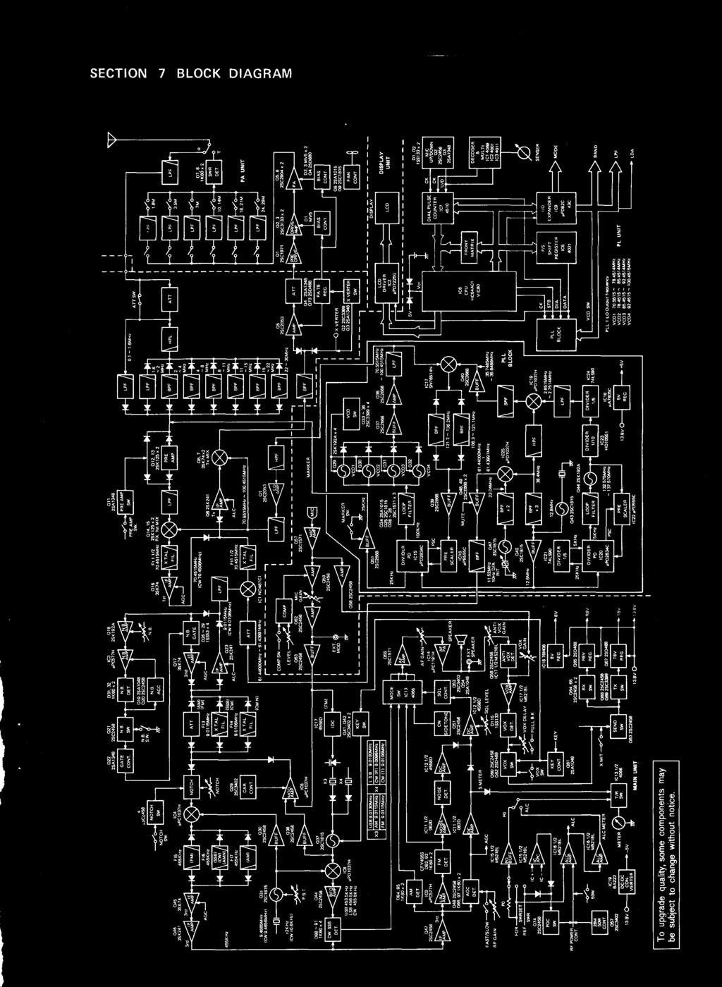
44 SECTION 7 BLOCK DIAGRAM
 a) < _c U a) CL E LO 7 < ch 5 E < O U- O co a) co a) 03.")
 a a a.")
 CC CC,LO Co (NI 5 5")
45 SECTION 8 INSIDE VIEWS 8-1 MAIN UNIT SIDE azza E E < C C < U o o c.) a) < _c U a) CL E LO 7 < ch 5 E < O U- O co a) co a) IL 8 2 IL N C 1.0 To Er_ LL m LL I LC) LO 'Cr _ N LL C.) a a a. E 2 0 C E 2 s, o X h ccj IC14 (AF Amp ) IF Q5 (Tral Transm itter Ba ndi cd3 E Co co To 8: co >> a, 0) CC CC,LO Co (NI 5 5 IC3 (No ise Amp ) IC1 (Secon d Mixer ) SSB, CW 9 MHz Filter

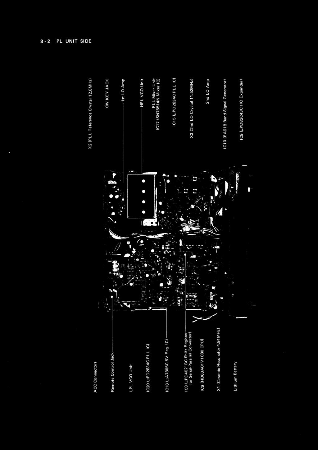
46 8-2 PL UNIT SIDE


.")
47 8-3 ADJUSTMENT LOCATIONS MAIN UNIT SIDE (Bottom View) *Receiver Audio Tone Adjustment n Bass Treble *CW Sidetone Volume Control n Minimum Maximum 1ii *TUNING CONTROL Brake Adjustment No cover removal is necessary for adjustments. I 50W 100W Power Control Switch *Receiver Audio Tone Adjustment *CW Sidetone Volume Control Space for Tone Encoder Unit (UT-30) for FM repeater operation. J23 for UT-30 Space for optional CW narrow filter (FL-32A or FL-63A). *Dim Adjustment See Side View diagram for adjustment hole.
 ON C138 (See section 6-11)")


48 (Side View) Dim Adjustment PL UNIT SIDE (Top View) ON C138 (See section 6-11) OFF Remote Control Terminal (J22) Scan Speed Adjustment P4 J P5 S2 Marker Switch (25kHz Marker) S1 Scan Timer Switch ON J23 for Electronic Keyer Open this jumper for a faster Scan.


49 8-4 DISASSEMBLY DIAGRAMS 1. PL UNIT is installed underneath the PA UNIT. The PA UNIT may be accessed by removing the top cover. 2. MAIN UNIT is installed on bottom side of the transceiver. The MAIN UNIT is visible when the bottom cover is removed. n PL UNIT SIDE TOP COVER! n BOTTOM COVER n MAIN UNIT SIDE
 AC POWER SUPPLY (13.8V 20A, Same height as IC-735) IC-PS30 AC POWER SUPPLY (13.")
 DESK MICROPHONE COMMUNICATION HEADPHONES MOBILE MOUNTING BRACKET n INTERNAL OPTIONS IC -E X243 UT-30 ELECTRONIC KEYER UNIT 88.")
50 SECTION 9 OPTIONAL UNITS n EXTERNAL OPTIONS AH -2 AT- 150 I C-AT500 IC-2K L PS-55 HF ALL BAND ANTENNA TUNER AUTOMATIC ANTENNA TUNER (Same height as IC-735) AUTOMATIC ANTENNA TUNER (500W Input power) LINEAR AMPLIFIER (500W output power) AC POWER SUPPLY (13.8V 20A, Same height as IC-735) IC-PS30 AC POWER SUPPLY (13.8V 25A) CT- 17 SP-7 IC-SP3 SM-10 SM-8 I C-SM6 HP-2 I C-MB5 CI-V LEVEL CONVERTER EXTERNAL SPEAKER (Same height as IC-735) EXTERNAL SPEAKER COMPRESSOR/GRAPHIC EQUALIZER DESK TOP MICROPHONE DESK MICROPHONE (Two microphone outputs, option) DESK MICROPHONE COMMUNICATION HEADPHONES MOBILE MOUNTING BRACKET n INTERNAL OPTIONS IC -E X243 UT-30 ELECTRONIC KEYER UNIT 88.5Hz TONE ENCODER (Frequency can be changed.) FL-32A CW NARROW FILTER (500Hz/-6dB) FL-63A CW NARROW FILTER (250Hz/-6dB)
 Printed in Japan")

51 Count on us! A-0649-N-a) Printed in Japan Copyright 1988 by!corn Inc.!corn Inc , Kamihigashi, Hirano-ku, Osaka 547, Japan
INSTALLATION AND CONNECTIONS
 INSTALLATION AND CONNECTIONS 3 Unpacking After unpacking, immediately report any damage to the delivering carrier or dealer. Keep the shipping cartons. For a description and a diagram of accessory equipment
QUICK REFERENCE GUIDE
 QUICK REFERENCE GUIDE Installation 1. Install a ground system for DC noise suppression and RFI suppression 2. Install your DC power supply 3. Install lightning protection. This will help protect more than
INSTALLATION AND CONNECTIONS Section 2
 STLLTION ND CONNECTIONS Section Unpacking - ntenna jumper cable connection - Selecting a location - Rack mounting handle attachment - Grounding -3 ntenna connection -3 CF (Compact Flash) memory card -3
The amazing evolution of the 706 series
 The amazing evolution of the 706 series The IC-706MKIIG carries on the 706 series tradition of base station performance and features in a mobile reg-sized package. Building on this legacy, frequency coverage
Icom IC-9100 HF/VHF/UHF transceiver
 263 Walsall Road, Great Wyrley, Walsall, WS6 6DL Established 1997. Open Monday - Friday 9am - 5pm and Saturday 9.30am - 4pm Tel: 01922 414 796 Fax: 01922 417829 Skype: radioworld_uk Icom IC-9100 HF/VHF/UHF
Elmer Session Hand Out for 3/3/11 de W6WTI. Some Common Controls Found On Amateur Radio Transceivers. (From ARRL web site tutorial)
") Elmer Session Hand Out for 3/3/11 de W6WTI Some Common Controls Found On Amateur Radio Transceivers. (From ARRL web site tutorial) The placement of the controls may vary from manufacturer to manufacturer
Elmer Session Hand Out for 3/3/11 de W6WTI Some Common Controls Found On Amateur Radio Transceivers. (From ARRL web site tutorial) The placement of the controls may vary from manufacturer to manufacturer
LnR Precision, Inc. 107 East Central Avenue, Asheboro, NC
 LD5 CW/SSB QRP Transceiver Quick guide manual Description: At the development base of the digital signal processing unit, an algorithm is embedded for IQ processing of the channels with phase suppression
CON NEX HP. OWNER'S MANUAL Full Channel AM/FM Amateur Mobile Transceiver TABLE OF CONTENTS TUNING THE ANTENNA FOR OPTIMUM S.W.R..
 TABLE OF CONTENTS PAGE SPECIFICATIONS... 2 INSTALLATION... 3 LOCATION... 3 CON NEX - 4300HP MOUNTING THE RADIO... 3 IGNITION NOISE INTERFERENCE... 4 ANTENNA... 4 TUNING THE ANTENNA FOR OPTIMUM S.W.R..
i78 INSTRUCTION MANUAL HF TRANSCEIVER
 INSTRUCTION MANUAL HF TRANSCEIVER i78 This device complies with Part 15 of the FCC rules. Operation is subject to the following two conditions: (1) This device may not cause harmful interference, and (2)
GRAND STRAND AMATEUR RADIO CLUB
 The GRAND STRAND AMATEUR RADIO CLUB (GSARC) Myrtle Beach SC is offering used amateur related equipment for sale. Written bids may be submitted to the GSARC up to Friday, November 23 rd, 2018. Only currently
Operation Manual. SlJPER ST AR Channel Mobile 5-Mode Transceiver -----~- --:.. KTSS200NXX ,, I
 Operation Manual!.,, SlJPER ST AR 2000 200 Channel Mobile 5-Mode Transceiver -----~- --:.. KTSS200NXX General Description l Frequency/Channel Chart The Super Star -2000 is a combination transmitter-receiver
INSTRUCTION MANUAL VHF/UHF ALL MODE TRANSCEIVER. i910h
 INSTRUCTION MANUAL VHF/UHF ALL MODE TRANSCEIVER i910h IMPORTANT EXPLICIT DEFINITIONS READ THIS INSTRUCTION MANUAL CAREFULLY before attempting to operate the transceiver. SAVE THIS INSTRUCTION MANUAL. This
LD5 CW/SSB QRP Transceiver SDR /DSP
 LD5 CW/SSB QRP Transceiver SDR /DSP Quick guide manual Description: At the development base of the digital signal processing unit, an algorithm is embedded for IQ processing of the channels with phase
DELUXE 18CHANNEL SSB/AM CB TRANSCEIVER OWNER'S GUIDE
 DELUXE 18CHANNEL SSB/AM CB TRANSCEIVER OWNER'S GUIDE General Description The Bush Ranger is a combination transmitter and receiver designed for use in the Australian 27 MHz Citizens radio service. It is
IC-F7000. Advanced selective call and ALE make HF communication easier than ever!
 Page 1 of 5 HF TRANSCEIVER IC-F7000 Advanced selective call and ALE make HF communication easier than ever! The IC-F7000 is an HF land mobile transceiver especially designed forlong distance communications.
KWM-2/2A Transceiver THE COLLINS KWM-2/2A TRANSCEIVER
 KWM-2/2A Transceiver Click the photo to see a larger photo Click "Back" button on browser to return Courtesy of Norm - WA3KEY THE COLLINS KWM-2/2A TRANSCEIVER Unmatched for versatility, dependability and
TABLE OF CONTENTS. Magnum International PO Box 445 Issaquah, WA 98027
 OPERATING MANUAL TABLE OF CONTENTS Limited Warranty... 2 Introduction... 3 Installation...3-4 Front Panel Controls and Functions...4-7 Other Features... 7 Specifications... 8 LIMITED WARRANTY Magnum International
OWNER'S MANUAL Channels All-Mode AM/FM/USB/LSB Built in Frequency Counter Mobile Transceiver with Roger Beep
 SUPER STAR 7QOODX OWNER'S MANUAL 3360 Channels All-Mode AM/FM/USB/LSB Built in Frequency Counter Mobile Transceiver with Roger Beep TABLE OF CONTENTS Page Specifications... 2 Installation Location... 4
DX AM FM SSB CW PA Amateur Base Station Transceiver OWNER S MANUAL RX / TX 2 4 POWER NF CHANNEL MODE RF POWER OFF CAL OFF OFF CALIBRATE
 1 2 3 6 4050 ULA 6070 TI 80 90 100 9 DX 2517 2517 RX / TX 0 2 4 SWR WATTS SET 81012 22 1 010 3 2030 5 MOD 7 ON dbover 9 SIGNAL +20 +40+60 PA FM AM USB LSB CW POWER ON SWR NB / ANL R.BEEP +10KHz NF CHANNEL
18-CHANNEL MOBILE CB TRANSCEIVER MODEL CB-845
 18-CHANNEL MOBILE CB TRANSCEIVER MODEL CB-845 INSTRUCTION HANDBOOK RAll JEFFERSOn CITIZEN BAND RADIO MESSAGE TO THE OWNER CONGRATULATIONS! As the new owner of Ray Jefferson Model CB-845 CB Mobile Transceiver,
DX 73V OWNER S MANUAL FULL FEATURED AM/FM MOBILE TRANSCEIVER. WARRANTY This radio is covered by a two year limited parts and labor warranty.
 WARRANTY This radio is covered by a two year limited parts and labor warranty. Limited means that we will repair problems caused by factory defects or normal use at no charge. Before returning a radio
SPECS FEATURES SUPPLIED ACCESSORIES. HF All Band Transceiver
 718 HF All Band Transceiver RX 0.030-29.999999MHz* TX 1.800-1.999999 MHz** 3.500-3.999999 MHz** 7.000-7.300000 MHz 10.100-10.150000 MHz 14.000-14.350000 MHz 18.068-18.168000 MHz 21.000-21.450000 MHz 24.890-24.990000
SUBELEMENT T4. Amateur radio practices and station set up. 2 Exam Questions - 2 Groups
 SUBELEMENT T4 Amateur radio practices and station set up 2 Exam Questions - 2 Groups 1 T4A Station setup: connecting microphones; reducing unwanted emissions; power source; connecting a computer; RF grounding;
INSTRUCTION MANUAL HF ALL BAND TRANSCEIVER. i718
 INSTRUCTION MANUAL HF ALL BAND TRANSCEIVER i718 IMPORTANT EXPLICIT DEFINITIONS READ ALL INSTRUCTIONS carefully and completely before using the transceiver. SAVE THIS INSTRUCTION MANUAL This instruction
hallicrafters PERFORMANCE SPECIFICATIONS MODEL: SR-2000 LATEST REVISION: 18 JAN 66 Code ident # Specification #
 hallicrafters PERFORMANCE SPECIFICATIONS MODEL: SR-2000 LATEST REVISION: 18 JAN 66 Code ident # 26916 Specification # 093-002154 I. GENERAL A. Power input 117V 50-60 cycles from a source capable of delivering
DX 33HML. Full Channel AM/FM Mobile Transceiver OWNER S MANUAL. Printed In Malaysia AT H PD000802
 DX 33HML Full Channel AM/FM Mobile Transceiver Printed In Malaysia AT3601014H PD000802 OWNER S MANUAL TABLE OF CONTENTS Page Specification.................................... 2 Installation Location.....................................
VvV MODEL-309 OWNER'S MANUAL. 40 channel CB Transceiver. Professional Quality And Performance Standards Advanced Circuitry With PLL Synthesis
 VvV MODEL-309 OWNER'S MANUAL 40 channel CB Transceiver Professional Quality And Performance Standards Advanced Circuitry With PLL Synthesis GENERAL INSTRUCTIONS Your model is an all solid-state SSB/AM
INSTRUCTION MANUAL. HF/50 MHz TRANSCEIVER. i7200
 INSTRUCTION MANUAL HF/ MHz TRANSCEIVER i IMPORTANT R E A D T H I S I N S T RU C T I O N M A N UA L CAREFULLY before attempting to operate the transceiver SAVE THIS INSTRUCTION MANUAL This manual contains
AM/FM 10 METER MOBILE AMATEUR TRANSCEIVER OPERATING MANUAL
 AM/FM 10 METER MOBILE AMATEUR TRANSCEIVER OPERATING MANUAL INTRODUCTION Congratulations on your purchase of a Magnum S-6 AM/FM 10 meter transceiver. Your Magnum S-6 is designed to provide years of enjoyment
Pushing performance to the pinnacle
 Pushing performance to the pinnacle The latest DSP technologies developed for the IC-7800/7700 plus over 45 years of analog circuit expertise give the IC-7600 the performance advantage. The flagship's
Midland 248XL I NSTRUCTION GUI DE
 Midland 248XL I NSTRUCTION GUI DE INDEX Introduction...2 Function and location of the controls...3 Installation...7 Power supply...7 Installing an antenna...7 How to use your Midland 248XL...8 Frequency
TOA NEW 900 SERIES MIXER PREAMPLIFIER M-900A
 Operation Instruction Manual TOA NEW 900 SERIES MIXER PREAMPLIFIER M-900A Features General Description 1 6-channel mixer preamplifier 2 Wide frequency response; 20 20,000Hz, ±1dB 3 Low distortion and noise
INSTRUCTION MANUAL. HF/50 MHz TRANSCEIVER. i7410
 INSTRUCTION MANUAL HF/0 MHz TRANSCEIVER i0 i FOREWORD Thank you for making the IC-0 your radio of choice. We hope you agree with Icom s philosophy of technology first. Many hours of research and development
Vectronics VC-300D DIGITAL BARGRAPH ANTENNA TUNER
 Vectronics VC-300D DIGITAL BARGRAPH ANTENNA TUNER FEATURES The Vectronics VC-300D Antenna Tuner optimizes the performance of your antenna and transmitter, receiver, or transceiver by providing adjustable
Technician License Course Chapter 5. Lesson Plan Module 11 Transmitters, Receivers and Transceivers
 Technician License Course Chapter 5 Lesson Plan Module 11 Transmitters, Receivers and Transceivers Generalized Transceiver Categories Mobile Single Band Dual Band All Band Multimode Handheld (HT) VHF/UHF
Frequency Coverage MHz RF Power Output 30W SSB / 9W AM/ 30W FM Dual Finals on Heat Sink Modes AM, FM, USB, LSB Microprocessor
 MAGNUM M-257 30W AM/ /FM/SSB 10--11 Meterr Mobile Trranscei ivverr n Prri iiccee: : US$ 250..00 eexx ssttoocckk JJaakkaarrttaa (Arrrri ( iivvi iinngg 2 d weeeekk iinn i Maarrcchh) ) SPECIFICATIONS Frequency
OPTIMA MK3 OWNERS MANUAL & USER GUIDE Mhz 50W All Mode HF Mobile Transceiver. (November 2012 production)
") OPTIMA MK3 OWNERS MANUAL & USER GUIDE 24.500 29.999 Mhz 50W All Mode HF Mobile Transceiver (November 2012 production) REV 1.8 Copyright November 2012 by YeticomNZ. All rights reserved. Downloaded from
OPTIMA MK3 OWNERS MANUAL & USER GUIDE 24.500 29.999 Mhz 50W All Mode HF Mobile Transceiver (November 2012 production) REV 1.8 Copyright November 2012 by YeticomNZ. All rights reserved. Downloaded from
HF/50MHz TRANSCEIVER
 HF/50MHz TRANSCEIVER D isplay Pushing performance to the pinnacle The latest DSP technologies developed for the flagship models plus many decades of analog circuit expertise give the the performance advantage.
THE TRANSCEIVER Instruction Manual
 THE TRANSCEIVER i7800 Instruction Manual A-6328H-1EX-q Printed in Japan 2004 Icom Inc. FOREWORD Congratulations! You are the owner of the world s most advanced amateur HF/50 MHz transceiver IC-7800. The
Barrett 950 HF transceiver specifications Using measurement methods described in European Telecommunication Standard
 Barrett 950 HF transceiver specifications Using measurement methods described in European Telecommunication Standard 300 373. General Specifications Equipment Standards Transmit frequency range Receive
TOA 500 SERIES MIXER POWER AMPLIFIER
 TOA 500 SERIES MIXER POWER AMPLIFIER Operation Instruction Manual A-503A A-506A A-512A Features General Description 1. High quality design and construction. 2. Full frequency response: 50-15,000Hz, ±3dB.
DX 33HP. 10 Meter Amateur Mobile Transceiver OWNER S MANUAL. Download this Manual Free of Charge at
 DX 33HP SIG 1 3 TX PWR 5 7 9+30dB POWER HI NB/ANL MED LO HI LO BAND ECHO RX/TX VOL SQ MIC RF FM PA AM D/A E/B F/C ECHO TIME BAND 10 Meter Amateur Mobile Transceiver Download this Manual Free of Charge
Installation... 3 Installing The Radio... 3 Ignition Noise Interference... 4 Antenna... 4 External Speaker... 4 Public Address...
 TABLE OF CONTENTS CHAPTER 1 Specifications.............................................. 2 PAGE BIG RIG SERIES S 1 MOD PW R 20 0 3 SW R 40 1 5 5 60 1.5 7 10 2 9 20 80 3 30 +20 40 50 +40 100% MAX db +60
TS-590SG HF/ 50MHz All-Mode TRANSCEIVER_
 New Product Release Information Oct 2014 TS-590SG HF/ 50MHz All-Mode TRANSCEIVER_ Kenwood introduces Updated to new G version new HF/50MHz All-Mode Transceiver Four years ago we launched our best-selling
LBI-31564A. Mobile Communications. DELTA - SX MHz RADIO COMBINATIONS (NEGATIVE GROUND ONLY) Maintenance Manual
 Maintenance Manual") A Mobile Communications DELTA - SX 136-174 MHz RADIO COMBINATIONS (NEGATIVE GROUND ONLY) Maintenance Manual TABLE OF CONTENTS MILITARY AND SYSTEM SPECIFICATIONS................................. 2-3 COMBINATION
A Mobile Communications DELTA - SX 136-174 MHz RADIO COMBINATIONS (NEGATIVE GROUND ONLY) Maintenance Manual TABLE OF CONTENTS MILITARY AND SYSTEM SPECIFICATIONS................................. 2-3 COMBINATION
DX 29HP. 10 Meter Amateur Mobile Transceiver OWNER S MANUAL PRINTED IN MALAYSIA PN:A412308CNA
 DX 29HP 10 Meter Amateur Mobile Transceiver OWNER S MANUAL PRINTED IN MALAYSIA PN:A412308CNA TABLE OF CONTENTS Page Specification.................................... 2 Installation Location.....................................
DX 66V OWNER S MANUAL. Full Channel AM/FM Mobile Transceiver Built in Frequency Counter with Roger Beep
 WARRANTY This radio is covered by a two year limited parts and labor warranty. Limited means that we will repair problems caused by factory defects or normal use at no charge. Before returning a radio
INSTRUCTION MANUAL. HF/50 MHz ALL MODE TRANSCEIVER
 INSTRUCTION MANUAL HF/50 MHz ALL MODE TRANSCEIVER This device complies with Part 5 of the FCC rules. Operation is subject to the following two conditions: () This device may not cause harmful interference,
FT-897 Alignment. Local Oscillator Adjustment. PLL Adjustment
 FT-897 Local Oscillator Adjustment Reference Frequency Adjustment a. Connect a frequency counter to TP1032. b. Adjust the trimmer capacitor (TC5001) for 67.875000MHz ±5Hz on the frequency counter. c. Connect
Using measurement methods described in Australian/New Zealand Standard AS/NZS 4770:2000
 Barrett 2050 HF transceiver Using measurement methods described in Australian/New Zealand Standard AS/NZS 4770:2000 General Specifications Equipment Standards Transmit frequency range Receive frequency
AM/FM/SSB/CW 12 & 10 METER MOBILE AMATEUR TRANSCEIVER OWNER S MANUAL
 AM/FM/SSB/CW 12 & 10 METER MOBILE AMATEUR TRANSCEIVER OWNER S MANUAL TABLE OF CONTENTS Warranty...2 Introduction...3 Installation... 4-5 Front Panel Controls... 6-8 Microphone...8 Menu Settings... 9-11
HF TRANSCEIVER V1.0. Copyright 2014, XIEGU, Inc. All Rights Reserved
 HF TRANSCEIVER V1.0 Copyright 2014, XIEGU, Inc. All Rights Reserved Table of Contents I. Introduction equipment Second, the device description Third, the operating instructions Four, advanced menu settings
Second Hand Yaesu FTDX5000MP HF base station transceiver
 263 Walsall Road, Great Wyrley, Walsall, WS6 6DL Established 1997. Open Monday - Friday 9am - 5pm and Saturday 9.30am - 4pm Tel: 01922 414 796 Fax: 01922 417829 Skype: radioworld_uk Second Hand Yaesu FTDX5000MP
?COM IC-725. loom Inc. INSTRUCTION MANUAL HF ALL BAND TRANSCEIVER
 ?COM INSTRUCTION MANUAL HF ALL BAND TRANSCEIVER IC-725 loom Inc. CAUTIONS INTRODUCTION (1) Before using the IC-725, read all instructions carefully and completely. (2) SAVE THIS INSTRUCTION MANUAL - This
HR MHZ AM-FM AMATEUR RADIO HF TRANSCEIVER OWNER'S MANUAL. Content of the packaging
 HR-2800 28 MHZ AM-FM AMATEUR RADIO HF TRANSCEIVER OWNER'S MANUAL NOTICE! It is recommended to carefully read this owner s manual before using the product. This will also help to prevent illegal use of
AE 497 W (25-30 W-Version)
") User Manual AE 497 W (25-30 W-Version) 10-Meter Amateur Radio Base Station Legal notes and general information This amateur radio base station complies to the minimum requirements of the EU directives
User Manual AE 497 W (25-30 W-Version) 10-Meter Amateur Radio Base Station Legal notes and general information This amateur radio base station complies to the minimum requirements of the EU directives
Technician License Course Chapter 3 Types of Radios and Radio Circuits. Module 7
 Technician License Course Chapter 3 Types of Radios and Radio Circuits Module 7 Radio Block Diagrams Radio Circuits can be shown as functional blocks connected together. Knowing the description of common
User Manual. Specifications...3. Control and Operation Microphone...8. Installation...9. Installation of Main Unit...9
 Contents Specifications...3 Control and Operation...4-7 Microphone...8 Installation...9 Installation of Main Unit...9 Antenna Installation...9 Operational test...9 Frequency Bands Table...10 Frequency
OM1006 Solid State 50 MHz Power Amplifier
 Instruction Manual OM1006 Solid State 50 MHz Power Amplifier OM POWER, s. r. o. 930 30 Báč 126 SLOVAKIA E-mail: om-power@om-power.com TABLE OF CONTENTS 1. GENERAL INFORMATION 1.1. Introduction.. 4 1.2.
4W MOBILE CB TRANSCEIVER INSTRUCTION MANUAL
 4W MOBILE CB TRANSCEIVER INSTRUCTION MANUAL www.ttikorea.co.kr CONTENTS 1. Introduction 2. Supplied Accessories 3. Installation 4. Transceiver Controls and Functions 1) Microphone Jack 2) LCD Display 3)
RU210. Dual Multi-UHF Wireless System. Item ref: UK, UK User Manual. Version 1.0
 RU210 Dual Multi-UHF Wireless System Item ref: 171.970UK, 171.971UK User Manual Version 1.0 Caution: Please read this manual carefully before operating Damage caused by misuse is not covered by the warranty
RCI-6300F25/150. Owner's Manual. AM/FM Amateur Transceiver With Built-in Frequency Counter. Table of Contents. Downloaded from
 Table of Contents RCI-6300F25/150 AM/FM Amateur Transceiver With Built-in Frequency Counter PAGE Chapter 1 Specifications...... 2 Chapter 2 Installation...... 3 Installing the Radio... 3 Ignition Noise
Instruction Kit MIXER AMPLIFIER GT 60C GT 125C. GROMMES-PRECISION SINCE-46
 Instruction Kit GT 60C GT 125C MIXER AMPLIFIER GROMMES-PRECISION 1-800-SINCE-46 www.grommesprecision.com Thank you for purchasing from Grommes~Precision! Grommes~Precision and its commercial audio division,
WARNING WELCOME TO USE RESET
 WARNING Please install the antenna (connect to the location B on the back panel of the radio) and set the SWR (Standing Wave Ratio) before transmitting. Failure to do so may result in destruction of the
Technician Licensing Class. Lesson 4. presented by the Arlington Radio Public Service Club Arlington County, Virginia
 Technician Licensing Class Lesson 4 presented by the Arlington Radio Public Service Club Arlington County, Virginia 1 Quiz Sub elements T6 & T7 2 Good Engineering Practice Sub element T8 3 A Basic Station
SUPERSTAR TABLE OF CONTENTS AM/FM/USB/LSB/CW AMATEUR MOBILE TRANSCEIVER WITH BUILT-IN FREQUENCY COUNTER OWNER S MANUAL
 SUPERSTAR TABLE OF CONTENTS AM/FM/USB/LSB/CW AMATEUR MOBILE TRANSCEIVER WITH BUILT-IN FREQUENCY COUNTER PAGE CHAPTER 1 Specifications............................................... 2 CHAPTER 2 Installation.................................................
DX 99V OWNER S MANUAL. Full Channel AM/FM/SSB Mobile Built in Frequency Counter with Roger Beep
 WARRANTY This radio is covered by a two year limited parts and labor warranty. Limited means that we will repair problems caused by factory defects or normal use at no charge. Before returning a radio
TOA NEW 900 SERIES MIXER POWER AMPLIFIER A-901A. General Description. TOA Corporation. Operation Instruction Manual
 Operation Instruction Manual TOA NEW 900 SERIES MIXER POWER AMPLIFIER A-901A Features 1 3-channel mixer power amplifier 2 Wide frequency response; 20 20,000 Hz, ±1dB 3 Low distortion and noise level 4
Zeon PDF Driver Trial
 401 W. 35th Street, Suite B National City, CA 91950 (800)446-5778. FAX( 619)426-3788 Email : rci@rangerusa.com http : //www.rangerusa.com Printed In Malaysia AT6960A11A PD000619 TR-936 SOLID STATE CITIZENS
mat-180h HF-SSB Automatic Antenna Tuner Instruction Manual Version V1.0
 INTRODUCTION mat-180h HF-SSB Automatic Antenna Tuner Instruction Manual Version V1.0 The mat-180h is an automatic tuner intended for use with modern Icom transceivers. It works with any Icom transceiver
Downloaded from
 Owner s Manual AM/FM 40 CHANNEL & TONE SQUELCH CITIZENS BAND TRANSCEIVER Downloaded from www.cbradio.nl Characteristics of C-Five 1. Improved audio sensitivity by adopting audio compressing and decompressing
TOA 900 SERIES POWER AMPLIFIER P-924A
 Operation Instruction Manual TOA 900 SERIES POWER AMPLIFIER P-924A Features General Descriptions 1 Wide frequency response; 20 20,000 Hz, ±1dB 2 Low distortion and noise level 3 Excellent output regulation
Zeon PDF Driver Trial
 401 W. 35th Street, Suite B National City, CA 91950 (800)446-5778. FAX( 619)426-3788 Email : rci@rangerusa.com http : //www.rangerusa.com Printed In Malaysia AT6960A11B PD000619 TR-966 SOLID STATE CITIZENS
INSTRUCTION MANUAL. HF/VHF ALL MODE TRANSCEIVER i746pro
 INSTRUCTION MANUAL HF/VHF ALL MODE TRANSCEIVER i746pro This device complies with Part 15 of the FCC rules. Operation is subject to the following two conditions: (1) This device may not cause harmful interference,
MODEL FS-4 INSTRUCTION MANUAL R.L. DRAKE COMPANY, MIAMISBURG, OHIO, U.S.A.
 MODEL FS-4 F R E Q U E N C Y S Y N T H E S I Z E R INSTRUCTION MANUAL R.L. DRAKE COMPANY, MIAMISBURG, OHIO, U.S.A. LIMITED WARRANTY R. L. DRAKE COMPANY warrants to the original purchaser that this product
Lesson 9: Base Stations
 Lesson 9: Base Stations Preparation for Amateur Radio Technician Class Exam Topics Home Stations Basic Station Layout RTTY and Data Communications Station Accessories Wavelengths Feed Lines Impedance-matching
Transceiver selection and Specs.
 Transceiver selection and Specs. Transceivers 1956-2018 From TUBES to SDR Covers 20-10 meters in 100Khz segments, 10 available, crystal needed for each. Plug in crystal holder. 100 Watts output, final
Synthesized Base Station Transmitter
 BST-25 OPERATOR S MANUAL (216 MHz) Synthesized Base Station Transmitter 357 West 2700 South Salt Lake City, Utah 84115 Phone: (800) 496-3463 Fax: (801) 484-6906 http://www.comtek.com INTRODUCTION BST-25
Module 8 Theory. dbs AM Detector Ring Modulator Receiver Chain. Functional Blocks Parameters. IRTS Region 4
 Module 8 Theory dbs AM Detector Ring Modulator Receiver Chain Functional Blocks Parameters Decibel (db) The term db or decibel is a relative unit of measurement used frequently in electronic communications
DX 93T OWNER S MANUAL. 10 Meter Amateur Mobile Transceiver With Built-in Frequency Counter & StarLite Face Plate TABLE OF CONTENTS CHAPTER 1 CHAPTER 2
 PAGE CHAPTER 1 Specifications.............................................. 2 Twin Turbine S 1 PW R 3 20 0 SW R 40 1 5 5 60 1.5 7 10 2 9 20 80 3 30 +20 40 50 DX 93T +40 100% MAX db +60 DX 93T B A SW R
i. AM. Radio Transmitter Installation and Operation Easy to follow instructions on how to program and use your Model 5.0 i. AM.
 i. AM. Radio Transmitter Installation and Operation Easy to follow instructions on how to program and use your Model 5.0 i. AM. Radio Transmitter Contents Quick Start...3 Front and Rear Panel Controls...5
MFJ-752C SIGNAL ENHANCER II
 MFJ-752C SIGNAL ENHANCER II INTRODUCTION The improved MFJ-752C SIGNAL ENHANCER II is comprised of two tunable audio filtering systems designed to clarity and remove interfering signals from both voice
KENWOOD SKY COMMAND SYSTEM
 KENWOOD SKY COMMAND SYSTEM Operation Manual KENWOOD COMMINICATIONS CORPORATION KENWOOD COMMUNICATIONS CORPORATION This operation manual is used for the KENWOOD SKY COMMAND SYSTEM (hereinafter referred
VECTRONICS HFT-1500 Digital Bargraph Antenna Tuner
 Table of Contents FEATURES... 1 SPECIFICATIONS... 1 FRONT PANEL INDICATORS AND CONTROLS... 1 CONTROLS... 1 REAR PANEL CONNECTORS... 1 OTHER... 2 CONTOLS / CONNECTORS... 2 FRONT PANEL FUNCTIONS... 2 REAR
.TABLE OF CONTENTS Introduction... 2 Installation Front Panel Controls and Functions Other Features... 8 Specifications...
 .TABLE OF CONTENTS Introduction... 2 Installation... 3-4 Front Panel Controls and Functions... 4-8 Other Features... 8 Specifications... 10 European Warranty Conditions Your distributor, where You have
VC-300D VECTRONICS R. Digital Bar Graph Antenna Tuner. Owner's Manual. CAUTION: Read All Instructions Before Operating Equipment!
 VC-300D Digital Bar Graph Antenna Tuner CAUTION: Read All Instructions Before Operating Equipment! VECTRONICS R... the finest amateur radio products made 300 Industrial Park Road Starkville, MS 39759 (662)
INSTRUCTION MANUAL. VHF dpmr REPEATER. ifr5000. UHF dpmr REPEATER. ifr6000
 INSTRUCTION MANUAL VHF dpmr REPEATER ifr5000 UHF dpmr REPEATER ifr6000 FORWARD Thank you for purchasing this Icom repeater. The IC- FR5000/IC-FR6000 vhf/uhf dpmr repeaters is designed and built with Icom
Downloaded from
 TABLE OF CONTENTS Installation... 2 Location... 2 Mounting the Connection... 2 Ignition Noise Interference... 2 Antenna... 2 Tuning the Antenna for Optimum SWR... 3 External Speaker... 4 Replacing fuse...
Synthesized Base Station Transmitter
 BST-75 OPERATOR S MANUAL (72-76 MHz) Synthesized Base Station Transmitter 357 West 2700 South Salt Lake City, Utah 84115 Phone: (800) 496-3463 Fax: (801) 484-6906 www.comtek.com TABLE OF CONTENTS Introduction...
Operating Station Equipment
 Amateur Radio License Class Operating Station Equipment Presented by Steve Gallafent October 3, 2007 Operating Station Equipment Modulation Modulation is the process of adding information to a radio signal
HF Receivers, Part 2
 HF Receivers, Part 2 Superhet building blocks: AM, SSB/CW, FM receivers Adam Farson VA7OJ View an excellent tutorial on receivers NSARC HF Operators HF Receivers 2 1 The RF Amplifier (Preamp)! Typical
Introduction. CONT N NT S Cautions Before Operation 2. Major Features 3. Operating Controls and Functions 4. How to use Keyboard 6
 Introduction Congratulations! Now you are the owner of the most advanced state of the art VHF FM transceiver available today. Please read this manual carefully before attempting to operate your PCS 6000
Single Channel Radio Mic System USER MANUAL. WMU-116-H (Hand Held) WMU-116-B (Belt Pack) Single Channel Radio Mic System
 WMU-116-B (Belt Pack) Single Channel Radio Mic System") Single Channel Radio Mic System USER MANUAL WMU-116-H (Hand Held) WMU-116-B (Belt Pack) Single Channel Radio Mic System Welcome Thank you for choosing Hill Audio for your sound system. To make sure that
Single Channel Radio Mic System USER MANUAL WMU-116-H (Hand Held) WMU-116-B (Belt Pack) Single Channel Radio Mic System Welcome Thank you for choosing Hill Audio for your sound system. To make sure that
music Miniature instruments wireless system Instruction Manual
 Miniature music instruments wireless system Instruction Manual 1. Important Caution Always make all connections before plugging the unit into an AC power outlet. Do not leave the devices in a place with
USER'S MANUAL UHF BAND
 USER'S MANUAL I UHF BAND MICROPHONE SYSTEM I 1440-8120-01 NOTE. HmmHmmmJ i... 1 FCC Statement MICROPHONE SYSTEM Table of Contents 1. Introduction......... 1 2. Safety... 1 3. Environment... 1 4. Wireless
HF SIGNALS ΜBITX. The QRP HF General Coverage Transceiver you can build. Buy Now Circuit Description Wireup Tune Up Help and Support BITX Hacks
 Page 1 of 5 HF SIGNALS ΜBITX The QRP HF General Coverage Transceiver you can build Buy Now Circuit Description Wireup Tune Up Help and Support BITX Hacks ($109 USD) Page 2 of 5 The µbitx is a general coverage
VECTRONICS. VC-300DLP Antenna Tuner
 VECTRONICS VC-300DLP Antenna Tuner FEATURES The Vectronics VC-300DLP Antenna Tuner optimizes the performance of your antenna and transmitter, receiver, or transceiver by providing adjustable impedance
PLL SYNTHESIZED RECEIVER FM STEREO / MW / LW / SW-SSB / AIR BAND OPERATION MANUAL TECSUN PL-660. Shortwave BW
 PL-660 PLL SYNTHESIZED RECEIVER FM STEREO / MW / LW / SW-SSB / AIR BAND OPERATION MANUAL TECSUN Shortwave BW FAST khz SYNC USB PL-660 AM SYNCHRONOUS DETECTOR FM STEREO/LW/MW/SW-SSB/AIR PLL SYNTHESIZED
Digital HF Receiver WJ-8723
 Developmental Specification WATKINS-JOHNSON April 1996 Digital HF Receiver WJ-8723 Description The WJ-8723 is a fully synthesized, general-purpose HF receiver that monitors RF communications from 5 khz
1. Your new Eagle 599 3
 Table of Contents 1. Your new Eagle 599 3 1.1. Unpacking Eagle 599 3 1.2. About this Manual 3 1.3. Accessory package 3 1.4. Connection to Antenna & Power Supply 4 1.5. A word about grounding 4 1.6. Philosophy