MODEL FS-4 INSTRUCTION MANUAL R.L. DRAKE COMPANY, MIAMISBURG, OHIO, U.S.A.
|
|
|
- Virgil Gibbs
- 5 years ago
- Views:
Transcription

1 MODEL FS-4 F R E Q U E N C Y S Y N T H E S I Z E R INSTRUCTION MANUAL R.L. DRAKE COMPANY, MIAMISBURG, OHIO, U.S.A.
2 LIMITED WARRANTY R. L. DRAKE COMPANY warrants to the original purchaser that this product shall be free from defects in material (except tubes and RF output transistors) or workmanship for ninety (90) days from the date of originai purchase. During the warranty period the R. L. DRAKE COMPANY or an authorized Drake service facility will provide free of charge both parts (except tubes and RF output transistors) and labor necessary to correct defects in material or workmanship. To obtain such warranty service, the original purchaser must: (1) Complete and send in the Warranty Registration Card. (2) Notify R. L. DRAKE COMPANY or its nearest authorized service facility, as soon as possible after discovery of a possible defect, (a) The model number and serial number, if any; (b) The identlty of the seller and the approximate date of purchase; (c) A detailed description of the problem, including details on the electrical connection to associated equipment and the list of such equipment. (3) Deliver the product to the R. L. DRAKE COMPANY or the nearest authorized service facility, or ship the same in its original container or equivalent, fully insured and shipping charges prepaid. Correct maintenance, repair and use are important to obtain proper performance from this product. Therefore, carefully read the Instruction Manual. This warranty does not apply to any defect that R. L. DRAKE COMPANY determines is due to: (1) Improper maintenance or repair, including the installation of parts or accessories that do not conform to the quality and specifications of the original parts. (2) Misuse, abuse, neglect or Improper installation. (3) Accidental or intentional damage. All implied warranties, if any, terminate ninety (90) days from the date of the original purchase. The foregoing costitutes R. L. DRAKE COMPANY'S entire obligation with respect to this product, and the original purchaser and any user or owner shail have no other remedy and no claim for incidental or consequential damages. Some states do not allow limitations on how long an implied warranty lasts or do not allow the exclusion or limitation of incidental or consequential damages, so the above limitation and exclusion may not apply to you. This warranty gives specific legal rights and you may also have other rights which vary from state to state. R. L. DRAKE COMPANY 540 Richard Street Miamisburg, Ohio 45342
3 1-1. GENERAL DESCRIPTION. CHAPTER I INTRODUCTION The FS-4 is a frequency synthesizer developed for use with the Drake Company 4 line equipment. (R-4 series, T-4X series and SPR-4.) The FS-4 plugs into an unused auxiliary crystal socket in the rear of the receiver or transmitter, and will supply the various injection signals to the equipment and allows continuous coverage without utilizing the accessory crystals. The frequency readout on the FS-4 displays the received frequency band, and to this is added the frequency readout of the receiver "PTO" to obtain the correct received frequency. The FS-4 supplies ali the crystal oscillator injection signals for the R-4 series and T-4X series in 0.5 MHz steps from 11.1 through 40.6 MHz, and the readout is direct. An accessory kit is available to provide proper injection signals for the SPR-4 receiver. The FS-4 can be used with the 2-C type receiver over the frequency range of 7 to 30 MHz. When used with the 2-C receiver, the FS-4 frequency read-out is not direct, and a correction factor of 7 Mhz must be added to the FS-4 readout to obtain the correct operating frequency. A special accessory kit is necessary to modify the FS-4 for use with the 2-C receiver MANUAL COVERAGE. This manual is presented in 5 chapters and is arranged for the convenience of the operator and service technician as follows: CHAPTER I CHAPTER II CHAPTER III CHAPTER IV CHAPTER V Introduction. (Self explanatory.) Installation. Describes the procedures to be followed prior to operation. Operation. Illustrates and describes front panel controls, and describes operation with Drake receiver/transmitter equipment. Theory of Operation. Describes all circuits and networks. Maintenance. Provides maintenance and alignment instructions.
4 CHAPTER II INSTALLATION 2-1. UNPACKING. Carefully remove the FS-4 from the shipping carton and examine it for evidence of damage. If any damage is discovered, immediately notify the transportation company that delivered the unit. NOTE Fill out the enclosed registration card and return it to the factory immediately to insure registration and validation of the warranty LOCATION. The FS-4 is supplied with a cable approximately 20 inches long that piugs into the accessory crystal socket of the receiver/transmitter. This length aliows the user to piace the FS-4 on either side of the receiver/transmitter. Placing the FS-4 on top of the transmitter is not recommended, due to heat generated within the transmitter, and the FS-4 will block the air flow POWER REQUIREMENTS. The FS-4 is shipped from the factory wired for 120 VAC, 50/60 Hz, operation uniess otherwise specified. To operate on 240 VAC make the proper connections at the transformer on the parent board as illustrated in figure FUSE. The power line is fused for 120 VAC operation with a 3AG Type 1/8 A, Slo-Blo. For 240 VAC operation use a 3AG Type 1/16 A, or equivalent.
5
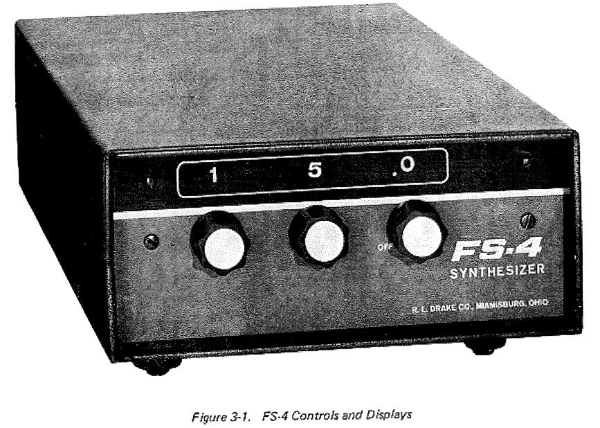
6 CHAPTER III OPERATION 3-1. CONTROLS AND DISPLAYS. All controls and displays necessary for the operation of the FS-4 are located on the front panel. The three knobs switch the frequency range in.5 MHz steps and provide direct frequency display in MHz at the readout directly above each knob. These knobs switch the frequency in steps of 10 MHz, 1 MHz, and 0.5 MHz from left to right. The 0.5 MHz knob also turns the FS-4 on and off. Refer to figure INJECTION CABLE. The injection cable supplied is used to connect the FS-4 to an unused accessory crystal socket of the receiver or transmitter. Attach the ground lug to the chassis at the accessory crystal socket and insert the center pin into the selected accessory crystal socket. The receiver or transmitter will operate best when the center conductor is connected to the emitter of the crystal oscillator. This can be determined by noting the S meter reading or power output readout when the injection cable is plugged into each socket of the accessory crystal socket BAND SELECT. When using the FS-4 to control a receiver or transmitter, the receiver/transmitter must be placed in the proper band as you would in normal use, and the crystal switch must be placed in the position corresponding with the position selected to plug in the FS-4. The RF tune (preselector) of the receiver/transmitter must be tuned the same as in normal use PRESELECTOR SETTING. A stick-on-decal has been supplied for convenience in locating the positioning of the RF tune (preselector). This may be applied to the receiver/transmitter front panel by removing the knob and aligning the decal on the front panel and firmly rubbing it on.
7
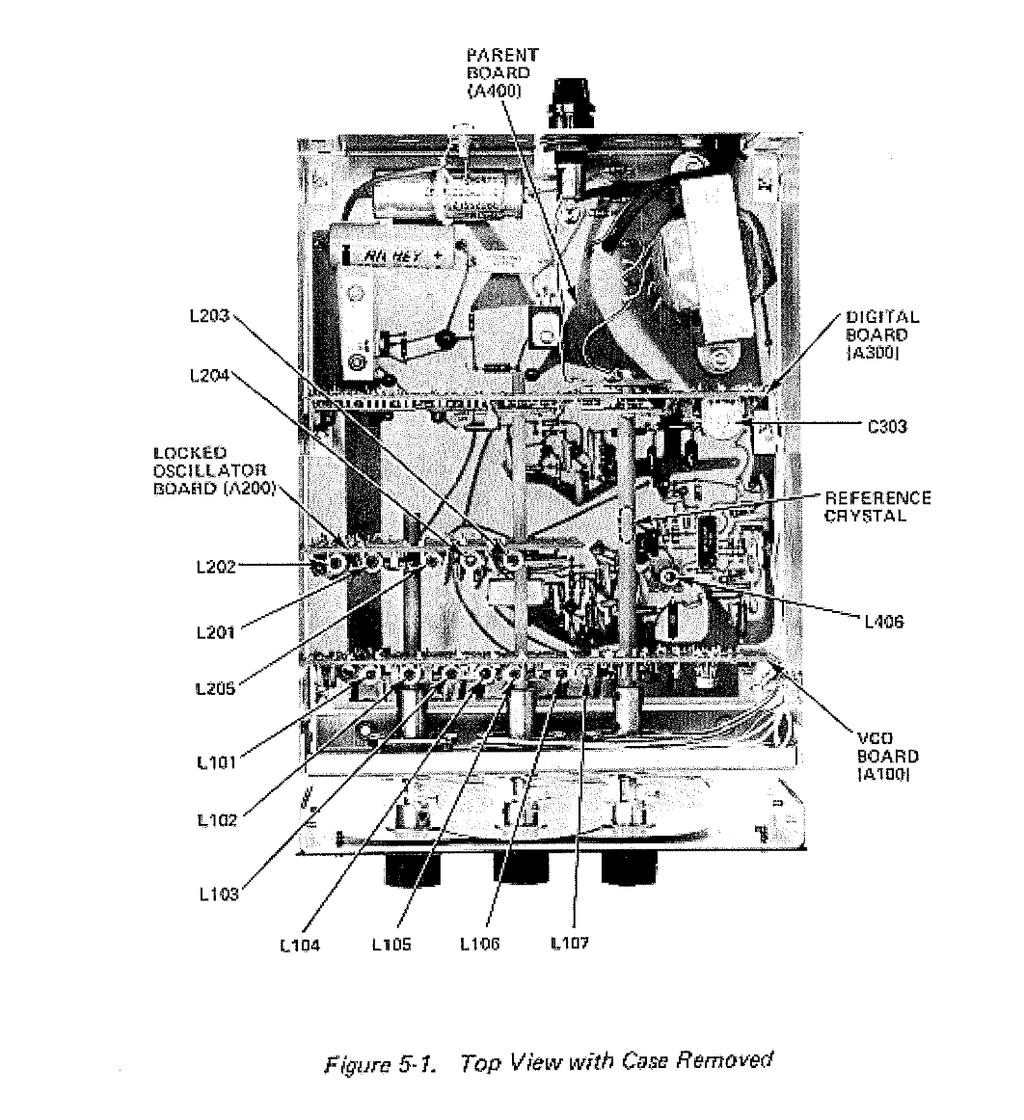
8 Caution must be used on proper use of the FS-4 when used with transmitters. Consult RF Tune calibration charts in the manual of the T-4X series TUNING A RECEIVER AND THE FS-4. a. Switch the FS-4 to the desired operating frequency, as an example: 7.0 for 40 meter amateur band. b. Place the R-4 Receiver c. Xtals switch in position 10 (assuming the FS-4 is plugged into accessory crystal socket #10). d. Set the R-4 Band switch to 7.0. e. Set PRESELECTOR control between 5 and 6. The FS-4 and receiver are now correctly set for proper operation. The rest of the operating procedure is called out in the receiver/transmitter instruction manual MODIFICATION OF THE FS-4 FOR USE WITH THE SPR-4 or 2-C. The FS-4 can be modified from the standard version to operate properly with the SPR-4 or 2-C by simply removing the case of the FS-4 and exchanging the reference crystal as shown in figure 5-1, and substituting the interconnecting cable with one that has a plug which fits the SPR-4 accessory socket. Drill a 1/4" dia. hole in the rear panel of the SPR-4 or 2-C, and insert grommet. Feed the FS-4 injection cable through this hole to an unused crystal socket. The correct reference frequency crystal for the equipment is shown in the chart below: Controlled equipment FS-4 Reference Crystal R-4 and T-4X 9.6 MHz SPR-4 9,59 2-C 9.5* *7 MHz must be added to the FS-4 readout for proper operating frequency.
9 The FS-4 should be unplugged from the receiver or transmitter if operation is desired from internal crystal control and not by use of the FS-4. The cable capacity of the FS-4 can cause oscillation of the receiver or transmitter that is not controlled by the selected crystal. NOTE No tuning of L406 is required when exchanging the reference crystal for use with the SPR-4. Some adjustment may be required when exchanging the crystal for use with the 2-C. See paragraph 5-3, for the proper tuning procedure. When using the FS-4 to control the frequency of the 2-C the VFO dial always reads on the black scale. The red scale does not apply when using the FS FREQUENCY ACCURACY. All injection frequencies in the FS-4 are derived from the 5 MHz clock and the reference oscillator. Any frequency error in the injection signal is essentially the same at any frequency band. When deriving the injection frequency by use of crystals in the crystal oscillator in the receiver, as is normally done, the frequency error will vary from band to band as differ-ent crystals are switched in. This error is compensated for when the PTO is calibrated. A difference in frequency may be noted when switching between standard operate and FS-4 operate. This error is due to crystal errors as stated above and in generai the use of the FS-4 results in the better frequency accuracy.
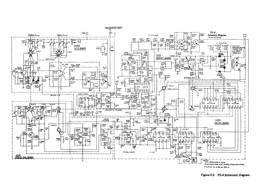
10 CHAPTER IV THEORY OF OPERATION 4-1. GENERAL. Refer to the block diagram in figure 4-1 for circuit operation VOLTAGE CONTROLLED OSCILLATOR (VCO). The VCO is a voltage controlled oscillator capable of operation over the frequency range of 10.5 to 41 MHz, and is used to provide the crystal oscillator signal required in the receiver/transmitter for proper operation D-BALANCE MIXER. A signal from the VCO is applied to the D-Balance Mixer, where it is mixed with the signal from the locked oscillator to produce an output in the frequency range of approximately 11 to 16 MHz LOCKED OSCILLATOR. The locked oscillator develops signals of 5, 10, 15, 20, and 25 MHz which are synchronized to a 5 MHz reference signal. The actual output of the locked oscillator is determined by the settings of the front panel switches. The output is zero for settings of O to 4.5 MHz, 5 MHz for settings of 5 to 9.5 MHz, etc. This output is mixed with the VCO to produce signals of 11 to 16 MHz which are fed to the bandpass filter BANDPASS FILTER. The bandpass filter following the D-Balance Mixer suppresses any higher order products from the mixer as well as the two inputs and their harmonics.
11
12 4-6. REFERENCE OSCILLATOR. The output of the bandpass filter is then mixed in the second mixer with the reference oscillator. The reference oscillator frequency determines the band edges of the injection output, that is, 16.1 as required in an R-4, vs for the SPR-4, vs as required by the 2-C (see paragraph 3-6). The resultant output from the second mixer is in the range of 1.5 to 6 MHz and is applied to the low pass filter to suppress any higher frequency outputs PHASE/FREQUENCY DETECTOR. The output of the low pass filter is applied to a programmable counter, which is programmed from the 1 MHz and 0.5 MHz controls, and divides the input by an appropriate number between 3 and 12 to produce an output near 0.5 MHz. The output is applied to the phase/frequency detector, where it is compared in phase and frequency with the resultant 0.5 MHz signal obtained by dividing the 5 MHz clock by 10. An error signal is developed in the phase/frequency detector which is applied to a voltage variable capacitor in the VCO, and forces the frequency to be such that the resultant input to the phase/frequency detector is the same frequency as that derived from the clock (500 khz) PROGRAMMABLE COUNTER. The programmable counter is controlled by the 1 MHz and 0.5 MHz controls, and covers a range count of 10, starting at 3, at dial setting 00.0, and progressing one count for an increase in the 0.5 position of a two count for each increase ín the 1 MHz control. The counter increases to 12 at the settíng of 4.5 and then starts over again at 5.0 and repeats every 5 MHz range of the FS SIGNALS PRESENT AT DIAL SETTING. The following is an example of actual signals present for the FS-4 set at a dial setting of 12.5 MHz: Dial setting = 12.5 MHz VCO Frequency = 23.6 Locked Oscillator = 10 MHz D-Bal. Mixer Output = = 13.6 Second Mixer Output = = 4 N = 8 N output = 4/8 = 0.5
13 CHAPTER V MAINTENANCE 5-1. ALIGNMENT. The FS-4 has been carefully aligned and tested at the factory for proper operation and should not be realigned unless required and then only by a knowledgeable and competent technician MHz CLOCK ALIGNMENT. Tune in and zero beat a signal from WWV using the internal crystal of the receiver. Without moving the frequency dial of the receiver, couple the receiver antenna to the FS-4 case or ground. Tune capacitor C303 for zero beat on the receiver. Refer to figures 5-1 and 5-2. NOTE A higher frequency of WWV signal provides greater accuracy, as the above process provides tuning of the 5 MHz clock by tuning in a harmonic REFERENCE OSCILLATOR ALIGNMENT. For a high degree of accuracy the reference oscillator should be tuned using a frequency counter connected to the injection output of the FS-4. Set the FS-4 dial to 00.0 and tune L406 for 11.1 MHz. NOTE If using a reference other than 9.6 MHz, tune the injection output frequency 1.5 MHz above the reference crystal frequency as specified in paragraph 3-6. This oscillator may be tuned for operation with very little frequency error merely by tuning for maximum RF voltage measured at test point A on bottom of parent board. NOTE It is not necessary to realign the oscillator when changing the crystal as specified in paragraph 3-6.
14
15 5-4. LOCKED OSCILLATOR ALIGNMENT. Tune the indicated coils for maximum RF output voltage measured at test point B (on bottom of parent board) when the FS-4 is tuned to the indicated dial setting: DIAL SETTING Mhz TUNE COIL 50 L L L L L VOLTAGE CONTROLLED OSCILLATOR ALIGNMENT. The VCO may be tuned using a frequency counter connected to the injection output of the FS-4. If the system is operational on most dial settings, the oscillator may be aligned by monitoring the control line voltage under locked conditions. FREQUENCY COUNTER METHOD. Disconnect the control line cable at the VCO board and apply a well filtered DC voltage of 1.5 V to the control line input of the VCO. (This may be obtained by using a potentiometer of at least 5 k Ohm connected across the 12 volt supply to ground.) Tune the oscillator for the indicated frequency when tuned to the specified setting: DIAL SETTING TUNE COIL FREQUENCY 00.0 L MHz 01.0 L MHz 03.0 L MHz 05.0 L MHz 07.0 L MHz 10.0 L MHz 20.0 L MHz
16 LOCKED LOOP METHOD. If the FS-4 is operational on most frequencies, the VCO may be tuned by monitoring the voltage at the control line under locked conditions. Do not disconnect the control line as in the method above. Connect a DC volt meter to the control line at the VCO board and tune the indicated coil for the specified control line voltage: DIAL SETTING TUNE COIL CONTROL LINE VOLTAGE 0,0 L V DC 1,0 L V DC 3,0 L V DC 5,0 L V DC 7,0 L V DC 10,0 L V DC 20,0 L V DC
17 NOTES
18 R-4C T-4XC TR-4C L-4B SPR-4 FS-4 MN-4 DRAKE AMATEUR PRODUCTS Receiver, covers the 160 meter through 10 meter amateur bands and up to fifteen additional 500 khz ranges. It has 8-pole crystal filter selectivity with passband tuning and transceives with the T-4XC with excellent sensitivity. Transmitter, covers the 160 through 10 meter amateur bands and most other frequencies between 1.5 and 30 MHz. It has 8-pole crystal filters for sideband selection. It may be used to transceive with the R-4C Transceiver, 300 Watt high frequency single-sideband unit covers the 80 meter through 10 meter amateur bands. Includes AM and CW modes, a linear, permeability-tuned VFO and two 8-pole crystal lattice filters. Linear Amplifier, built for continuous duty at full capacity Watts PEP on SSB Watts on AM, CW and RTTY. Covers the 80 meter through 10 meter bands. An all solid-state communications receiver which can be programmed with accessory crystals to cover 150 khz to 30 MHz. The SPR-4 receives AM, CW, SSB, (upper and lower) and may be powered from 120 VAC, 240 VAC, and 12 VDC. Frequency Synthesizer, built for use with R-4 series, SPR-4, 2-C receivers, and T-4X series transmitters. Antenna Matching Network, matches 50 Ohm transmitter output to coax antenna feedline with VSWR up to 5:1. An integrai Wattmeter reads forward power in Watts and VSWR directly. 200 Watts continuous duty output. MN-2000 Antenna Matching Network. Same as MN-4 except: 1000 Watts continuous duty output (2000 Watts PEP) and 3 antenna connectors switch-selectable from front panel. W-4 Wattmeter, reads forward and reflected power directly in Watts (VSWR from nomograph). Range: 200 and 2000 Watts full scale, 1.8 to 54 MHz. W V-4 TR-33C Wattmeter, reads forward and reflected power directly in Watts (VSWR from nomograph). Range: 100 and 1000 Watts full scale, 20 to 200 MHz. Transceiver, 2 meter VHF-FM, portable. Twelve channels, self-contained batteries and attached microphone. R CS-4 Remote Coax Switch, provides remote selection of up to five antennas, using only one main feedline. Allows grounding of unused antennas. Motor driven switches controlled from station located console. SSR-1 General Coverage Receiver, MHz continuous. All solid state. For information on any of our products, please feel free to write our Sales Department, 540 Richard Street, Miamisburg, Ohio or call direct,
19
20
Distribution Amplifiers 1
 Distribution Amplifiers 1-30dB PUT 49-750 MHz 43 db GA POWER DOUBLED P/N: 1002705 REVERSE GA M MAX DESCRIPTION The R.L. DRAKE models DA8642, DA8632,, and DA7533, are broadband distribution amplifiers designed
AMERITRON RCS-12 AUTOMATIC ANTENNA SWITCH
 AMERITRON RCS-12 AUTOMATIC ANTENNA SWITCH INSTRUCTION MANUAL PLEASE READ THIS MANUAL BEFORE OPERATING THIS EQUIPMENT! 116 Willow Road Starkville, MS 39759 USA 662-323-8211 Version 3B Printed in U.S.A.
WiMo Antennen und Elektronik GmbH Am Gäxwald 14, D Herxheim Tel. (07276) FAX 6978
 FAX 6978") 2m DISCOVERY LINEAR AMPLIFIER (GS 31) Operating Manual WiMo Antennen und Elektronik GmbH Am Gäxwald 14, D-76863 Herxheim Tel. (07276) 96680 FAX 6978 http://www.wimo.com e-mail: info@wimo.com INDEX 1. Specifications
2m DISCOVERY LINEAR AMPLIFIER (GS 31) Operating Manual WiMo Antennen und Elektronik GmbH Am Gäxwald 14, D-76863 Herxheim Tel. (07276) 96680 FAX 6978 http://www.wimo.com e-mail: info@wimo.com INDEX 1. Specifications
FR250 OPERATION MANUAL
 www.etoncorp.com FR250 OPERATION MANUAL SELF-POWERED RADIO AND FLASHLIGHT FR250 AM/FM Shortwave radio, flashlight, and cell phone charger TABLE OF CONTENTS DO YOU NEED HELP? We want you to thoroughly enjoy
CHALLENGER II HF LINEAR AMPLIFIER
 CHALLENGER II HF LINEAR AMPLIFIER (GS 35 Model) Operating Manual WiMo Antennen und Elektronik GmbH Am Gäxwald 14, D-76863 Herxheim Tel. (07276) 96680 FAX 6978 http://www.wimo.com e-mail: info@wimo.com
Instruction Manual. KP-1 Series 10M, 6M, 2M, 1-1/4M, 70 CM. IN-SHACK GaAsFET PRE-AMPLIFIER. MIRAGE KP-1 Pre-Amplifier
 Instruction Manual IN-SHACK GaAsFET PRE-AMPLIFIER KP-1 Series 10M, 6M, 2M, 1-1/4M, 70 CM Version A Copyright 1996, MIRAGE Communications Before operating this unit, please read these instructions completely.
Mini300PE OPERATION MANUAL AM/FM/SHORTWAVE RADIO
 www.etoncorp.com Mini300PE OPERATION MANUAL AM/FM/SHORTWAVE RADIO TABLE OF CONTENTS DO YOU NEED HELP? Here s how to contact us: From the United States: (800) 872-2228 From Canada: (800) 637-1648 From Everywhere
Mirage B-320-G FEATURES
 Mirage B-320-G The Mirage B-320-G is a VHF power amplifier designed for 2 meters covering 144-148 MHz. The Hi and Lo input selector switch makes this amp useable for both handheld and mobile transceivers.
MIRAGE BD-38-G DUAL BAND POWER AMPLIFIER
 MIRAGE BD-38-G DUAL BAND POWER AMPLIFIER MIRAGE BD-38-G Dual Band Amplifier INTRODUCTION: The Mirage BD-38-G is a 80/60 watt dual band power amplifier for use with today's dual band handie talkies operating
F R F R G
 w w w. e t o n c o r p. c o m F R 2 0 0 F R 2 0 0 G O P E R AT I O N M A N U A L A M / F M / S H O R T W A V E R A D I O TABLE OF CONTENTS DO YOU NEED HELP? Contact Us. Etón Corporation 1015 Corporation
JMAA-3600HR16-UL. Installation and Operation Instructions. Performance Series 360w RMS 4-Channel Amplifier Kit For Harley RoadGlide Ultra
 Performance Series 360w RMS 4-Channel Amplifier Kit For 2016-2018 Harley RoadGlide Ultra # JMAA-3600HR16-UL 2017 J&M Corporation. All rights reserved. 9/17 Installation and Operation Instructions Product
Performance Series 360w Amplifier Kit For Harley RoadGlide with Lower/Rear Speakers JMAA-3600HR15-RC
 Performance Series 360w Amplifier Kit For 2015-2018 Harley RoadGlide with Lower/Rear s # JMAA-3600HR15-RC 2017 J&M Corporation. All rights reserved. 9/17 Installation and Operation Instructions Product
INSTRUCTIONS FOR INSTALLATION AND OPERATION OF THE MEISSNER SIGNAL SHIFTER MODEL EX
 INSTRUCTIONS FOR INSTALLATION AND OPERATION OF THE MEISSNER SIGNAL SHIFTER MODEL EX I. INTRODUCTION A. The MEISSNER SIGNAL SHIFTER is a variable frequency exciter, with output over the entire ranges of
VC-300D VECTRONICS R. Digital Bar Graph Antenna Tuner. Owner's Manual. CAUTION: Read All Instructions Before Operating Equipment!
 VC-300D Digital Bar Graph Antenna Tuner CAUTION: Read All Instructions Before Operating Equipment! VECTRONICS R... the finest amateur radio products made 300 Industrial Park Road Starkville, MS 39759 (662)
GMINI 300PE AM/FM/Shortwave Radio OWNER S MANUAL
 GMINI 300PE AM/FM/Shortwave Radio OWNER S MANUAL Grundig Radio Line By www.etoncorp.com Grundig Radio Line By DO YOU NEED HELP? Contact Us Etón Corporation 1015 Corporation Way Palo Alto, CA 94303, USA.
JMAA-1800HR15. Installation and Operation Instructions. 180w Performance Series Amplifier Kit For Harley RoadGlide/ Ultra
 180w Performance Series Amplifier Kit For 2015-2018 Harley RoadGlide/ Ultra # JMAA-1800HR15 2017 J&M Corporation. All rights reserved. 9/17 Installation and Operation Instructions Product Description This
MFJ-203 Bandswitched Dip Meter
 MFJ-203 Bandswitched Dip Meter Thank you for purchasing the MFJ-203 Bandswitched Dip Meter. The MFJ-203 Bandswitched Dip Meter is a solid state bandswitched adaptation of the traditional grid dip meter.
HP 86290B RF PLUG-IN GHz HEWLETT PACKARD
 OPERATING AND SERVICE MANUAL. HP 86290B RF PLUG-IN 2.0-18.6 GHz HEWLETT PACKARD COPYRIGHT AND DISCLAIMER NOTICE Copyright - Agilent Technologies, Inc. Reproduced with the permission of Agilent Technologies
Introduction. Specifications. Features. Controls. Model 103
 Index Page # Model 103 2 Introduction 2 Specifications 2 Features 2 Controls 2 Hints and Tips 3 Input Sensitivity (typical) 3 RF Signal Strength Bargraph 3 Frequency Display Resolution 3 Model 104 4 Introduction
Model 1791 VHF Radio User's Manual
 Model 79 VHF Radio User's Manual ALL WEATHER INC 65 NATIONAL DRIVE SACRAMENTO, CA 95834 WWW.ALWEATHERINC.COM 79 VHF RADIO USER'S MANUAL CONTENTS INTRODUCTION... Description... Transmitter Module... Power
JAMP-700HR15-RCP. Installation and Operation Instructions. ROKKER XXRP 700w Amplifier Kit For Harley RoadGlide with Lower/Rear Speakers
 ROKKER XXRP 700w Amplifier Kit For 2015-2018 Harley RoadGlide with Lower/Rear s # JAMP-700HR15-RCP 2018 J&M Corporation. All rights reserved. 4/18 Installation and Operation Instructions Product Overview
2006 MFJ ENTERPRISES, INC.
 Model MFJ-207 INSTRUCTION MANUAL CAUTION: Read All Instructions Before Operating Equipment MFJ ENTERPRISES, INC. 300 Industrial Park Road Starkville, MS 39759 USA Tel: 662-323-5869 Fax: 662-323-6551 VERSION
INSTALLATION AND MAINTENANCE MANUAL FOR GROUND MONITOR GM-250 COPYRIGHT 1983 AMERICAN MINE RESEARCH, INC.
 INSTALLATION AND MAINTENANCE MANUAL FOR GROUND MONITOR GM-250 COPYRIGHT 1983 AMERICAN MINE RESEARCH, INC. MANUAL PART NUMBER 180-0036 ORIGINAL: 1-17-83 REVISION: B (8-26-86) NOT TO BE CHANGED WITHOUT MSHA
AIU-2 Installation Manual
 AIU-2 Installation Manual RESEARCH CONCEPTS INC. 9501 Dice Lane Lenexa, Kansas 66215 USA VOICE: (913) 422-0210 FAX: (913) 422-0211 www.researchconcepts.com support@researchconcepts.com Contents subject
XPR522 XPR540. XPR SERIES INSTALLATION / OWNER'S MANUAL Mobile Power Amplifiers
 XPR522 XPR540 XPR SERIES INSTALLATION / OWNER'S MANUAL Mobile Power Amplifiers Preparation Please read entire manual before installation. Due to the technical nature of amplifiers, it is highly recommended
HydroLynx Systems, Inc.
 Model 50386R-RP Receiver and Repeater Instruction Manual Document No: A102684 Document Revision Date: August, 2006 Receiving and Unpacking Carefully unpack all components and compare to the packing list.
DA6002D-DA10004D. INSTALLATION / OWNER'S MANUAL Mobile Power Amplifiers
 DA6002D-DA10004D INSTALLATION / OWNER'S MANUAL Mobile Power Amplifiers Preparation Please read entire manual before installation. Due to the technical nature of amplifiers, it is highly recommended that
Glass Electrode Meter
 Glass Electrode Meter INSTRUCTION MANUAL FOR Glass Electrode R/C Meter MODEL 2700 Serial # Date PO Box 850 Carlsborg, WA 98324 U.S.A. 360-683-8300 800-426-1306 FAX: 360-683-3525 http://www.a-msystems.com
Installation Instructions
 J&M STAGE-5 ROKKER XXR Custom 700w Amplifier Installation Kit for 2015-19 Harley Roadglide CVO Ultra # JAMP-700HR15-ULP-CVO 2019 J&M Corporation. All rights reserved. 4/19 Installation Instructions Product
Performance Series 360w 4-CH Amplifier Kit For Harley Street Glide with Lower/Rear Speakers JMAA-3600HC14-SG
 Performance Series 360w 4-CH Amplifier Kit For 2014-2018 Harley Street Glide with Lower/Rear s # JMAA-3600HC14-SG 2017 J&M Corporation. All rights reserved. 9/17 Installation and Operation Instructions
Yaesu FT-8800R Alignment
 DUAL BAND FM TRANSCEIVER Introduction and Precautions The FT-8800R has been carefully aligned at the factory for the specified performance across the 144 MHz and 430 MHz amateur bands. Realignment should
DA560D COMPACT SERIES. INSTALLATION / OWNER'S MANUAL Mobile Power Amplifiers
 DA560D COMPACT SERIES INSTALLATION / OWNER'S MANUAL Mobile Power Amplifiers Preparation Please read entire manual before installation. Due to the technical nature of amplifiers, it is highly recommended
OPERATION & SERVICE MANUAL FOR FC 110 AC POWER SOURCE
 OPERATION & SERVICE MANUAL FOR FC 100 SERIES AC POWER SOURCE FC 110 AC POWER SOURCE VERSION 1.3, April 2001. copyright reserved. DWG No. FC00001 TABLE OF CONTENTS CHAPTER 1 INTRODUCTION... 1 1.1 GENERAL...
RCI-6300F25/150. Owner's Manual. AM/FM Amateur Transceiver With Built-in Frequency Counter. Table of Contents. Downloaded from
 Table of Contents RCI-6300F25/150 AM/FM Amateur Transceiver With Built-in Frequency Counter PAGE Chapter 1 Specifications...... 2 Chapter 2 Installation...... 3 Installing the Radio... 3 Ignition Noise
Installation Instructions Hustler Collinear Two Meter Fixed Station Antenna Master Gainer Model G6-144B
 Installation Instructions Hustler Collinear Two Meter Fixed Station Antenna Master Gainer Model Warning INSTALLATION OF THIS PRODUCT NEAR POWER LINES IS DANGEROUS. FOR YOUR SAFETY, FOLLOW THE INSTALLATION
DL102 Counter Loop Amplifier
 DL102 Counter Loop Amplifier USER MANUAL MAN 234A Contents Overview...3 System Includes...3 Maintenance and Recycling Instructions...3 Safety Information...4 Quick Setup...5 Setup...6 Loop Amplifier...6
Frequency range: BAND RANGE MHz MHz
 INSTRUCTION SHEET NO. 20 POWER-MITE PM3 and PM3A DESCRIPTION The Power-Mite 3 and 3A are self-contained CW transceivers covering 40 and 20 meters. The receiver is compromised of a variable oscillator operating
1.0 General Description
 1.0 General Description Figure 1 Plug-N-Play Noise Blanker for the Collins KWM-2/2A The Collins Noise Blanker is designed to be a Plug-N-Play accessory for the Collins KWM-2/2A transceivers. It plugs directly
MFJ Enterprises, Inc. 300 Industrial Park Rd Starkville, MS USA
 MFJ Enterprises, Inc. 300 Industrial Park Rd Starkville, MS 39759 USA MFJ-870 SWR & Power Meter Instruction Manual This SWR & Power meter is a highly accurate RF meter for measuring Forward Power, Reflected
Warranty Terms & Conditions
 Warranty Terms & Conditions Is my guitar under warranty? How long, what specific parts? Ibanez Electric Guitars and Basses Limited Warranty Ibanez Electric Guitars and Basses sold in the United States
AMP-13 OPERATOR S MANUAL
 AMP-13 OPERATOR S MANUAL Version 2.0 Copyright 2008 by Vatell Corporation Vatell Corporation P.O. Box 66 Christiansburg, VA 24068 Phone: (540) 961-3576 Fax: (540) 953-3010 WARNING: Read instructions carefully
DA604D DA954D DA501D DA801D COMPACT SERIES. INSTALLATION / OWNER'S MANUAL Mobile Power Amplifiers
 DA604D DA954D DA501D DA801D COMPACT SERIES INSTALLATION / OWNER'S MANUAL Mobile Power Amplifiers Preparation Please read entire manual before installation. Due to the technical nature of amplifiers, it
JAMP-630HC14-ULP. Installation and Operation Instructions. ROKKER XXRP 630w Amplifier Kit For Harley Ultra/Ultra Ltd.
 ROKKER XXRP 630w Amplifier Kit For 2014-2018 Harley Ultra/Ultra Ltd. Fairing # JAMP-630HC14-ULP 2017 J&M Corporation. All rights reserved. 9/17 Installation and Operation Instructions Product Description
KWM-2/2A Transceiver THE COLLINS KWM-2/2A TRANSCEIVER
 KWM-2/2A Transceiver Click the photo to see a larger photo Click "Back" button on browser to return Courtesy of Norm - WA3KEY THE COLLINS KWM-2/2A TRANSCEIVER Unmatched for versatility, dependability and
RITEK RIT for Collins KWM-2/2A 10/01/2002
 RITEK RIT for Collins KWM-2/2A 10/01/2002 The RITEK RIT (receiver incremental tuning) control was developed for KWM-2/2A in 1992 to "clarify" received signals differing from the transmit frequency indicated
INSTRUCTION MANUAL. Specifications Electrical. Front-To-Back Ratio VSWR at Resonance Less than 1.5:1 Nominal Impedance. Mechanical
 300 Industrial Park Road, Starkville, MS 39759 Ph: (662) 323-8538 FAX: (662) 323-6551 TH-3JRS Tri-band HF 3 Elements Beam Covers 10, 15 and 20 Meters INSTRUCTION MANUAL WARNING Installation of this product
Installation & Operation Manual SAGA1-K Series Industrial Radio Remote Control
 Installation & Operation Manual SAGA1-K Series Industrial Radio Remote Control Gain Electronic Co. Ltd. Table Of Contents Safety Considerations ------------------------------------------------------------2
Synthesized Base Station Transmitter
 BST-25 OPERATOR S MANUAL (216 MHz) Synthesized Base Station Transmitter 357 West 2700 South Salt Lake City, Utah 84115 Phone: (800) 496-3463 Fax: (801) 484-6906 http://www.comtek.com INTRODUCTION BST-25
MFJ SIGNAL ENHANCER II
 MFJ SIGNAL ENHANCER II Model MFJ-752D INSTRUCTION MANUAL CAUTION: Read All Instruction Before Operating Equipment MFJ ENTERPRISES, INC. P.O. BOX 494, MISSISSIPPI STATE, MS 39762, USA 925-0037D-752D-REV
INTRODUCTION The B-24-G is a VHF band high power linear amplifier designed for the 144 MHz band. It has a maximum output power of 50W.
 CONTENTS INTRODUCTION...1 FEATURES... 1 SPECIFICATIONS...2 EXPLANATION OF FEATURES...3-5 INSTALLATION... 6 DIAGRAM OF RX GAIN... 7 B-24-G OPTIONAL ADAPTORS... 8-9 PRECAUTIONS... 10-11 CONNECTION DIAGRAM...12
2013 MFJ ENTERPRISES, INC.
 Model MFJ-868B MFJ Giant True Peak-Reading SWR/Wattmeter 1.8-60MHz MODEL MFJ-868B INSTRUCTION MANUAL CAUTION: Read All Instructions Before Operating Equipment MFJ ENTERPRISES, INC. 300 Industrial Park
XPA2100 XPA4100 XPA6100. XPA SERIES INSTALLATION/OWNER S MANUAL Mobile Power Amplifiers
 XPA2100 XPA4100 XPA6100 XPA SERIES INSTALLATION/OWNER S MANUAL Mobile Power Amplifiers XPA SERIES INSTALLATION Preparation Please read entire manual before installation. Due to the technical nature of
COMMANDER HF-2500 COMMANDER HF-2500 MAGNUM. Owner s Manual. PALSTAR, INC. Command Technologies Division 9676 N. Looney Road Piqua, Ohio U.S.A.
 COMMANDER HF-2500 COMMANDER HF-2500 MAGNUM Owner s Manual PALSTAR, INC. Command Technologies Division 9676 N. Looney Road Piqua, Ohio 45356 U.S.A. Customer Service and Sales Telephone: 800-773-7931 International:
MFJ-834 RF Ammeter. Introduction. Uses
 MFJ-834 RF Ammeter Introduction Congratulations on purchasing the MFJ-834 RF Ammeter. The MFJ-834 is designed for measuring in-line RF feedline current on 1.8-30 MHz while having low interaction on the
Advanced Test Equipment Rentals ATEC (2832)
") Established 1981 Advanced Test Equipment Rentals www.atecorp.com 800-404-ATEC (2832) A.H. Systems Model Active Monopole Antennas Active Monopole Antenna Series Operation Manual 1 TABLE OF CONTENTS INTRODUCTION
Established 1981 Advanced Test Equipment Rentals www.atecorp.com 800-404-ATEC (2832) A.H. Systems Model Active Monopole Antennas Active Monopole Antenna Series Operation Manual 1 TABLE OF CONTENTS INTRODUCTION
Model 7000 Low Noise Differential Preamplifier
 Model 7000 Low Noise Differential Preamplifier Operating Manual Service and Warranty Krohn-Hite Instruments are designed and manufactured in accordance with sound engineering practices and should give
Lesson 9: Base Stations
 Lesson 9: Base Stations Preparation for Amateur Radio Technician Class Exam Topics Home Stations Basic Station Layout RTTY and Data Communications Station Accessories Wavelengths Feed Lines Impedance-matching
MFJ-219/219N 440 MHz UHF SWR Analyzer TABLE OF CONTENTS
 MFJ-219/219N 440 MHz UHF SWR Analyzer TABLE OF CONTENTS Introduction...2 Powering The MFJ-219/219N...3 Battery Installation...3 Operation Of The MFJ-219/219N...4 SWR and the MFJ-219/219N...4 Measuring
LINCO MEASUREMENT MODEL CP-2B MASTER METER PROVER COUNTER INSTRUCTION MANUAL
 LINCO MEASUREMENT MODEL CP-2B MASTER METER PROVER COUNTER INSTRUCTION MANUAL ENGINEERED AUTOMATED SYSTEMS DESIGNERS ENGINEERS MANUFACTURERS SALES REPRESENTATIVES 4580 W. HWY 80 P.O. BOX 4096 MIDLAND, TEXAS
Broadband Step-Up Transformer. User Manual
 Broadband Step-Up Transformer User Manual 990-1930 09/2004 Introduction Introduction About this unit The APC Step-Up Transformer provides 220 V power from 60 VAC Broadband cable systems. Safety Electrical
Technician Licensing Class. Lesson 4. presented by the Arlington Radio Public Service Club Arlington County, Virginia
 Technician Licensing Class Lesson 4 presented by the Arlington Radio Public Service Club Arlington County, Virginia 1 Quiz Sub elements T6 & T7 2 Good Engineering Practice Sub element T8 3 A Basic Station
SDI SPECTRADYNAMICS, INC. LOW NOISE FREQUENCY REFERENCE OPERATING MANUAL
 SPECTRADYNAMICS, INC. LOW NOISE FREQUENCY REFERENCE LNFR-100E OPERATING MANUAL SPECTRADYNAMICS, INC 1849 Cherry St. Unit 2. Louisville, CO 80027 Phone: (303) 665-1852 Fax: (303) 604-6088 www.spectradynamics.com
INSTRUCTION MANUAL MODEL 2779 SUBCARRIER MODULATOR
 INSTRUCTION MANUAL MODEL 2779 SUBCARRIER MODULATOR Data, drawings, and other material contained herein are proprietary to Cross Technologies, Inc., and may not be reproduced or duplicated in any form without
WARNING: DO NOT PROCEED WITHOUT READING THIS PAGE.
 WARNING: DO NOT PROCEED WITHOUT READING THIS PAGE. The B-1030-G produces at least 300 watts of VHF R.F. power and is not to be taken lightly. Severe R.W. burns can be sustained at this power level! Power
AMP-12 OPERATOR S MANUAL
 AMP-12 OPERATOR S MANUAL Version 1.0 Copyright 2002 by Vatell Corporation Vatell Corporation P.O. Box 66 Christiansburg, VA 24068 Phone: (540) 961-3576 Fax: (540) 953-3010 WARNING: Read instructions carefully
HTA125A/250A. Power Amplifiers. Installation & Use Manual
 HTA125A/250A Power Amplifiers Installation & Use Manual Specifications subject to change without notice. 2010 Bogen Communications, Inc. All rights reserved. 54-5832-04B 1011 NOTICE: Every effort was made
LBI-4938C. Mobile Communications MASTR II POWER AMPLIFIER MODELS 4EF4A1,2,3. Printed in U.S.A. Maintenance Manual
 C Mobile Communications MASTR II POWER AMPLIFIER MODELS 4EF4A1,2,3 Printed in U.S.A. Maintenance Manual TABLE OF CONTENTS DESCRIPTION.................................................... 1 CIRCUIT ANALYSIS.................................................
TRANSDUCER IN-LINE AMPLIFIER
 TRANSDUCER IN-LINE Bi-Polar Model AMPLIFIER 2080 Arlingate Lane, Columbus, Ohio 43228 (614) 850-5000 Sensotec, Inc. 2080 Arlingate Lane Columbus, Ohio 43228 Copyright 1995 by Sensotec, Inc. all rights
Owner's Manual AM/FM STEREO RADIO WITH AUTO STOP CASSETTE PLAYER. Designed Specifically for the Marine and RV Environment
 Owner's Manual AM/FM STEREO RADIO WITH AUTO STOP CASSETTE PLAYER Designed Specifically for the Marine and RV Environment FACEPLATE CONTROLS DIAGRAM (Figure 1) 1 2 3 4 10 9 8 1 POWER BUTTON Press it to
JAMP-700HC06-SGP. Installation and Operation Instructions. ROKKER XXRP 700w Amplifier Kit For Harley Street Glide with Lower/Rear Speakers
 ROKKER XXRP 700w Amplifier Kit For 2006-2013 Harley Street Glide with Lower/Rear Speakers # JAMP-700HC06-SGP 2018 J&M Corporation. All rights reserved. 4/18 Installation and Operation Instructions Product
WARNING: DO NOT PROCEED WITHOUT READING THIS PAGE.
 WARNING: DO NOT PROCEED WITHOUT READING THIS PAGE. The B-2530-G produces at least 300 watts of VHF R.F. power and is not to be taken lightly. Severe R.W. burns can be sustained at this power level! Power
XIA3145 INSTALLATION/OWNER S MANUAL 2/1-Channel Mobile Power Amplifier
 XIA3145 INSTALLATION/OWNER S MANUAL 2/1-Channel Mobile Power Amplifier XIA3145 INSTALLATION Preparation Please read entire manual before installation. Due to the technical nature of amplifiers, it is highly
Radio Systems CP-15 Coupler Manual
 Radio Systems Manual Page 1 Contents Introduction... 2 Installation and Operating Instructions... 2 Carrier Current Broadcasting... 3 Free-Radiate Broadcasting... 3 Specifications... 5 Warranty... 5 Repair
Model 935A Current Source Operation Manual
 Model 935A Current Source Operation Manual Arbiter Systems, Inc. Paso Robles, CA 93446 U.S.A. ii Description This manual is issued for reference only, at the convenience of Arbiter Systems. Reasonable
Copyright 2012, R. Eckweiler & OCARC, Inc. Page 1 of 8
 HOM rev. new Heathkit of the Month #36: by Bob Eckweiler, AF6C Heathkit of the Month #36 - SB-301 HF Ham Band Receiver Heathkit SB-301 HF Ham Band Receiver Introduction: Shortly after graduating from college
hallicrafters PERFORMANCE SPECIFICATIONS MODEL: SR-2000 LATEST REVISION: 18 JAN 66 Code ident # Specification #
 hallicrafters PERFORMANCE SPECIFICATIONS MODEL: SR-2000 LATEST REVISION: 18 JAN 66 Code ident # 26916 Specification # 093-002154 I. GENERAL A. Power input 117V 50-60 cycles from a source capable of delivering
PARALLEL MULTI-AMP KIT for 7200 Series AMPLIFIERS INSTRUCTION SHEET
 2 5 0 7 W a r r e n S t r e e t, E l k h a r t, I N 4 6 5 1 6 U S A 5 7 4. 2 9 5. 9 4 9 5 w w w. A E T e c h r o n. c o m PARALLEL MULTI-AMP KIT for 7200 Series AMPLIFIERS INSTRUCTION SHEET Kit Contents:
HQ-31 HQ-15 USER S GUIDE SINGLE CHANNEL 31 BAND 1/3 OCTAVE GRAPHIC EQUALIZER DUAL CHANNEL 15 BAND 2/3 OCTAVE GRAPHIC EQUALIZER
 HQ-31 SINGLE CHANNEL 31 BAND 1/3 OCTAVE GRAPHIC EQUALIZER HQ-15 DUAL CHANNEL 15 BAND 2/3 OCTAVE GRAPHIC EQUALIZER USER S GUIDE GENERAL INFORMATION SINGLE CHANNEL 31 BAND 1/3 OCTAVE GRAPHIC EQUALIZER WITH
TABLE OF CONTENTS. 1) Introduction 2. 2) Unpacking your preamplifier 2. 3) Installing the preamp into your system 3
 Introduction 2. 2) Unpacking your preamplifier 2. 3) Installing the preamp into your system 3") TABLE OF CONTENTS 1) Introduction 2 2) Unpacking your preamplifier 2 3) Installing the preamp into your system 3 4) Operation of your preamplifier 6 5) Troubleshooting 8 6) Registration of your preamplifier
TABLE OF CONTENTS 1) Introduction 2 2) Unpacking your preamplifier 2 3) Installing the preamp into your system 3 4) Operation of your preamplifier 6 5) Troubleshooting 8 6) Registration of your preamplifier
KRAMER ELECTRONICS LTD. USER MANUAL MODEL: 912 Power Amplifier. P/N: Rev 2
 KRAMER ELECTRONICS LTD. USER MANUAL MODEL: 912 Power Amplifier P/N: 2900-000684 Rev 2 Contents 1 Introduction 1 2 Getting Started 2 2.1 Achieving the Best Performance 2 3 Overview 3 3.1 Defining the 912
MODERN AM BROADCAST STATIONS AM STEREO CQUAM WITH DDS
 MODERN AM BROADCAST STATIONS AM STEREO CQUAM WITH DDS DDS EXCITER OPERATING MANUAL 20W CARRIER - 80W PEP WHAT IS DDS? IT IS THE INITIALS OF THE WORDS DIRECT DIGITAL SYNTHESIZER. THAT MEANS: DIRECT DIGITAL
Vectronics VC-300D DIGITAL BARGRAPH ANTENNA TUNER
 Vectronics VC-300D DIGITAL BARGRAPH ANTENNA TUNER FEATURES The Vectronics VC-300D Antenna Tuner optimizes the performance of your antenna and transmitter, receiver, or transceiver by providing adjustable
MFJ ENTERPRISES, INC.
 Model MFJ-2013 INSTRUCTION MANUAL CAUTION: Read All Instructions Before Operating Equipment MFJ ENTERPRISES, INC. 300 Industrial Park Road Starkville, MS 39759 USA Tel: 662-323-5869 Fax: 662-323-6551 VERSION
COUPLING DECOUPLING NETWORK MODEL CDN-AF4
 COUPLING DECOUPLING NETWORK MODEL CDN-AF4 II Warranty Com-Power warrants to its Customers that the products it manufactures will be free from defects in materials and workmanship for a period of 2 years.
Model 4007DDS. 7 MHz Sweep Function Generator
 Model 4007DDS 7 MHz Sweep Function Generator 1 Model 4007DDS - Instruction Manual Limited Two-Year Warranty B&K Precision warrants to the original purchaser that its products and the component parts thereof,
411LA Broadband Power Amplifier
 411LA Broadband Power Amplifier HIGH RF VOLTAGES MAY BE PRESENT AT THE OUTPUT OF THIS UNIT. All operating personnel should use extreme caution in handling these voltages and be thoroughly familiar with
Table of Contents. Overview... 3
 User Guide Table of Contents Overview.................................................... 3 Powering A.C.E............................................... 4 Inputs & Outputs..............................................
TS-930: Installing the Inrad Roofing Filter Mod
 TS-930: Installing the Inrad Roofing Filter Mod The TS-930 roofing filter mod consists of a 6 pole, 4 to 5 khz wide filter followed by a high dynamic range, feedback amplifier. The amplifier provides enough
UNIVERSAL-DDS-VFO UDV ( 1 Hz to 10 MHz)
") UNIVERSAL-DDS-VFO UDV ( 1 Hz to 10 MHz) Connection and operating instructions 1. Introduction The UDV is the ideal device to adapt older, VFO-controlled transceivers to modern requirements regarding frequency
UNIVERSAL-DDS-VFO UDV ( 1 Hz to 10 MHz) Connection and operating instructions 1. Introduction The UDV is the ideal device to adapt older, VFO-controlled transceivers to modern requirements regarding frequency
SIR, RADAN and UtilityScan are registered trademarks of Geophysical Survey Systems, Inc..
 Copyright 2001-2017 Geophysical Survey Systems, Inc. All rights reserved including the right of reproduction in whole or in part in any form Published by Geophysical Survey Systems, Inc. 40 Simon Street
Model 5100F. Advanced Test Equipment Rentals ATEC (2832) OWNER S MANUAL RF POWER AMPLIFIER
 OWNER S MANUAL RF POWER AMPLIFIER") Established 1981 Advanced Test Equipment Rentals www.atecorp.com 800-404-ATEC (2832) OWNER S MANUAL Model 5100F RF POWER AMPLIFIER 0.8 2.5 GHz, 25 Watts Ophir RF 5300 Beethoven Street Los Angeles, CA 90066
Established 1981 Advanced Test Equipment Rentals www.atecorp.com 800-404-ATEC (2832) OWNER S MANUAL Model 5100F RF POWER AMPLIFIER 0.8 2.5 GHz, 25 Watts Ophir RF 5300 Beethoven Street Los Angeles, CA 90066
2001A. 200KHz Function Generator Instruction Manual. 99 Washington Street Melrose, MA Phone Toll Free
 2001A 200KHz Function Generator Instruction Manual 99 Washington Street Melrose, MA 02176 Phone 781-665-1400 Toll Free 1-800-517-8431 Visit us at www.testequipmentdepot.com WARRANTY Global Specialties
Model 3101, 3102 and 3103 Conical Log-Spiral Antennas
 Model 3101, 3102 and 3103 Conical Log-Spiral Antennas MANUAL EMC TEST SYSTEMS, L.P. SEPTEMBER 2002 EMC Test Systems, L.P. reserves the right to make changes to any products herein to improve functioning,
K1FO 12 ELEMENT 144/147 MHz YAGI
 K1FO 12 ELEMENT 144/147 MHz YAGI WARNING: INSTALLATION OF THIS PRODUCT NEAR POWER LINES IS DANGEROUS. FOR YOUR SAFETY FOLLOW THE INSTALLATION DIRECTIONS. Ariane Arrays, Inc. Copyright 2006 201 Hopedale
INSTRUCTION MANUAL MODEL 2455T SUBCARRIER MODULATOR
 INSTRUCTION MANUAL MODEL 2455T SUBCARRIER MODULATOR Data, drawings, and other material contained herein are proprietary to Cross Technologies, Inc., and may not be reproduced or duplicated in any form
DUAL LEVELAR. Two Channel Tube Compressor/Leveling Amplifier
 DUAL LEVELAR Two Channel Tube Compressor/Leveling Amplifier USER S GUIDE Introduction Thank you for purchasing the Dual Levelar and congratulations! You now own one of the most sophisticated pieces of
Classic Series Public Address Amplifiers C10 & C20 Models
 Classic Series Public Address Amplifiers C10 & C20 Models Installation and Use Manual 2009 Bogen Communications, Inc. All rights reserved. Specifications subject to change without notice. 54-5978-01B 0901
DANFYSIK A/S - DK-4040 JYLLINGE - DENMARK
 2 TABLE OF CONTENTS PAGE 1. INTRODUCTION AND SPECIFICATIONS. 1.1 Introduction... 4 1.1.1 Working principle....4 1.2 Warranty...5 2. RECEIVING AND UNPACKING. 2.1 Receiving the goods....6 2.2 Instructions
MFJ-969 Versa Tuner II Instruction Manual
 MFJ-969 Versa Tuner II Instruction Manual General Information The MFJ-969 is a 300 watt RF output power antenna tuner that will match any transmitter or transceiver to virtually any antenna. Peak or average
LDG TW-1 Talking Wattmeter
 LDG TW-1 Talking Wattmeter LDG Electronics 1445 Parran Road, PO Box 48 St. Leonard MD 20685-2903 USA Phone: 410-586-2177 Fax: 410-586-8475 ldg@ldgelectronics.com www.ldgelectronics.com 1 LDG TW-1 Talking