HP 86290B RF PLUG-IN GHz HEWLETT PACKARD
|
|
|
- Cuthbert Griffith
- 6 years ago
- Views:
Transcription
1 OPERATING AND SERVICE MANUAL. HP 86290B RF PLUG-IN GHz HEWLETT PACKARD
2 COPYRIGHT AND DISCLAIMER NOTICE Copyright - Agilent Technologies, Inc. Reproduced with the permission of Agilent Technologies Inc. Agilent Technologies, Inc. makes no warranty of any kind with regard to this material including, but not limited to, the implied warranties of merchantability and fitness for a particular purpose. Agilent Technologies, Inc. is not liable for errors contained herein or for incidental or consequential damages in connection with the furnishing, performance, or use of this material or data.
3 CERTIFICATION Hewlett-Packard Company certifies that this product met its published gt the time of shipment from the factory. Hewlett-Packard further certlpes that its calibration measurements are traceable to the United States National Bureau of Standards to the extent allowed by the Bureau s calibration facility* and to the calibration facilities of other International Standards Organization members. WARRANTY This Hewlett-Packard instrument product is warranted against defects in material and workmanship for a period of one year from date of shipment During the warranty period, Hewlett-Packard Company will. at its option, either repair or replace products which prove to be defective. For warranty service or repair, this product must be returned to a service facility designated by HP. Buyer shall prepay shipping charges to HP and HP shall pay shipping charges to return the product to Buyer. However. Buyer shall pay all shipping charges, duties, and taxes for products returned to HP from another country. HP warrants that its software and firmware designated by HP for use with an instrument will execute its programming instructions when properly installed on that instrument HP does not warrant that the operation of the instrument or software, or firmware will be uninterrupted or error free. LIMITATION OF WARRANTY The foregoing warranty shall not apply to defects resulting from improper or inadequate maintenance by Buyer, Buyer-supplied software or interfacing, unauthorized modification or misuse. operation outside of the environmental specifications for the product or improper site preparation or maintenance. NO OTHER WARRANTY IS EXPRESSED OR IMPLIED. HP SPECIFICALLY DISCLAIMS THE IMPLIED WARRANTIES OF MERCHANTABILITY AND FITNESS FOR A PARTICULAR PURPOSE. EXCLUSIVE REMEDIES THE REMEDIES PROVIDED HEREIN ARE BUYERS SOLE AND EXCLUSIVE REMEDIES. HP SHALL NOT BE LIABLE FOR ANY DIRECT, INDIRECT, SPECIAL, INCIDENTAL OR CONSEQUENTIAL DAMAGES. WHETHER BASED ON CONTRACT, TORT. OR ANY OTHER LEGAL THEORY. ASSISTANCE Product maintenance agreements and other customer assistance agreements are available for Hewlett- Packard products. For any assistance, contact your nearest Hewlett-Packard the back of this manual. Sales and Service OfJce. Addresses are provided at
4 HP 86290B RF PLUG-IN (Including Options 004 and 005) SERIAL NUMBERS This manual applies directly to HP Model 86290B RF Plug-In having serial number prelix 2227A. With changes described in Section VII, this manual also applies to instruments with serial numbers prefixed 1704A, 1727A, 1737A, 1742A, 1807A, 184OA, 1847A, 1852A, 1904A, 1908A, 1933A, 1952A, 2021A, 2034A, 2046A, 2109A, 2138A, and 2217A. For additional information about serial numbers, refer to INSTRUMENTS COVERED BY MANUAL in Section I. 0 Copyright HEWLE-IT-PACKARD COMPANY FOUNTAINGROVE PARKWAY, SANTA ROSA, CA U.S.A. MANUAL PART NUMBER: Microfiche Part Number: Printed: JULY 1984 c?!a HEWLETT PACKARD
5 Model 86290B Table of Contents CONTENTS Section Page I GENERAL INFORMATION l-l l-l. l l l-23. l-25. l-27. l-28. l-30. l-32. l-34. l-36. l-38. l-40. Introduction.... l-l Specifications... l-l Safety Considerations.... l-l Instruments Covered By Manual... l-l Description Option l-2 Option l-2 Accessories Supplied.... l-2 Equipment Required But Not Supplied... l-2 Equipment Available.... l-3 Service Accessories... l-3 Reversing Extender Board.... l-3 RF Section 36-Pin Extender Model 8755C Swept Amplitude Analyzer.... l-3 Power Meters and Crystal Detectors.... l-3 Model 8410B/841 IA Network Analyzer.... l-3 Recommended Test Equipment... l-3 II INSTALLATION l. Introduction l 2-3. Initial Inspection... 2-l 2-5. Preparation for Use Power Requirements l 2-8. Interconnections... 2-l Mating Connectors... 2-l Operating Environment Temperature l Humidity, Altitude... 2-l Frequency Scale Installation RF Plug-In Installation and Removal Installation Removal Storage and Shipment Environment Packaging Original Packaging Other Packaging III OPERATION l 3-l. Introduction l 3-3. Panel Features l 3-5. Operator s Checks l 3-7. Operating Instructions l 3-8. Internal Leveling l External Power Meter Leveling l Section Page External Crystal Detector Leveling Internal AM External AM External FM Frequency Response Phase-Lock Operation X-Y Recorder Operation X-Y Recorder Modilication Kit Operator s Maintenance IV PERFORMANCE TESTS... 4-l 4-l Test Record... 4-l 4-8. Frequency Range and Introduction Equipment Required l Accuracy Test... 4-l Frequency Stability Test Power Level and Variation Test Residual AM Test Spurious Signals Test Equivalent Source SWR Test External Frequency Modulation Test Amplitude Modulation Test V ADJUSTMENTS _ l. Introduction, Equipment Required Factory Selected Components l Safety Considerations Related Adjustments l Abbreviated RF Alignment Procedure Location of Test Points and Adjustment Frequency Modulation Balance Adjustments Sweep Control Adjustments Stop Sweep Adjustments YTO Frequency Range Adjustments YTM Slow Speed Tracking Adjustments YTM Slow Speed Tracking Adjustments (Alternate Procedure) YTM Bias Control Adjustment YTM and YTO Delay Compensation Adjustments ALC Adjustments Band Switch Overlap Adjustments i
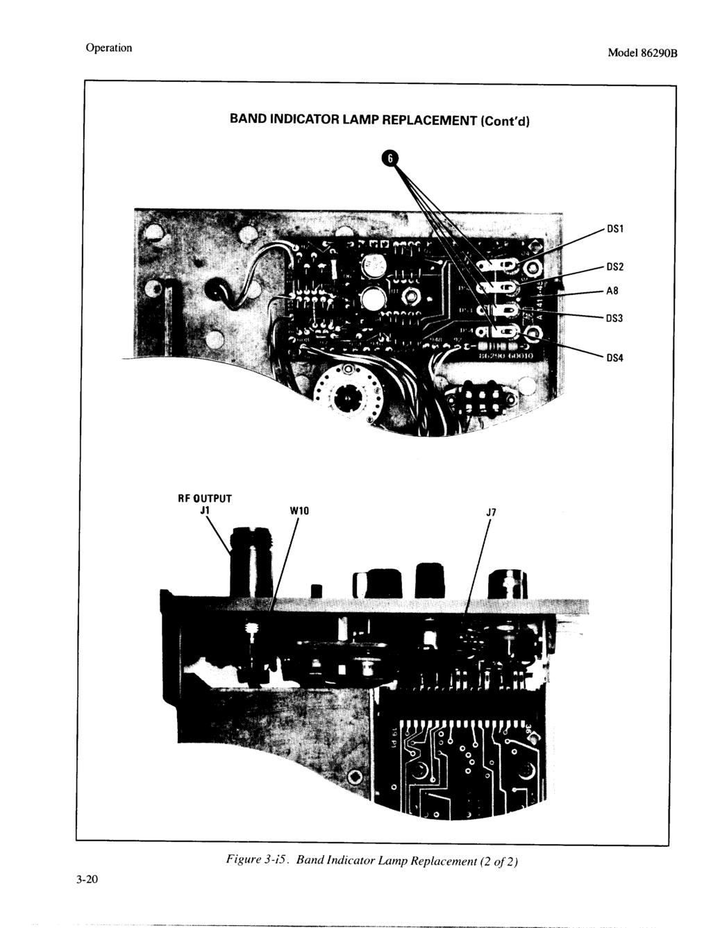
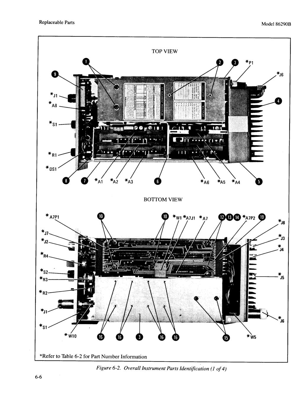
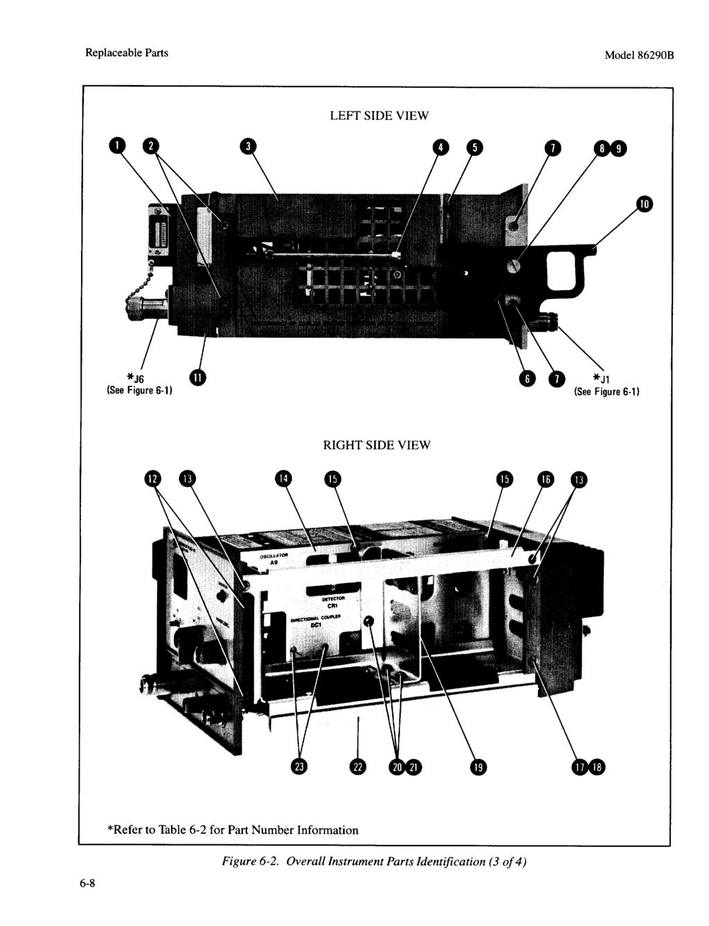
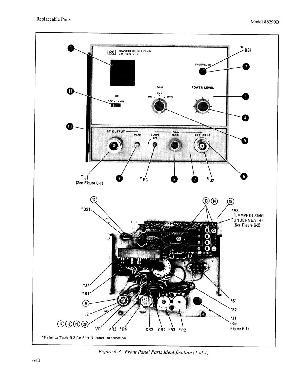
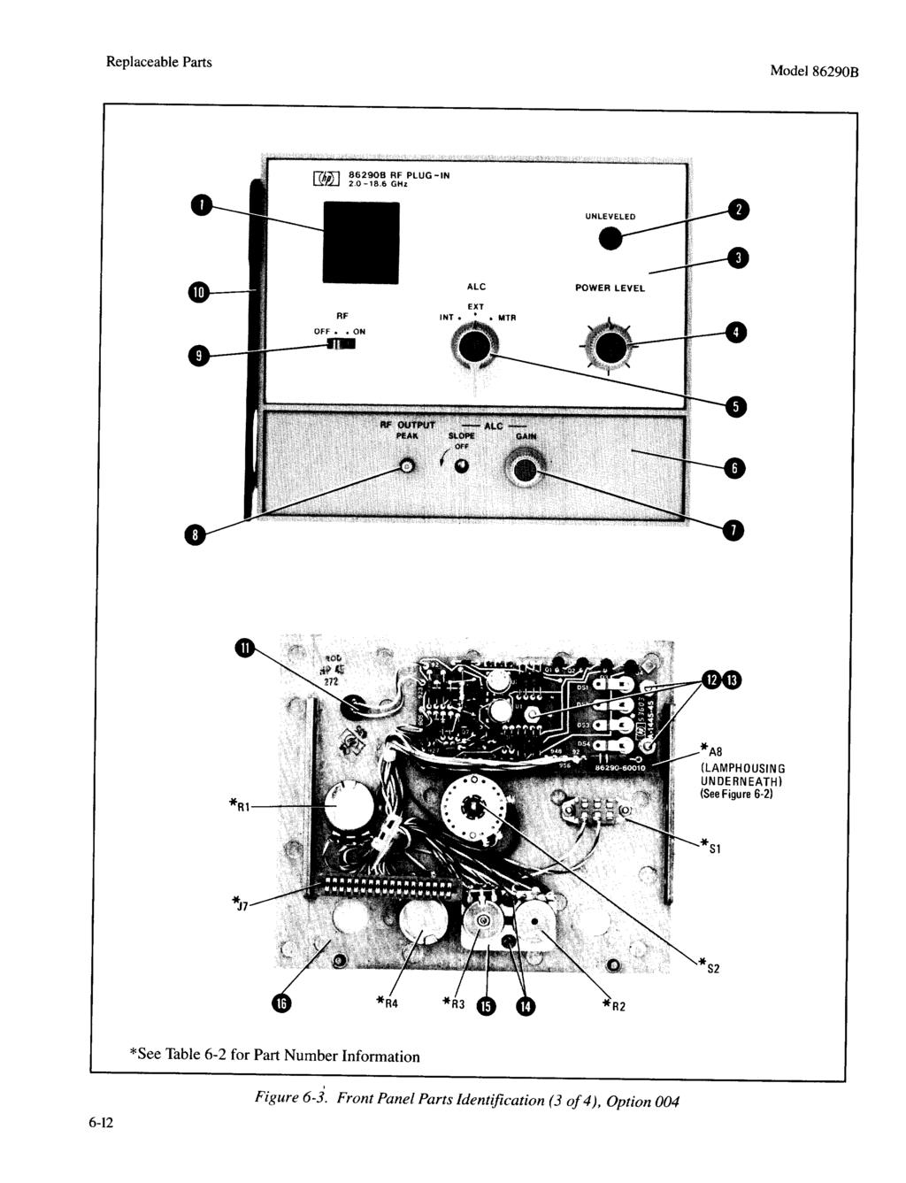
6 Table of Contents Model 86290B Section CONTENTS Page Frequency Reference Calibration Adjustment Frequency Modulation Sensitivity Adjustment VI REPLACEMENT PARTS Introduction Abbreviations l 6-5. Replaceable Parts List Parts Identification Ordering Instructions VII MANUAL BACKDATING CHANGES... 7-l 7-l. Introduction VIII SERVICE Introduction l... 8-l (Cont d) Section 8-3. Assembly Service Sheets...., Safety Troubleshooting _ Recommended Test Equipment Repair Band Indicator Lamp Replacement Cleaning Switches.....,.... ALC Switch Contact Detail _... Unleveled Lamp Removal and Replacement RF Section Removal and Installation Parts Locations, Test Points, and Adjustments Page... 8-l l ILLUSTRATIONS Figure Page l-l. Model 86290B RF Plug-In with Accessories Supplied _ O 1-2. Serial Number Plate ,.. _ l-l l-3. Service Accessories, HP Part Number l Reversing Extender Board, l-11 l-5. RF Section 36-Pin Extender, l Location of Mainframe Parts Pertinent to Frequency Scale and RF Plug-In Installation , Mainframe Front Panel in Open Position RF Plug-In Latch in Release Position l. Typical Recorder Plot of Device Under Test and Reference Plots Front Panel Controls, Connectors and Indicators Front Panel Controls, Connectors and Indicators, Option Rear Panel Connectors and Switch Rear Panel Connectors and Switch, Option Operator s Checks Unleveled RF Power Output for Sequential Sweep _. 3-l Leveled RF Power Output for Sequential Sweep Unleveled RF Power Output for Single Band (Band 1) _ 3-13 ii Figure Page Leveled RF Power Output for Single Band (Band 1) Oscillations Due to Excessive ALC Loop Gain External Power Meter Leveling External Crystal Detector Leveling Switch Positions and Functions for ALC Function Switch AlSl Band Indicator Lamp Replacement CW and Manual Sweep Accuracy Test Setup Swept Frequency Endpoint and Marker Accuracy Test Setup Frequency Stability Test Setup :l Load SWR Test Setup Residual FM Test Setup Residual FM Displayed on Spectrum Analyzer, Internal Leveling Test Setup Crystal Detector Leveling Test Setup Power Meter Leveling Test Setup Residual AM Test Setup Spurious Signals, Test Setup Equivalent Source Match SWR Test Setup Typical Pattern of a Swept SWR Measurement Graph for Converting Oscilloscope Trace to Source Match SWR External Frequency Modulation Test Setup
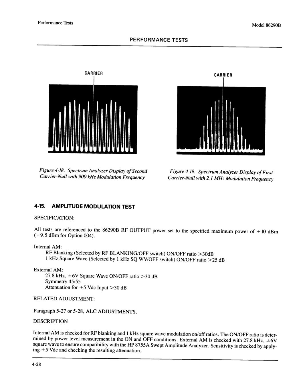
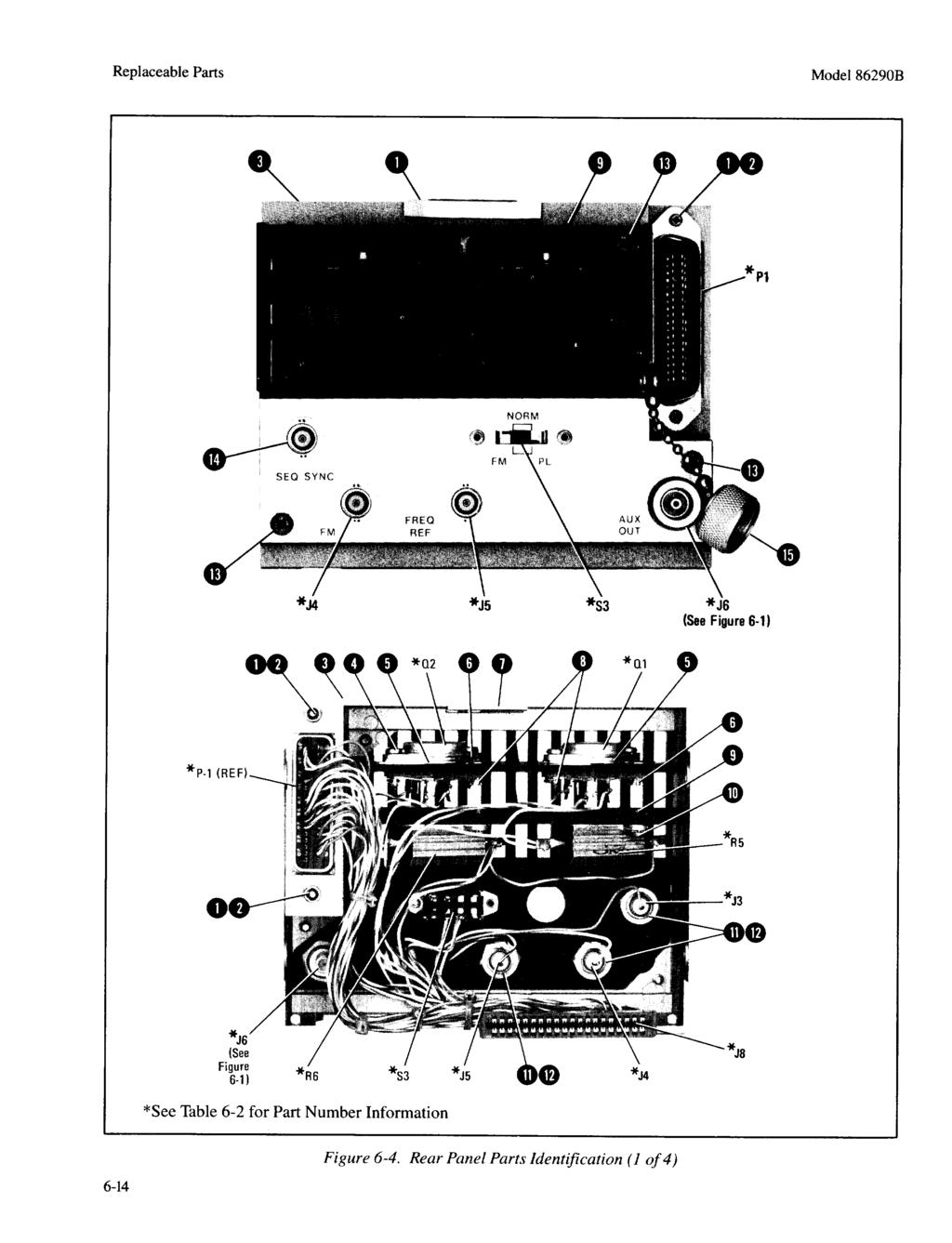
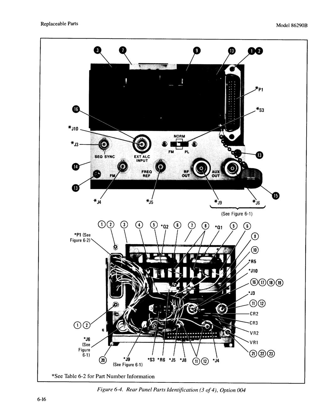
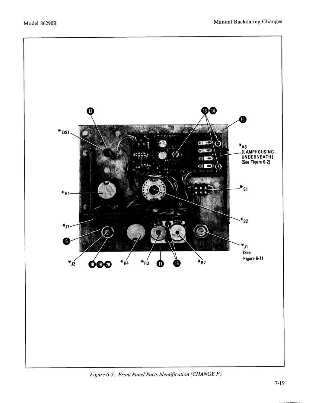
7 Model 86290B Table of Contents ILLUSTRATIONS (Cont d) Figur.e Page Spectrum Analyzer Display of Linear Frequency Modulation Spectrum Analyzer Display of Non-linear Frequency Modulation Spectrum Analyzer Display of Second Carrier-Null with 900 khz Modulation Frequency Spectrum Analyzer Display of First Carrier-Null with 2.1 MHz Modulation Frequency _ Amplitude Modulation Test Setup RF Section Labels for YTO and YTM Factory Selected Components and Abbreviated RF Alignment Procedure Modulation Balance Adjustments Setup Frequency Modulation Balance Adjustment Locations Sweep Control Adjustment Locations Stop Sweep Adjustment Locations Stop Sweep Timing Waveform l 1 YTO Frequency Range Adjustment Locations Function Generator Amplitude Adjustment Setup FM Amplifier Output YTM Frequency Tracking Adjustment Setup..... _ YTM Tracking Adjustment Locations Typical Output Waveform Displays YTM Bandpass Typical Output Waveform. Displays Drop-Out at Peak of YTM Bandpass When Squegging Occurs Typical Output Waveforms For an 86290B As Seen On a Spectrum Analyzer YTM Slow Speed Tracking Adjustments Setup YTM Slow Speed Tracking Adjustment Locations , 5-25 YTM Bias Control Adjustment Setup YTM Bias Control Adjustment Locations Pin Modulator Drive Voltage with Multiplier Bias Correctly Adjusted Delay Compensation Adjustments Setup Delay Compensation Adjustment Locations _ Fast Sweep Compensation Waveform Figure Page 8755C Calibration Setup ALC Adjustment Locations ALC Adjustment Setup Typical Detector Compensation Adjustment Waveforms PIN Upper Clamp Adjustment Setup GAIN PRESET Adjustment Setup Power Meter Leveling Setup Band Switch Overlap Adjustments Setup Band Switch Overlap Adjustment Locations Band Switch Overlap Adjustments Waveforms Typical Small Overlap Display Typical Large Overlap Display Frequency Reference Calibration Adjustment Locations Frequency Modulation Sensitivity Adjustment Locations RF Output Connector, Exploded View Overall Instrument Parts Identification Front Panel Parts Identification Rear Panel Parts Identification RF Section, Major Assembly and Component Locations RF Cable Assemblies Sweep Control Adjustments Location (CHANGE A) Band Sweep Overlap Adjustments Location (CHANGE A) A5 Sweep Control Assembly, Component Location (CHANGE A) RF Section, Major Assembly and Component Location (CHANGE B) Al ALC Assembly, Component Locations (CHANGE C) P/O Al ALC Assembly, Schematic (CHANGE C) Front Panel Parts Identification (CHANGE F) Rear Panel Parts Identification (CHANGE F) Front Panel Component Locations (CHANGE F) Lamp Driver Assembly and Front Panel Schematic (CHANGE F) Rear Panel Component Location Opt. 004 (CHANGE F)
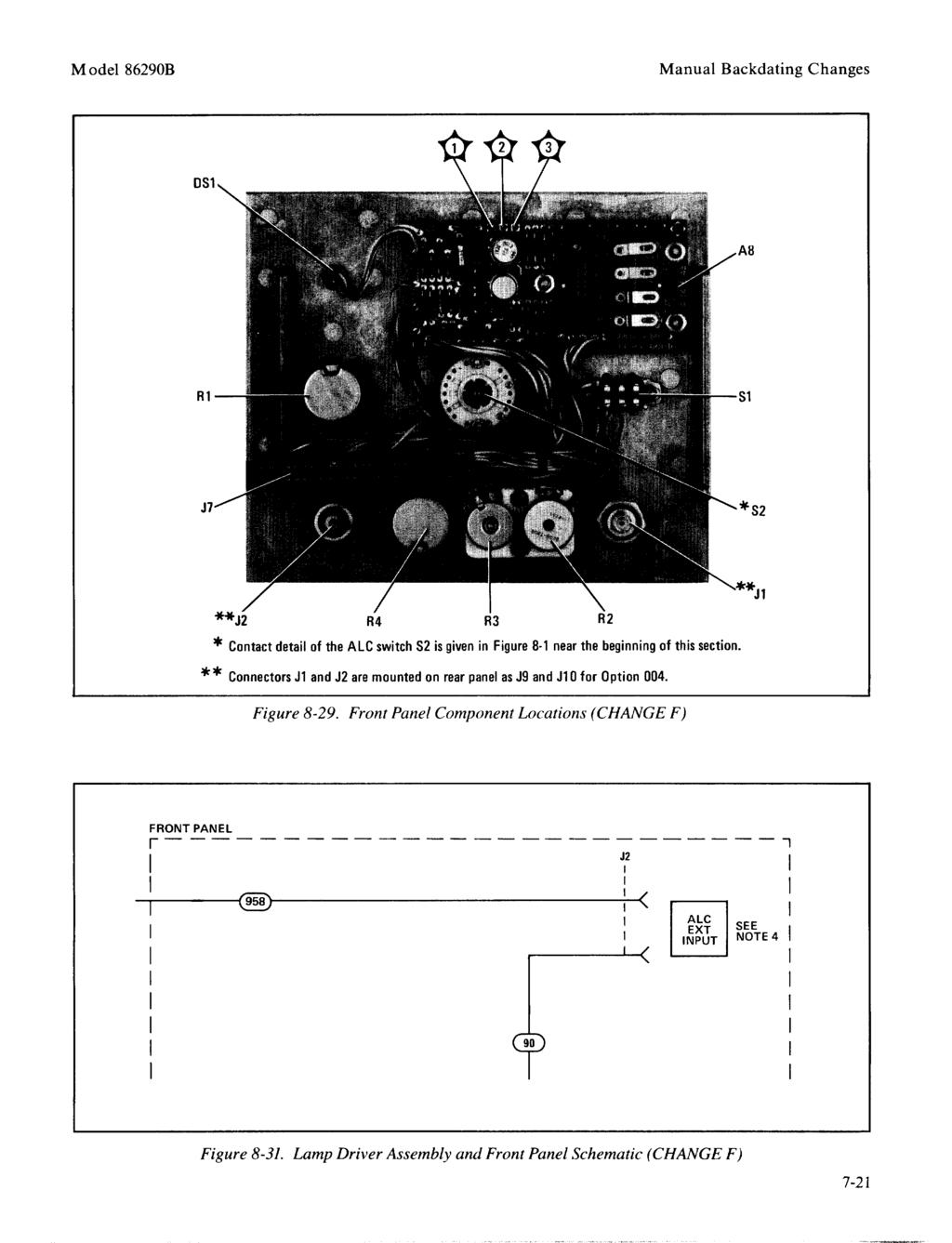
8 Table of Contents Model 86290B ILLUSTRATIONS Figur -e Page S l S l Rear Panel Wiring Diagram (CHANGE F) A6 Stop Sweep Assembly, Waveforms (CHANGE 1) A6 Stop Sweep Assembly Component Locations (CHANGE I) AlOAl YTM Bias Control Assembly, Component Locations (CHANGE K) AlOAl YTM Bias Control Assembly, Schematic (CHANGE K) ALC Switch S2 Contact Detail UNLEVELED Lamp Removal and Replacement Procedure General Information on Schematic Diagrams Schematic Diagram Notes Troubleshooting Block Diagram Troubleshooting Block Diagram... 8-l 1 Functional Block Diagram Al ALC Assembly, Waveforms Al ALC Assembly, Component Locations... S- 17 Al ALC Assembly, Schematic A2 YTM Driver Assembly, Component Locations A2 YTM Driver Assembly, Waveforms A2 YTM Driver Assembly, Test Points and Adjustment Locations A2 YTM Driver Assembly, Schematic A3 YTO Driver Assembly, Component Locations A3 YTO Driver Assembly, Waveforms A3 YTO Driver Assembly, Test Points and Adjustment Locations A3 YTO Driver Assembly, Schematic A4 FM Assembly, Component Locations A4 Assembly, Schematic A5 Sweep Control Assembly, Waveforms (Cont d) Figui ;e Page a A5 Sweep Control Assembly, Component Locations..... _ , Sweep Control Assembly, Schematic A6 Stop Sweep Assembly, Waveforms A6 Stop Sweep Assembly, Component Locations A6 Stop Sweep Assembly, Schematic A7 Motherboard, Component Locations A7 Motherboard, Interconnect Diagram Front Panel, Component Locations A8 Lamp Driver Assembly, Component Locations..... _ A8 Lamp Driver Assembly and Front Panel Schematic A9 YTO Component Locations Al 1Al Power Amplifier Board Assembly Component Locations AlOAl YTM Bias Control Assembly, Component Locations AlOAl YTM Bias Control Assembly, Schematic A12Al YTM Heater Control Assembly, Component Locations., AU41 YTM Heater Control Assembly, Schematic Rear Panel, Component Locations, Option Rear Panel, Component Locations Rear Panel Wiring Diagram WI Flexible Cable Assembly RF Section Removal and Installation Procedure RF Section, Major Assembly and Component Locations, Option RF Section, Major Assembly and Component Locations B Test Point Locations B Adjustment Locations B Major Assembly and Component Locations
9 Model 86290B Table of Contents TABLES Table Page Table Page l-l l-3. l-4. 2-l Specifications for 86290B Installed in 8620C Supplemental Characteristics for 86290B Installed in 8620C.... l-6 Parts Required for 86290B Options.... l-7 Recommended Test Equipment.... l-8 Model 86290B Mating Connectors Frequency Range and Accuracy Specifications l CW Model Accuracy at Low-Frequency Endpoints CW Mode Accuracy at Mid-Frequencies CW Mode Accuracy at High-Frequency Endpoints Manual Sweep Accuracy at Low-Frequency Endpoints Manual Sweep Accuracy at High-Frequency Endpoints Sweep Frequency Endpoint Accuracy Test Marker Accuracy Test Frequency Stability Specifications Frequency Change with Line Voltage Change Frequency Change with Power Level Change Frequency Change with 3:l Load SWR... 4-l 1 Residual FM Frequency Deviation Power Level and Power Variation Specifications l 3 Internal Leveling Power Level and Variation l l Low Frequency FM High Frequency FM Performance Test Record Controls Listed in Adjustment Sequence Factory Selected Components Adjustments By Assemblies Resistor A4R46* Selection Guide Reference Designations and Abbreviations Replaceable Parts Code List of Manufacturers Change Index Replaceable Parts (CHANGE A) Replaceable Parts (CHANGE 1) Voltages for A6 Stop Sweep Assembly (CHANGE I) Service Sheet Cross-Reference Voltages for Al ALC Assembly Voltages for A2 YTM Driver Assembly Voltages for A3 YTO Driver Assembly Voltages for A4 Frequency Modulation Voltages for A5 Sweep Control Assembly Voltages for A6 Stop Sweep Assembly Voltages for A8 Lamp Driver Assembly V
10 SAFETY CONSIDERATIONS GENERAL This product and related documentation must be reviewed for familiarization with safety markings and instructions before operation. This product has been designed and tested in accordance with international standards. SAFETY SYMBOLS n! f Instruction manual symbol: the product will be marked with this symbol when it is necessary for the user to refer to the instruction manual (refer to Table of Contents). Indicates hazardous voltages. Indicates earth (ground) terminal. The WARNING sign denotes a hazard. It calls attention to a procedure, practice, or the like, which, if not correctly performed could result in personal injury. Do not proceed beyond a WARNING sign until the indicated conditions are fully understood and met. The CAUTION sign denotes a hazard. It calls attention to an operating procedure, practice, or the like, which, if not correctly performed or adhered to, could result in damage to or destruction of part or all of the product. Do not proceed beyond a CAUTION sign until the indicated conditions are fully understood and met. SERVICING Any servicing, adjustment, maintenance, or repair of this product must bepe$ormed only by qual$ed personnel. Adjustments described in this manual may be per$ormed with power supplied to the product while protective covers are removed. Energy available at many points may, if contacted, result in personal injury. vi
11 General Information Model 86290B SCALES FOR 862OC RF TEST CABLE* EXTENDER BOARD* *NOTE: See paragraph 1-24 for part number information 1-o Figure I-I. Model 8629OB RF PI ug -I n with Accessories Supplied
12 Model 86290B General Information SECTION I GENERAL INFORMATION l-l. INTRODUCTION 1-2. This Operating and Service manual contains information required to install, operate, test, adjust, and service the Hewlett-Packard Model 86290B RF Plug- In. Figure I-l shows the instrument and accessories supplied. This section covers instrument identification, description, options, accessories, specifications, and other basic information. l-3. This manual is divided into eight sections which provide information as follows: with the instrument for use by the operator. Additional copies of the Operating Information Supplement can be ordered through your nearest Hewlett-Packard office. The part number is listed on the title page. l-5. Also listed on the title page of this manual is a Microfiche part number. This number can be used to order 4x6-inch microfilm transparencies of the manual. Each microfiche contains up to 60 photo-duplicates of the manual pages. The microfiche package also includes the latest Manual Changes supplement as well as all pertinent Service Notes. a. b. C. d. e. f. SECTION I, GENERAL INFORMATION, contains the instrument description and specifications as well as the accessory and recommended test equipment list. SECTION II, INSTALLATION, contains information relative to receiving inspection, preparation for use, mounting, packing, and shipping. SECTION III, OPERATION, contains operating instructions for the instrument. SECTION IV, PERFORMANCE TESTS, contains information required to verify that instrument performance is in accordance with published specifications. SECTION V, ADJUSTMENTS, contains information required to properly adjust and align the instrument after repair. SECTION VI, REPLACEABLE PARTS, contains information required to order all parts and assemblies. l-6. SPECIFICATIONS 1-7. Instrument specifications are listed in Table l-l. These specifications are the performance standards or limits against which the instrument is tested. Table l-2 lists supplemental characteristics. Supplemental characteristics are not specifications but are typical characteristics included as additional information for the user Safety Considerations l-9. This product has been manufactured and tested in accordance with international safety standards. Before operation, this product and related documentation must be reviewed for familiarization with safety markings and instructions. A complete listing of Safety Considerations precedes Section I of this manual. I-10. INSTRUMENTS COVERED BY MANUAL FACTORY INSTALLED OPTIONS I SERIAL NUMBER t \ PREFIX SUFFIX -- g. h. SECTION VII, MANUAL CHANGES, contains backdating information to make this manual compatible with earlier equipment configurations. SECTION VIII, SERVICE, contains descriptions of the circuits, schematic diagrams, parts location diagrams, and troubleshooting procedures to aid the user in maintaining the instrument. l-4. Supplied with this manual is an Operating Information Supplement. The Supplement is a copy of the first three sections of this manual, and should be kept Figure 1-2. Serial Number Plate l-11. Attached to the instrument is a serial number nlate (Figure l-2). The serial number is in two parts. The first four digits and letter are the serial number prefix; the last five digits are the suffix. The prefix is the same for all identical instruments; it changes only when a change is made to the instrument. The suffix, however, is assigned sequentially and is different for each instrument, The contents of this manual apply to instruments with the serial number prefix(es) listed under SERIAL NUMBERS on the title page. 1-l
13
14
15
16
17
18
19
20
21
22
23
24
25
26
27
28
29
30
31
32
33
34
35
36
37
38
39
40
41
42
43
44
45
46
47
48
49
50
51
52
53
54
55
56
57
58
59
60
61
62
63
64
65
66
67
68
69
70
71
72
73
74
75
76
77
78
79
80
81
82
83
84
85
86
87
88
89
90
91
92
93
94
95
96
97
98
99
100
101
102
103
104
105
106
107
108
109
110
111
112
113
114
115
116
117
118
119
120
121
122
123
124
125
126
127
128
129
130
131
132
133
134
135
136
137
138
139
140
141
142
143
144
145
146
147
148
149
150
151
152
153
154
155
156
157
158
159
160
161
162
163
164
165
166
167
168
169
170
171
172
173
174
175
176
177
178
179
180
181
182
183
184
185
186
187
188
189
190
191
192
193
194
195
196
197
198
199
200
201
202
203
204
205
206
207
208
209
210
211
212
213
214
215
216
217
218
34134A AC/DC DMM Current Probe. User s Guide. Publication number April 2009
 User s Guide Publication number 34134-90001 April 2009 For Safety information, Warranties, Regulatory information, and publishing information, see the pages at the back of this book. Copyright Agilent
VT1586A Rack Mount Terminal Panel Installation and User s Manual
 VT1586A Rack Mount Terminal Panel Installation and User s Manual Manual Part Number: 82-0095-000 Rev. June 16, 2003 Printed in U.S.A. Certification VXI Technology, Inc. certifies that this product met
8472B Crystal Detector. Operating and Service Manual
 8472B Crystal Detector Operating and Service Manual Part number: 08472-90022 Printed in USA Print Date: May 2001 Supersedes: April 1999 Notice The information contained in this document is subject to change
Signal Analysis Measurement Guide
 Signal Analysis Measurement Guide Agilent Technologies EMC Series Analyzers This guide documents firmware revision A.08.xx This manual provides documentation for the following instruments: E7401A (9 khz-
Model 5100F. Advanced Test Equipment Rentals ATEC (2832) OWNER S MANUAL RF POWER AMPLIFIER
 OWNER S MANUAL RF POWER AMPLIFIER") Established 1981 Advanced Test Equipment Rentals www.atecorp.com 800-404-ATEC (2832) OWNER S MANUAL Model 5100F RF POWER AMPLIFIER 0.8 2.5 GHz, 25 Watts Ophir RF 5300 Beethoven Street Los Angeles, CA 90066
Established 1981 Advanced Test Equipment Rentals www.atecorp.com 800-404-ATEC (2832) OWNER S MANUAL Model 5100F RF POWER AMPLIFIER 0.8 2.5 GHz, 25 Watts Ophir RF 5300 Beethoven Street Los Angeles, CA 90066
Agilent 8473B/C Crystal Detector. Operating and Service Manual
 Agilent 8473B/C Crystal Detector Operating and Service Manual Agilent Part Number: 08473-90003 Printed in USA Print Date: June 2001 Supersedes: May 1990 Notice The information contained in this document
Agilent Technologies 8494A/B, 8495A/B, and 8496A/B Attenuators. Operating and Service Manual
 Agilent Technologies 8494A/B, 8495A/B, and 8496A/B Attenuators Operating and Service Manual Agilent Part Number: 08494-90008 Printed in USA Print Date: April 2002 Supersedes: October 2000 Notice The information
Operating and Service Manual
 Operating and Service Manual Agilent 8490D/G, 8491A/B, 8493A/B/C Coaxial Fixed Attenuators Agilent 11581A, 11582A, 11583C Attenuator Sets Manufacturing Part Number: 08491-90077 Printed in Malaysia Print
Agilent Technologies 355C, D, E, F VHF Attenuators. Operating and Service Manual
 Agilent Technologies 355C, D, E, F VHF Attenuators Operating and Service Manual Agilent Part Number: 00355-90051 Printed in USA April 2002 Supersedes: November 2001 Notice The information contained in
GM8036 Laser Sweep Optical Spectrum Analyzer. Programming Guide
 GM8036 Laser Sweep Optical Spectrum Analyzer Programming Guide Notices This document contains UC INSTRUMENTS CORP. proprietary information that is protected by copyright. All rights are reserved. This
SERVICE MANUAL. GPIB DC Power Supplies Agilent Series 654xA, 655xA, 664xA, 665xA. For instruments with Serial Numbers:
 SERVICE MANUAL GPIB DC Power Supplies Agilent Series 654xA, 655xA, 664xA, 665xA For instruments with Serial Numbers: Agilent Model 6541A: US36360101 and above * Agilent Model 6542A: US36360101 and above
Keysight Series 654xA, 655xA, 664xA, 665xA GPIB DC Power Supplies
 Keysight Series 654xA, 655xA, 664xA, 665xA GPIB DC Power Supplies Service Manual CERTIFICATION Keysight Technologies certifies that this product met its published specifications at time of shipment from
AMP-13 OPERATOR S MANUAL
 AMP-13 OPERATOR S MANUAL Version 2.0 Copyright 2008 by Vatell Corporation Vatell Corporation P.O. Box 66 Christiansburg, VA 24068 Phone: (540) 961-3576 Fax: (540) 953-3010 WARNING: Read instructions carefully
MODEL 3810/2 Line Impedance Stabilization Network
 EMC TEST SYSTEMS FEBRUARY 1996 REV C PN 399197 MODEL 3810/2 Line Impedance Stabilization Network OPERATION MANUAL USA P.O. Box 80589 Austin, Texas 78708-0589 2205 Kramer Lane, Austin, Texas 78758-4047
Agilent X-Series Signal Analyzer This manual provides documentation for the following X-Series Analyzer: CXA Signal Analyzer N9000A
 Agilent X-Series Signal Analyzer This manual provides documentation for the following X-Series Analyzer: CXA Signal Analyzer N9000A N9000A CXA Functional Tests Notices Agilent Technologies, Inc. 2006-2008
TECHNICAL MANUAL OPERATOR'S, ORGANIZATIONAL, DIRECT SUPPORT, AND GENERAL SUPPORT MAINTENANCE MANUAL (INCLUDING REPAIR PARTS AND SPECIAL TOOLS LIST)
") TM 11-6625-2781-14&P-5 TECHNICAL MANUAL OPERATOR'S, ORGANIZATIONAL, DIRECT SUPPORT, AND GENERAL SUPPORT MAINTENANCE MANUAL (INCLUDING REPAIR PARTS AND SPECIAL TOOLS LIST) FOR PLUG-IN, LOW FREQUENCY (SPECTRUM
TM 11-6625-2781-14&P-5 TECHNICAL MANUAL OPERATOR'S, ORGANIZATIONAL, DIRECT SUPPORT, AND GENERAL SUPPORT MAINTENANCE MANUAL (INCLUDING REPAIR PARTS AND SPECIAL TOOLS LIST) FOR PLUG-IN, LOW FREQUENCY (SPECTRUM
SPM-50 RF Spectrum Power Meter PC Software User Manual
 SPM-50 RF Spectrum Power Meter PC Software User Manual Shineway Technologies, Inc. Notices Copyright 2014, ShinewayTech, All rights reserved. No part of this manual may be reproduced in any form or by
Calibration Guide. 8590L Spectrum Analyzer
 Calibration Guide 8590L Spectrum Analyzer Manufacturing Part Number: 08590-90315 Supersedes: 08590-90269 Printed in USA April 2001 Copyright 1994-1995, 2000-2001 Agilent Technologies, Inc. The information
PCO-7114 Laser Diode Driver Module Operation Manual
 PCO-7114 Laser Diode Driver Module Operation Manual Directed Energy, Inc. 1609 Oakridge Dr., Suite 100, Fort Collins, CO 80525, (970) 493-1901 sales@ixyscolorado.com www.ixyscolorado.com Manual Document
2001A. 200KHz Function Generator Instruction Manual. 99 Washington Street Melrose, MA Phone Toll Free
 2001A 200KHz Function Generator Instruction Manual 99 Washington Street Melrose, MA 02176 Phone 781-665-1400 Toll Free 1-800-517-8431 Visit us at www.testequipmentdepot.com WARRANTY Global Specialties
User s Guide. Agilent 16441A R-Box. Agilent Part No Printed in Japan January Edition 4
 User s Guide Agilent 16441A R-Box Agilent Part No. 16441-90000 Printed in Japan January 2000 Edition 4 Legal Notice The information contained in this document is subject to change without notice. Copyright
Operating and Service Guide
 Operating and Service Guide Agilent Technologies 11867A RFLimiter ---~~:{. Agilent Technologies. ~ :.. Manufacturing Part Number: 11867-95 Printed in USA June 1995 Copyright 1995-21 Agilent Technologies,
Directed Energy, Inc Oakridge Dr., Suite 100, Fort Collins, CO
 PCO-7121 Laser Diode Driver Module Operation Manual Directed Energy, Inc. 1609 Oakridge Dr., Suite 100, Fort Collins, CO 80525 sales@ixyscolorado.com www.ixyscolorado.com Contents Contents... 3 Safety...
INSTRUCTION MANUAL LKG 601 Electrical Safety Analyzer
 INSTRUCTION MANUAL LKG 601 Electrical Safety Analyzer 110 Toledo Street Farmingdale, NY 11735 USA http://www.netech.org 510-USER-Manual Rev3 10/29/2007 Dear User, We appreciate your purchase of the LKG
Signal Forge 1800M Frequency Expansion Module. 1.0 GHz to 1.8 GHz. User Manual
 TM TM Signal Forge 1800M Frequency Expansion Module 1.0 GHz to 1.8 GHz User Manual Technical Support Email: Support@signalforge.com Phone: 512.275.3733 x2 Contact Information Web: www.signalforge.com
Keysight 86205B RF Bridge
 Keysight 86205B RF Bridge Operating and Service Manual Notices Keysight Technologies 2011, 2014 No part of this manual may be reproduced in any form or by any means (including electronic storage and
HP Part No {90505
 User's Guide HP 8510 Pulsed-RF Network Analyzer ABCDE HP Part No. 08510{90505 Printed in USA March 1995 Notice The information contained in this document is subject to change without notice. Hewlett-Packard
Agilent 4396B Network/Spectrum/Impedance Analyzer PERFORMANCE TEST MANUAL SERIAL NUMBERS. This manual applies directly to instruments with serial
 Agilent 4396B Network/Spectrum/Impedance Analyzer PERFORMANCE TEST MANUAL SERIAL NUMBERS This manual applies directly to instruments with serial number prex JP1KE, or rmware revision 1.01 and below. For
CSM-S USER S MANUAL TRIGGER DISTRIBUTION MODULE Release April 7, VXI Technology, Inc.
 CSM-S-11056 TRIGGER DISTRIBUTION MODULE USER S MANUAL 82-0051-000 Release April 7, 2003 VXI Technology, Inc. 2031 Main Street Irvine, CA 92614-6509 (949) 955-1894 bus 2 VXI Technology, Inc. www.vxitech.com
Amplified Photodetectors
 Amplified Photodetectors User Guide (800)697-6782 sales@eotech.com www.eotech.com Page 1 of 6 EOT AMPLIFIED PHOTODETECTOR USER S GUIDE Thank you for purchasing your Amplified Photodetector from EOT. This
Model 9305 Fast Preamplifier Operating and Service Manual
 Model 9305 Fast Preamplifier Operating and Service Manual This manual applies to instruments marked Rev 03" on rear panel. Printed in U.S.A. ORTEC Part No.605540 1202 Manual Revision B Advanced Measurement
Agilent E5505A Phase Noise Measurement System
 Agilent E5505A Phase Noise Measurement System Notice: This document contains references to Agilent. Please note that Agilent s Test and Measurement business has become Keysight Technologies. For more information,
Signal Forge 2500M Frequency Expansion Module. 1.5 GHz to 2.6 GHz. User Manual
 TM TM Signal Forge 2500M Frequency Expansion Module 1.5 GHz to 2.6 GHz User Manual Technical Support Email: Support@signalforge.com Phone: 512.275.3733 x2 Contact Information Web: www.signalforge.com Sales
Introduction to New Features
 Introduction to New Features Agilent Technologies 8510C Network Analyzer Revision 7.XX (7.00 and Greater) Part Number 11575-90024 Printed in USA March 1995 Edition 1 Certification Hewlett-Packard Company
MODEL FS-4 INSTRUCTION MANUAL R.L. DRAKE COMPANY, MIAMISBURG, OHIO, U.S.A.
 MODEL FS-4 F R E Q U E N C Y S Y N T H E S I Z E R INSTRUCTION MANUAL R.L. DRAKE COMPANY, MIAMISBURG, OHIO, U.S.A. LIMITED WARRANTY R. L. DRAKE COMPANY warrants to the original purchaser that this product
Agilent N2902A 9000 Series Oscilloscope Rack Mount Kit
 Agilent N2902A 9000 Series Oscilloscope Rack Mount Kit Installation Guide Agilent Technologies Notices Agilent Technologies, Inc. 2009 No part of this manual may be reproduced in any form or by any means
1.5µm PbSe Power Detector
 1.5µm PbSe Power Detector User Guide (800)697-6782 sales@eotech.com www.eotech.com Page 1 of 7 EOT 1.5-5µm PbSe POWER DETECTOR USER S GUIDE Thank you for purchasing your 1.5-5µm PbSe Power Detector from
Non-amplified High Speed Photodetectors
 Non-amplified High Speed Photodetectors User Guide (800)697-6782 sales@eotech.com www.eotech.com Page 1 of 6 EOT NON-AMPLIFIED HIGH SPEED PHOTODETECTOR USER S GUIDE Thank you for purchasing your Non-amplified
E2621A and E2622A Probe Adapters for Infiniium Oscilloscopes. User s Guide. Publication number E September 2002
 User s Guide sa Publication number E2621-92003 September 2002 For Safety, Regulatory, and publishing information, see the pages at the back of this book. Copyright Agilent Technologies 1999-2002 All Rights
COMBILOG ANTENNA MODEL AC MHz. rev: 0202
 COMBILOG ANTENNA 30-2000 MHz MODEL AC-220 rev: 0202 WARRANTY All equipment manufactured by Com-Power Corporation is warranted against defects in material and workmanship for a period of two (2) years from
Operator s Manual. PP016 Passive Probe
 Operator s Manual PP016 Passive Probe 2017 Teledyne LeCroy, Inc. All rights reserved. Unauthorized duplication of Teledyne LeCroy documentation materials is strictly prohibited. Customers are permitted
Amplified High Speed Photodetectors
 Amplified High Speed Photodetectors User Guide 3340 Parkland Ct. Traverse City, MI 49686 USA Page 1 of 6 Thank you for purchasing your Amplified High Speed Photodetector from EOT. This user guide will
 HP 8901A Modulation Analyzer 150 khz to 1300 MHz Product Overview Measurements* Frequency Range: 150 khz to 1300 MHz Resolution: 10 Hz below 1000 MHz, 100 Hz above 1000 MHz Input Level: Automatic Mode:
N2792A and N2793A Differential Probes User s Guide
 N2792A and N2793A Differential Probes User s Guide Copyright Agilent Technologies 2009 All Rights Reserved. Contents Inspecting the Probe 3 Cleaning the Probe 3 Handling the Probe 3 N2792A and N2793A Differential
DATASHEET AND OPERATING GUIDE TCS Series Thermistors
 DATASHEET AND OPERATING GUIDE TCS Series Thermistors CYLINDRICAL HEAD CYLINDRICAL HEAD THERMISTOR This ±1% thermistor is encapsulated in a polyimide tube, for assemblies where surface mounting or embedding
TECHNICAL MANUAL OPERATOR S, ORGANIZATIONAL, DIRECT SUPPORT, AND GENERAL SUPPORT MAINTENANCE MANUAL TEST SET, RADIO AN/GRM-114 (NSN )
") TECHNICAL MANUAL OPERATOR S, ORGANIZATIONAL, DIRECT SUPPORT, AND GENERAL SUPPORT MAINTENANCE MANUAL TEST SET, RADIO AN/GRM-114 (NSN 6625-008-6206) HEADQUARTERS, DEPARTMENT OF THE ARMY JUNE 1982 This manual
TECHNICAL MANUAL OPERATOR S, ORGANIZATIONAL, DIRECT SUPPORT, AND GENERAL SUPPORT MAINTENANCE MANUAL TEST SET, RADIO AN/GRM-114 (NSN 6625-008-6206) HEADQUARTERS, DEPARTMENT OF THE ARMY JUNE 1982 This manual
PARALLEL MULTI-AMP KIT for 7200 Series AMPLIFIERS INSTRUCTION SHEET
 2 5 0 7 W a r r e n S t r e e t, E l k h a r t, I N 4 6 5 1 6 U S A 5 7 4. 2 9 5. 9 4 9 5 w w w. A E T e c h r o n. c o m PARALLEL MULTI-AMP KIT for 7200 Series AMPLIFIERS INSTRUCTION SHEET Kit Contents:
Non-amplified Photodetectors
 Non-amplified Photodetectors User Guide (800)697-6782 sales@eotech.com www.eotech.com Page 1 of 9 EOT NON-AMPLIFIED PHOTODETECTOR USER S GUIDE Thank you for purchasing your Non-amplified Photodetector
80i-600A AC Current Probe
 x Instruction Sheet 80i-600A AC Current Probe INTRODUCTION The Model 80i-600A is a clamp-on ac current probe designed to extend the current measuring capability of an ac current meter to 600 amperes. A
1157A 2.5 GHz Active Probe
 User s Guide A Publication number 01157-97002 September 2005 For Safety and Regulatory information, see the pages at the back of this guide. Copyright Agilent Technologies 2001-2002, 2005 All Rights Reserved.
GT-1050A 2 GHz to 50 GHz Microwave Power Amplifier
 Established 1981 Advanced Test Equipment Rentals www.atecorp.com 800-404-ATEC (2832) Giga-tronics GT-1050A Microwave Power Amplifier GT-1050A 2 GHz to 50 GHz Microwave Power Amplifier Operation Manual
1156A 1.5 GHz Active Probe
 User s Guide A Publication number 01156-97002 September 2005 For Safety and Regulatory information, see the pages at the back of this guide. Copyright Agilent Technologies 2001-2002, 2005 All Rights Reserved.
N2790A Differential Voltage Probe
 N2790A Differential Voltage Probe User s Guide For Safety, Regulatory, and publishing information, see the pages at the back of this book. Copyright Agilent Technologies 2009 All Rights Reserved. A Contents
P5100A & P5150 High Voltage Probes Performance Verification and Adjustments
 x P5100A & P5150 High Voltage Probes Performance Verification and Adjustments ZZZ Technical Reference *P077053001* 077-0530-01 xx P5100A & P5150 High Voltage Probes Performance Verification and Adjustments
Agilent 8494/95/96A/B Attenuators
 Agilent 8494/95/96A/B Attenuators Operating and Service Manual Agilent Technologies Notices Agilent Technologies, Inc. 2011 No part of this manual may be reproduced in any form or by any means (including
Model 4007DDS. 7 MHz Sweep Function Generator
 Model 4007DDS 7 MHz Sweep Function Generator 1 Model 4007DDS - Instruction Manual Limited Two-Year Warranty B&K Precision warrants to the original purchaser that its products and the component parts thereof,
ELECTROSURGICAL UNIT ANALYZER
 ELECTROSURGICAL UNIT ANALYZER ESU-2000A USER MANUAL BC BIOMEDICAL ESU-2000A TABLE OF CONTENTS WARNINGS, CAUTIONS, NOTICES... ii DESCRIPTION... 1 OVERVIEW... 2 OPERATING INSTRUCTIONS... 3 MANUAL REVISIONS...
AMP-12 OPERATOR S MANUAL
 AMP-12 OPERATOR S MANUAL Version 1.0 Copyright 2002 by Vatell Corporation Vatell Corporation P.O. Box 66 Christiansburg, VA 24068 Phone: (540) 961-3576 Fax: (540) 953-3010 WARNING: Read instructions carefully
Keysight 8494/95/96G/H Attenuators
 Keysight 8494/95/96G/H Attenuators Available New or Used at www.instruments4engineers.com Operating and Service Manual Notices Keysight Technologies 2011, 2014 No part of this manual may be reproduced
Agilent X-Series Signal Analyzer
 Agilent X-Series Signal Analyzer This manual provides documentation for the following X-Series Analyzers: MXA Signal Analyzer N9020A EXA Signal Analyzer N9010A N9079A TD-SCDMA with HSPA/8PSK Measurement
INSTRUMENTS, INC. Model 2960AX Disciplined Quartz Frequency Standard 2960AX. Section Page Contents
 INSTRUMENTS, INC. Model 2960AX Disciplined Quartz Frequency Standard 2960AX Section Page Contents 1.0............................. 2......................... Description 2.0.............................
Model 935A Current Source Operation Manual
 Model 935A Current Source Operation Manual Arbiter Systems, Inc. Paso Robles, CA 93446 U.S.A. ii Description This manual is issued for reference only, at the convenience of Arbiter Systems. Reasonable
INSTALLATION & OPERATING INSTRUCTIONS
 INSTALLATION & OPERATING INSTRUCTIONS IM-450 Models 153 Programmable Step Attenuator This documentation may not be reproduced in any form, for any purpose unless authorized in writing by API / Weinschel,
Instruction Manual CT-6 High Frequency AC Current Probe
 Instruction Manual CT-6 High Frequency AC Current Probe 071-0453-00 Revision A Copyright Tektronix, Inc. All rights reserved. Tektronix products are covered by U.S. and foreign patents, issued and pending.
User s Guide. RP7000 Series Active Probe. Dec RIGOL Technologies, Inc.
 User s Guide RP7000 Series Active Probe Dec. 2012 RIGOL Technologies, Inc. Guaranty and Declaration Copyright 2011 RIGOL Technologies, Inc. All Rights Reserved. Trademark Information RIGOL is a registered
Keysight W8486A Power Sensor
 Keysight W8486A Power Sensor Operating Manual Notices Copyright Notice Keysight Technologies 1991-2018 No part of this manual may be reproduced in any form or by any means (including electronic storage
Keysight U9397A/C FET Solid State Switch (SPDT)
") Keysight U9397A/C FET Solid State Switch (SPDT) Operating and Service Manual Notices Copyright Notice Keysight Technologies 2007-2017 No part of this manual may be reproduced in any form or by any means
Keysight U9397A/C FET Solid State Switch (SPDT) Operating and Service Manual Notices Copyright Notice Keysight Technologies 2007-2017 No part of this manual may be reproduced in any form or by any means
779D Directional Coupler
 779D Directional Coupler Operating and Service Manual Manual part number: 00779-90011 Printed in USA May 2001 Supersedes: September 2000 Revision 2.1 Notice The information contained in this document is
Service Manual. Agilent 43521A Downconverter Unit. First Edition. Printed in Japan
 Agilent 43521A Downconverter Unit Service Manual First Edition SERIAL NUMBERS This manual applies directly to instruments that have the serial number JP1KG 143/146, and JP1KG00150 or above. For additional
2015 RIGOL TECHNOLOGIES, INC.
 Service Guide DG000 Series Dual-channel Function/Arbitrary Waveform Generator Oct. 205 TECHNOLOGIES, INC. Guaranty and Declaration Copyright 203 TECHNOLOGIES, INC. All Rights Reserved. Trademark Information
Installation & Operation Manual SAGA1-K Series Industrial Radio Remote Control
 Installation & Operation Manual SAGA1-K Series Industrial Radio Remote Control Gain Electronic Co. Ltd. Table Of Contents Safety Considerations ------------------------------------------------------------2
Agilent X-Series Signal Analyzer
 Agilent X-Series Signal Analyzer This manual provides documentation for the following X-Series Analyzer: MXA Signal Analyzer N9020A Specifications Guide Agilent Technologies Notices Agilent Technologies,
Keysight 16065A EXT Voltage Bias Fixture
 Keysight 16065A EXT Voltage Bias Fixture Operation and Service Manual 1 Notices The information contained in this document is subject to change without notice. This document contains proprietary information
Agilent X-Series Signal Analyzer
 Agilent X-Series Signal Analyzer This manual provides documentation for the following X-Series Analyzer: EXA Signal Analyzer N9010A Specifications Guide Agilent Technologies Notices Agilent Technologies,
OPERATION & SERVICE MANUAL FOR FC 110 AC POWER SOURCE
 OPERATION & SERVICE MANUAL FOR FC 100 SERIES AC POWER SOURCE FC 110 AC POWER SOURCE VERSION 1.3, April 2001. copyright reserved. DWG No. FC00001 TABLE OF CONTENTS CHAPTER 1 INTRODUCTION... 1 1.1 GENERAL...
Model 9302 Amplifier-Discriminator Operating and Service Manual
 Model 9302 Amplifier-Discriminator Operating and Service Manual Printed in U.S.A. ORTEC Part No. 733690 1202 Manual Revision C Advanced Measurement Technology, Inc. a/k/a/ ORTEC, a subsidiary of AMETEK,
Keysight Technologies E4416A/4417A Power Meters
 Keysight Technologies E4416A/4417A Power Meters Service Guide Notices Copyright Notice Keysight Technologies 2001 2016 No part of this manual may be reproduced in any form or by any means (including electronic
Instruction Manual Model M Switch, DPDT, Manual Select
 Instruction Manual Model 1582-70M Switch, DPDT, Manual Select November 2018 Rev 0 STATUS MODEL 1582 CROSS TECHNOLOGIES INC. MANUAL SELECT POWER Data, drawings, and other material contained herein are proprietary
Agilent N2780A, N2781A, N2782A, and N2783A Current Probes
 Agilent N2780A, N2781A, N2782A, and N2783A Current Probes User s and Service Guide Agilent Technologies Notices Agilent Technologies, Inc. 2007 No part of this manual may be reproduced in any form or by
Keysight N2790A Differential Voltage Probe. User Guide
 Keysight N2790A Differential Voltage Probe User Guide Notices Keysight Technologies 2013-2014, 2015, 2018 No part of this manual may be reproduced in any form or by any means (including electronic storage
Pre-Filter. Brushless/ Sparkless Blower. HEPA Filter. Fluorescent Light
 A Pre-Filter Brushless/ Sparkless Blower HEPA Filter Fluorescent Light B TO: Nayan Patel Central Drugs Compounding Pharmacy 520 W. La Habra Blvd. La Habra, CA 90631 QUOTATION DATE: QUOTATION NO: PHONE
Keysight 42030A Four-Terminal Pair Standard Resistor Set
 Keysight 42030A Four-Terminal Pair Standard Resistor Set Oeration and Service Manual Agilent 42030A Four-Terminal Pair Standard Resistor Set Oeration and Service Manual Agilent Part No. 42030-90001 Printed
Model 113 Scintillation Preamplifier Operating and Service Manual
 Model 113 Scintillation Preamplifier Operating and Service Manual Printed in U.S.A. ORTEC Part No. 717560 1202 Manual Revision B Advanced Measurement Technology, Inc. a/k/a/ ORTEC, a subsidiary of AMETEK,
Advanced Test Equipment Rentals ATEC (2832)
") Established 1981 Advanced Test Equipment Rentals www.atecorp.com 800-404-ATEC (2832) A.H. Systems Model Active Monopole Antennas Active Monopole Antenna Series Operation Manual 1 TABLE OF CONTENTS INTRODUCTION
Established 1981 Advanced Test Equipment Rentals www.atecorp.com 800-404-ATEC (2832) A.H. Systems Model Active Monopole Antennas Active Monopole Antenna Series Operation Manual 1 TABLE OF CONTENTS INTRODUCTION
Instruction Manual Model Upconverter
 Instruction Manual Model 2006-01 Upconverter October 2013, Rev. B IF IN RF OUT Data, drawings, and other material contained herein are proprietary to Cross Technologies, Inc., but may be reproduced or
Advanced Test Equipment Rentals ATEC (2832)
") Established 1981 Advanced Test Equipment Rentals www.atecorp.com 800-404-ATEC (2832) Agilent 2-Port and 4-Port PNA-X Network Analyzer N5249A - 10 MHz to 8.5 GHz N5241A - 10 MHz to 13.5 GHz N5242A - 10
Established 1981 Advanced Test Equipment Rentals www.atecorp.com 800-404-ATEC (2832) Agilent 2-Port and 4-Port PNA-X Network Analyzer N5249A - 10 MHz to 8.5 GHz N5241A - 10 MHz to 13.5 GHz N5242A - 10
USER GUIDE. WR284 Waveguide TRL Calibration Kit GHz. Models: WR284C30\32 Series (Rev A) 03/16
 03/16") USER GUIDE WR284 Waveguide TRL Calibration Kit 2.60 3.95 GHz Models: WR284C30\32 Series 8770-512 (Rev A) 03/16 USER GUIDE WR284 Waveguide TRL Calibration Kit 2.60 3.95 GHz Models: WR284C30\32 Series Warranty
USER GUIDE WR284 Waveguide TRL Calibration Kit 2.60 3.95 GHz Models: WR284C30\32 Series 8770-512 (Rev A) 03/16 USER GUIDE WR284 Waveguide TRL Calibration Kit 2.60 3.95 GHz Models: WR284C30\32 Series Warranty
Type N Coaxial Calibration Kit
 User Guide Type N Coaxial Calibration Kit DC to 18 GHz Model 8850CK30/31 8850-531 (A) 3/15 User Guide Type N Coaxial Calibration Kit DC to 18 GHz Model 8850CK30/31 2900 Inland Empire Boulevard Ontario,
Model 7000 Low Noise Differential Preamplifier
 Model 7000 Low Noise Differential Preamplifier Operating Manual Service and Warranty Krohn-Hite Instruments are designed and manufactured in accordance with sound engineering practices and should give
TA MHz oscilloscope probe TA MHz oscilloscope probe
 TA375 100 MHz oscilloscope probe TA386 200 MHz oscilloscope probe User's Guide X1 X10 TA386 X1/X10 Max. 600 Vp Introduction This passive high-impedance oscilloscope probe is suitable for most oscilloscopes
Agilent N7509A Waveform Generation Toolbox Application Program
 Agilent N7509A Waveform Generation Toolbox Application Program User s Guide Second edition, April 2005 Agilent Technologies Notices Agilent Technologies, Inc. 2005 No part of this manual may be reproduced
Broadband Power Amplifier
 601L Broadband Power Amplifier HIGH RF VOLTAGES MAY BE PRESENT AT THE OUTPUT OF THIS UNIT. All operating personnel should use extreme caution in handling these voltages and be thoroughly familiar with
P5100A & P5150 High Voltage Probes Performance Verification and Adjustments
 x P5100A & P5150 High Voltage Probes Performance Verification and Adjustments ZZZ Technical Reference *P077053002* 077-0530-02 xx P5100A & P5150 High Voltage Probes Performance Verification and Adjustments
Agilent 8360B Series Synthesized Swept Signal Generators 8360L Series Synthesized Swept CW Generators Data Sheet
 Agilent 8360B Series Synthesized Swept Signal Generators 8360L Series Synthesized Swept CW Generators Data Sheet 10 MHz to 110 GHz Specifications apply after full user calibration, and in coupled attenuator
Model 863 Quad Timing Filter Amplifier Operating and Service Manual
 Model 863 Quad Timing Filter Amplifier Operating and Service Manual Printed in U.S.A. ORTEC Part No. 733960 0411 Manual Revision C Advanced Measurement Technology, Inc. a/k/a/ ORTEC, a subsidiary of AMETEK,
E5382B Single-ended Flying Lead Probe Set (for analyzers with 90-pin pod connectors) User Guide
 User Guide") E5382B Single-ended Flying Lead Probe Set (for analyzers with 90-pin pod connectors) User Guide Notices Agilent Technologies, Inc. 2013 No part of this manual may be reproduced in any form or by any means
E5382B Single-ended Flying Lead Probe Set (for analyzers with 90-pin pod connectors) User Guide Notices Agilent Technologies, Inc. 2013 No part of this manual may be reproduced in any form or by any means
Glass Electrode Meter
 Glass Electrode Meter INSTRUCTION MANUAL FOR Glass Electrode R/C Meter MODEL 2700 Serial # Date PO Box 850 Carlsborg, WA 98324 U.S.A. 360-683-8300 800-426-1306 FAX: 360-683-3525 http://www.a-msystems.com
INSTRUCTION MANUAL FOR CELL SIMULATOR MODEL 2410
 Cell Simulator INSTRUCTION MANUAL FOR CELL SIMULATOR MODEL 2410 A-M Systems PO Box 850 Carlsborg, WA 98324 U.S.A. 360-683-8300 800-426-1306 FAX: 360-683-3525 http://www.a-msystems.com Disclaimer THIS EQUIPMENT
Model 3101, 3102 and 3103 Conical Log-Spiral Antennas
 Model 3101, 3102 and 3103 Conical Log-Spiral Antennas MANUAL EMC TEST SYSTEMS, L.P. SEPTEMBER 2002 EMC Test Systems, L.P. reserves the right to make changes to any products herein to improve functioning,
Installation Note. For the latest revision of this installation note, go to the following website:
 Installation Note Agilent E8257D/67D PSG Signal Generators Add Option UNX (Ultra-Low Phase Noise Performance) Kit Part Numbers: E8251-60417 and E8251-60980 NOTE For the latest revision of this installation