GCE Electronics Exemplar Exam Questions ELEC5: Communication Systems
|
|
|
- Lily Wade
- 5 years ago
- Views:
Transcription
 and a registered charity (registered charity number 1073334). Registered address: AQA, Devas Street, Manchester M15 6EX.")
1 hij Teacher Resource Bank GCE Electronics Exemplar Exam Questions ELEC5: Communication Systems The Assessment and Qualifications Alliance (AQA) is a company limited by guarantee registered in England and Wales (company number ) and a registered charity (registered charity number ). Registered address: AQA, Devas Street, Manchester M15 6EX. Dr Michael Cresswell, Director General.
2 ELEC5 Communications Systems Communication System (ELE5, Q1, 2009) klm 1
3 Communication System (ELE5, Q1, 2008) 2 klm
4 Communication System (ELE5, Q1, 2006) klm 3
5 Active Filter (ELE2, Q5, 2008) 4 klm
6 klm 5
7 Active Filter (ELE2, Q2, 2005) 6 klm
8 Active Filter (ELE5, Q6, 2005) klm 7
9 8 klm
10 Amplitude Modulation (ELE5, Q3, 2009) klm 9
11 Amplitude Modulation, Half-Wave Dipole (ELE5, Q3, 2008) 10 klm
12 Amplitude Modulation (ELE5, Q3, 2007) klm 11
13 AM & FM (ELE5, Q2, 2006) 12 klm
14 Superhet (ELE5, Q6, 2009) klm 13
15 Radio Receiver (ELE5, Q1, 2007) 14 klm
16 Superhet (ELE5, Q6, 2007) klm 15
17 Tuned Circuit (ELE5, Q4, 2006) 16 klm
18 Radio Receiver, Half-Wave Dipole, Tuned Circuit (ELE5, Q1, 2005) klm 17
19 Pulse Modulation (ELE5, Q2, 2009) 18 klm
20 klm 19
21 Filter, Multiplexer, Sample Rate, Baud Rate (ELE5, Q4, 2009) 20 klm
22 Pulse Modulation, Filter, Baud Rate (ELE5, Q2, 2008) klm 21
23 22 klm
24 Multiplexer (ELE5, Q4, 2008) klm 23
25 Pulse Modulation (ELE5, Q4, 2007) 24 klm
26 klm 25
27 Analogue/Digital Transmission (ELE5, Q5, 2006) 26 klm
28 Shift Register, Serial/Parallel Transmission (ELE5, Q7, 2006) klm 27
29 Mobile Phones (ELE5, Q7, 2005) 28 klm
30 Optical Fibre, 555 Monostable, Logic System (ELE5, Q7, 2009) klm 29
31 30 klm
32 Optical Fibre, 555 Astable, Mobile Phones (ELE5, Q7, 2007) klm 31
33 32 klm
34 Optical Fibre, Filter, Sampling (ELE5, Q6, 2006) klm 33
35 34 klm
36 This page is intentionally blank
37 hij Teacher Resource Bank GCE Electronics Exemplar Exam Questions Mark Scheme ELEC5: Communication Systems The Assessment and Qualifications Alliance (AQA) is a company limited by guarantee registered in England and Wales (company number ) and a registered charity (registered charity number ). Registered address: AQA, Devas Street, Manchester M15 6EX. Dr Michael Cresswell, Director General.
38 Teacher Resource Bank / GCE Electronics / ELEC5 Sample Questions Mark Scheme / Version 1.0 Communication System (ELE5, Q1, 2009) 1 (a) (i) Unmodulated rf signal (allow carrier signal) (ii) (iii) (iv) (v) Modulated (rf) signal Radio wave (allow electromagnetic wave) Modulated (rf) signal Information signal (b) (i) Carrier generator or receiver (ii) (iii) (iv) Transmitter or receiver Output transducer Carrier generator (v) Demodulator (10 marks) Communication System (ELE5, Q1, 2008) 1 (a) (i) 2 (ii) (iii) (iv) (v) (vi) (b) (i) free space optical fibre (ii) any two from: open wire, twisted pair, coaxial cable Total 10 2
39 Teacher Resource Bank / GCE Electronics / ELEC5 Sample Questions Mark Scheme / Version 1.0 Communication System (ELE5, Q1, 2006) 1 (a) input transducer modulator transmitter carrier generator (4 marks) (b) (i) optic fibre uses light waves as carrier, very high frequency (ii) (iii) free space (allow radio) no wires or fibres to move optic fibre cannot be tapped easily without communicators knowing (6 marks) (question total 10) 3
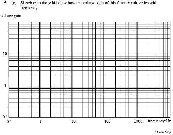
40 Teacher Resource Bank / GCE Electronics / ELEC5 Sample Questions Mark Scheme / Version 1.0 Active Filter (ELE2, Q5, 2008) 5 (a) (i) Allows low frequencies to pass, but blocks high frequencies (ii) The frequency at which the output voltage (gain) is 70% of the maximum output voltage (gain) (b) (c) X c = 1 / 2 π f C X c = 1 / 2 x x 20 x 10-7 X c = 79.6kΩ Gv frequency/hz horizontal line to about 10-20Hz at a gain of 10 diagonal line - decreasing (at about 10 per decade) Total 9 Active Filter (ELE2, Q2, 2005) 2 (a) (i) Low pass filter - a filter that allows low frequencies to pass through with little attenuation, while high frequencies are attenuated (1 mark) (ii) break point frequency - the frequency at which the output voltage is equal to 0.71 of its max value. (1 mark) (b) (i) (non-inverting amplifier. At low frequencies ignore C) =>G v = /10 = 40 (2 marks) 4
41 Teacher Resource Bank / GCE Electronics / ELEC5 Sample Questions Mark Scheme / Version 1.0 (ii) At the cut off frequency X c = R f = 390kΩ C = 1/2πfR = 1/2 π = 163pF (3 marks) (c) 10 6 = frequency x voltage gain => voltage gain = 10 6 / frequency. voltage gain = 10 6 / 2.5 x 10 3 = 400 (2 marks) Total 9 marks Active Filter (ELE5, Q6, 2005) 6 (a) 1 MHz / 4 khz = 250 (2 marks) (b) input bass cut treble cut amplifier output filter filter (3 marks) (c) _ output input + correct resistor circuit correct ratio (5 marks) (d) (i) and (iii) R f _ T C R 1 + (ii) C = 1 / 2 π f o R = 1 / 2 π x 300 x
42 Teacher Resource Bank / GCE Electronics / ELEC5 Sample Questions Mark Scheme / Version 1.0 = 53 nf or 5.3 x 10⁻⁸ F (8 marks) Total 18 marks Amplitude Modulation (ELE5, Q3, 2009) 3 (a) information signal carrier wave AM signal Carrier frequency constant Symmetrical about time axis Amplitude variations: as info sig In phase with info sig (b) (i) Medium wave (ii) (iii) BW = 2 Fi max = = 9kHz = 1188kHz 9 = 132 channels (9 marks) 6
43 Teacher Resource Bank / GCE Electronics / ELEC5 Sample Questions Mark Scheme / Version 1.0 Amplitude Modulation, Half-Wave Dipole (ELE5, Q3, 2008) 3 (a) constant amplitude frequency varies frequency related to info signal FM signal (b) (i) 2 ( ) = 180 khz (ii) = 20 MHz 20 MHz 200 khz = 100 channels (c) (ii) λ = v f = = 3.3m λ 2 = 1.65m less noise, or wide bandwidth, or stereo (any one) Total 10 Amplitude Modulation (ELE5, Q3, 2007) 3 (a) medium waveband (1 mark) (b) amplitude carrier lower side band upper side band inner limits outer limits frequency / khz (5 marks) (c) 6000Hz (1 mark) (Total 7 marks) 7
44 Teacher Resource Bank / GCE Electronics / ELEC5 Sample Questions Mark Scheme / Version 1.0 AM & FM (ELE5, Q2, 2006) 2 (a) amplitude of carrier fluctuation rate of change of carrier amplitude fluctuation (b) amount of frequency deviation rate of change of frequency deviation (2 marks) (2 marks) (c) amplitude carrier 603 khz lower side freq upper side freq khz khz frequency / khz Superhet (ELE5, Q6, 2009) 6 (a) The mixer combines the amplified rf signal with the local oscillator signal producing the required if signal (b) (i) 1 (2π ) MHz (ii) = 454 khz (6 marks) (question total 10 marks) (iii) = MHz (8 marks) 8
45 Teacher Resource Bank / GCE Electronics / ELEC5 Sample Questions Mark Scheme / Version 1.0 Radio Receiver (ELE5, Q1, 2007) 6 (a) 20 / 9 = 2.2μs 1 / khz (3 marks) (b) amplitude phase period time 0 20μs (2 marks) (c) (i) use of f = 1 / 2π LC 1592 khz (ii) or (3 marks) (Total 8 marks) Superhet (ELE5, Q6, 2007) 6 (a) 20 / 9 = 2.2μs 1 / khz (3 marks) (b) amplitude phase period time 0 20μs (2 marks) 9
46 Teacher Resource Bank / GCE Electronics / ELEC5 Sample Questions Mark Scheme / Version 1.0 (c) (i) use of f = 1 / 2π LC 1592 khz (ii) or (3 marks) (Total 8 marks) Tuned Circuit (ELE5, Q4, 2006) 4 (a) (i) selecting required frequency or tuning (ii) improve selectivity or reject unwanted signals better (iii) use of f = 1/ 2π LC 1/ x 10-6 x 300 x MHz (iv) amplitude (impedance) shape frequency labelled axis (6 marks) (b) (i) sensitivity (ii) rf amplifier (2 marks) (question total 8 marks) Radio Receiver, Half-Wave Dipole, Tuned Circuit (ELE5, Q1, 2005) 1 (a) antenna tuned circuit demodulator output device (4 marks) (b) (i) λ = v/f = 3 x 10 8 / 0.6 x 10 6 = 500 m (ii) 500 / 2 = 250 m (iii) L = 1 / 4 π 2 f 2 C = 1 / 40 x 0.36 x x 500 x = 140 μh (6 marks) Total 10 marks 10
47 Teacher Resource Bank / GCE Electronics / ELEC5 Sample Questions Mark Scheme / Version 1.0 Pulse Modulation (ELE5, Q2, 2009) 2 (a) time analogue signal time (b) time analogue signal time 11
48 Teacher Resource Bank / GCE Electronics / ELEC5 Sample Questions Mark Scheme / Version 1.0 (c) time analogue signal time (d) time analogue signal time allow LSB or MSB first (10 marks) 12
49 Teacher Resource Bank / GCE Electronics / ELEC5 Sample Questions Mark Scheme / Version 1.0 Filter, Multiplexer, Sample Rate, Baud Rate (ELE5, Q4, 2009) 4 (a) (i) Low pass/ treble cut (ii) (iii) To prevents signals of frequencies higher than 4kHz aliasing 4 2 = 8kHz (b) (i) Parallel to serial converter (ii) 8 bits 8 khz = 64 kb/s (ii) 12 8 = 96kb/s (7 marks) Pulse Modulation, Filter, Baud Rate (ELE5, Q2, 2008) 2 (a) analogue signal PAM signal any pulse width ok correct amplitudes at sampling points (pulse widths must be constant) PPM signal correct pulse posn narrow, constant width pulses indication of relationship to PWM PWM signal correct varying pulse widths constant amplitudes (b) sample and hold 13
50 Teacher Resource Bank / GCE Electronics / ELEC5 Sample Questions Mark Scheme / Version 1.0 (c) (i) low pass (ii) (iii) (iv) (v) (vi) 10 2 = 5kHz parallel to serial converter bits = 80kbs 1 to tell when data is to be sent, when it is complete, and check if errors have been received = 12, = 120kbs 1 Total 13 Multiplexer (ELE5, Q4, 2008) 4 (a) (b) Q = S.A + S.B (c) Allows two different information sources to be connected to one communication link When S = 1, signal A is connected to the link When S = 0, signal B is connected to the link (d) (i) Time division multiplex (ii) Frequency division multiplex Total 12 14
51 Teacher Resource Bank / GCE Electronics / ELEC5 Sample Questions Mark Scheme / Version 1.0 Pulse Modulation (ELE5, Q4, 2007) 4 (a) PAM signal (2 marks) (b) PWM signal (2 marks) (c) PPM signal (3 marks) 15
52 Teacher Resource Bank / GCE Electronics / ELEC5 Sample Questions Mark Scheme / Version 1.0 (d) 3-bit PCM signal (3 marks) (Total 10 marks) Analogue/Digital Transmission (ELE5, Q5, 2006) 5 (a) examples only (i) (ii) Analogue is more prone to noise Digital signals are encoded Analogue uses superhets, digital uses logic gates Digital is better, noise can be removed Digital is more secure Digital uses simpler circuits (6 marks) (b) TDM FDM (any order) (2 marks) (question total 8 marks) 16
53 Teacher Resource Bank / GCE Electronics / ELEC5 Sample Questions Mark Scheme / Version 1.0 Shift Register, Serial/Parallel Transmission (ELE5, Q7, 2006) 7 (a) Data on D input is sent to Q when clock signal goes high (2 marks) (b) data input clock input D Q CK D Q CK D Q CK D Q CK data output (4 marks) (c) serial only one connection/channel required (2 marks) (question total 8 marks) Mobile Phones (ELE5, Q7, 2005) 7 (a) radio waves (1 mark) (b) (i) time division (ii) 16 x 8 = 128 users (iii) 200 / 8 = 25 khz (5 marks) (c) responding to signal voltage levels in such a way as to lessen the effect of noise schmitt trigger sub system has two threshold levels (4 marks) Total 10 marks 17
54 Teacher Resource Bank / GCE Electronics / ELEC5 Sample Questions Mark Scheme / Version 1.0 Optical Fibre, 555 Monostable, Logic System (ELE5, Q7, 2009) 7 (a) (i) Attenuation of signal (allow causes of attenuation) Dispersion of signal (ii) E.g. security (b) (i) +V s R reset +V s 555 IC discharge threshold output output input trigger C 10nF 0V (ii) C = T 1.1 R nF (c) (i) A B S C D Q (ii) 2 i/p multiplexer When S = 0, B is transmitted When S = 1, A is transmitted (18 marks) 18
55 Teacher Resource Bank / GCE Electronics / ELEC5 Sample Questions Mark Scheme / Version 1.0 Optical Fibre, 555 Astable, Mobile Phones (ELE5, Q7, 2007) 7 (a) low n ray reflecting high n (b) (c) laser diode/led (i) (4 marks) (1 mark) +V s 100k 10kΩ reset +V s 555 IC discharge threshold output to o/p d i trigger 10nF 0V (ii) use of f = 1.44 / R A + 2R B 1200Hz (iii) s (8 marks) (d) (i) radio waves 19
56 Teacher Resource Bank / GCE Electronics / ELEC5 Sample Questions Mark Scheme / Version 1.0 (ii) explanation using: cells frequency re-use channels time division multiplex (5 marks) (Total 18 marks) Optical Fibre, Filter, Sampling (ELE5, Q6, 2006) 6 (a) (i) optic fibre (ii) (iii) (iv) total internal reflection attenuation dispersion (any order) Vr = 12 2 = 10V R = Vr/I = 10/0.01 = 1000Ω (6 marks) (b) (i) _ + (ii) either calculate the reactance of C at 4 khz and show it to be nearly equal to R f, or use of formula for breakpoint frequency. Use of correct formula numerical substitution answer (iii) (iv) 8 khz sampling rate must be at least twice highest signal frequency one sample positive, one negative for highest frequency or diagram, or anti-aliasing (12 marks) (question total 18 marks) 20
hij Teacher Resource Bank GCE Electronics Exemplar Examination Questions ELEC2 Further Electronics
 hij Teacher Resource Bank GCE Electronics Exemplar Examination Questions ELEC2 Further Electronics The Assessment and Qualifications Alliance (AQA) is a company limited by guarantee registered in England
ELE5 (JUN08ELE501) General CertiÞ cate of Education June 2008 Advanced Level Examination. ELECTRONICS Unit 5 Communications Systems
 General CertiÞ cate of Education June 2008 Advanced Level Examination. ELECTRONICS Unit 5 Communications Systems") Surname Other Names For Examiner s Use Centre Number Candidate Number Candidate Signature General CertiÞ cate of Education June 2008 Advanced Level Examination ELECTRONICS Unit 5 Communications Systems
Surname Other Names For Examiner s Use Centre Number Candidate Number Candidate Signature General CertiÞ cate of Education June 2008 Advanced Level Examination ELECTRONICS Unit 5 Communications Systems
Friday 17 June 2016 Morning
 Oxford Cambridge and RSA Friday 17 June 2016 Morning A2 GCE ELECTRONICS F615/01 Communication Systems *2710852624* Candidates answer on the Question Paper. OCR supplied materials: None Other materials
GCE. Electronics. Mark Scheme for June Advanced GCE Unit F615: Communications Systems. Oxford Cambridge and RSA Examinations
 GCE Electronics Advanced GCE Unit F65: Communications Systems Mark Scheme for June 202 Oxford Cambridge and RSA Examinations OCR (Oxford Cambridge and RSA) is a leading UK awarding body, providing a wide
Q.P. Code : [ TURN OVER]
![Q.P. Code : [ TURN OVER]](/thumbs/90/103239233.jpg "Q.P. Code : [ TURN OVER]") Q.P. Code : 587801 8ADF85B2CAF8DDC703193679392A86308ADF85B2CAF8DDC703193679392A86308ADF85B2CAF8DDC703193679392A86308ADF85B2CAF8DDC703193679392A86308ADF85B2CAF8DDC70 6308ADF85B2CAF8DDC703193679392A86308ADF85B2CAF8DDC703193679392A86308ADF85B2CAF8DDC703193679392A86308ADF85B2CAF8DDC703193679392A86308ADF85B2CAF8DDC703
Q.P. Code : 587801 8ADF85B2CAF8DDC703193679392A86308ADF85B2CAF8DDC703193679392A86308ADF85B2CAF8DDC703193679392A86308ADF85B2CAF8DDC703193679392A86308ADF85B2CAF8DDC70 6308ADF85B2CAF8DDC703193679392A86308ADF85B2CAF8DDC703193679392A86308ADF85B2CAF8DDC703193679392A86308ADF85B2CAF8DDC703193679392A86308ADF85B2CAF8DDC703
Amplitude Modulated Systems
 Amplitude Modulated Systems Communication is process of establishing connection between two points for information exchange. Channel refers to medium through which message travels e.g. wires, links, or
Communication Systems Lab
 LAB MANUAL Communication Systems Lab (EE-226-F) Prepared by: Varun Sharma (Lab In-charge) Dayal C. Sati (Faculty In-charge) B R C M CET BAHAL DEPARTMENT OF ELECTRONICS & COMMUNICATION ENGINEERING Page
Chapter-15. Communication systems -1 mark Questions
 Chapter-15 Communication systems -1 mark Questions 1) What are the three main units of a Communication System? 2) What is meant by Bandwidth of transmission? 3) What is a transducer? Give an example. 4)
COMMUNICATION SYSTEMS
 COMMUNICATION SYSTEMS 1. A cordless telephone using separate frequencies for transmission in base and portable units is known as A. duplex arrangement B. half duplex arrangement C. either (a) or (b) D.
Draw in the space below a possible arrangement for the resistor and capacitor. encapsulated components
 1). An encapsulated component is known to consist of a resistor and a capacitor. It has two input terminals and two output terminals. A 5V, 1kHz square wave signal is connected to the input terminals and
S.R.M. Institute of Science & Technology School of Electronics & Communication Engineering
 S.R.M. Institute of Science & Technology School of Electronics & Communication Engineering QUESTION BANK Subject Code : EC314 Subject Name : Communication Engineering Year & Sem : III Year, 6th Sem (EEE)
GCSE Electronics 44301
 GCSE Electronics 4401 Unit 1 Written Paper Mark scheme June 2017 Version: 1.0 Final Mark schemes are prepared by the Lead Assessment Writer and considered, together with the relevant questions, by a panel
Level 6 Graduate Diploma in Engineering Electronics and telecommunications
 9210-116 Level 6 Graduate Diploma in Engineering Electronics and telecommunications Sample Paper You should have the following for this examination one answer book non-programmable calculator pen, pencil,
ELEC2 (JUN15ELEC201) General Certificate of Education Advanced Subsidiary Examination June Further Electronics TOTAL. Time allowed 1 hour
 General Certificate of Education Advanced Subsidiary Examination June Further Electronics TOTAL. Time allowed 1 hour") Centre Number Surname Candidate Number For Examiner s Use Other Names Candidate Signature Examiner s Initials Question Mark Electronics General Certificate of Education Advanced Subsidiary Examination
Centre Number Surname Candidate Number For Examiner s Use Other Names Candidate Signature Examiner s Initials Question Mark Electronics General Certificate of Education Advanced Subsidiary Examination
Data Conversion Circuits & Modulation Techniques. Subhasish Chandra Assistant Professor Department of Physics Institute of Forensic Science, Nagpur
 Data Conversion Circuits & Modulation Techniques Subhasish Chandra Assistant Professor Department of Physics Institute of Forensic Science, Nagpur Data Conversion Circuits 2 Digital systems are being used
A-LEVEL Electronics. ELEC5 Communications Systems Mark scheme June Version: 1.0 Final
 A-LEVEL Electronics ELEC5 Communications Systems scheme 40 June 016 Version: 1.0 Final schemes are prepared by the Lead Assessment Writer and considered, together with the relevant questions, by a panel
Topic Advanced Radio Receivers. Explain that an RF amplifier can be used to improve sensitivity;
 Learning Objectives: At the end of this topic you will be able to; Explain that an RF amplifier can be used to improve sensitivity; Explain that a superheterodyne receiver offers improved selectivity and
Summer 2015 Examination
 Summer 2015 Examination Subject Code: 17445 Model Answer Important Instructions to examiners: 1) The answers should be examined by key words and not as word-to-word as given in the model answer scheme.
GOVERNMENT OF KARNATAKA KARNATAKA STATE PRE-UNIVERSITY EDUCATION EXAMINATION BOARD II YEAR PUC EXAMINATION MARCH-2012 SCHEME OF VALUATION
 GOVERNMENT OF KARNATAKA KARNATAKA STATE PRE-UNIVERSITY EDUCATION EXAMINATION BOARD II YEAR PUC EXAMINATION MARCH-0 SCHEME OF VALUATION Subject Code: 0 Subject: Qn. PART - A 0. Which is the largest of three
GCSE (9-1) WJEC Eduqas GCSE (9-1) in ELECTRONICS ACCREDITED BY OFQUAL DESIGNATED BY QUALIFICATIONS WALES SAMPLE ASSESSMENT MATERIALS
 WJEC Eduqas GCSE (9-1) in ELECTRONICS ACCREDITED BY OFQUAL DESIGNATED BY QUALIFICATIONS WALES SAMPLE ASSESSMENT MATERIALS") GCSE (9-1) WJEC Eduqas GCSE (9-1) in ELECTRONICS ACCREDITED BY OFQUAL DESIGNATED BY QUALIFICATIONS WALES SAMPLE ASSESSMENT MATERIALS Teaching from 2017 For award from 2019 GCSE ELECTRONICS Sample Assessment
GCSE (9-1) WJEC Eduqas GCSE (9-1) in ELECTRONICS ACCREDITED BY OFQUAL DESIGNATED BY QUALIFICATIONS WALES SAMPLE ASSESSMENT MATERIALS Teaching from 2017 For award from 2019 GCSE ELECTRONICS Sample Assessment
B.Tech II Year II Semester (R13) Supplementary Examinations May/June 2017 ANALOG COMMUNICATION SYSTEMS (Electronics and Communication Engineering)
 Supplementary Examinations May/June 2017 ANALOG COMMUNICATION SYSTEMS (Electronics and Communication Engineering)") Code: 13A04404 R13 B.Tech II Year II Semester (R13) Supplementary Examinations May/June 2017 ANALOG COMMUNICATION SYSTEMS (Electronics and Communication Engineering) Time: 3 hours Max. Marks: 70 PART A
Code: 13A04404 R13 B.Tech II Year II Semester (R13) Supplementary Examinations May/June 2017 ANALOG COMMUNICATION SYSTEMS (Electronics and Communication Engineering) Time: 3 hours Max. Marks: 70 PART A
OCR ADVANCED SUBSIDIARY GCE IN ELECTRONICS (3826) OCR ADVANCED GCE IN ELECTRONICS (7826) Specimen Question Papers and Mark Schemes
 OCR ADVANCED GCE IN ELECTRONICS (7826) Specimen Question Papers and Mark Schemes") OCR ADVANCED SUBSIDIARY GCE IN ELECTRONICS (3826) OCR ADVANCED GCE IN ELECTRONICS (7826) Specimen Question Papers and Mark Schemes These specimen assessment materials are designed to accompany the OCR
OCR ADVANCED SUBSIDIARY GCE IN ELECTRONICS (3826) OCR ADVANCED GCE IN ELECTRONICS (7826) Specimen Question Papers and Mark Schemes These specimen assessment materials are designed to accompany the OCR
GOVERNMENT OF KARNATAKA KARNATAKA STATE PRE-UNIVERSITY EDUCATION EXAMINATION BOARD II YEAR PUC EXAMINATION JULY-2012 SCHEME OF VALUATION
 GOVERNMENT OF KARNATAKA KARNATAKA STATE PRE-UNIVERSITY EDUCATION EXAMINATION BOARD II YEAR PUC EXAMINATION JULY-0 SCHEME OF VALUATION Subject Code: 40 Subject: PART - A 0. Which region of the transistor
S.R.M Institute of Science and Technology (Deemed University) Department of Electronics & Communication Engineering
 Department of Electronics & Communication Engineering") S.R.M Institute of Science and Technology (Deemed University) Department of Electronics & Communication Engineering QUESTION BANK Subject Code : EC211 Subject Name : Communication Engineering Year & Sem
S.R.M Institute of Science and Technology (Deemed University) Department of Electronics & Communication Engineering QUESTION BANK Subject Code : EC211 Subject Name : Communication Engineering Year & Sem
 1. COMMUNICATION 10. COMMUNICATION SYSTEMS GIST The sending and receiving of message from one place to another is called communication. Two important forms of communication systems are (i) Analog and (ii)
Electronics (JUN ) General Certificate of Secondary Education June Time allowed 2 hours TOTAL
 General Certificate of Secondary Education June Time allowed 2 hours TOTAL") Centre Number Surname Candidate Number For Examiner s Use Other Names Candidate Signature Examiner s Initials Question Mark General Certificate of Secondary Education June 2012 Electronics 44301 1 2 3
Centre Number Surname Candidate Number For Examiner s Use Other Names Candidate Signature Examiner s Initials Question Mark General Certificate of Secondary Education June 2012 Electronics 44301 1 2 3
AM in frequency domain ( 1 M)
") 1) The Answer should be examined by key words and not as word-to-word as given in the Model Answer scheme. 2) The model Answer and the Answer written by candidate may vary but the examiner may try to assess
1) The Answer should be examined by key words and not as word-to-word as given in the Model Answer scheme. 2) The model Answer and the Answer written by candidate may vary but the examiner may try to assess
GOVERNMENT OF KARNATAKA KARNATAKA STATE PRE-UNIVERSITY EDUCATION EXAMINATION BOARD II YEAR PUC EXAMINATION MARCH-2013 SCHEME OF VALUATION
 GOVERNMENT OF KARNATAKA KARNATAKA STATE PRE-UNIVERSITY EDUCATION EXAMINATION BOARD II YEAR PUC EXAMINATION MARCH-03 SCHEME OF VALUATION Subject Code: 0 Subject: PART - A 0. What does the arrow mark indicate
LIC & COMMUNICATION LAB MANUAL
 LIC & Communication Lab Manual LIC & COMMUNICATION LAB MANUAL FOR V SEMESTER B.E (E& ( E&C) (For private circulation only) NAME: DEPARTMENT OF ELECTRONICS & COMMUNICATION SRI SIDDHARTHA INSTITUTE OF TECHNOLOGY
Massachusetts Institute of Technology MIT
 Massachusetts Institute of Technology MIT Real Time Wireless Electrocardiogram (ECG) Monitoring System Introductory Analog Electronics Laboratory Guilherme K. Kolotelo, Rogers G. Reichert Cambridge, MA
EXPERIMENT WISE VIVA QUESTIONS
 EXPERIMENT WISE VIVA QUESTIONS Pulse Code Modulation: 1. Draw the block diagram of basic digital communication system. How it is different from analog communication system. 2. What are the advantages of
Electronic Instrumentation
 Electronic Instrumentation Project 4: Optical Communication Link 1. Optical Communications 2. Initial Design 3. PSpice Model 4. Final Design 5. Project Report Why use optics? Advantages of optical communication
Electronics Design Laboratory Lecture #10. ECEN 2270 Electronics Design Laboratory
 Electronics Design Laboratory Lecture #10 Electronics Design Laboratory 1 Lessons from Experiment 4 Code debugging: use print statements and serial monitor window Circuit debugging: Re check operation
ANALOG COMMUNICATION
 ANALOG COMMUNICATION TRAINING LAB Analog Communication Training Lab consists of six kits, one each for Modulation (ACL-01), Demodulation (ACL-02), Modulation (ACL-03), Demodulation (ACL-04), Noise power
User Manual. CC1000DK Development Kit
 User Manual Rev. 2.11 CC1000DK Development Kit SWRU058 Page 1 of 24 Table of contents: INTRODUCTION... 3 EVALUATION BOARD... 3 DESCRIPTION... 4 LAYOUT SKETCHES, ASSEMBLY DRAWINGS AND CIRCUIT DIAGRAM...
Code No: R Set No. 1
 Code No: R05220405 Set No. 1 II B.Tech II Semester Regular Examinations, Apr/May 2007 ANALOG COMMUNICATIONS ( Common to Electronics & Communication Engineering and Electronics & Telematics) Time: 3 hours
AC LAB ECE-D ecestudy.wordpress.com
 PART B EXPERIMENT NO: 1 AIM: PULSE AMPLITUDE MODULATION (PAM) & DEMODULATION DATE: To study Pulse Amplitude modulation and demodulation process with relevant waveforms. APPARATUS: 1. Pulse amplitude modulation
SUMMER 15 EXAMINATION
 SUMMER 15 EXAMINATION Subject Code: 17440 Model Answer Important Instructions to examiners: 1) The answers should be examined by key words and not as word-to-word as given in the model answer scheme. 2)
Vinytics Peripherals Pvt. Ltd.
 Vinytics Peripherals Pvt. Ltd. DSB/SSB AM TRANSMITTER MODULATION TRAINER KIT On board variable frequency audio oscillator, carrier frequency generator. On board DSB and SSB modulator, Band pass filter,
How It Works The PPM Radio Control System: Part 1
 Technical M.E.C. Technical Note Note How It Works The PPM Radio Control System: Part 1 Foreword This Technical Note is divided into 3 parts to reduce the file size when downloading each section from the
MODEL ANSWER SUMMER 17 EXAMINATION Subject Title: Linear Integrated Circuit Subject Code:
 MODEL ANSWER SUMMER 17 EXAMINATION Subject Title: Linear Integrated Circuit Subject Code: Important Instructions to examiners: 1) The answers should be examined by key words and not as word-to-word as
Television and video engineering
 Television and video engineering Unit-4 Television Receiver systems Objectives: To learn the requirements of TV receiver Study of monochrome and Colour TV receivers. To learn functions of Tuning circuits
Physical Layer. Networked Systems Architecture 3 Lecture 6
 Physical Layer Networked Systems Architecture 3 Lecture 6 Lecture Outline Physical layer concepts Wired links Unshielded twisted pair, coaxial cable, optical fibre Encoding data onto a wire Wireless links
GCE AS. WJEC Eduqas GCE AS in ELECTRONICS ACCREDITED BY OFQUAL DESIGNATED BY QUALIFICATIONS WALES SAMPLE ASSESSMENT MATERIALS
 GCE AS WJEC Eduqas GCE AS in ELECTRONICS ACCREDITED BY OFQUAL DESIGNATED BY QUALIFICATIONS WALES SAMPLE ASSESSMENT MATERIALS Teaching from 207 For award from 208 AS ELECTRONICS Sample Assessment Materials
DATA SHEET. TDA8415 TV and VTR stereo/dual sound processor with integrated filters and I 2 C-bus control INTEGRATED CIRCUITS
 INTEGRATED CIRCUITS DATA SHEET TV and VTR stereo/dual sound processor with integrated filters and I 2 C-bus control File under Integrated Circuits, IC02 May 1989 with integrated filters and I 2 C-bus control
Outline. Communications Engineering 1
 Outline Introduction Signal, random variable, random process and spectra Analog modulation Analog to digital conversion Digital transmission through baseband channels Signal space representation Optimal
HOW TO UNDERSTAND THE WORKINGS OF RADIO CONTROL
 HOW TO UNDERSTAND THE WORKINGS OF RADIO CONTROL By: Roger Carignan This article resulted from a workshop hosted by a member of our R/C model club, the 495 th R/C Squadron. I was asked to make a presentation
Test Your Understanding
 074 Part 2 Analog Electronics EXEISE POBLEM Ex 5.3: For the switched-capacitor circuit in Figure 5.3b), the parameters are: = 30 pf, 2 = 5pF, and F = 2 pf. The clock frequency is 00 khz. Determine the
Module 8 Theory. dbs AM Detector Ring Modulator Receiver Chain. Functional Blocks Parameters. IRTS Region 4
 Module 8 Theory dbs AM Detector Ring Modulator Receiver Chain Functional Blocks Parameters Decibel (db) The term db or decibel is a relative unit of measurement used frequently in electronic communications
LINEAR IC APPLICATIONS
 1 B.Tech III Year I Semester (R09) Regular & Supplementary Examinations December/January 2013/14 1 (a) Why is R e in an emitter-coupled differential amplifier replaced by a constant current source? (b)
EE12: Laboratory Project (Part-2) AM Transmitter
 AM Transmitter") EE12: Laboratory Project (Part-2) AM Transmitter ECE Department, Tufts University Spring 2008 1 Objective This laboratory exercise is the second part of the EE12 project of building an AM transmitter in
EE12: Laboratory Project (Part-2) AM Transmitter ECE Department, Tufts University Spring 2008 1 Objective This laboratory exercise is the second part of the EE12 project of building an AM transmitter in
Tuned circuits. Introduction - Tuned Circuits
 Tuned circuits Introduction - Tuned Circuits Many communication applications use tuned circuits. These circuits are assembled from passive components (that is, they require no power supply) in such a way
The quality of the transmission signal The characteristics of the transmission medium. Some type of transmission medium is required for transmission:
 Data Transmission The successful transmission of data depends upon two factors: The quality of the transmission signal The characteristics of the transmission medium Some type of transmission medium is
S.E. (Electronics/Electronics and Telecommunication Engg.) (Second Semester) EXAMINATION, 2014 COMMUNICATION THEORY (2008 PATTERN)
 (Second Semester) EXAMINATION, 2014 COMMUNICATION THEORY (2008 PATTERN)") Total No. of Questions 12] [Total No. of Printed Pages 7 Seat No. [4657]-49 S.E. (Electronics/Electronics and Telecommunication Engg.) (Second Semester) EXAMINATION, 2014 COMMUNICATION THEORY (2008 PATTERN)
Total No. of Questions 12] [Total No. of Printed Pages 7 Seat No. [4657]-49 S.E. (Electronics/Electronics and Telecommunication Engg.) (Second Semester) EXAMINATION, 2014 COMMUNICATION THEORY (2008 PATTERN)
ETEK TECHNOLOGY CO., LTD. To Be One of Best Manufacturers at Electronics and Communication Trainers Around the World.
 ETEK TECHNOLOGY CO., LTD To Be One of Best Manufacturers at Electronics and Communication Trainers Around the World. ETEK Products Profile I. Digital and Analog Communications II. RF and Microwave Circuits
SE4 DSP + High Performance Professional Digital Stereo Encoder With DSP Filters
 PCS Electronics www.pcs-electronics.com info@pcs-electronics.com SE4 DSP + High Performance Professional Digital Stereo Encoder With DSP Filters SE4 DSP + without the LCD control module (connects to black
Item no. (Applied. Component) (Credit effect from
 (Credit effect from") AC 29/4/13 Item no. 4.96 UNIVERSITY OF MUMBAI Syllabus for Sem V &VI Program: B..Sc. Course: Radio and Telecommunication (Applied Component) (Credit Based Semester and Grading System with effect from the
AC 29/4/13 Item no. 4.96 UNIVERSITY OF MUMBAI Syllabus for Sem V &VI Program: B..Sc. Course: Radio and Telecommunication (Applied Component) (Credit Based Semester and Grading System with effect from the
EITF25 Internet Techniques and Applications L2: Physical layer. Stefan Höst
 EITF25 Internet Techniques and Applications L2: Physical layer Stefan Höst Data vs signal Data: Static representation of information For storage Signal: Dynamic representation of information For transmission
WIRELESS MICROPHONE. Audio in the ISM band
 WIRELESS MICROPHONE udio in the ISM band Ton Giesberts When the ISM frequency band was made available in Europe for audio applications, Circuit Design, a manufacturer of professional RF modules, decided
HY448 Sample Problems
 HY448 Sample Problems 10 November 2014 These sample problems include the material in the lectures and the guided lab exercises. 1 Part 1 1.1 Combining logarithmic quantities A carrier signal with power
COMMUNICATION SYSTEMS NCERT
 Exemplar Problems Physics Chapter Fifteen COMMUNCATON SYSTEMS MCQ 151 Three waves A, B and C of frequencies 1600 khz, 5 MHz and 60 MHz, respectively are to be transmitted from one place to another Which
Let us consider the following block diagram of a feedback amplifier with input voltage feedback fraction,, be positive i.e. in phase.
 P a g e 2 Contents 1) Oscillators 3 Sinusoidal Oscillators Phase Shift Oscillators 4 Wien Bridge Oscillators 4 Square Wave Generator 5 Triangular Wave Generator Using Square Wave Generator 6 Using Comparator
Department of Electronics & Telecommunication Engg. LAB MANUAL. B.Tech V Semester [ ] (Branch: ETE)
![Department of Electronics & Telecommunication Engg. LAB MANUAL. B.Tech V Semester [ ] (Branch: ETE)](/thumbs/86/93078052.jpg "Department of Electronics & Telecommunication Engg. LAB MANUAL. B.Tech V Semester [ ] (Branch: ETE)") Department of Electronics & Telecommunication Engg. LAB MANUAL SUBJECT:-DIGITAL COMMUNICATION SYSTEM [BTEC-501] B.Tech V Semester [2013-14] (Branch: ETE) KCT COLLEGE OF ENGG & TECH., FATEHGARH PUNJAB TECHNICAL
Department of Electronics & Telecommunication Engg. LAB MANUAL SUBJECT:-DIGITAL COMMUNICATION SYSTEM [BTEC-501] B.Tech V Semester [2013-14] (Branch: ETE) KCT COLLEGE OF ENGG & TECH., FATEHGARH PUNJAB TECHNICAL
SOME PHYSICAL LAYER ISSUES. Lecture Notes 2A
 SOME PHYSICAL LAYER ISSUES Lecture Notes 2A Delays in networks Propagation time or propagation delay, t prop Time required for a signal or waveform to propagate (or move) from one point to another point.
Keywords Internet, LabVIEW, Smart Classroom-cum-Laboratory, Teaching and Learning process of communication.
 Volume 4, Issue 10, October 2014 ISSN: 2277 128X International Journal of Advanced Research in Computer Science and Software Engineering Research Paper Available online at: www.ijarcsse.com Smart Classroom-cum-Laboratory
FM Radio Transmitter & Receiver Modules
 Features Miniature SIL package Fully shielded Data rates up to 128kbits/sec Range up to 300 metres Single supply voltage Industry pin compatible T5-434 Temp range -20 C to +55 C No adjustable components
CSCD 433 Network Programming Fall Lecture 5 Physical Layer Continued
 CSCD 433 Network Programming Fall 2016 Lecture 5 Physical Layer Continued 1 Topics Definitions Analog Transmission of Digital Data Digital Transmission of Analog Data Multiplexing 2 Different Types of
Master Degree in Electronic Engineering
 Master Degree in Electronic Engineering Analog and telecommunication electronic course (ATLCE-01NWM) Miniproject: Baseband signal transmission techniques Name: LI. XINRUI E-mail: s219989@studenti.polito.it
NTE7047 Integrated Circuit TV Color Small Signal Sub System
 NTE7047 Integrated Circuit TV Color Small Signal Sub System Features: Vision IF Amplifier with Synchronous Demodulator Automatic Gain Control (AGC) Detector Suitable for Negative Modulation AGC Tuner Automatic
4/29/2012. General Class Element 3 Course Presentation. Signals and Emissions. SignalSignals and Emissionsissions. Subelement G8
 General Class Element 3 Course Presentation ti ELEMENT 3 SUB ELEMENTS General Licensing Class Subelement G8 Signals and Emissions 2 Exam Questions, 2 Groups G1 Commission s Rules G2 Operating Procedures
Physical Layer. Networked Systems 3 Lecture 5
 Physical Layer Networked Systems 3 Lecture 5 Lecture Outline Physical layer concepts Wired links Unshielded twisted pair, coaxial cable, optical fibre Encoding data onto a wire Wireless links Carrier modulation
Announcement : Wireless Networks Lecture 3: Physical Layer. A Reminder about Prerequisites. Outline. Page 1
 Announcement 18-759: Wireless Networks Lecture 3: Physical Layer Peter Steenkiste Departments of Computer Science and Electrical and Computer Engineering Spring Semester 2010 http://www.cs.cmu.edu/~prs/wirelesss10/
A-level PHYSICS (7408/3BE)
") SPECIMEN MATERIAL A-level PHYSICS (7408/3BE) Paper 3 Section B (Electronics) Specimen 2014 Morning Time allowed: 2 hours Materials For this paper you must have: a pencil a ruler a calculator a data and
SPECIMEN MATERIAL A-level PHYSICS (7408/3BE) Paper 3 Section B (Electronics) Specimen 2014 Morning Time allowed: 2 hours Materials For this paper you must have: a pencil a ruler a calculator a data and
Version 1.0: abc. General Certificate of Education. Applied Science 8771/8773/8776/8779. Medical Physics. Mark Scheme
 Version 1.0: 009 abc General Certificate of Education Applied Science 8771/877/8776/8779 SC08 Medical Physics Mark Scheme 009 examination January series Mark schemes are prepared by the Principal Examiner
HIGH LOW Astable multivibrators HIGH LOW 1:1
 1. Multivibrators A multivibrator circuit oscillates between a HIGH state and a LOW state producing a continuous output. Astable multivibrators generally have an even 50% duty cycle, that is that 50% of
INTRODUCTION TO COMMUNICATION SYSTEMS AND TRANSMISSION MEDIA
 COMM.ENG INTRODUCTION TO COMMUNICATION SYSTEMS AND TRANSMISSION MEDIA 9/9/2017 LECTURES 1 Objectives To give a background on Communication system components and channels (media) A distinction between analogue
Chapter-1: Introduction
 Chapter-1: Introduction The purpose of a Communication System is to transport an information bearing signal from a source to a user destination via a communication channel. MODEL OF A COMMUNICATION SYSTEM
Elements of Communication System Channel Fig: 1: Block Diagram of Communication System Terminology in Communication System
 Content:- Fundamentals of Communication Engineering : Elements of a Communication System, Need of modulation, electromagnetic spectrum and typical applications, Unit V (Communication terminologies in communication
TDA7000 for narrowband FM reception
 TDA7 for narrowband FM reception Author: Author: W.V. Dooremolen INTRODUCTION Today s cordless telephone sets make use of duplex communication with carrier frequencies of about.7mhz and 49MHz. In the base
PRINCIPLES OF COMMUNICATION SYSTEMS. Lecture 1- Introduction Elements, Modulation, Demodulation, Frequency Spectrum
 PRINCIPLES OF COMMUNICATION SYSTEMS Lecture 1- Introduction Elements, Modulation, Demodulation, Frequency Spectrum Topic covered Introduction to subject Elements of Communication system Modulation General
COMM 704: Communication Systems
 COMM 704: Communication Lecture 1: Introduction Dr. Mohamed Abd El Ghany, Mohamed.abdel-ghany@guc.edu.eg Course Objective Give an introduction to the basic concepts of electronic communication systems
DIGITAL ELECTRONICS ANALOG ELECTRONICS
 DIGITAL ELECTRONICS 1. N10 4 Bit Binary Universal shift register. 2. N22- Random Access Memory (16*4). 3. N23- Read Only Memory. 4. N4-R-S/D-T Flip flop, characteristic and comparison. 5. Master Slave
6. has units of bits/second. a. Throughput b. Propagation speed c. Propagation time d. (b)or(c)
or(c)") King Saud University College of Computer and Information Sciences Information Technology Department First Semester 1436/1437 IT224: Networks 1 Sheet# 10 (chapter 3-4-5) Multiple-Choice Questions 1. Before
King Saud University College of Computer and Information Sciences Information Technology Department First Semester 1436/1437 IT224: Networks 1 Sheet# 10 (chapter 3-4-5) Multiple-Choice Questions 1. Before
Power Line Carrier Communication
 IOSR Journal of Electronics and Communication Engineering (IOSR-JECE) e-issn: 2278-2834,p- ISSN: 2278-8735.Volume 9, Issue 2, Ver. II (Mar - Apr. 2014), PP 50-55 Power Line Carrier Communication Dorathe.
Point-to-Point Communications
 Point-to-Point Communications Key Aspects of Communication Voice Mail Tones Alphabet Signals Air Paper Media Language English/Hindi English/Hindi Outline of Point-to-Point Communication 1. Signals basic
Monday 13 June 2016 Afternoon Time allowed: 2 hours
 Please write clearly in block capitals. Centre number Candidate number Surname Forename(s) Candidate signature GCSE ELECTRONICS Unit 1 Written Paper Monday 13 June 2016 Afternoon Time allowed: 2 hours
Course Code: EE-411 Teacher: Engr.Ahmad Bilal Multiple choice & Short Questions notes
 Department of Electrical (POWER) Engineering Swedish College of Engineering & Technology Rahim yar khan Subject: Communication systems Course Code: EE-411 Teacher: Engr.Ahmad Bilal Multiple choice & Short
ELC224 Final Review (12/10/2009) Name:
 Name:") ELC224 Final Review (12/10/2009) Name: Select the correct answer to the problems 1 through 20. 1. A common-emitter amplifier that uses direct coupling is an example of a dc amplifier. 2. The frequency
ELC224 Final Review (12/10/2009) Name: Select the correct answer to the problems 1 through 20. 1. A common-emitter amplifier that uses direct coupling is an example of a dc amplifier. 2. The frequency
SYN500R Datasheet. ( MHz ASK Receiver) Version 1.0
 Version 1.0") SYN500R Datasheet (300-450MHz ASK Receiver) Version 1.0 Contents 1. General Description... 1 2. Features... 1 3. Applications... 1 4. Typical Application... 2 5. Pin Configuration... 2 6. Pin Description...
SYN500R Datasheet (300-450MHz ASK Receiver) Version 1.0 Contents 1. General Description... 1 2. Features... 1 3. Applications... 1 4. Typical Application... 2 5. Pin Configuration... 2 6. Pin Description...
Conventional Paper-II-2011 Part-1A
 Conventional Paper-II-2011 Part-1A 1(a) (b) (c) (d) (e) (f) (g) (h) The purpose of providing dummy coils in the armature of a DC machine is to: (A) Increase voltage induced (B) Decrease the armature resistance
DIGITAL COMMUNICATIONS LAB
 DIGITAL COMMUNICATIONS LAB List of Experiments: 1. PCM Generation and Detection. 2. Differential Pulse Code modulation. 3. Delta modulation. 4. Time Division Multiplexing of 2band Limited Signals. 5. Frequency
Thursday 5 June 2014 Afternoon
 Thursday 5 June 214 Afternoon A2 GCE ELECTRONICS F614/1 Electronic Control Systems *3119659* Candidates answer on the Question Paper. OCR supplied materials: None Other materials required: Scientific calculator
Special-Purpose Operational Amplifier Circuits
 Special-Purpose Operational Amplifier Circuits Instrumentation Amplifier An instrumentation amplifier (IA) is a differential voltagegain device that amplifies the difference between the voltages existing
QUICK START GUIDE FOR DEMONSTRATION CIRCUIT 678A 40MHZ TO 900MHZ DIRECT CONVERSION QUADRATURE DEMODULATOR
 DESCRIPTION QUICK START GUIDE FOR DEMONSTRATION CIRCUIT 678A LT5517 Demonstration circuit 678A is a 40MHz to 900MHz Direct Conversion Quadrature Demodulator featuring the LT5517. The LT 5517 is a direct
Type Ordering Code Package TDA Q67000-A5168 P-DIP-18-5
 Video Modulator for FM-Audio TDA 5666-5 Preliminary Data Bipolar IC Features FM-audio modulator Sync level clamping of video input signal Controlling of peak white value Continuous adjustment of modulation
Exam Booklet. Pulse Circuits
 Exam Booklet Pulse Circuits Pulse Circuits STUDY ASSIGNMENT This booklet contains two examinations for the six lessons entitled Pulse Circuits. The material is intended to provide the last training sought
The steeper the phase shift as a function of frequency φ(ω) the more stable the frequency of oscillation
 the more stable the frequency of oscillation") It should be noted that the frequency of oscillation ω o is determined by the phase characteristics of the feedback loop. the loop oscillates at the frequency for which the phase is zero The steeper the
It should be noted that the frequency of oscillation ω o is determined by the phase characteristics of the feedback loop. the loop oscillates at the frequency for which the phase is zero The steeper the
Exercise 1: RF Stage, Mixer, and IF Filter
 SSB Reception Analog Communications Exercise 1: RF Stage, Mixer, and IF Filter EXERCISE OBJECTIVE DISCUSSION On the circuit board, you will set up the SSB transmitter to transmit a 1000 khz SSB signal
RADIO RECEIVERS ECE 3103 WIRELESS COMMUNICATION SYSTEMS
 RADIO RECEIVERS ECE 3103 WIRELESS COMMUNICATION SYSTEMS FUNCTIONS OF A RADIO RECEIVER The main functions of a radio receiver are: 1. To intercept the RF signal by using the receiver antenna 2. Select the
Data Encoding g(p (part 2)
") Data Encoding g(p (part 2) CSE 3213 Instructor: U.T. Nguyen 10/11/2007 12:44 PM 1 Analog Data, Digital Signals (5.3) 2 1 Analog Data, Digital Signals Digitization Conversion of analog data into digital
Data Encoding g(p (part 2) CSE 3213 Instructor: U.T. Nguyen 10/11/2007 12:44 PM 1 Analog Data, Digital Signals (5.3) 2 1 Analog Data, Digital Signals Digitization Conversion of analog data into digital