MAC 1500 SERVICE MANUAL WARRANTY STATION MAC 1500 STEREO RECEIVER CONTENTS. 2 Chambers St., Binghamton, N.Y
|
|
|
- Claud Newton
- 6 years ago
- Views:
Transcription


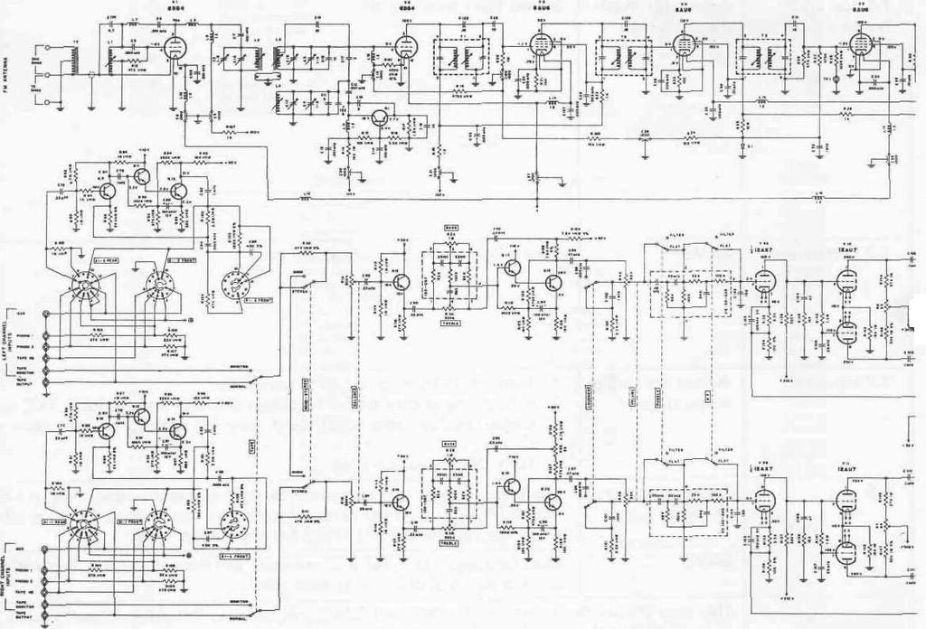
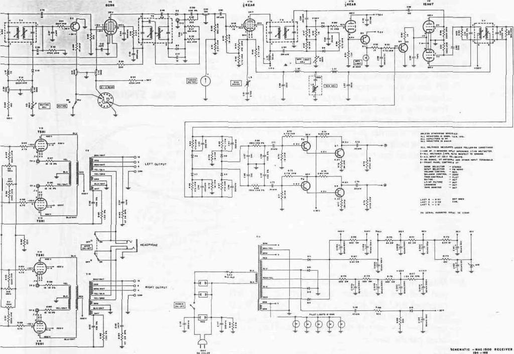
1 MAC 1500 STEREO RECEIVER WARRANTY STATION SERVICE MANUAL CONTENTS INTRODUCTION 1 FM ALIGNMENT CHART 2-3 MULTIPLEX DECODER ALIGNMENT CHART _ 4-5 SCHEMATIC 6-7 TESTS AND ADJUSTMENTS 8 DIAL STRINGING 8 S LIST 9-14 TOP AND BOTTOM VIEWS 15 SPECIFICATIONS 16 BLOCK DIAGRAM 16 McINTOSH AUDIO COMPANY 2 Chambers St., Binghamton, N.Y MAC 1500
2 MAC 1500 STEREO RECEIVER INTRODUCTION All Mclntosh tuners are carefully aligned and tested at the factory using the finest available test equipment. All Mclntosh tuners will meet their published specifications when shipped from the factory. After extensive operation, especially when tubes have been replaced, it may be desirable to realign the timer circuits for best performance. This manual gives complete information on the circuit realignment procedure for the MAC 1500 receiver. The test equipment listed below (or its equivalent) is necessary to properly align a MAC The accuracy of the alignment will be directly related to the accuracy and calibration of the test equipment used. FM Signal Generator (Measurements 210A or equivalent) VTVM Multiplex Generator (RCA WR51A or equivalent) 10.7 MC Generator (Preferably crystal controlled) Oscilloscope (Hewlett -Packard 120B or equivalent) Harmonic Distortion Analyzer (Hewlett-Packard 330B or equivalent) If the necessary test equipment is not available, alignment should not be attempted. You may contact the Mclntosh Customer Service Department for additional information. Customer Service Mclntosh Laboratory, Inc. 2 Chambers Street Binghamton, New York Our telephone number is The direct dial area code is 607 1
 cw VTVM TP#1 Pin 1 of T4 2 3 TP#2 4 105MC 105MC 300 ohm antenna terminals with matching network* 400 cycles 75KC deviation (100% modulation) VTVM")
3 MAC 1500 STEPS TUNER DIAL SETTING FREQ. SIGNAL GENERATOR COUPLING MODULATION TYPE INDICATOR CONNECTED TO 1 Point of no interference and no signal 10.7MC Through external.01 MFD capacitor to mixer grid (pin 4 or 6DS4, V2) cw VTVM TP#1 Pin 1 of T4 2 3 TP# MC 105MC 300 ohm antenna terminals with matching network* 400 cycles 75KC deviation (100% modulation) VTVM connected to TP#2 and. scope connected to L or R tape output MC 105MC 7 8 VTVM connected to TP#2 ; scope and distortion analyzer connected to L or R tape output 9 105MC and 105MC and 50 cps 150KC deviation Approx. 5 microvolts at antenna terminals See note ** at bottom of page cycles 75KC deviation (100% modulation) Scope connected to L or R tape output 11 VTVM connected to TP#1 ; scope and distortion analyzer connected to L or R tape output 2
4 FM ALIGNMENT ADJUST TEST LIMITS REMARKS Top (secondary) and bottom (primary) of T1.T2, T3 Primary and secondary of T4 Secondary (top) of T-5-4 Maximum possible negative voltage Maximum possible negative voltage (should be 20 to 30 volts) Adjust for 0 volts Maximum negative voltage Before making any adjustments, set the controls as follows: a) Input selector switch to FM mono, b) Volume control maximum CCW. c) Muting pot maximum CW. d) Muting OUT. e) Stereo light adjust maximum CW. Shunt to ground the winding not being adjusted. Do this with a.01 MFD capacitor in series with a resistor. Attenuate signal generator until output voltage at TP#1 is less than 1.5 volts with one IF transformer winding shunted. IF transformers have terminal #1 marked with a green dot and are numbered clockwise. _ Muting pot. MUST be maximum CW. The primary (bottom) of T-5 should be adjusted only if a distortion analyzer is available. L-4 Repeat steps 4 and 5 until dial calibration is accurate. C-2, C-3 L-1, L-2, L3 As output increases, attenuate signal generator to keep maximum output at TP#1 to less than 1 volt. Repeat steps 6 and 7 until output is as high as possible. Primary (bottom) of T-5 0. distortion or less Use a strong signal from the FM generator. Adjust T-5 primary for minimum distortion. IF A DISTORTION ANALYZER IS NOT AVAILABLE, OMIT THIS STEP. DO NOT ADJUST T-5 PRIMARY. L-2, C-3 Muting threshold control Minimum tilt IHFM Sensitivity 2.5 microvolts for 3% total noise and distortion Observe direction of tilt of overall response curve at 105MC and. If direction is the same, adjust L-2 at 100MC for minimum tilt. Re-check tilt at and 105MC. If direction is not the same, adjust L-2 (at ) and L-3 (at 105MC) for minimum tilt. Check tilt again at 100MC. With FM generator set for 2.5 microvolts output, place muting control to "IN." Adjust the muting threshold control to the point at which the sine wave on the scope becomes erratic. Step 11 is an overall sensitivity check. It requires a distortion analyzer and FM signal generator with attenuator. With 2.5 microvolts input at the 300 ohm terminals, TP#1 voltage should be.45 volts or more. 3
5 MAC MULTIPLEX STEPS TUNER DIAL SETTING FREQ. SIGNAL GENERATOR COUPLING MODULATION TYPE INDICATOR CONNECTED TO 1 Point of no interference or signal Audio generator set to 67KC 0.5 volts output or less TP#2 Audio VTVM L or R tape output 2 MPX generator with 19KC pilot attenuated to approx. level. ( level is ½ of normal level). 19KC pilot MUST be attenuated for correct alignment DC VTVM Pin 9 of 6EA MC 100MC modulated by MPX generator. 19KC pilot at normal output 300 ohm antenna terminals with matching network. (See * previous page) C 100% modulation (34 KC deviation) modulating left or right only Audio VTVM Audio VTVM and scope Pin 1 or 2 of T-7 L or R tape output Turn off 1 KC audio modulation 8 Tune to a strong mono FM station MPX stereo indicator light on receiver 4
6 DECODER ALIGNMENT ADJUST TEST LIMITS REMARKS 67KC Trap (L-6) Adjust for minimum voltage Stereo light must be on. This is done by adjusting the "MPX Light control, R-12. Adj." T-6 top and bottom; L-5 Adjust for maximum voltage Stereo light must be off. ~ T-7 bottom core Stereo light must be completely on. T-7 top core L-5 MPX light adjust control R-12 Adjust for stable scope display 30db separation or more 1. Turn off 19KC pilot on MPX generator. 2. Adjust upper core of T-7 to obtain a stable and uniform 1 KC signal scope display. This adjustment may be critical, so turn core very slowly. 3. Turn 19KC pilot back on. Modulate left channel and measure right channel output. Adjust L-5 for minimum right channel output (maximum separation). Be sure all test leads are removed from TP#2 for separation tests. Modulate right channel and measure left channel output. Separation in steps 5 and 6 should be at least 30db. This step checks the rejection of 19KC and 38KC frequencies. Residual output should be at least 40db below modulated output. Turn control until light comes on. Then back off just enough to cause the light to go off. Then back off about 1/8 of a turn more. Light should operate ONLY on a MPX signal. 5
7 6
8 7
9 PREAMP/AMP TESTS AND ADJUSTMENTS All adjustments should be made after a minimum of a 10 minute warm-up. 1 Remove the 12AX7 (V-9). 2 Measure the voltage at TP#3. Voltage should be 0.7 volts positive. If it is not 0.7 volts, adjust R-8. 3 Do likewise with TP#4 and R-9, TP#5 and R-10, TP#6 and R Re-insert the 12AX7. 5 Feed a 1 KC signal into AUX. Drive the amp to full 30 watts output. Be sure all controls are set for a flat response. Check to be sure the channels have equal output with equal drive from the audio oscillator. If channels are unbalanced, adjust R-55, This control is found on the left preamp printed circuit board. It will vary the output of the left channel. The preamp cover must be removed to gain access to this control. DIAL STRINGING 6 Measure harmonic distortion at 30 cycles. Adjust R-6 for minimum distortion on the left channel and R-7 for the right. Distortion must be less than 0.. The bottom cover must be removed to adjust these controls. They have blue plastic knobs. 7 Now measure distortion at 2KC and 20KC. Must be less than 0. at full output. 8 Next, feed a signal thru the phono inputs. Check for correct RIAA equalization. 9 Remove all inputs. Check hum and noise on phono 1. Should be at least 60db below rated output. 8
10 MAC 1500 S LIST TUBES V-1 V-2 V-3 V-4 V-5 V-6 V-7 v-8 V-9 V-10 V-11 V-12 V-13 V-14 V-15 USE HF Amplifier Mixer 1st IF Amplifier 2nd IF Amplifier 3rd IF Amplifier, 1st Limiter 4th IF Amplifier, 2nd Limiter 19KC Amplifier, Indicator Control MPX 38KC Oscillator Voltage Amplifier Left Channel Driver Right Channel Driver Left Channel Output Left Channel Output Right Channel Output Right Channel Output TUBE 6DS4 6DS4 6AU6 6AU6 6AU6 6CS6 6EA8 12AU7 12AX7 12AU7 12AU TRANSISTORS USE TRANSISTOR Q-1 Q Q-4 Q-5 Q-6 Q-7 Q-8 Q-9 Q-10 Q-11 Q-12 Q-13 Q-14 Q Q-17 Q-18 Q-19 Q-20 Local Oscillator Control Amplifier MPX Lamp Control Oscillator On-Qff Control Left Channel Audio Amplifier Right Channel Audio Amplifier Left Channel Audio Amplifier Right Channel Audio Amplifier Left Channel Low Level Amplifier Right Channel Low Level Amplifier Left Channel Emitter Follower Right Channel Emitter Follower Left Channel Low Level Amplifier Right Channel Low Level Amplifier Left Channel Emitter Follower Right Channel Emitter Follower Left Channel Emitter Follower Right Channel Emitter Follower Left Channel Voltage Amplifier Right Channel Voltage Amplifier TA2556/ N3638 2N720A 2N720A 2N339IA 2N720A 2N720A DIODES DESCRIPTION DIODE D-1 D-2 D-3 D-4 D-5 D D-8 D-9 D-10 D-11 D-12 D-13 D-14 D-15 D-16 Diode Diode Diode Diode Diode Diode [Matched pair 1N542) Diode (Matched pair 1N542) Diode (Matched pair 1N542] Diode (Matched pair 1N542] Diode (Matched pair 1N542] MA Silicon Rectifier MA Silicon Rectifier MA Silicon Rectifier MA Silicon Rectifier MA Silicon Rectifier MW Zener Rectifier FD100 FD100 FD100 FD100 FD100 IN542 1N542 1N543 IN
11 CONTROLS FUNCTION RESISTANCE R-1 R-2 R-3 R-4 R-5 R-6 R-7 R-8 R-9 R-10 R-11 R-12 R-55 Balance Control Bass Control Treble Control Volume Control Muting Adjust Control Driver Balance Control Driver Balance Control Bias Adjust Control Bias Adjust Control Bias Adjust Control Bias Adjust Control MPX Light Adjust Control Left Channel Gain Control 500K-500K IM- 500K-500K 60K-60K 5K 5K 5K SWITCHES FUNCTION DESCRIPTION S-1 Rotary Switch SS-26 19/32 Trigger Slide Switch SS-50 7/32 Trigger Slide Switch SS-50 19/32 Trigger Slide Switch (S used) Input Selector Muting On -Off Speaker On -Off Stereo/Mono, Tape Monitor, LF and HF Fillers, Loudness TRANSFORMERS FUNCTION T-1 T-2 T-3 T-4 T-5 T-6 T-7 T-8 T-9 T-10 Ml FM-IF FM- IF FM-IF IF (Muting) FM Discriminator 19KC Amplifier 38KC Oscillator Balun Output (Left) Output (Right) Power CAPACITORS DESCRIPTION CAPACITANCE TOLERANCE 10 C-1 C-2 C-3 C-4 C-5 C-6 C-7 C-8 C-9 C-10 C-11 C-13 C-16 C-17 C-18 C-19 C-20 C-21 C-22 C-23 C-24 C-27 C-28 C-29 C-30 Variable FM Trimmer (Ceramic) Trimmer (Ceramic) Trimmer (Glass) Ceramic Feed -Thru Ceramic Feed-Th r u Ceramic Feed-Th ru Ceramic Feed-Thru Ceramic Feed-Thru Ceramic Feed -Thru Ceramic Feed-Thru 1-8 PF 1-8 PF..00FD.00FD 10PF 5PF PF 3PF 10PF.00FD. 10PF.005 MFD.00FD.01 MFD NPO ±.25PF N150 NPO ±.25PF NPO +80 NPO
12 CAPACITORS HEM DESCRIPTION CAPACITANCE VOLTAGE TOLERANCE C-31 C-32 C-33 C-34 C-35 C-36 C-37 C-38 C-40 C-41 C-42 C-43 C-44 C-45 C-46 C-47 C-48 C-49 C-50 C-51 C-52 C-53 C-54 C-55 C-56 C-57 C-58 C-59 C-60 C-61 C-62 C-63 C-64 C-65 C-66 C-67 C-68 C-69 C-70 C-71 C-72 C-73 C-74 C-75 C-76 C-77 C-7B C-79 C-80 C-81 C-82 C-83 C-84 C-85 C-86 C-87 C-88 C-89 C-90 C-91 C-92 C-93 C-94 C-95 C-96 C-97 C-98 C-99 C-100 C-101 C-102 C-103 C-104 C-105 C-106 C-107 C-108 C-109 C-110 C-111 C-112 C-113 Ceramic Feed-Thru Ceramic Feed-Thru Ceramic Feed-Thru Ceramic Feed-Thru Ceramic Feed -Thru Silver Mica Ceramic Disc, Silver Mica Silver Mica Silver Mica Silver Mica Molded Film Molded Film 12PF.PD.01 MFD 15PF.FD.FD 6.8PF 12PF 47PF 100PF.02MFD.0027MFD 100PF.00FD.00FD.02MFD.0012MFD.0012MFD 100MFD _FD 220PF.0047MFD.0047MFD 330PF 330PF 430PF 430PF.01 MFD.01 MFD.22MFD.22MFP 10PF.22MFD.22MFD.FD.FD 100MFD 100MFD.FD.FD.0012MFD.0012MFD 430PF 430PF.22MFD.22MFD.22MFD.22MFD.22MFD.22MFD 100MFD 100MFD.47MFD.7MFD.0015 MFD.0015MFD.047MFD.047MFD 100MFD 100MFO 47PF 47PF.25MFD.25MFD.FD.FD.FD.FD 430 PF 430PF 100V 100V 100V 3V 12V 12V 200V 200V 12V 12V 100V 10CV 3V 3V 400V 400V 600V 600V 600V 600V NPO +80 ±.75PF N150 NPO NPO N470 N NPO N470 N
13 CAPACITORS NO, DESCRIPTION CAPACITANCE VOLTAGE TOLERANCE C-114 C-115 C-116 C-117 C-118 C-119 C-120 C-121 C-122 C-123 C-124 C-125 C-126 C-127 C-128 C-129 C-130 C-131 C-132 C-133 C-134 C-135 Tubular Tubular Tubular Ceramic Feed-Thru Fixed Composition Fixed Composition.FD.FD.47MFD 60-40MFD MFD 50MFD 100MFD 50MFD MFD.18PF.18PF 430PF.02MFD 5PF 1SOPF 150PF 4.7PF 125V 125V 1400V 1400V 200V 500V-500V 450V-300V- 150V 50V 12V 50V 200V-200V- 200V-200V ±.25PF N220 NPO COILS DESCRIPTION VALUE L-1 L-2 L-3 L-4 L-5 L-6 L-7 L-8 L-9 L-10 L-11 L-12 L-13 L-14 L-15 L-16 L-17 L-16 L-19 L-20 L-21 Antenna Coil R.F. Coil Mixer Coil OSC. Coil Peaking Coil Filter Coil Neutralizing Choke Parasitic Choke Peaking Coil Filter Coil Filler Coil 19KC 67KC Trap 2.5 Micro H 1.2 Micro H 1.2 Micro H 1.2 Micro H 1.2 Micro H 1.2 Micro H 1.2 Micro H 1.2 Micro H 1.2 Micro H 1.2 Micro H 75 Micro H 38 Micro H Lo Pass Lo Pass 3% RESISTORS RESISTANCE TOLERANCE WATTAGE R-13 R-14 R-15 R-16 R-17 R-16 R-19 R-20 R-21 R-22 R-23 R-24 R-25 R-26 R-27 R-2S R-29 R-30 R-31 R-32 R-33 R-34 R ohms 15K 3.3K 220 ohms 470 K 100 ohms 100 ohms 10K 10M 470 K 6.8 K 220K 470K 470K 2.2K ½w
14 RESISTORS R-36 R-37 R-38 R-39 R-40 H-41 R-42 R-43 R-44 R-45 R-46 R-47 R-48 R-49 R-50 R-S1 R-52 R-53 R-54 R-60 R-61 R-62 R-63 R-64 R-65 R-66 R-67 R-68 R-69 R-70 R-71 R-72 R-73 R-74 R-75 R-76 R-77 R-78 R-79 R-80 R-81 R-82 R-83 R-84 R-85 R-86 R-87 R-88 R-89 R-90 R-91 R-92 R-93 H-94 R-95 R-96 R-97 R-98 R-99 R-100 R-101 R-102 R-103 R-104 R-105 R-106 R-107 R-108 R-109 R-110 R-111 R-112 R-113 R-114 R-115 R-116 R-117 R-118 R-119 R-120 R-121 R-122 R-123 RESISTANCE 220 ohms 10K 10K 22 K 39K 2.2K IK 470 ohms 4.7K 2.7 K 4.7K 1.2K 4.7K 220K 6.8K 22K 150K 150K 4.7M 4.7M 6.8 K 6.8K 1.8K I.8K 470K 470K 4.7M 4.7M 1.2K 1.2K 27K 27K 220K 220K 680 ohms 630 ohms 15K 15K 3.3M 3.3M I30K 180K 22K 22K 27K 27K 470K 470K 18K 18K TOLERANCE J0% WATTAGE
15 RESISTORS RESISTANCE TOLERANCE WATTAGE R-124 R-125 R-126 R-127 R-128 R-129 R-130 H-131 R-132 R-133 R-134 R-135 R-136 R-137 R-J3S R-139 R-140 R-141 R-142 R-143 R-144 R-145 R-146 R-147 R-148 R-149 R-150 R-151 R-152 R-153 R-151 R-155 R-156 R-157 R-158 R-159 R-160 R-161 R-162 R-163 R-164 R-165 R-166 R-167 R-168 R-169 R-170 R-171 R-172 R-173 R-174 R-175 R-176 R-177 R-178 R-179 R-180 MSI R-182 R-183 R-184 R-185 R-186 R-187 R-188 R-189 R-190 R K 4.7K 7.5K 4.7K 150 ohms 150 ohms 5.6K 5.6K 3.3K 3.3 K 100 ohms 100 ohms 330K 330K 15K 15K 1.2M 1.2M 18K 18K 27K 27K 30K 30K 220K 220K 220K 220K 22K 4.7K 4.7K 4.7K 4.7K 1 5 ohms 1 5 ohms 15 ohms 15 ohms 1.8K 1.8K 47 ohms 47 ohms 2.2M 900 ohms 3.6 K 33 K 33K 6K 6K 8.2K 18K 220 ohms 220 ohms 220 ohms 1.5K 470K 27K 27K 10K 100 ohms 470K 2W 2W 5W 5W 5W 5W 5W 5W 5W 2W MISCELLANEOUS Lamp, MPX #1850 Lamp, Incandescent #1866 Dial Glass Extrusion Glass End Cap Lower Panel Extrusion Upper Panel Extrusion Fuse 3.2 Amp Slo-Blo Tuning Meter Tone Control Module Rumble and HF Module Knob (¼ " without index) Tuning Knob (1 1 / 8 " with index) Volume, Selector, Balance Knob (1 1 / 8 " with index) Bass, Treble Knob (¾" with index) Bass, Treble
 LEFT AND RIGHT PRE AMP PRINTED CIRCUIT BOARDS 6EA8 (V7) TRIMMER COIL RF V1 ANTENNA COIL TUNING CONDENSER COVER V 4 MUTE")

16 MAC 1500 TOP and BOTTOM VIEWS V 15 V 14 V13 BIAS ADJUST CONTROLS V12 V3 V4 OUTPUT TRANSFORMERS LEFT RIGHT POWER TRANSFORMER V10 MIXER V9 V11 V2 COIL TRIMMER OSCILLATOR COIL TRIMMER 12AU7 (V8) LEFT AND RIGHT PRE AMP PRINTED CIRCUIT BOARDS 6EA8 (V7) TRIMMER COIL RF V1 ANTENNA COIL TUNING CONDENSER COVER V 4 MUTE ADJUST CONTROL V12 V13 V14 V15 3RD IF TRANSFORMER 4TH IF TRANSFORMER V5 Q3 2ND IF TRANSFORMER Q4 Q2 2.2K V6 DISCRIMINATOR TRANSFORMER 1ST IF TRANSFORMER 19KC PHASE COIL Q7 Q5 INJECT 10.7 MC SIGNAL HERE Q8 Q6 MPX INPUT (WHITE WIRE; 19 KC TRANSFORMER 67 KC FILTER LOW PASS FILTER 38 KC TRANSFORMER ANTENNA COIL RF COIL MIXER COIL 15

17 FM TUNER SECTION: USABLE SENSITIVITY lot 100% modulation): 2.5uV (I.H.F. Standards) SIGNAL TO NOISE AND HUM RATIO: 65db. HARMONIC DISTORTION: Mono, less than. Stereo, less than.8% DRIFT: less than 25KC FREQUENCY RESPONSE: Flat from 20 cps to 20KC with standard 75 µ second deemphasis and 19KC pilot frequency filter. CAPTURE RATIO: Better than 2.0db. IMAGE REJECTION: Better than 60db. STEREO MULTIPLEX SEPARATION: Better than 30db at 1 KC. SPECIAL FEATURES: a) Automatic stereo switching. b) Muting: IF Injected circuit with at least 50db quieting between stations. c) Antenna inputs for 300 ohm balanced (for twin lead) and 75 ohm unbalanced (for coaxial cable). d) Nuvistor RF amplifier, Nuvistor mixer. e] Four stages of IF amplification, with AGC used to insure that limiting occurs only in the limiter stages. f) Two limiter stages used for exceptional capture ratio and smooth muting operation. g) Multiplex filter and SCA filter, to suppress 19KC and 38KC signal components at least 40db below program and to suppress 67KC SCA by 60db. h) Noise immune logic circuit used to activate MPX stereo light and automatic stereo switching on 19KC stereo pilot only. i) D'Arsonval tuning meter lor accurate center of channel tuning. i) Flywheel tuning for ease of operation and precise tuning. AMPLIFIER SECTION: SPECIFICATIONS POWER OUTPUT: 60 watts continuous, 30 watts per channel, 65 watts total music power (I.H.F. Standards). HARMONIC DISTORTION: less than cps to 20KC, both channels operating at rated output at the same time. INTERMODULATION DISTORTION: Less than 0. for any combination of frequencies from 30 cps to 20KC at rated output (equivalent RMS watts). I.M. decreases as output power is reduced. FREQUENCY RESPONSE: ±0.5db 20 cps to 20KC. (Power amplifier response is 2 cps to 150KC at 3db; power bandwidth is 19 cps to 30KC.) OUTPUT IMPEDANCE: 4, 8, and 16 ohms. Rated output is delivered by any of these impedances. DAMPING FACTOR: Greater than 1 0. INPUT SENSITIVITY AND IMPEDANCE: Tape Head 2.8MV, 1 megohm Phono 1 5.6MV, ohms Phono 2-2.8MV, ohms Aux 400MV, 500K ohms Tape Monilor-400MV, 500K ohms TAPE OUTPUT LEVEL: Tuner-1.2 volts, for other Inputs 400MV at rated sensitivity. HUM AND NOISE: Power Amplifier, 90db High Level Inputs, - 75db Low Level Inputs, 60db TONE CONTROL RANGE: Bass control + 1 5db to - 1 8db at 50 cps. Treble control + 1 5db to db at 10KC. L.F. and H.F. FILTER: L.F. filter, cutoff frequency = 50 cps, attenuation rate 1 2db per octave H.F. Filler, cutoff frequency = 5KC. attenuation rale = 1 2db per octave SPECIAL FEATURES: a) Loudness control for full fidelity listening levels. b) Tape monitor switch for listening to recorded tope program white recording. c) Tone controls are "clutched" for tracking operation of left and right channels or independent operation. d) Headphone output fed from special tap on output transformer for maximum signal to noise ratio. Speakers may be automatically muted when headphone plug is inserted, by use of rear mounted switch. e) Silicon transistors used in all preamplifier stages for low noise and hum free operation. f) High quality epoxy circuit boards for reliable long life performance. g) High quality conservatively operated components ore used throughout for long life. h) Zener regulated power supply is used for critical circuits. i) Equalization and tone control circuits are feedback type for lowest distortion and greatest accuracy. MISCELLANEOUS FINISH: Gold anodized panel and knobs, black finished chassis. DIMENSIONS: 16" wide, 5½" high, 16" deep. WEIGHT: 40 lbs., shipping weight 54 Ibs. POWER CONSUMPTION: 180 watts, 120 volts, 60 cps. TRANSISTOR AND TUBE COMPLEMENT: 19 silicon transistors 1 germanium transistor 15 tubes 1 6 diodes, rectifier, and zener diode BLOCK DIAGRAM 16 MAC 1500 STEREO RECEIVER BLOCK DIAGRAM
18 MclNTOSH AUDIO COMPANY 2 Chambers St., Binghamton, N.Y Made In U.S.A. Phong Area Code Design subject to change without notice. Printed in U.S.A BE062003
MA 5100 SERVICE INFORMATION PREAMP - AMPLIFIER. MclNTOSH LABORATORY INC. 2 CHAMBERS STREET BINGHAMTON, NEW YORK STARTING WITH SERIAL NO.
 PREAMP - AMPLIFIER SERVICE INFORMATION STARTING WITH SERIAL NO. 21HOO MclNTOSH LABORATORY INC. 2 CHAMBERS STREET BINGHAMTON, NEW YORK ELECTRICAL SPECIFICATIONS Power Output: 90 watts RMS continuous, 45
MR65 OWNER'S MANUAL STEREO FM TUNER ISSUE NO. 2. Reading Time 30 Minutes Price $1.25
 STEREO FM TUNER MR65 TABLE OF CONTENTS GENERAL DESCRIPTION 1 TECHNICAL DESCRIPTION 1 FRONT PANEL FACILITIES 2 Dial Scale 2 Meters 2 Volume Control 2 Mode Selector 2 Auto. Freq. Control 3 Muting 3 BACK
MASTR II AUXILIARY RECEIVER 19D417546G7 & G8 & ANTENNA MATCHING UNITS 19C321150G1-G2. Maintenance Manual LBI-30766L. Mobile Communications
 L Mobile Communications MASTR II AUXILIARY RECEIVER 19D417546G7 & G8 & ANTENNA MATCHING UNITS 19C321150G1-G2 Printed in U.S.A Maintenance Manual TABLE OF CONTENTS Page SPECIFICATIONS.....................................................
INCORPORATED. SERVICE PUBLICATIONS DEPARTMENT Entertainment Products Group - Sylvania Electric Products Inc Ellicott Street - Batavia, N.Y.
 GTE sylvania INCORPORATED FACTORY PREPARED TECHNICAL SERVICE DATA STEREO HI-FI BULLETIN: R49-3 MODEL: CR280 SERVICE PUBLICATIONS DEPARTMENT Entertainment Products Group - Sylvania Electric Products Inc.-
UNITED MOTORS SERVICE D IV ISIO N OF GENERAL M O TO RS C O R P O R A T IO N. General Offices - Detroit AUTO RADIO BULLETIN
 UNITED MOTORS SERVICE D IV ISIO N OF GENERAL M O TO RS C O R P O R A T IO N General Offices - Detroit AUTO RADIO BULLETIN Bulletin 6D-855 Date 11-1-54 Page 1 FIRST ISSUE SUBJECT: SERVICE INSTRUCTIONS -
MC24O OWNER'S MANUAL STEREO POWER AMPLIFIER CONTENTS
 STEREO POWER AMPLIFIER MC24O CONTENTS GENERAL DESCRIPTION 1 TECHNICAL DESCRIPTION 1 PANEL FACILITIES 4 INSTALLATION 5 CONNECTIONS 5 Input Stereo 5 Input Twin Amp 5 Input Mono 6 Output Stereo or Twin Amp
hallicrafters PERFORMANCE SPECIFICATIONS MODEL: SR-2000 LATEST REVISION: 18 JAN 66 Code ident # Specification #
 hallicrafters PERFORMANCE SPECIFICATIONS MODEL: SR-2000 LATEST REVISION: 18 JAN 66 Code ident # 26916 Specification # 093-002154 I. GENERAL A. Power input 117V 50-60 cycles from a source capable of delivering
MR66 STEREO TUNER TABLE OF CONTENTS
 MR66 STEREO TUNER MR66 TABLE OF CONTENTS INTRODUCTION TECHNICAL DESCRIPTION FRONT PANEL INFORMATION BACK PANEL INFORMATION INSTALLATION CONNECTING Monophonic FM and AM Stereophonic FM and AM Stereophonic
MC2301. Features and Benefits. Promotional Highlights TUBE POWER AMPLIFIER MCINTOSH LABORATORY INC., 2 CHAMBERS STREET, BINGHAMTON, NEW YORK 13903
 MC2301 Product Preview Page 1 McIntosh Laboratory, Inc., Binghamton, NY 13903 Design Engineering Department PRODUCT PREVIEW MC2301 TUBE POWER AMPLIFIER Project 1336 Promotional Highlights 300 Watts Mono
FREQUENCY AGILE FM MODULATOR INSTRUCTION BOOK IB
 FMT615C FREQUENCY AGILE FM MODULATOR INSTRUCTION BOOK IB1215-02 TABLE OF CONTENTS SECTION SUBJECT 1.0 Introduction 2.0 Installation & Operating Instructions 3.0 Specification 4.0 Functional Description
HF Receivers, Part 2
 HF Receivers, Part 2 Superhet building blocks: AM, SSB/CW, FM receivers Adam Farson VA7OJ View an excellent tutorial on receivers NSARC HF Operators HF Receivers 2 1 The RF Amplifier (Preamp)! Typical
OPERATING THE SYLVANIA STEREO RECEIVER RS4743
 OPERATING THE SYLVANIA STEREO RECEIVER RS3 TABLE OF CONTENTS Page Introduction 2 Accessory Components 3 Initial Hook-Up Connecting Accessory Components Antenna Connections Jacks Aux Jacks Tape Jacks Pre-Amp
UNITED MOTORS SERVICE. DIVISION OF GENERAL MOTORS CORPORATION General Offices - Detroit AUTO RADIO BULLETIN
 UNITED MOTORS SERVICE DIVISION OF GENERAL MOTORS CORPORATION General Offices - Detroit AUTO RADIO BULLETIN Bulletin 6D-848 Chevrolet 986515 Page 1 SUBJECT: SERVICE INSTRUCTIONS CHEVROLET CUSTOM DELUXE
Frequency range: BAND RANGE MHz MHz
 INSTRUCTION SHEET NO. 20 POWER-MITE PM3 and PM3A DESCRIPTION The Power-Mite 3 and 3A are self-contained CW transceivers covering 40 and 20 meters. The receiver is compromised of a variable oscillator operating
Registration 3. Owners Record Setup 4. Unit Connections 6. Front Panel Controls 8. Remote Control 9. Unit Care Technology 10. Designer s Note 12.
 Registration 3. Owners Record Setup 4. Unit Connections 6. Front Panel Controls 8. Remote Control 9. Unit Care Technology 10. Designer s Note 12. Specifications 2 The model and serial numbers are located
FEATURES AND BENEFITS PROMOTIONAL HIGHLIGHTS MCINTOSH LABORATORY INC., 2 CHAMBERS STREET, BINGHAMTON, NEW YORK MC206 Product Preview Page 1
 MC206 Product Preview Page 1 McIntosh Laboratory, Inc., Binghamton, NY 13903 Design Engineering Department PRODUCT BRIEF MC206 SIX CHANNEL POWER AMPLIFIER Project 1160 Contents Promotional Highlights 1
51J-4 COMMUNICATIONS RECEIVER
 51J-4 COMMUNICATIONS RECEIVER Transcribed from 520-5014-00 August 15, 1954 GENERAL DESCRIPTION The Collins 51J-4 Receiver is designed for communication applications where stability and dial accuracy of
 file:///c /BoatAnchors/Hammarlund/HQ170A/HQ170SVC.TXT Dear OM: This form is being prepared to provide prompt attention to a complaint as a result of trouble that may be experienced in the field. In addition
How to make audio measurements on stereo receivers and amplifiers
 How to make audio measurements on stereo receivers and amplifiers HOW TO INCREASE YOUR SALES Many dealers are using performance tests on the sales floor to sell customers up to a more expensive item. Such
UNITED MOTORS SERVICE AUTO RADIO BULLETIN
 UNITED MOTORS SERVICE DIVISION OF GENERAL MOTORS CORPORATION General Offices - Detroit AUTO RADIO BULLETIN Bulletin 6D-854 Date 11-1-54 Page 1 FIRST ISSUE GENERAL SUBJECT: SERVICE INSTRUCTIONS - 12V CHEVROLET
D ELCO. electronic parts AUTO RADIO BULLETIN. Connect Signal Generator to
 D ELCO electronic parts AUTO RADIO BULLETIN Bulletin 6D-864 Date 10-15-56 Page 1 FIRST ISSUE SUBJECT: SERVICE INSTRUCTIONS - CHEVROLET CUSTOM DELUXE WITH PUSH BUTTON TUNING - MODEL 987575 GENERAL M O U
30 Watt Audio Power Amplifier
 30 Watt Audio Power Amplifier Including Preamp, Tone Controls, Reg dc Power Supply, 18 Watt into 8 Ohm - 30W into 4 Ohm loads Amplifier Section Circuit diagram: Audio Power Amplifier Circuit Diagram This
HOM rev. new Heathkit of the Month #74: by Bob Eckweiler, AF6C STEREO HI-FI EQUIPMENT. Heath of the Month #74 - Model Description
 Heathkit of the Month #74: by Bob Eckweiler, AF6C STEREO HI-FI EQUIPMENT Heathkit AA-14 Solid-State Stereo Amplifier Introduction: Heathkit of the Month #63 covered the AJ-14 Stereo FM Tuner. For many
E-200D ALIGNMENT. See the end of the procedure for the location of the calibration points. EQUIPMENT REQUIRED
 E-200D ALIGNMENT NOTE: This is not an official B&K alignment procedure. This procedure was created by experimenting with an E-200D. However when this procedure is followed, the resulting calibration should
MFJ-752C SIGNAL ENHANCER II
 MFJ-752C SIGNAL ENHANCER II INTRODUCTION The improved MFJ-752C SIGNAL ENHANCER II is comprised of two tunable audio filtering systems designed to clarity and remove interfering signals from both voice
KWM-2/2A Transceiver THE COLLINS KWM-2/2A TRANSCEIVER
 KWM-2/2A Transceiver Click the photo to see a larger photo Click "Back" button on browser to return Courtesy of Norm - WA3KEY THE COLLINS KWM-2/2A TRANSCEIVER Unmatched for versatility, dependability and
Restoration Performance Report
 Restoration Performance Report Report Date: July 15, 2015 Manufacturer: Fisher Model: 500-C Receiver Special Notes: Full Gold Level Restoration service completed. Chassis ultrasonically cleaned. All coupling
Professional Equalizer-Preamp Suitable for Home Use
 A combined Professional Equalizer-Preamp Suitable for Home Use KENNETH W. BETSH* Designed originally for broadcast-station use, this preamplifier can be adapted to any installation where it would be desirable
TRANSISTORIZED, POWER SUPPLY HIGH-LEVEL PUSH-PULL MODULATION DUAL CONVERSION RECEIVER "PASS BAND" FINE TUNE CONTROL 24 CHANNEL TURRETUNER
 TRANSISTORIZED, POWER SUPPLY HIGH-LEVEL PUSH-PULL MODULATION DUAL CONVERSION RECEIVER "PASS BAND" FINE TUNE CONTROL 24 CHANNEL TURRETUNER I GENERAL SUPER MC-ll PDF d By Woody @ http://www.cbgazette.com
Contents. The Mclntosh compact Family MR 500 DIGITAL FM TUNER
 Contents SERVICE CONTRACT INFORMATION 1 INTRODUCTION 2 INSTALLATION 3, 4 BACK PANEL CONNECTIONS AND CONTROLS 5, 6 USING THE FRONT PANEL CONTROLS 7, 8 HOW THE CIRCUITS WORK 9, 10 PERFORMANCE LIMITS 11 PERFORMANCE
MASTR II BASE STATION MHz RECEIVER IF/AUDIO/SQUELCH & RF ASSEMBLY (25 khz/12.5 khz CHANNEL SPACING) Maintenance Manual LBI-38506A
 Maintenance Manual LBI-38506A") A Mobile Communications MASTR II BASE STATION 806-824 MHz RECEIVER IF/AUDIO/SQUELCH & RF ASSEMBLY (25 khz/12.5 khz CHANNEL SPACING) TABLE OF CONTENTS RF ASSEMBLY, MIXER AND IF FILTER BOARD...... LBI-30482
A Mobile Communications MASTR II BASE STATION 806-824 MHz RECEIVER IF/AUDIO/SQUELCH & RF ASSEMBLY (25 khz/12.5 khz CHANNEL SPACING) TABLE OF CONTENTS RF ASSEMBLY, MIXER AND IF FILTER BOARD...... LBI-30482
LBI-30398N. MAINTENANCE MANUAL MHz PHASE LOCK LOOP EXCITER 19D423249G1 & G2 DESCRIPTION TABLE OF CONTENTS. Page. DESCRIPTION...
 MAINTENANCE MANUAL 138-174 MHz PHASE LOCK LOOP EXCITER 19D423249G1 & G2 LBI-30398N TABLE OF CONTENTS DESCRIPTION...Front Cover CIRCUIT ANALYSIS... 1 MODIFICATION INSTRUCTIONS... 4 PARTS LIST AND PRODUCTION
INSTRUCTION BOOK FOR MODEL G-187 SPECIAL PURPOSE RECEIVER
 INSTRUCTION BOOK FOR MODEL G-187 SPECIAL PURPOSE RECEIVER LTV - Electrosystems, Inc. (A Subsidiary of Ling-Temco-Vought) TEMCO Aerosystems Division P.O. Box 1056 Greenville, Texas 75402 WARNING This equipment
LeMay Audio Products. MK-I Preamplifier Users Manual John P. LeMay All Rights Reserved Rev A
 LeMay Audio Products MK-I Preamplifier Users Manual 2008 John P. LeMay All Rights Reserved Rev A 08.12.24 Congratulations on purchasing one of the world s finest professional instrument preamplifiers!
MciNTOSH MODEL Me-30
 INSTRUCTION MANUAL MciNTOSH MODEL Me-30 30 WATT POWER AMPLIFIER Type A-116B Serial # 15329 and Over MciNTOSH LABORATORY, INC 2 Chambers St. Binghamton, N. Y. U.S.A. 1.5M 757 HPB ELECTRICAL AND MECHANICAL
ERICSSONZ LBI-30398P. MAINTENANCE MANUAL MHz PHASE LOCKED LOOP EXCITER 19D423249G1 & G2 DESCRIPTION TABLE OF CONTENTS
 MAINTENANCE MANUAL 138-174 MHz PHASE LOCKED LOOP EXCITER 19D423249G1 & G2 TABLE OF CONTENTS Page DESCRIPTION... Front Cover CIRCUIT ANALYSIS...1 MODIFICATION INSTRUCTIONS...4 PARTS LIST...5 PRODUCTION
Building a Bitx20 Version 3
 Building a Bitx20 Version 3 The board can be broken into sections and then built and tested one section at a time. This will make troubleshooting easier as any problems will be confined to one small section.
ERICSSONZ LBI-39123A. MAINTENANCE MANUAL FOR 21.4 MHz RECEIVER IF MODULE 12.5/25 khz CHANNEL SPACING 19D902783G7 DESCRIPTION TABLE OF CONTENTS
 A MAINTENANCE MANUAL FOR 21.4 MHz 12.5/25 khz CHANNEL SPACING 19D902783G7 TABLE OF CONTENTS Page DESCRIPTION............................................ Front Cover GENERAL SPECIFICATIONS....................................
SPECIFICATIONS: Subcarrier Frequency 5.5MHz adjustable, FM Modulated +/- 50KHz. 2nd 11MHz >40dB down from 5.5MHz
 Mini-kits AUDIO / SUBCARRIER KIT EME75 Version4 SPECIFICATIONS: Subcarrier Frequency 5.5MHz adjustable, FM Modulated +/- 50KHz Subcarrier Output 1.5v p-p Output @ 5.5MHz DESCRIPTION & FEATURES: The Notes
LL1.1 Signature preamplifier
 LL1.1 Signature preamplifier The monaural line level preamplifier model LL1.1 Signature is a direct replacement of the LL1 Signature which has been the ultimate statement of perfection among the line level
UNITED MOTORS SERVICE D IV ISIO N OF GENERAL M O TO RS C O R P O R A T IO N. General Offices - Detroit AUTO RADIO BULLETIN
 UNITED MOTORS SERVICE D IV ISIO N OF GENERAL M O TO RS C O R P O R A T IO N General Offices - Detroit AUTO RADIO BULLETIN Page 1 FIRST ISSUE SUBJECT: SERVICE INSTRUCTIONS - CHEVROLET TRUCK MODEL 987187
The ROSE 80 CW Transceiver (Part 1 of 3)
") Build a 5 watt, 80 meter QRP CW Transceiver!!! Page 1 of 10 The ROSE 80 CW Transceiver (Part 1 of 3) Build a 5 watt, 80 meter QRP CW Transceiver!!! (Designed by N1HFX) A great deal of interest has been
Build a 5 watt, 80 meter QRP CW Transceiver!!! Page 1 of 10 The ROSE 80 CW Transceiver (Part 1 of 3) Build a 5 watt, 80 meter QRP CW Transceiver!!! (Designed by N1HFX) A great deal of interest has been
THE MclNTOSH MC 2255 SOLID STATE STEREO POWER AMPLIFIER
 THE MclNTOSH MC 2255 SOLID STATE STEREO POWER AMPLIFIER Reading Time: 31 Minutes Price $2.00 VARIOUS REGULATORY AGENCIES REQUIRE THAT WE BRING THE FOLLOWING INFORMATION TO YOUR ATTENTION. PLEASE READ IT
Contents. 1. Essential Electronics 1. Preface Acknowledgements
 Contents Preface Acknowledgements ix xi 1. Essential Electronics 1 1.1: Current 2 1.2: Voltage 5 1.3: Power 6 1.4: Signals and Averages 7 1.4.1: Mean Average 7 1.4.2: Rectified Average 8 1.4.3: RMS Average
Figure 2 shows the actual schematic for the power supply and one channel.
 Pass Laboratories Aleph 3 Service Manual rev 0 2/1/96 Aleph 3 Service Manual. The Aleph 3 is a stereo 30 watt per channel audio power amplifier which operates in single-ended class A mode. The Aleph 3
The Aleph 2 is a monoblock 100 watt audio power amplifier which operates in single-ended class A mode.
 Pass Laboratories Aleph 2 Service Manual Rev 0 2/1/96 Aleph 2 Service Manual. The Aleph 2 is a monoblock 100 watt audio power amplifier which operates in single-ended class A mode. The Aleph 2 has only
.2 Section Waste Management and Disposal..4 Section Electrical General Requirements.
 Issued 2006/08/01 Section 16724 Public Address System Page 1 of 8 PART 1 GENERAL 1.1 RELATED SECTIONS.1 Section 01330 Submittal Procedures..2 Section 01355 Waste Management and Disposal..3 Section 01780
TOA 500 SERIES MIXER POWER AMPLIFIER
 TOA 500 SERIES MIXER POWER AMPLIFIER Operation Instruction Manual A-503A A-506A A-512A Features General Description 1. High quality design and construction. 2. Full frequency response: 50-15,000Hz, ±3dB.
MC2505 STEREO POWER AMPLIFIER MC25O5 SOLID STATE PRICE $1.25
 MC2505 SOLID STATE STEREO POWER AMPLIFIER MC25O5 PRICE $1.25 The Mclntosh "will to perfection" requires that we probe constantly into the unknown to bring the performance of our electronic equipment closer
Kaskode One Phono Preamplifier Owner s Manual
 Kaskode One Phono Preamplifier Owner s Manual www.bandwidthaudio.com sales@bandwidthaudio.com WARNING Configuration of the Kaskode One will require removing the cover of the unit. Before removing the cover
Copyright 2016, R. Eckweiler & OCARC, Inc. Page 1 of 7
 Heathkit of the Month: by Bob Eckweiler, AF6C ELECTRONIC TEST EQUIPMENT Heathkit IM-38 AC Vacuum Tube Voltmeter (VTVM). Introduction: Back in March of 2013 Heathkit of the Month #47 discussed the Heathkit
TOA NEW 900 SERIES MIXER PREAMPLIFIER M-900A
 Operation Instruction Manual TOA NEW 900 SERIES MIXER PREAMPLIFIER M-900A Features General Description 1 6-channel mixer preamplifier 2 Wide frequency response; 20 20,000Hz, ±1dB 3 Low distortion and noise
THE McINTOSH MR 78 SOLID STATE FM/FM STEREO TUNER
 THE McINTOSH MR 78 SOLID STATE FM/FM STEREO TUNER Reading Time 32 Minutes Price $1.25 Your MR 78 FM/FM Stereo Tuner will give you many years of pleasant and satisfactory performance. If you have any questions
MFJ SIGNAL ENHANCER II
 MFJ SIGNAL ENHANCER II Model MFJ-752D INSTRUCTION MANUAL CAUTION: Read All Instruction Before Operating Equipment MFJ ENTERPRISES, INC. P.O. BOX 494, MISSISSIPPI STATE, MS 39762, USA 925-0037D-752D-REV
The Aleph 5 is a stereo 60 watt audio power amplifier which operates in single-ended class A mode.
 Pass Laboratories Aleph 5 Service Manual Rev 0 9/20/96 Aleph 5 Service Manual. The Aleph 5 is a stereo 60 watt audio power amplifier which operates in single-ended class A mode. The Aleph 5 has only two
POWER AMPLIFIER SERVICE MANUAL CONTENTS
 POWER LIFIER CONTENTS Performance Specifications... 2 Notes... 2 Rear Panel... 3 Section Location... 4 Block Diagram... 5-6 Interconnection Diagram... 7-8 Input PCB and Schematic... 9-10 Main PCB and Schematic...
MODEL AF200A: FM, FM/SCA RECEIVER/MONITOR OPERATION MANUAL
 MODEL AF200A: FM, FM/SCA RECEIVER/MONITOR OPERATION MANUAL THE AF200A IS AN FM AND FM/SCA PROFESSIONAL STYLE RECEIVER/ MONITOR. IT S MANY APPLICATIONS INCLUDE STATION MONITORING AND EAS MONITORING. The
AM/FM TUNER INCLUDING TM1 TUNER MODULE OPTION
 AM/FM TUNER INCLUDING TM1 TUNER MODULE OPTION CONTENTS Performance Specifications... 2 Notes... 2 Rear Panel... 3 Section Location... 3 Block Diagram... 4 Interconnection Diagram... 5-6 Power Supply Schematic
WESTREX RA-1712 PHOTOGRAPHIC SOUND RECORD ELECTRONICS
 INTRODUCTION The RA-1712 solid state Record Electronics is an integrated system for recording photographic sound tracks on a Westrex photographic sound recorder. It accepts a 600Ω input signal level from
ERICSSONZ LBI-39123C. MAINTENANCE MANUAL FOR 21.4 MHz RECEIVER IF MODULE 12.5/25 khz CHANNEL SPACING 19D902783G7 & G11 DESCRIPTION TABLE OF CONTENTS
 MAINTENANCE MANUAL FOR 21.4 MHz 12.5/25 khz CHANNEL SPACING 19D902783G7 & G11 TABLE OF CONTENTS Page DESCRIPTION............................................ Front Cover GENERAL SPECIFICATIONS....................................
USER MANUAL QSM-606AZ QSM-612AZ QSM-624AZ MIXER AMPLIFIER
 USER MANUAL QSM-606AZ QSM-612AZ QSM-624AZ MIXER AMPLIFIER WARNING: THIS APPLIANCE MUST BE EARTHED IMPORTANT The wires in the mains lead are coloured In accordance with the following code: Green and Yellow:
HAMTRONICS R451 UHF FM RECEIVER: INSTALLATION, OPERATION, & MAINTENANCE
 HAMTRONICS R451 UHF FM RECEIVER: INSTALLATION, OPERATION, & MAINTENANCE FUNCTIONAL DESCRIPTION. The R451 is a premium, commercial- grade single-channel uhf fm receiver. It features a GaAs FET rf amplifier
HAMTRONICS TB901 FM EXCITER INSTALLATION, OPERATION, & MAINTENANCE
 HAMTRONICS TB901 FM EXCITER INSTALLATION, OPERATION, & MAINTENANCE GENERAL INFORMATION. The TB901 is a single-channel low power fm transmitter (exciter) designed to provide 300-600 milliwatts continuous
ERICSSONZ LBI-39123D. MAINTENANCE MANUAL FOR 21.4 MHz RECEIVER IF MODULE 12.5/25 khz CHANNEL SPACING 19D902783G7 & G11 DESCRIPTION
 MAINTENANCE MANUAL FOR 21.4 MHz RECEIVER IF MODULE 12.5/25 khz CHANNEL SPACING 19D902783G7 & G11 TABLE OF CONTENTS Page DESCRIPTION............................................ Front Cover GENERAL SPECIFICATIONS....................................
Hendricks QRP Kits BITX20A to BITX17A Conversion Instructions
 Hendricks QRP Kits BITX20A to BITX17A Conversion Instructions 30 November 2008 Converting your BITX20A Kit to a BITX17A Kit is not all that complex. It only requires that you change crystals and some resonance
Operation Manual. Model SG Elenco Precision Wide Band Signal Generator
 99 Washington Street Melrose, MA 02176 Phone 781-665-1400 Toll Free 1-800-517-8431 Visit us at www.testequipmentdepot.com Elenco Precision Wide Band Signal Generator Model SG-9000 Operation Manual CONTENTS
HAMTRONICS R144 VHF FM RECEIVER, REV. 4/94: INSTALLATION AND MAINTENANCE
 HAMTRONICS R144 VHF FM RECEIVER, REV. 4/94: INSTALLATION AND MAINTENANCE FUNCTIONAL DESCRIPTION. The R144 is a premium commercial grade single-channel vhf fm receiver. It features a helical resonator front
TOA NEW 900 SERIES MIXER POWER AMPLIFIER A-901A. General Description. TOA Corporation. Operation Instruction Manual
 Operation Instruction Manual TOA NEW 900 SERIES MIXER POWER AMPLIFIER A-901A Features 1 3-channel mixer power amplifier 2 Wide frequency response; 20 20,000 Hz, ±1dB 3 Low distortion and noise level 4
MCMAR11N. Leonard Hedlund. before. the FM Clinic Madison, Wisconsin. Vice President and Director of Research and Development.
 MCMAR11N a presentation by Leonard Hedlund Vice President and Director of Research and Development before the FM Clinic Madison, Wisconsin MCMARTIN a presentation by Leonard Hedlund Vice President and
The KW 76A MOBILE RECEIVER
 The KW 76A MOBILE RECEIVER The KW 76A Receiver is designed primarily for mobile operation. The compact layout makes it particularly suitable for under dash mounting in a vehicle. When used at a Home station
KACHINA 1 SSB TRANSCEIVER
 KACHINA 1 SSB TRANSCEIVER THEORY OF OPERATION The Kachina 1 Amateur Band Transceiver is a highly sophisticated, state of the art, piece of communication equipment, housed in the smallest of packages. Yet,
onlinecomponents.com FET Circuit Applications FET Circuit Applications AN-32 National Semiconductor Application Note 32 February 1970
 FET Circuit Applications National Semiconductor Application Note 32 February 1970 Polycarbonate dielectric Sample and Hold With Offset Adjustment TL H 6791 1 Long Time Comparator TL H 6791 2 The 2N4393
Mixing Amplifier MA 247MR
 MA 247MR Mixing Amplifier Less is more. As the CD is losing more and more ground, there is no more CD-player in the MA247MR. No moving parts, higher reliability. Something of a legend already, this 240
LM389 Low Voltage Audio Power Amplifier with NPN Transistor Array
 LM389 Low Voltage Audio Power Amplifier with NPN Transistor Array General Description The LM389 is an array of three NPN transistors on the same substrate with an audio power amplifier similar to the LM386
ig-5282 spec.txt IG-5282 Audio Generator
 IG-5282 Audio Generator ig-5282 spec.txt The Heathkit IG-5282 Audio Generator is an audio frequency signal generator. It provides sine wave and square wave signals that may be used as a signal source for
HEATHKIT ELECTRONIC KEYER HD-10
 HEATHKIT ELECTRONIC KEYER HD-10 CIRCUIT DESCRIPTION SCHEMATIC DIAGRAM The letter-number designations on the Schematic Diagram are used to identify resistors, capacitors and diodes. Each designation is
G6ALU 20W FET PA Construction Information
 G6ALU 20W FET PA Construction Information The requirement This amplifier was designed specifically to complement the Pic-A-Star transceiver developed by Peter Rhodes G3XJP. From the band pass filter an
F O R T H E L O V E O F M U S I C LP100 OWNER'S MANUAL AND INSTALLATION GUIDE INTRODUCTION
 F O R T H E L O V E O F M U S I C LP100 OWNER'S MANUAL AND INSTALLATION GUIDE INTRODUCTION You have purchased an amplifier that leads the way with sound quality, reliability, and features. These high performance
RadiØKit Μ CW HAM RADIO TRANSCEIVER KIT. Assembly and operating manual
 RadiØKit-120 20Μ CW HAM RADIO TRANSCEIVER KIT Assembly and operating manual Boreiou Ipirou 78 Kolonos Athens- Greece - 10444 Tel: 210.5150527 210.5132673 www.freebytes.com Thank you for buying RadiØKit-1,
ALM473 DUAL MONO \ STEREO AUDIO LEVEL MASTER OPERATION MANUAL IB
 ALM473 DUAL MONO \ STEREO AUDIO LEVEL MASTER OPERATION MANUAL IB6408-01 TABLE OF CONTENTS GENERAL DESCRIPTION 2 INSTALLATION 2,3,4 CONNECTION AND SETUP 4,5,6,7 FUNCTIONAL DESCRIPTION 8,9 MAINTENANCE 9
Transistors As RF Power Amplifiers
 A PUBLICATION OF THE RCA ELECTRON TUBE DIVISION VOL. 21, NO. 4 1961, RADIO CORPORATION OF AMERICA DECEMBER, 1961 Transistors As RF Power Amplifiers By J. B. Fisher, WA2CMR/6 Field Sales Engineering RCA
MODEL 3 MONO AMPLIFIER OWNER S MANUAL
 MODEL 3 MONO AMPLIFIER OWNER S MANUAL TABLE OF CONTENTS Introduction Features Unpacking Instructions Installation * Space requirements * A.C. connections Input Impedance Selection Adjustable Gain Signal
INSTRUCTIONS FOR INSTALLATION AND OPERATION OF THE MEISSNER SIGNAL SHIFTER MODEL EX
 INSTRUCTIONS FOR INSTALLATION AND OPERATION OF THE MEISSNER SIGNAL SHIFTER MODEL EX I. INTRODUCTION A. The MEISSNER SIGNAL SHIFTER is a variable frequency exciter, with output over the entire ranges of
To put the Transmitter into operation, the following procedure should be carried out:
 TUNING The KW VANGUARD Transmitter Operating & Tuning Procedure Adjust the three mains voltage selectors at rear of chassis to appropriate voltage. Connect mains lead to A.C. supply (Green is earth). Plug
LA1845NV. Monolithic Linear IC Single-Chip Home Stereo IC
 Ordering number : ENN*7931 LA1845NV Monolithic Linear IC Single-Chip Home Stereo IC The LA1845NV is designed for use in mini systems and is a single-chip tuner IC that provides electronic tuning functions
Hallicrafters SX-88 Owners Manual
 Hallicrafters SX-88 Owners Manual Images and text excerpted from original Hallicrafters literature. Section 1. General Description The Hallicrafters SX-88 represents the ultimate in precision communications
Summit Audio Model EQP-200B Dual Program Equalizer Operating Manual
 Summit Audio Model EQP-200B Dual Program Equalizer Operating Manual IMPORTANT!: CAREFULLY READ THE ENTIRE INSTRUCTION MANUAL BEFORE HOOKUP OR OPERATION OF THE EQP-200B. WARNING!: HIGH VOLTAGE. THIS UNIT
FMR622S DUAL NARROW BAND SLIDING DE-EMPHASIS DEMODULATOR INSTRUCTION BOOK IB
 FMR622S DUAL NARROW BAND SLIDING DE-EMPHASIS DEMODULATOR INSTRUCTION BOOK IB 1222-22 TABLE OF CONTENTS SECTION 1.0 INTRODUCTION 2.0 INSTALLATION & OPERATING INSTRUCTIONS 3.0 SPECIFICATIONS 4.0 FUNCTIONAL
AM radio / FM IF stereo system IC
 AM radio / FM IF stereo system IC The is an AM radio and FM IF stereo system IC developed for radio cassette players. The FM circuit is comprised of a differential IF amplifier, a double-balance type quadrature
Copyright 2016, R. Eckweiler & OCARC, Inc. Page 1 of 8
 HOM rev. new Heathkit of the Month: by Bob Eckweiler, AF6C Heathkit of the Month #72 - HW-12/22/32 SSB Transceivers Pt. II AMATEUR RADIO - SWL Heathkit HW-12 / HW-22 / HW-32 Single-Bander SSB Transceivers
CHEVROLET RADIO. SERVICE and SHOP MANUAL
 CHEVROLET RADIO SERVICE and SHOP MANUAL 1961 RADIOS 988414-PUSH BUTTON RADIO 988413-MANUAL RADIO 988468-CORVAIR PUSH BUTTON RADIO 988460-CORVAIR MANUAL RADIO 985003-CORVETTE RADIO 985036-MANUAL TRUCK RADIO
LPF-100 Composite Low Pass Filter
 Broadcast Devices, Inc. LPF-00 Composite Low Pass Filter TECHNICAL REFERENCE MANUAL Broadcast Devices, Inc. 0 E. Main Street Cortlandt Manor, NY 07 Tel. (94) 77-0 Fax. (94) 7-9 REV: A 0/09 Table of Contents
INSTRUCTION MANUAL. Allison Laboratories, Inc Ocean Ave. P.O. Box 515 La Habra, Calif. ALLISON LABS INSTRUMENTATION MODULES
 INSTRUCTION MANUAL ALLISON LABS INSTRUMENTATION MODULES Model 658-60 MW Amplifier - Class A Model 659-60 MW Amplifier - Class B Model 660 - Preamplifier Proved dependable in years 0 senjice Allison Laboratories,
HAMTRONICS RWWV RECEIVER: INSTALLATION, OPERATION, & MAINTENANCE
 HAMTRONICS RWWV RECEIVER: INSTALLATION, OPERATION, & MAINTENANCE GENERAL INFORMATION. The RWWV is a compact, dedicated receiver module for reception of the 10.000 MHz WWV time and frequency standard broadcasts
Nº32 REFERENCE PREAMPLIFIER
 Nº32 REFERENCE PREAMPLIFIER Nº32 REFERENCE PREAMPLIFIER The Nº32 Preamplifier is a revolutionary Mark Levinson component. It is the first preamplifier to earn the Reference label. Separating power-supply
We sound better STEREO RECEIVERS
 We sound better STEREO RECEIVERS "I own a Marantz" You've said you're an individual... who, when it comes to owning a home stereophonic entertainment system, wants only the very best. And to you, that
High performance low power mixer FM IF system
 DESCRIPTION The is a high performance monolithic low-power FM IF system incorporating a mixer/oscillator, two limiting intermediate frequency amplifiers, quadrature detector, muting, logarithmic received
Stealth 60i Integrated Stereo/Mono Power Amplifier
 Stealth 60i Integrated Stereo/Mono Power Amplifier Users' Manual (Beta) Rev. Apr. 11/16 Mapletree Audio Design Lloyd Peppard R. R. 1, Seeley's Bay, Ontario, Canada, K0H 2N0 (613) 387-3830 info@mapletreeaudio.com
Instruction Kit MIXER AMPLIFIER GT 60C GT 125C. GROMMES-PRECISION SINCE-46
 Instruction Kit GT 60C GT 125C MIXER AMPLIFIER GROMMES-PRECISION 1-800-SINCE-46 www.grommesprecision.com Thank you for purchasing from Grommes~Precision! Grommes~Precision and its commercial audio division,
CALRAD 25 series - potentiometers
 25 series - potentiometers audio /linear SUB-MINIATURE VOLUME CONTROLS Linear taper, extremely smooth for quiet operation. 1 2" dia. fits into 1 4" hole. Shaft 3 16" dia. Thread length 7 32", shaft length