Radio Receivers. Al Penney VO1NO
|
|
|
- Molly Lester
- 6 years ago
- Views:
Transcription

1 Radio Receivers
2 Role of the Receiver The Antenna must capture the radio wave. The desired frequency must be selected from all the EM waves captured by the antenna. The selected signal is usually very weak and must be amplified. The information carried by the radio wave, usually an audio signal, must be recovered Demodulation. The audio signal must be amplified. The amplified audio signal must then be converted into sound waves using a speaker or headphones.
3 The 3 S s of Receivers Sensitivity Selectivity Stability
4 Sensitivity Refers to the minimum signal level that the receiver can detect. Measured in Microvolts or fractions of Microvolts at 50 Ohm, or dbm - db below 1 mw at 50Ω, e.g dbm. Sensitivity given as MDS (minimum discernable signal) or 10db S/N (signal to noise ratio) or S+N/N ratio. The greater the sensitivity (ie: the smaller the number of microvolts) the weaker a signal it can receive.

5 Sensitivity Very weak signals can be received sensitivity is generally not an issue with modern receivers. Between 1.7 and 24.5 MHz on SSB, the Kenwood TS-870 has a sensitivity of 0.2 microvolts or less.
6 Selectivity Refers to the receiver s ability to separate two closely spaced signals. The more selective a receiver, the narrower the bandwidth and/or the steeper the filter skirt.
7 Selectivity Specified as the bandwidth at 6 db attenuation, and at 60 db attenuation (ie: the 6 db and 60 db points). Filter Skirt steepness is perhaps THE key characteristic that separates the boys from the men in HF receiver design! Example: On SSB the Kenwood TS-870 has a selectivity of 2.3 khz at 6 db and 3.3 khz at 60 db. This is a very selective receiver.
8 Ideal Receiver Selectivity
9 Actual Receiver Selectivity Filter Skirt
10 Stability The receiver s ability to remain on a frequency for a period of time. Unintended change in frequency is called drift. Specified as number of Hz drift over a period of time after warmup, or as ppm (part per million) for more modern radios. Not an issue for modern receivers, but is a consideration for older designs, especially those using vacuum tubes.
11 Other Receiver Characteristics precision: ability to determine the frequency. Resettability: ability to return to a frequency. Interference rejecting features: filters, DSP, noise blanker, noise limiter, RF preselector, Notch Filters. Dynamic range: range of signal strength through which the receiver operates properly.
12 Cross Modulation Cross Modulation occurs when a strong signal is too powerful for the receiver s front end (first RF Amplifier) to pass through without distortion. It results in the wanted signal being Amplitude Modulated by the strong unwanted signal ie: the unwanted signal can be heard on top of the wanted signal.
13 Curing Cross Modulation To prevent cross modulation, many receivers have an Attenuator that inserts a resistive pad (circuit) between the antenna and the receiver. This weakens the strong signal enough that it no longer causes problems. If the interfering signal is out of the band altogether, then an appropriate filter between the antenna and the receiver may also help. FM receivers are immune to Cross Modulation as they are unaffected by amplitude variations on received signals.

14 Attenuator Kenwood TS-950SDX
15 Intermodulation Intermod is sometimes incorrectly called Cross Modulation, but is a different phenomena. It is the result of two or more signals of different frequencies being mixed together, forming additional signals at frequencies that are not, in general, at harmonic frequencies (integer multiples) of either. The mixing usually takes place inside the receiver, but can even take place at rusty fence joints! Very prevalent problem on 2M and 70cm FM when driving through downtown!

16 270 MHz 275 MHz 265 MHz 280 MHz
17 Images Signals on a different frequency than the one tuned to, but which are received anyway. Occurs because of the frequency conversions that are conducted within the receiver. Image rejection is specified in db. The image rejection specifications for the Kenwood TS-870 are 80 db or greater.
18 Natural Noise Natural noise, called QRN, is also called Static. It comes from objects in the galaxy that radiate RF energy, and from natural phenomena such as lightning. The presence of natural noise sets the Noise Floor for the band in question at that particular time, and appears as a steady hiss. Lightning appears as a burst of static, and can be dealt with to some degree by noise limiters.
19 Man-Made Noise Also called QRM, Man-Made Noise generally comes from sparking equipment, and also from equipment that generates RF. Some countries use HF radars that produce sharp pulses. The best solution to most man-made noise is to eliminate it at the source, as it is often close to home. Start at home, and then search the neighborhood, using a portable receiver to track down the noise. Digital Signal Processing (DSP) is of great assistance in reducing QRM.

20 Chinese HF Radar
21
22 Receiver Limitations It does no good to make HF receivers any more sensitive they are already sensitive enough to hear the natural noise floor, and cannot hear anything below that level anyway. Any component that generates gain also generates internal noise it is unavoidable! So, while the noise floor on VHF and UHF is much lower than HF, the quality of the active device (transistor) in the front end of the receiver determines the sensitivity of the system.
23 Signals and Noise Another way to specify the sensitivity of a receiver is to express how many microvolts of signal are required to give a certain Signal to Noise Ratio (SNR). Some use the Signal + Noise to Noise Ratio, or (S+N)/N. These ratios are specified in db.
24 Can we Increase Selectivity? While it is possible to add filters (either discrete or virtual using DSP techniques) to increase selectivity, remember that every mode has a defined bandwidth. If the selectivity is too wide, excess noise will be received. If too narrow however, the complete signal will not be received. CW filters of 250 Hz are common, but going too narrow will result in ringing. Human voice requires a range of Hz. Using too narrow a filter will make the voice unintelligible.
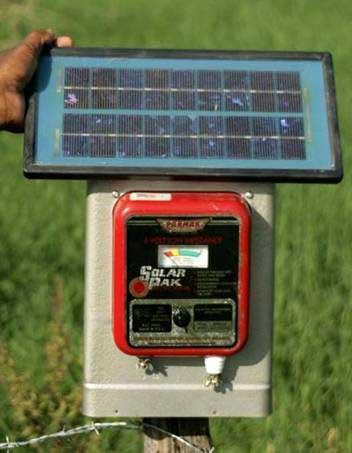
25 Calibration YOU are responsible for ensuring that you operate within the Amateur bands! Radio dials can be analog or digital. DO NOT assume that they are always correct! Older radios use Crystal Calibrators to enable you to check the accuracy of the dial. Newer, synthesized, radios use a master time base in the microprocessor to derive frequency information. If that time base is off, so will the calibration. Use WWV / WWVH to calibrate your radio.
26 Simple Crystal Radio

27 AM Demodulation Signal Diode Action Low Pass Filter

28 Baby Grand Crystal Receiver
29 Tuned Radio Receiver A Tuned Radio (TRF) receiver has several RF amplifier stages followed by detector and audio amplifier stages. Each RF amplifier stage must be tuned individually. This is a very cumbersome process! For technical reasons, it is also difficult to achieve sufficient selectivity as the frequency increases.
30 Tuned Radio Receiver Antenna BPF Amp BPF Amp BPF Amp Spkr Det

31 American Beauty TRF Receiver
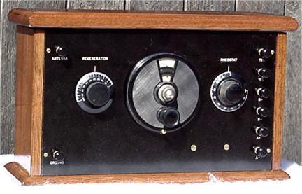
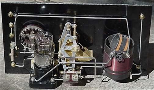
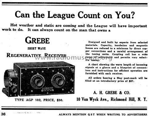
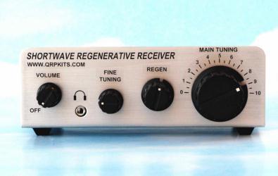
32 Regenerative Receiver High sensitivity High selectivity (for weaker signals) Poor stability Poor immunity to overload Mediocre resettability / logging Generates a signal that can cause interference to others. Cheap + easy to build! Best performance requires careful design
33 Regenerative Receiver
34
35
36 The Superheterodyne Receiver In 1918 Major Edwin Armstrong developed the Superheterodyne receiver to correct the problems of the TRF radio. It mixes an incoming signal with a locally generated RF signal to produce an Intermediate (IF). That IF is then amplified, detected and turned into sound. The Superhet is still the most popular form of receiver, accounting for 99% or more!
37 Superheterodyne Receiver Antenna Radio Amplifier Mixer Filter High Oscillator Intermediate Amplifier Speaker Or Headphone Audio Amplifier Detector
38 Superheterodyne Receiver Antenna Radio Amplifier Mixer Filter High Oscillator Intermediate Amplifier Speaker Or Headphone Audio Amplifier Detector
39 Antenna While technically the antenna picks up a wide range of frequencies, in practice some antennas are more narrow-banded. Resonant antennas eg: a half-wave dipole, are better able to pick up signals around their design frequency. Non-resonant antennas eg: Rhombics, can be used over a much broader frequency range.
40 Superheterodyne Receiver Antenna Radio Amplifier Mixer Filter High Oscillator Intermediate Amplifier Speaker Or Headphone Audio Amplifier Detector
41 Radio Amplifier The RF amplifier takes the weak signals from the antenna and amplifies them. This is usually a fairly broadband amp. In better radios it consists of a number of separate modules that cover individual bands. These modules would be selected automatically as the radio is tuned. Older radios had a manually tuned continuous preamplifier. This stage does have tuned circuits to help reject strong out-of-band signals that could cause Cross Modulation.
42 Superheterodyne Receiver Antenna Radio Amplifier Mixer Filter High Oscillator Intermediate Amplifier Speaker Or Headphone Audio Amplifier Detector
43 HF Oscillator and Mixer The HF Oscillator, more usually called the Local Oscillator, generates an RF signal that is higher or lower than the desired receive frequency by an amount called the Intermediate. It mixes with the signal from the RF Amp inside the Mixer. Output from the mixer is the sum and difference of the two signals. One of those two signals is the Intermediate. The choice is an engineering decision.
44 Superheterodyne Receiver Antenna Radio Amplifier Mixer Filter High Oscillator Intermediate Amplifier Speaker Or Headphone Audio Amplifier Detector
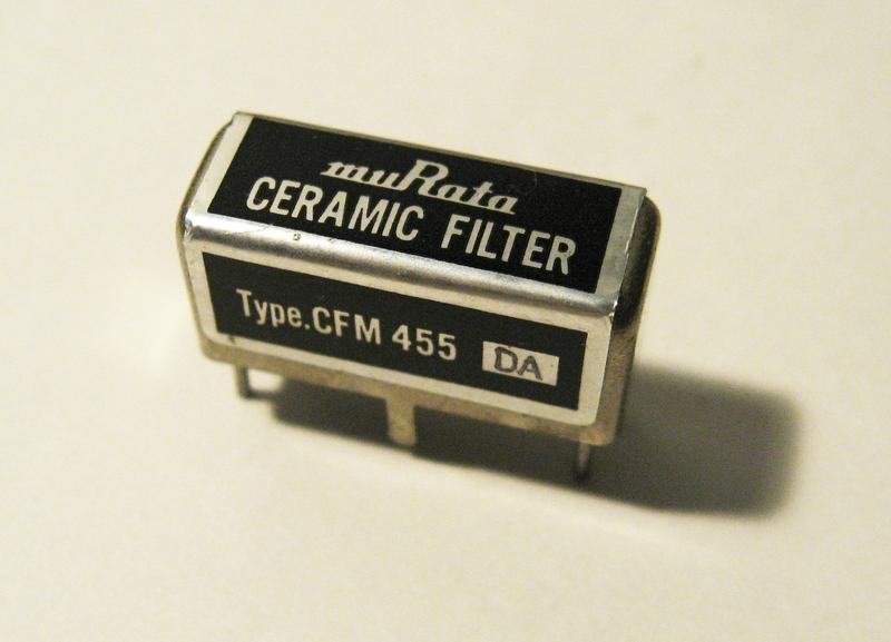
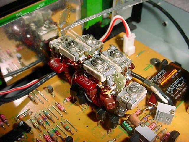
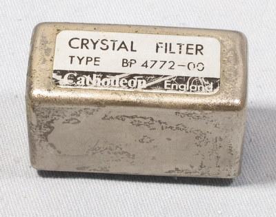
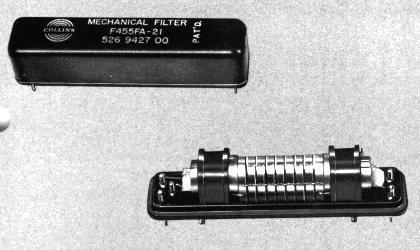
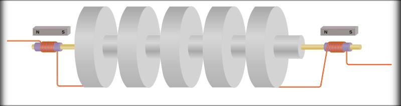
45 Filter and IF Amplifier The Filter can be mechanical, crystal or ceramic. Newer radios employ a synthetic filter using Digital Signal Processing (DSP) techniques. It filters out not just the non-if signal, but is also the primary location where selectivity is obtained. The IF Amp can consist of several stages that amplifie the IF signal. Because the IF has been predefined by the receiver s design, the IF amp does not need to be tuned after calibration by the manufacturer. A total of db gain.
46 Receiver Filters Receivers often have several filters that can be switched in as required by the mode. Examples of the filter widths and the usual mode they would be used for are: 250 Hz CW (for severe interference) 500 Hz CW (for more relaxed conditions) 2.4 khz SSB 6 khz AM, possibly SSB if band is not busy
47
48 Superheterodyne Receiver Antenna Radio Amplifier Mixer Filter High Oscillator Intermediate Amplifier Speaker Or Headphone Audio Amplifier Detector
49 Detector Stage The amplified IF signal is sent to the Detector, where it is rectified and the RF filtered out. This leaves only a weak audio signal which is sent to the AF amplifier before going to the speaker or headphones.

50 AM Demodulation IF Transformer
51 Superhet Example In order to better illustrate how a Superhet receiver works, let s look at an example of how the frequency conversion process operates. We want to receive a signal on 3.8 MHz (3800 khz) Assume our receiver has an IF of 455 khz.
52 3800 khz signal Antenna Radio Amplifier Mixer Filter High Oscillator Intermediate Amplifier Speaker Or Headphone Audio Amplifier Detector
53 3800 khz signal 3800 khz Antenna Radio Amplifier Mixer Filter 3800 khz khz = 4255 khz High Oscillator Intermediate Amplifier Speaker Or Headphone Audio Amplifier Detector
54 3800 khz signal 3800 khz = 8055 khz and = 455 khz Antenna Radio Amplifier Mixer Filter 3800 khz khz = 4255 khz High Oscillator Intermediate Amplifier Speaker Or Headphone Audio Amplifier Detector
55 3800 khz signal 3800 khz = 8055 khz and = 455 khz Antenna Radio Amplifier Mixer Filter 3800 khz khz = 4255 khz High Oscillator 455 khz Intermediate Amplifier Speaker Or Headphone Audio Amplifier Detector
56 3800 khz signal 3800 khz = 8055 khz and = 455 khz Antenna Radio Amplifier Mixer Filter 3800 khz khz = 4255 khz High Oscillator 455 khz 455 khz Intermediate Amplifier Speaker Or Headphone Audio Amplifier Detector
57 3800 khz signal 3800 khz = 8055 khz and = 455 khz Antenna Radio Amplifier Mixer Filter 3800 khz khz = 4255 khz High Oscillator 455 khz 455 khz Intermediate Amplifier AF Speaker Or Headphone AF Audio Amplifier AF Detector
58 Advantages of the Superhet Much more sensitive, selective and stable than TRF radios. By converting higher frequencies to the IF, we are able to design much more selective and sensitive filters and amplifiers that use more reliable components. Much easier to use.
59 Primary Disadvantage Superhets have one big problem however they are subject to receiving images, or stations that are not actually on the frequency we are listening to. This occurs when a station is transmitting on a frequency twice the IF away from the desired frequency.
60
61 No Image 3800 khz = 8055 khz and = 455 khz Radio Amplifier 3800 khz 4255 khz 3800 khz khz = 4255 khz Mixer High Oscillator 455 khz Filter
62 Image 3800 khz (2 x 455) = 4710 khz = 8055 khz and = 455 khz = 455 khz Radio Amplifier 3800 khz 4710 khz 4255 khz 3800 khz khz = 4255 khz Mixer High Oscillator 455 khz Filter
63 The Solution! More expensive superhets employ double or triple conversion to improve image rejection. The first IF is chosen so that it is larger than the bandwidth of the bandpass filters in the front end of the receiver, and so the image not make it to mixer stage. The first IF signal is then amplified, and converted again to a lower IF to take advantage of the greater selectivity available at lower Intermediate Frequencies.
64 Advantages of a High First IF Front End RF Amplifier s Response Local Oscillator signal (low IF) Desired Signal Image Signal 2 x IF (low)
65 Advantages of a High First IF Front End RF Amplifier s Response Desired Signal Local Oscillator signal (low IF) Local Oscillator signal (high IF) Image Signal Image Signal 2 x IF (low) 2 x IF (high)
66 Single versus Dual Conversion Superhet Receiver
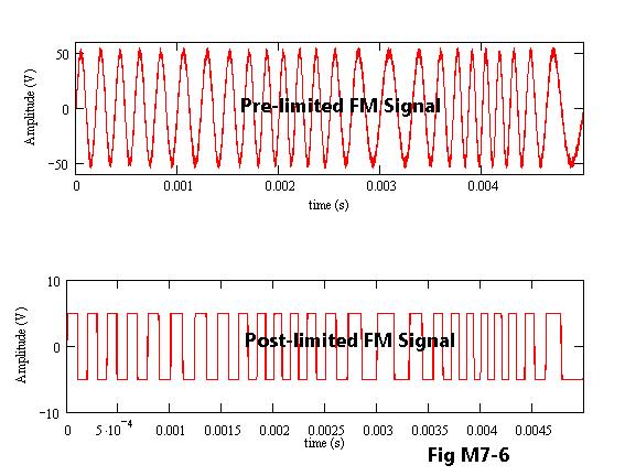
67 FM Receiver The FM receiver is very similar to an AM receiver up to the IF Amplifier. Instead of a Detector however, the FM receiver uses two different stages: Limiter Discriminator
68 FM Receiver Antenna Radio Amplifier Mixer Filter High Oscillator Intermediate Amplifier Speaker Or Headphone Audio Amplifier Discriminator Limiter
69 Limiter The Limiter Stages are high gain amplifiers that remove all traces of Amplitude Modulation from the received signal. Static crashes are mostly amplitude modulated, and so are removed by the Limiter. This gives FM its greatest benefit a very high SNR Signal to Noise Ratio.
70
71 Discriminator The Discriminator converts frequency variations into voltage variations. This is fed to the Audio Amplifier and then the speaker or headphones.
72 Discriminator Common types include : Foster-Seeley Detector Ratio Detector Quadrature Detector Slope detector Phase-locked Loop Foster-Seeley Detector
73 Receiving SSB and CW The SSB/CW receiver is very similar to an AM receiver up to the IF Amplifier. Instead of a Detector however, the SSB/CW receiver uses two different stages: Product Detector Beat Oscillator (BFO).
74 Carrier is suppressed Amplitude Modulation Double Sideband Suppressed Carrier
75 Lower Sideband Upper Sideband Single Sideband Suppressed Carrier
76 SSB / CW Superheterodyne Receiver Antenna Radio Amplifier Mixer Filter High Oscillator Intermediate Amplifier Speaker Or Headphone Audio Amplifier Product Detector Beat Freq Oscillator
77 Product Detector Because the carrier has been removed from an SSB transmission, it must be re-inserted so that the original audio can be recovered. This is accomplished using the Product Detector. The source of the carrier is the Beat Oscillator (BFO).
78 Beat Oscillator (BFO) The BFO is an oscillator that replaces the carrier in an SSB transmission. CW transmissions also require a carrier to beat against (mix with) to produce an audio tone. Older receivers use a BFO that could be varied in frequency as the operating mode is changed from USB to LSB to CW. Modern radios automatically switch the operating frequency of the BFO as the mode is changed.
79 Product Detector
80 Beat Oscillator
81 Audio Filters Hams sometimes employed active or passive external audio filters with older receivers in an effort to remove interference and improve selectivity. A Notch Filter can be used to remove an interfering carrier signal (ie: CW signal). To improve CW selectivity, an audio bandpass filter for Hz would be appropriate. Modern radios incorporate DSP techniques even more effectively, at the IF stages rather than the audio stages.

82 MFJ- 784B DSP Filter
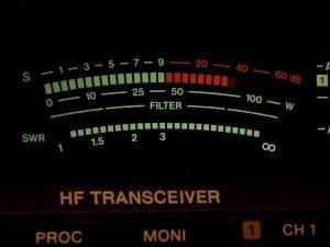
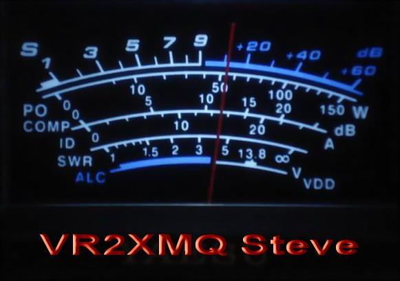
83 Signal Strength Meters An S-Meter enables you to make comparisons between received signals. Unfortunately, even on identical receivers, most S- meters are not properly calibrated and will give different readings when using the same antenna. The scale is divided into 9 increments, designated S0 to S9, up to the center point of the meter. The scale is then graduated in db, usually in multiples of 10. A signal strength report would be S6 or S9 plus 15 db.
84 S-Meter Standards According to the standards adopted by the International Amateur Radio Union (IARU) in 1981, S9 corresponds to a signal strength of 50 microvolts at the receiver s 50 ohm impedance antenna input. Each S unit then reflects a 6dB change in signal strength. This is rarely achieved, as S-meters are often not linear in their response. Still, they give a relative indication of signal strengths!
85 S-Meter

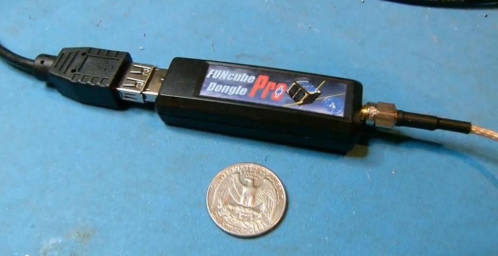
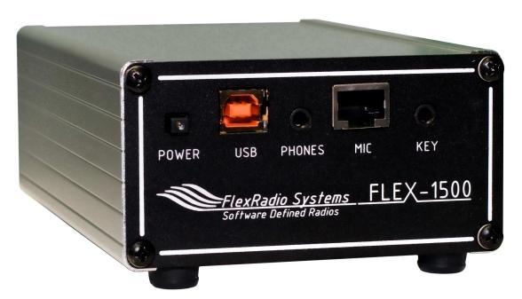
86 Software Defined Radios
87
88 Questions?

89 Two Section Tuning Capacitor
90
Radio Receivers. Al Penney VO1NO
 Radio Receivers Al Penney VO1NO Role of the Receiver The Antenna must capture the radio wave. The desired frequency must be selected from all the EM waves captured by the antenna. The selected signal is
Module 8 Theory. dbs AM Detector Ring Modulator Receiver Chain. Functional Blocks Parameters. IRTS Region 4
 Module 8 Theory dbs AM Detector Ring Modulator Receiver Chain Functional Blocks Parameters Decibel (db) The term db or decibel is a relative unit of measurement used frequently in electronic communications
Technician License Course Chapter 3 Types of Radios and Radio Circuits. Module 7
 Technician License Course Chapter 3 Types of Radios and Radio Circuits Module 7 Radio Block Diagrams Radio Circuits can be shown as functional blocks connected together. Knowing the description of common
HF Receivers, Part 2
 HF Receivers, Part 2 Superhet building blocks: AM, SSB/CW, FM receivers Adam Farson VA7OJ View an excellent tutorial on receivers NSARC HF Operators HF Receivers 2 1 The RF Amplifier (Preamp)! Typical
RADIO RECEIVERS ECE 3103 WIRELESS COMMUNICATION SYSTEMS
 RADIO RECEIVERS ECE 3103 WIRELESS COMMUNICATION SYSTEMS FUNCTIONS OF A RADIO RECEIVER The main functions of a radio receiver are: 1. To intercept the RF signal by using the receiver antenna 2. Select the
ADJUSTING YOUR HF RECEIVER
 ADJUSTING YOUR HF RECEIVER N5KIP January 31, 2017 Disclaimers What works on one model of radio might not work well on another CW (narrow bandwidth) and SSB (wider bandwidth) will require different receiver
Receiver Design. Prof. Tzong-Lin Wu EMC Laboratory Department of Electrical Engineering National Taiwan University 2011/2/21
 Receiver Design Prof. Tzong-Lin Wu EMC Laboratory Department of Electrical Engineering National Taiwan University 2011/2/21 MW & RF Design / Prof. T. -L. Wu 1 The receiver mush be very sensitive to -110dBm
Introduction to Receivers
 Introduction to Receivers Purpose: translate RF signals to baseband Shift frequency Amplify Filter Demodulate Why is this a challenge? Interference Large dynamic range required Many receivers must be capable
RF/IF Terminology and Specs
 RF/IF Terminology and Specs Contributors: Brad Brannon John Greichen Leo McHugh Eamon Nash Eberhard Brunner 1 Terminology LNA - Low-Noise Amplifier. A specialized amplifier to boost the very small received
Interference & Suppression Page 59
 INTERFERENCE Interference & Suppression Page 59 Front-End Overload, Cross-Modulation What is meant by receiver overload? Interference caused by strong signals from a nearby transmitter What is one way
The New England Radio Discussion Society electronics course (Phase 4, cont d) Introduction to receivers
 Introduction to receivers") The New England Radio Discussion Society electronics course (Phase 4, cont d) Introduction to receivers AI2Q April 2017 REVIEW: a VFO, phase-locked loop (PLL), or direct digital synthesizer (DDS), can
The New England Radio Discussion Society electronics course (Phase 4, cont d) Introduction to receivers AI2Q April 2017 REVIEW: a VFO, phase-locked loop (PLL), or direct digital synthesizer (DDS), can
Topic Advanced Radio Receivers. Explain that an RF amplifier can be used to improve sensitivity;
 Learning Objectives: At the end of this topic you will be able to; Explain that an RF amplifier can be used to improve sensitivity; Explain that a superheterodyne receiver offers improved selectivity and
ANALOG COMMUNICATION
 ANALOG COMMUNICATION TRAINING LAB Analog Communication Training Lab consists of six kits, one each for Modulation (ACL-01), Demodulation (ACL-02), Modulation (ACL-03), Demodulation (ACL-04), Noise power
KWM-2/2A Transceiver THE COLLINS KWM-2/2A TRANSCEIVER
 KWM-2/2A Transceiver Click the photo to see a larger photo Click "Back" button on browser to return Courtesy of Norm - WA3KEY THE COLLINS KWM-2/2A TRANSCEIVER Unmatched for versatility, dependability and
Icom IC-9100 HF/VHF/UHF transceiver
 263 Walsall Road, Great Wyrley, Walsall, WS6 6DL Established 1997. Open Monday - Friday 9am - 5pm and Saturday 9.30am - 4pm Tel: 01922 414 796 Fax: 01922 417829 Skype: radioworld_uk Icom IC-9100 HF/VHF/UHF
RFID Systems: Radio Architecture
 RFID Systems: Radio Architecture 1 A discussion of radio architecture and RFID. What are the critical pieces? Familiarity with how radio and especially RFID radios are designed will allow you to make correct
General Class License Theory II. Dick Grote K6PBF
 General Class License Theory II Dick Grote K6PBF k6pbfdick@gmail.com 1 Introduction In the first theory class we talked about basic electrical principles and components. Now we will build on this to learn
Technician License Course Chapter 3. Lesson Plan Module 7 Types of Radio Circuits
 Technician License Course Chapter 3 Lesson Plan Module 7 Types of Radio Circuits The Basic Transceiver Combination of transmitter and receiver Abbreviated XCVR (X = trans) Antenna switched between transmitter
OBJECTIVES EQUIPMENT LIST
 1 Reception of Amplitude Modulated Signals AM Demodulation OBJECTIVES The purpose of this experiment is to show how the amplitude-modulated signals are demodulated to obtain the original signal. Also,
PRACTICE. Amateur Radio Operator Certificate Examination. Advanced Qualification
 Innovation, Science and Economic Development Canada Innovation, Sciences et Développement économique Canada Amateur Radio Operator Certificate Examination Advanced Qualification 2018-06-30 To pass this
Amateur Radio Examination EXAMINATION PAPER No. 260 MARKER S COPY
 01-7-(a) An authorised officer from the Ministry of Business, Innovation & Employment can inspect a General Amateur Operator's Certificate of Competency: a at any time b during business hours c at any
THE AMAZING BARLOW WADLEY XCR-30 CRYSTAL CONTROLLED 30 BAND TRANSISTOR RADIO. (A method to set the AGC) H. Holden, 2018.
 H. Holden, 2018.") THE AMAZING BARLOW WADLEY XCR-30 CRYSTAL CONTROLLED 30 BAND TRANSISTOR RADIO. (A method to set the AGC) H. Holden, 2018. Introduction: The Barlow Wadley XCR-30 radio is well known to amateur radio enthusiasts
THE AMAZING BARLOW WADLEY XCR-30 CRYSTAL CONTROLLED 30 BAND TRANSISTOR RADIO. (A method to set the AGC) H. Holden, 2018. Introduction: The Barlow Wadley XCR-30 radio is well known to amateur radio enthusiasts
CHAPTER 13 TRANSMITTERS AND RECEIVERS
 CHAPTER 13 TRANSMITTERS AND RECEIVERS Frequency Modulation (FM) Receiver Frequency Modulation (FM) Receiver FREQUENCY MODULATION (FM) RECEIVER Superheterodyne Receiver Heterodyning The word heterodyne
Technician License Course Chapter 2. Lesson Plan Module 3 Modulation and Bandwidth
 Technician License Course Chapter 2 Lesson Plan Module 3 Modulation and Bandwidth The Basic Radio Station What Happens During Radio Communication? Transmitting (sending a signal): Information (voice, data,
HF Receivers, Part 3
 HF Receivers, Part 3 Introduction to frequency synthesis; ancillary receiver functions Adam Farson VA7OJ View an excellent tutorial on receivers Another link to receiver principles NSARC HF Operators HF
 HF Receiver Testing: Issues & Advances (also presented at APDXC 2014, Osaka, Japan, November 2014) Adam Farson VA7OJ Copyright 2014 North Shore Amateur Radio Club NSARC HF Operators HF RX Testing 1 HF
4/30/2012. General Class Element 3 Course Presentation. Practical Circuits. Practical Circuits. Subelement G7. 2 Exam Questions, 2 Groups
 General Class Element 3 Course Presentation ti ELEMENT 3 SUB ELEMENTS General Licensing Class Subelement G7 2 Exam Questions, 2 Groups G1 Commission s Rules G2 Operating Procedures G3 Radio Wave Propagation
High Dynamic Range Receiver Parameters
 High Dynamic Range Receiver Parameters The concept of a high-dynamic-range receiver implies more than an ability to detect, with low distortion, desired signals differing, in amplitude by as much as 90
Ham Radio Training. Level 1 Technician Level. Presented by Richard Bosch KJ4WBB
 Ham Radio Training Level 1 Technician Level Presented by Richard Bosch KJ4WBB In this chapter, you ll learn about: What is a radio signal The characteristics of radio signals How modulation adds information
Chapter 5 AM Receivers
 Chapter 5 AM Receivers Prepared by Prof.V.K.Jain 1 Lecture outcome After studying this lecture, you should be able to: Describe the basic superheterodyne system Choose suitable intermediate frequencies
Amateur Wireless Station Operators License Exam
 Amateur Wireless Station Operators License Exam Study material 2017 South India Amateur Radio Society, Chennai CHAPTER 4 1 Chapter 4 Amateur Wireless Station Operators License Exam Study Material Chapter
Operating Station Equipment
 Amateur Radio License Class Operating Station Equipment Presented by Steve Gallafent October 3, 2007 Operating Station Equipment Modulation Modulation is the process of adding information to a radio signal
Modulation Methods Frequency Modulation
 Modulation Methods Frequency Modulation William Sheets K2MQJ Rudolf F. Graf KA2CWL The use of frequency modulation (called FM) is another method of adding intelligence to a carrier signal. While simple
Transmitters and receivers
 Chapter 3 Transmitters and receivers Transmitters and receivers are used extensively in aircraft communication and navigation systems. In conjunction with one ore more antennas, they are responsible for
Amateur Radio Examination EXAMINATION PAPER No. 275 MARKER S COPY
 01-6-(d) An Amateur Station is quoted in the regulations as a station: a for training new radio operators b using amateur equipment for commercial purposes c for public emergency purposes d in the Amateur
: Triple PLL, lowest reference frequency 10 khz. : ± 5 khz in 10 Hz steps, synthesized.
 PETER DE CONINCK HAGENUK RX 1001MVB RECEIVER ONL4234 SERIAL N 5820-310-6162 BELGIAN SWL DRAWING N 97 8 2.164 Technical data Frequency range Frequency resolution Frequency tuning Frequency synthesizer Frequency
Lesson 9: Base Stations
 Lesson 9: Base Stations Preparation for Amateur Radio Technician Class Exam Topics Home Stations Basic Station Layout RTTY and Data Communications Station Accessories Wavelengths Feed Lines Impedance-matching
Introduction Introduction to radio frequencies p. 3 What are the 'radio frequencies'? p. 3 Why are radio frequencies different? p.
 Foreword p. xi Preface p. xiii Introduction Introduction to radio frequencies p. 3 What are the 'radio frequencies'? p. 3 Why are radio frequencies different? p. 3 What this book covers p. 3 Signals and
MAHALAKSHMI ENGINEERING COLLEGE-TRICHY QUESTION BANK UNIT IV PART-A
 MAHALAKSHMI ENGINEERING COLLEGE-TRICHY QUESTION BANK SATELLITE COMMUNICATION DEPT./SEM.:ECE/VIII UNIT IV PART-A 1. What are the advantages of the super heterodyne receiver over TRF receiver? (AUC MAY 2004)
IC-R8500 Test Report. By Adam Farson VA7OJ/AB4OJ
 IC-R8500 Test Report By Adam Farson VA7OJ/AB4OJ Iss. 1, Dec. 14, 2015. Figure 1: The Icom IC-R8500. Introduction: This report presents results of an RF lab test suite performed on the IC- R8500 receiver.
Norfolk Amateur Radio Club
 Norfolk Amateur Radio Club The Transmitter & Transmitter Interference Nick M0HGU & Steve G3PND Plan for the Day The Transmitter Introduction, Block diagrams Oscillators, Buffers & Multipliers Modulation
Technician Licensing Class. Lesson 4. presented by the Arlington Radio Public Service Club Arlington County, Virginia
 Technician Licensing Class Lesson 4 presented by the Arlington Radio Public Service Club Arlington County, Virginia 1 Quiz Sub elements T6 & T7 2 Good Engineering Practice Sub element T8 3 A Basic Station
Amplitude Modulated Systems
 Amplitude Modulated Systems Communication is process of establishing connection between two points for information exchange. Channel refers to medium through which message travels e.g. wires, links, or
GRAND STRAND AMATEUR RADIO CLUB
 The GRAND STRAND AMATEUR RADIO CLUB (GSARC) Myrtle Beach SC is offering used amateur related equipment for sale. Written bids may be submitted to the GSARC up to Friday, November 23 rd, 2018. Only currently
Receiver Specification?
 Receiver Specification? What do they mean? Steve Finch AIØW What We re Doing Today Stage-by-stage receiver gain what do they mean? Specifications of interest why? Test equipment needed Learn about the
B.Tech II Year II Semester (R13) Supplementary Examinations May/June 2017 ANALOG COMMUNICATION SYSTEMS (Electronics and Communication Engineering)
 Supplementary Examinations May/June 2017 ANALOG COMMUNICATION SYSTEMS (Electronics and Communication Engineering)") Code: 13A04404 R13 B.Tech II Year II Semester (R13) Supplementary Examinations May/June 2017 ANALOG COMMUNICATION SYSTEMS (Electronics and Communication Engineering) Time: 3 hours Max. Marks: 70 PART A
Code: 13A04404 R13 B.Tech II Year II Semester (R13) Supplementary Examinations May/June 2017 ANALOG COMMUNICATION SYSTEMS (Electronics and Communication Engineering) Time: 3 hours Max. Marks: 70 PART A
Technician License Course Chapter 2. Lesson Plan Module 2 Radio Signals and Waves
 Technician License Course Chapter 2 Lesson Plan Module 2 Radio Signals and Waves The Basic Radio Station What Happens During Radio Communication? Transmitting (sending a signal): Information (voice, data,
Amateur Radio Examination EXAMINATION PAPER No. 276 MARKER S COPY
 01-3-(a) The Amateur Service in New Zealand is administered through this prime document: a the New Zealand Radiocommunications Regulations b the Broadcasting Act c the Telecommunications Act d the Radio
4/29/2012. General Class Element 3 Course Presentation. Signals and Emissions. SignalSignals and Emissionsissions. Subelement G8
 General Class Element 3 Course Presentation ti ELEMENT 3 SUB ELEMENTS General Licensing Class Subelement G8 Signals and Emissions 2 Exam Questions, 2 Groups G1 Commission s Rules G2 Operating Procedures
RADIO AMATEUR EXAM GENERAL CLASS
 RAE-Lessons by 4S7VJ 1 CHAPTER-5 RADIO AMATEUR EXAM GENERAL CLASS By 4S7VJ 5.1 RECEIVER The main purpose of a radio receiver is receive RF signal and convert to AF signal or get the audio signal out from
Amateur Wireless Station Operators License Exam
 Amateur Wireless Station Operators License Exam Study material 2017 South India Amateur Radio Society, Chennai CHAPTER 5 1 Chapter 5 Amateur Wireless Station Operators License Exam Study Material Chapter
Test Equipment. PHYS 401 Physics of Ham Radio
 Test Equipment Voltmeter - an instrument that is used to measure voltage. It is used in parallel with a circuit to be measured. a series resistor extends the range of the meter. Ammeter - an instrument
Code No: R Set No. 1
 Code No: R05220405 Set No. 1 II B.Tech II Semester Regular Examinations, Apr/May 2007 ANALOG COMMUNICATIONS ( Common to Electronics & Communication Engineering and Electronics & Telematics) Time: 3 hours
UNIT-2 Angle Modulation System
 UNIT-2 Angle Modulation System Introduction There are three parameters of a carrier that may carry information: Amplitude Frequency Phase Frequency Modulation Power in an FM signal does not vary with modulation
MFJ-722 INSTRUCTIONS
 MFJ-722 INSTRUCTIONS INTRODUCTION I The MFJ-722 OPTIMIZER consists of a tunable notch filter combined with a switch selectable highpass/lowpass filter (SSB) and bandpass (CW) filter. This filtering capability
Technical Data. Compact Digital HF Receiver WJ-8710A WATKINS-JOHNSON. Features
 May 1996 Technical Data WATKINS-JOHNSON Compact Digital HF Receiver WJ-8710A The WJ-8710A is a fully synthesized, general-purpose HF receiver for surveillance and monitoring of RF communications from 5
Modulation is the process of impressing a low-frequency information signal (baseband signal) onto a higher frequency carrier signal
 onto a higher frequency carrier signal") Modulation is the process of impressing a low-frequency information signal (baseband signal) onto a higher frequency carrier signal Modulation is a process of mixing a signal with a sinusoid to produce
Modulation is the process of impressing a low-frequency information signal (baseband signal) onto a higher frequency carrier signal Modulation is a process of mixing a signal with a sinusoid to produce
Problems from the 3 rd edition
 (2.1-1) Find the energies of the signals: a) sin t, 0 t π b) sin t, 0 t π c) 2 sin t, 0 t π d) sin (t-2π), 2π t 4π Problems from the 3 rd edition Comment on the effect on energy of sign change, time shifting
Receiver Architecture
 Receiver Architecture Receiver basics Channel selection why not at RF? BPF first or LNA first? Direct digitization of RF signal Receiver architectures Sub-sampling receiver noise problem Heterodyne receiver
Definitions of Technical Terms
 Definitions of Technical Terms Terms Ammeter Amperes, Amps Band Capacitor Carrier Squelch Diode Dipole Definitions How is an ammeter usually connected = In series with the circuit What instrument is used
Transceiver selection and Specs.
 Transceiver selection and Specs. Transceivers 1956-2018 From TUBES to SDR Covers 20-10 meters in 100Khz segments, 10 available, crystal needed for each. Plug in crystal holder. 100 Watts output, final
TDA7000 for narrowband FM reception
 TDA7 for narrowband FM reception Author: Author: W.V. Dooremolen INTRODUCTION Today s cordless telephone sets make use of duplex communication with carrier frequencies of about.7mhz and 49MHz. In the base
Digital HF Receiver WJ-8723
 Developmental Specification WATKINS-JOHNSON April 1996 Digital HF Receiver WJ-8723 Description The WJ-8723 is a fully synthesized, general-purpose HF receiver that monitors RF communications from 5 khz
The G4EGQ RAE COURSE Lesson 9 Transmitters Lesson 8 looked at a simple transmitter exciter comprising of oscillator, buffer and multiplier stages.
 Lesson 8 looked at a simple transmitter exciter comprising of oscillator, buffer and multiplier stages. The power amplifier The output from the exciter is usually very low and it is necessary to amplify
Television and video engineering
 Television and video engineering Unit-4 Television Receiver systems Objectives: To learn the requirements of TV receiver Study of monochrome and Colour TV receivers. To learn functions of Tuning circuits
The 21st Century R-390A/URR Reference Y2K-R3 Edited 7/09: No Technical Changes Chapter 2 - Operation. Page Table Of Contents 2-1
 Edited 7/09: No Technical Changes Chapter 2 - Operation Page Table Of Contents 2-1 2.1 Introduction. 2-2 2.2 Controls and Indicators 2-2 2.3 Operating Instructions And Control Settings 2-9 2.3.1 Pre-operational
Wideband Receiver for Communications Receiver or Spectrum Analysis Usage: A Comparison of Superheterodyne to Quadrature Down Conversion
 A Comparison of Superheterodyne to Quadrature Down Conversion Tony Manicone, Vanteon Corporation There are many different system architectures which can be used in the design of High Frequency wideband
LnR Precision, Inc. 107 East Central Avenue, Asheboro, NC
 LD5 CW/SSB QRP Transceiver Quick guide manual Description: At the development base of the digital signal processing unit, an algorithm is embedded for IQ processing of the channels with phase suppression
Wideband Receiver Design
 Wideband Receiver Design Challenges and Trade-offs of a Wideband Tuning Range in Wireless Microphone Receivers in the UHF Television Band About this White Paper Professional wireless microphone systems
EE470 Electronic Communication Theory Exam II
 EE470 Electronic Communication Theory Exam II Open text, closed notes. For partial credit, you must show all formulas in symbolic form and you must work neatly!!! Date: November 6, 2013 Name: 1. [16%]
An Arduino DCR-SDR Project: Part 1
 First published in the May-Jun 2015 issue of The Canadian Amateur An Arduino DCR-SDR Project: Part 1 INTRODUCTION In this part, we ll build a simple direct conversion receiver (DCR) software defined radio
Elmer Session Hand Out for 3/3/11 de W6WTI. Some Common Controls Found On Amateur Radio Transceivers. (From ARRL web site tutorial)
") Elmer Session Hand Out for 3/3/11 de W6WTI Some Common Controls Found On Amateur Radio Transceivers. (From ARRL web site tutorial) The placement of the controls may vary from manufacturer to manufacturer
Elmer Session Hand Out for 3/3/11 de W6WTI Some Common Controls Found On Amateur Radio Transceivers. (From ARRL web site tutorial) The placement of the controls may vary from manufacturer to manufacturer
Chapter 3. Question Mar No
 Chapter 3 Sr Question Mar No k. 1 Write any two drawbacks of TRF radio receiver 1. Instability due to oscillatory nature of RF amplifier.. Variation in bandwidth over tuning range. 3. Insufficient selectivity
On The Causes And Cures Of Audio Distortion Of Received AM Signals Due To Fading
 On The Causes And Cures Of Audio Distortion Of Received AM Signals Due To Fading Dallas Lankford, 2/6/06, rev. 9/25/08 The purpose of this article is to investigate some of the causes and cures of audio
MFJ-752C SIGNAL ENHANCER II
 MFJ-752C SIGNAL ENHANCER II INTRODUCTION The improved MFJ-752C SIGNAL ENHANCER II is comprised of two tunable audio filtering systems designed to clarity and remove interfering signals from both voice
Chapter 3. Electricity, Components and Circuits. Metric Units
 Chapter 3 Electricity, Components and Circuits Metric Units 1 T5B02 -- What is another way to specify a radio signal frequency of 1,500,000 hertz? A. 1500 khz B. 1500 MHz C. 15 GHz D. 150 khz T5B07 --
Receiver Performance Transmitted BW Contest Fatigue Rob Sherwood NCØ B
 Receiver Performance Transmitted BW Contest Fatigue Rob Sherwood NCØ B Limitations to a better contest score may not always be obvious. Sherwood Engineering What is important in a contest environment?
The amazing evolution of the 706 series
 The amazing evolution of the 706 series The IC-706MKIIG carries on the 706 series tradition of base station performance and features in a mobile reg-sized package. Building on this legacy, frequency coverage
Technical Data. Digital HF Receiver WJ-8712A WATKINS-JOHNSON. Features
 May 1996 Technical Data WATKINS-JOHNSON Digital HF Receiver WJ-8712A The WJ-8712A is a fully synthesized, general-purpose HF receiver for surveillance and monitoring of RF communications from 5 khz to
note application Measurement of Frequency Stability and Phase Noise by David Owen
 application Measurement of Frequency Stability and Phase Noise note by David Owen The stability of an RF source is often a critical parameter for many applications. Performance varies considerably with
hallicrafters PERFORMANCE SPECIFICATIONS MODEL: SR-2000 LATEST REVISION: 18 JAN 66 Code ident # Specification #
 hallicrafters PERFORMANCE SPECIFICATIONS MODEL: SR-2000 LATEST REVISION: 18 JAN 66 Code ident # 26916 Specification # 093-002154 I. GENERAL A. Power input 117V 50-60 cycles from a source capable of delivering
TS-480 Replacing the standard MCF (monolithic crystal filter)
") TS-480 Replacing the standard MCF (monolithic crystal filter) The TS-480 has a monolithic crystal filter installed in the second IF (10,695 MHz). This is a 2,4 khz filter which is used on both RX and TX
TS-480 Replacing the standard MCF (monolithic crystal filter) The TS-480 has a monolithic crystal filter installed in the second IF (10,695 MHz). This is a 2,4 khz filter which is used on both RX and TX
Preliminary features of the SDR-X receiver SDR-X , PowerSDR Winrad Winrad DDS SFDR SFDR AD995 AD99 1
 Preliminary features of the SDR-X receiver The SDR-X receiver, in its full version is capable of continuously tuning the entire HF spectrum, 6m ( 50-52 MHz) band included. SSB, AM etc. demodulation, bandpass
AM, PM and FM mo m dula l ti t o i n
 AM, PM and FM modulation What is amplitude modulation In order that a radio signal can carry audio or other information for broadcasting or for two way radio communication, it must be modulated or changed
Second Hand Yaesu FTDX5000MP HF base station transceiver
 263 Walsall Road, Great Wyrley, Walsall, WS6 6DL Established 1997. Open Monday - Friday 9am - 5pm and Saturday 9.30am - 4pm Tel: 01922 414 796 Fax: 01922 417829 Skype: radioworld_uk Second Hand Yaesu FTDX5000MP
VHF/UHF Wideband ViXIceptor WJ-8621
 Developmental Specification WATKINS-JOHNSON May 1997 VHF/UHF Wideband ViXIceptor WJ-8621 The WJ-8621 is a general-purpose VHF/UHF receiver covering a 20 to 2700 MHz frequency range. WJ packages the unit
COMM 704: Communication Systems
 COMM 704: Communication Lecture 1: Introduction Dr. Mohamed Abd El Ghany, Mohamed.abdel-ghany@guc.edu.eg Course Objective Give an introduction to the basic concepts of electronic communication systems
Technician License Course Chapter 5. Lesson Plan Module 11 Transmitters, Receivers and Transceivers
 Technician License Course Chapter 5 Lesson Plan Module 11 Transmitters, Receivers and Transceivers Generalized Transceiver Categories Mobile Single Band Dual Band All Band Multimode Handheld (HT) VHF/UHF
FT-897 Alignment. Local Oscillator Adjustment. PLL Adjustment
 FT-897 Local Oscillator Adjustment Reference Frequency Adjustment a. Connect a frequency counter to TP1032. b. Adjust the trimmer capacitor (TC5001) for 67.875000MHz ±5Hz on the frequency counter. c. Connect
Charan Langton, Editor
 Charan Langton, Editor SIGNAL PROCESSING & SIMULATION NEWSLETTER Baseband, Passband Signals and Amplitude Modulation The most salient feature of information signals is that they are generally low frequency.
Receiver Performance Transmitted BW Contest Fatigue Rob Sherwood NCØ B
 Receiver Performance Transmitted BW Contest Fatigue Rob Sherwood NCØ B Limitations to a better contest score may not always be obvious. Sherwood Engineering What is important in a contest environment?
Software Defined Radio! Primer + Project! Gordie Neff, N9FF! Columbia Amateur Radio Club! March 2016!
 Software Defined Radio! Primer + Project! Gordie Neff, N9FF! Columbia Amateur Radio Club! March 2016! Overview! What is SDR?! Why should I care?! SDR Concepts! Potential SDR project! 2! Approach:! This
FREQUENCY AGILE FM MODULATOR INSTRUCTION BOOK IB
 FMT615C FREQUENCY AGILE FM MODULATOR INSTRUCTION BOOK IB1215-02 TABLE OF CONTENTS SECTION SUBJECT 1.0 Introduction 2.0 Installation & Operating Instructions 3.0 Specification 4.0 Functional Description
Lecture 6. Angle Modulation and Demodulation
 Lecture 6 and Demodulation Agenda Introduction to and Demodulation Frequency and Phase Modulation Angle Demodulation FM Applications Introduction The other two parameters (frequency and phase) of the carrier
TS-590SG HF/ 50MHz All-Mode TRANSCEIVER_
 New Product Release Information Oct 2014 TS-590SG HF/ 50MHz All-Mode TRANSCEIVER_ Kenwood introduces Updated to new G version new HF/50MHz All-Mode Transceiver Four years ago we launched our best-selling
Amateur Radio Examination EXAMINATION PAPER No. 272 CANDIDATE S COPY
 01-9 The holder of a General Amateur Operator Certificate of Competency may: a retransmit public broadcasts b transmit in bands allocated to the Amateur Service c repair radio equipment for profit d transmit
Description of the AM Superheterodyne Radio Receiver
 Superheterodyne AM Radio Receiver Since the inception of the AM radio, it spread widely due to its ease of use and more importantly, it low cost. The low cost of most AM radios sold in the market is due
SUBELEMENT T4. Amateur radio practices and station set up. 2 Exam Questions - 2 Groups
 SUBELEMENT T4 Amateur radio practices and station set up 2 Exam Questions - 2 Groups 1 T4A Station setup: connecting microphones; reducing unwanted emissions; power source; connecting a computer; RF grounding;
by Cliff Pulis, KE0CP SDR Presentation - Cliff Pulis, KE0CP 1
 by Cliff Pulis, KE0CP SDR Presentation - Cliff Pulis, KE0CP 1 Basic Receiver Principles Mixing Frequencies Hetrodyn ing The IF Amplifier SDR Principles & Quadrature Phase (IQ) VHF / UHF DVB-T Dongle SDR
Exercise 1: RF Stage, Mixer, and IF Filter
 SSB Reception Analog Communications Exercise 1: RF Stage, Mixer, and IF Filter EXERCISE OBJECTIVE DISCUSSION On the circuit board, you will set up the SSB transmitter to transmit a 1000 khz SSB signal