Developing a 1296 MHz Beacon. By Kevin Murphy ZL1UJG April 2009
|
|
|
- Maximillian Lane
- 6 years ago
- Views:
Transcription
1 Developing a 1296 MHz Beacon By Kevin Murphy ZL1UJG April
2 Stage Functions Oscillator Module Multiplier Module Amplifier Module Keyer PSU Module Circulator/Filter 2
3 A good start for an oscillator module is something that is available as a kit, or already built. There is little point in going to the time and expense of creating a PCB, and purchasing components, unless you are doing original development work for a special unit. A circuit in common use is the 2 transistor Butler Oscillator. This has been around since the valve days, and has been seen in RSGB Balloon Board, G4DDK oscillator series * and the Minikits EME65 variants **, as well as in some commercial designs. * ** There are better oscillators, such as the Driscoll VHF oscillator and variants of the design such as the DISTAW, by Chris Bartram GW4DGU. 3
4 I will go into detail about the oscillator module, because of its importance in the overall unit. The EME65B kit from Minikits in Australia was selected, due to its value for money. The oscillator circuit in the EME65 (B) appeared around 1981 in RSGB publications in the Microwave source of that era ( museum.org/exhibits/mwm0018.htm). The RSGB oscillator circuit was liberated from a Plessey AMETS design used in balloons. The RSGB board was nicknamed the Balloon board The original use was with fairly wide FSK (frequency shift keying), and the component values are associated with that. The circuit hasn t really changed in the last 28 years (!) 4

5 This is the standard EME65B unit as received from Minikits. There were minor changes from the first EME65 version, with additional regulator filtering and a shielded coil for tuning the crystal oscillator. The oscillator circuit consists of the Butler 2 transistor crystal oscillator. The second transistor collector is tuned to the 3 rd Harmonic and the next transistor is used a further x2 multiplier. Output from the PCB is ~ + 10 dbm (10 mw) The voltage regulator regulates the oscillator transistors. The final multiplier and PTC thermistor, for the crystal is run off the incoming +12V 5
6 I have looked at this circuit, done some experiments and measurements and minimised unwanted noise and also improved frequency stability. Note that minimising unwanted noise improves frequency stability. Sources of noise Regulator noise Resistor noise Low Loaded Q of crystal. Improving frequency stability Regulation of all stages Improved crystal heater Miscellaneous changes Different biasing Changes to interstage coupling 6
7 Regulator Noise Typical Voltage regulators (78 and 317 series) are sources of unwanted noise due to the use of unfiltered zeners inside the regulator. Additional filtering is used to reduce this. 7

8 The images are from the output of a 10 GHz source. The equipment consisted of G4DDK004 Crystal Oscillator/Multipliers with RF output on 2.5 GHz. The multipliers are x3,x2,x2,x2 This is then multiplied by a further x4 multiplier to provide output on GHz. There is a 78L08 regulator for the 2 Bipolar Transistor Butler Crystal oscillator plus base bias for the following x2 multiplier. The images shows affects of different decoupling around the 78L08 regulator. 8
9 Resistor Noise There are several sources of resistor noise in the circuit. This is especially important around the Oscillator itself, as once the noise is there it cant be removed. The causes may be due to inadequate filtering and placement of resistors. Replacement of some resistors with inductors, improved filtering, and additional inductors have shown improvements. Low Loaded Q of crystal. The limiting of the amplitude is done by the transistors themselves, which drives the oscillator transistors out of class A, thereby increasing the source and load impedances seen by the crystal, hence degrading Q. Addition of clamping diodes across the tuned circuit removes the limiting function from the transistors bringing them back to class A. The low Loaded Q increases phase noise. (Unloaded Q is what the crystal is capable of, as a individual component, while loaded Q, is when the crystal is in circuit.) 9
10 Regulation of all stages. Oscillator Module If the supply volts change, then this changes operating points of unregulated stages, which changes the load on the oscillator, which can cause frequency shifts. Supply Volts changing can also result in output level variation. Improved crystal heater Crystal with no temperature control shows ~ 3 khz drift when multiplied up to 1152 MHz when temperature goes from 10 to 50 o C The use of the typical PTC thermistor as shown on slide 5, is useful as a first attempt. This should only be used on crystals specifically made to operate on that temperature (~ 55 o C). Operates best if ambient temperature is constant, otherwise variation of thermistor temperature is high. 47 to 67 degrees C when temperature varies from 5 to 50 C. Frequency variation ~ 2.3 khz Checks with a W6PQL heater showed significant improvements, however there were stability issues. W6PQL Circuit was reworked, with operation similar to G8ACE design now showing improved results. About 3 to 4 degrees variation, with ~ 100 Hz variation at 1296 MHz Miscellaneous changes to biasing and interstage coupling to optimise operation of oscillator and multiplier. Information now on Minikits website 10
11 11

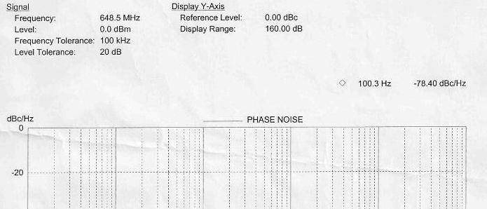
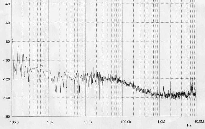
 However the area between 100Hz and 1 khz away from carrier shows significant change as the following")
12 The Crystal oscillator runs at 108 MHz and is multiplied by 6 times to 648 MHz. There is at least 15.5 db extra noise added because of this multiplying process This was taken via a Spectrum Analyser with Phase Noise Capabilities and results are probably compromised by the limitations of the instrument (1 khz to 100 khz or more) However the area between 100Hz and 1 khz away from carrier shows significant change as the following slide shows. 12
13 13
14 Oscillator heater Original configuration had voltage gain of 50 to 100 times, ~ 0.03 degree (1 ohm) change gave ~ 0.25 volt swing on output. Very touchy!! This circuit now has similarities to the circuit used by G8ACE in his OCXO s 14
15 Green is temperature of crystal. Blue is temperature inside Peltier chamber. Pink is drift of oscillator output. 15


16 Green is temperature of crystal. Blue is temperature inside Peltier chamber. Pink is drift of oscillator output. Insufficient time during warmup period caused upward slope. 16
17 Block diagram of Beacon 17
18 Discussion of functional blocks Oscillator The oscillator is to be configured, so that ~ 100 ~ 0dBm is present on the output of the EME65B PCB. This allows replacement with units such as the G8ACE unit, and reduces interaction between oscillator and multipliers. There is some small frequency control, using a varicap, to allow for frequency adjustment, due to crystal aging, or to allow disciplining. Regulators off the Oscillator enclosure, so that only heating is done by the W6PQL unit. 108 to 648 MHz multiplier Another modified EME65B (ie minus the crystal) is used as the 108 to 648 frequency multiplier. The modifications as discussed before are still mostly applicable to reduce noise and improve voltage stability. Small attenuator Pad to reduce level. 648 to 1296 MHz multiplier Uses ERA-3 MMIC, on a Waikato VHF Group filter PCB. (~ +7 dbm or 5 mw) 18

19 Discussion of functional blocks Attenuator/Pin switch This first attenuator is used to set drive levels for the subsequent stages. A PIN switch is keyed to reduce drive level in the off state, and additionally it ensures that the following active stages don t have RF on them, during keying. There is another attenuator on the output of the switch, to reduce the output impedance change when the PIN switch is keyed. 1 Watt Amp The Minikits EME162 Amplifier allows a drive stage to be added, and in this application, a ERA-2 MMIC was added for additional gain. There is some minor changes to increase volts on the Output FET slightly. Power output in excess of +29 dbm. These 2 stages are switched on and off by the keying. Cooling is by a stick on heatsink. This could be used as the final stage, however for more power Image Copyright Mini-kits 19
20 Discussion of functional blocks Output Amplifier The RF Device could be either a Mitsubishi MGF0907 or Toshiba FLL watt FET. (available at low(ish) cost on the surplus market) Positive DC Supply was going to keyed with DC current set to ~ 2A, but changed so that device is biased in Class AB, and driven up with RF Drive. Greater efficiency than a Mitsubishi Power Module.(~ 50 % vs 25 %! ) Will have PSU interlock so will not put Drain Volts on without 5 volts, otherwise FET will very quickly become a 3 legged fuse. NOTE Mitsubishi DO NOT recommend frequent ON-OFF keying of their power modules LDMOS FET s and surplus amplifiers are becoming available as well. Circulator and Bandpass filter (BPF) I have circulators and BPF s from surplus equipment. The circulators will retune to 1296 MHz, with strong magnet from faulty PC Hard-drive. The BPF s have multipole construction, and tunable notches that can reduce adjacent 108 MHz products further. 20
programmed via a PC Serial Bus Features :- Variable keying speed Programmable delay Audio (MCW),CW and PTT Outputs Also")
21 Discussion of functional blocks Keyer I was looking for a suitable keyer, with multiple features. I came across the ID-O-Matic, which can be (re)programmed via a PC Serial Bus Features :- Variable keying speed Programmable delay Audio (MCW),CW and PTT Outputs Also useful in Repeater Applications US$20 From N0XAS 21
22 Discussion of functional blocks Regulators Most of the regulators are conventional 7808 or 7805 regulators, however the regulator for the PA, will be LDO (Low Drop Out), due to higher voltage (10v). The current requirements are higher so a LM1085 3A version, or LM1084 5A version is selected. Ensure adequate heatsinking. I have seen regulators show thermal shutdown, if run for long periods of time (15 to 30mins) 22


23 Additions Used GPS Disciplined Oscillators (GPSDO) such as the Trimble Thunderbolt shown left can be used in a Oscillator locking scheme such as suggested by G4JNT ( see figure 3. The use of a DDS like that by Mini-kits will be necessary in this application. Alternatives are REFLOCK units by CT1DMK and VE1ALQ Note this project is a work in progress. Kevin ZL1UJG 23
VHF,UHF and SHF TRANSVERTERS. by Kevin Murphy ZL1UJG
 VHF,UHF and SHF TRANSVERTERS by Kevin Murphy ZL1UJG 1 Topics in Presentation History of Transverters Generic design Band by band analysis:- What transverters are available (commercial :- new and used,
SPECIFICATIONS: Subcarrier Frequency 5.5MHz adjustable, FM Modulated +/- 50KHz. 2nd 11MHz >40dB down from 5.5MHz
 Mini-kits AUDIO / SUBCARRIER KIT EME75 Version4 SPECIFICATIONS: Subcarrier Frequency 5.5MHz adjustable, FM Modulated +/- 50KHz Subcarrier Output 1.5v p-p Output @ 5.5MHz DESCRIPTION & FEATURES: The Notes
1665 MHz Radio Astronomy Receiver Part 1. Kevin Murphy ZL1UJG Tom Bevan ZL1THG Robin Holdsworth ZL1IC
 1665 MHz Radio Astronomy Receiver 2006 Part 1 Kevin Murphy ZL1UJG Tom Bevan ZL1THG Robin Holdsworth ZL1IC 1 1665 MHz Radio Astronomy Receiver July 2006 Kevin Murphy Tom Bevan Robin Holdsworth ZL1UJG ZL1THG
AIRY V.H.F. RADIO CLUB, INC.
 Mt. AIRY V.H.F. RADIO CLUB, INC. W3CCX CLUB MEMORIAL CALL ARRL Affiliated Club Volume L June 2009 Number 6 PREZ SEZ: In the blink of an eye, five years has flown by since I got the call from Doc W3GAD,
The 144MHz Anglian 3 transverter
 The 144MHz Anglian 3 transverter A high performance 144/28MHz transverter G4DDK document issue 1 12/9/16 Introduction Anglian 3 is an update to the 144MHz Anglian 2 transverter. The Anglian 2 is no longer
Demo Circuit DC550A Quick Start Guide.
 May 12, 2004 Demo Circuit DC550A. Introduction Demo circuit DC550A demonstrates operation of the LT5514 IC, a DC-850MHz bandwidth open loop transconductance amplifier with high impedance open collector
PA FAN PLATE ASSEMBLY 188D6127G1 SYMBOL PART NO. DESCRIPTION. 4 SBS /10 Spring nut. 5 19A702339P510 Screw, thread forming, flat head.
 MAINTENANCE MANUAL 851-870 MHz, 110 WATT POWER AMPLIFIER 19D902797G5 TABLE OF CONTENTS Page DESCRIPTION.............................................. Front Page SPECIFICATIONS.................................................
RF and Optical Bolometer
 RF and Optical Bolometer When RF energy is delivered to a resistive load it dissipates heat. If the load has a relatively poor thermal coupling to its surrounding environment its temperature will rise.
LBI-30398N. MAINTENANCE MANUAL MHz PHASE LOCK LOOP EXCITER 19D423249G1 & G2 DESCRIPTION TABLE OF CONTENTS. Page. DESCRIPTION...
 MAINTENANCE MANUAL 138-174 MHz PHASE LOCK LOOP EXCITER 19D423249G1 & G2 LBI-30398N TABLE OF CONTENTS DESCRIPTION...Front Cover CIRCUIT ANALYSIS... 1 MODIFICATION INSTRUCTIONS... 4 PARTS LIST AND PRODUCTION
Silicon-Carbide High Efficiency 145 MHz Amplifier for Space Applications
 Silicon-Carbide High Efficiency 145 MHz Amplifier for Space Applications By Marc Franco, N2UO 1 Introduction This paper describes a W high efficiency 145 MHz amplifier to be used in a spacecraft like AMSAT
APPLICATION NOTE dBm PA and PA Predriver with 37% Efficiency for 2.4GHz FHSS WLAN Applications
 Maxim > App Notes > WIRELESS, RF, AND CABLE Keywords: rf, pa, bluetooth, 2.4ghz wireless, rfic, wlan, fhss, lna, rf ics May 01, 2001 APPLICATION NOTE 584 +23dBm PA and PA Predriver with 37% Efficiency
ERICSSONZ LBI-30398P. MAINTENANCE MANUAL MHz PHASE LOCKED LOOP EXCITER 19D423249G1 & G2 DESCRIPTION TABLE OF CONTENTS
 MAINTENANCE MANUAL 138-174 MHz PHASE LOCKED LOOP EXCITER 19D423249G1 & G2 TABLE OF CONTENTS Page DESCRIPTION... Front Cover CIRCUIT ANALYSIS...1 MODIFICATION INSTRUCTIONS...4 PARTS LIST...5 PRODUCTION
Handbook / Kit. DB 6 NT 5,7 GHz Transverter MK DB 6 NT
 Handbook / Kit DB 6 NT 5,7 GHz Transverter MK2 4.2003 DB 6 NT 5,7 GHz Transverter MK2 DB6NT 4.2003 3. Generation Indroduction In 1977 the DUBUS magazine published the first 5,7GHz SSB transverter which
Phy 335, Unit 4 Transistors and transistor circuits (part one)
") Mini-lecture topics (multiple lectures): Phy 335, Unit 4 Transistors and transistor circuits (part one) p-n junctions re-visited How does a bipolar transistor works; analogy with a valve Basic circuit
Mini-lecture topics (multiple lectures): Phy 335, Unit 4 Transistors and transistor circuits (part one) p-n junctions re-visited How does a bipolar transistor works; analogy with a valve Basic circuit
MAINTENANCE MANUAL TRANSMITTER/RECEIVER BOARD CMN-234A/B FOR MLSU141 & MLSU241 UHF MOBILE RADIO TABLE OF CONTENTS
 MAINTENANCE MANUAL TRANSMITTER/RECEIVER BOARD CMN-234A/B FOR MLSU141 & MLSU241 UHF MOBILE RADIO TABLE OF CONTENTS DESCRIPTION... 2 CIRCUIT ANALYSIS... 2 TRANSMITTER... 2 9-Voft Regulator... 2 Exciter...
Maintenance Manual LBI-38531G MHz, 110 WATT POWER AMPLIFIER 19D902797G1 DESCRIPTION TABLE OF CONTENTS
 Maintenance Manual LBI-38531G 136-174 MHz, 110 WATT POWER AMPLIFIER 19D902797G1 TABLE OF CONTENTS Page DESCRIPTION.............................................. Front Cover SPECIFICATIONS.................................................
Third-Method Narrowband Direct Upconverter for the LF / MF Bands
 Third-Method Narrowband Direct Upconverter for the LF / MF Bands Introduction Andy Talbot G4JNT February 2016 Previous designs for upconverters from audio generated from a soundcard to RF have been published
Components for modular microwave transverters. Wolf-Henning Rech DF9IC in JN48iw
 Components for modular microwave transverters Wolf-Henning Rech DF9IC in JN48iw http://www.df9ic.de Content Multiband transverter systems Filters and multiplexers PLL-disciplined oscillators Transverters
Low voltage high performance mixer FM IF system
 DESCRIPTION The is a low voltage high performance monolithic FM IF system incorporating a mixer/oscillator, two limiting intermediate frequency amplifiers, quadrature detector, logarithmic received signal
Single Conversion LF Upconverter Andy Talbot G4JNT Jan 2009
 Single Conversion LF Upconverter Andy Talbot G4JNT Jan 2009 Mark 2 Version Oct 2010, see Appendix, Page 8 This upconverter is designed to directly translate the output from a soundcard from a PC running
AVL-10000T AUDIO VIDEO LINK TRANSMITTER TECHNICAL MANUAL
 AVL-10000T AUDIO VIDEO LINK TRANSMITTER TECHNICAL MANUAL Document : AVL-10000T Version: 1.00 Author: Henry S Date: 25 July 2008 This module contains protection circuitry to guard against damage due to
INC. MICROWAVE. A Spectrum Control Business
 DRO Selection Guide DIELECTRIC RESONATOR OSCILLATORS Model Number Frequency Free Running, Mechanically Tuned Mechanical Tuning BW (MHz) +10 MDR2100 2.5-6.0 +10 6.0-21.0 +20 Free Running, Mechanically Tuned,
CUSTOM INTEGRATED ASSEMBLIES
 17 CUSTOM INTEGRATED ASSEMBLIES CUSTOM INTEGRATED ASSEMBLIES Cougar offers full first-level integration capabilities, providing not just performance components but also full subsystem solutions to help
ericssonz LBI-38640E MAINTENANCE MANUAL FOR VHF TRANSMITTER SYNTHESIZER MODULE 19D902780G1 DESCRIPTION
 MAINTENANCE MANUAL FOR VHF TRANSMITTER SYNTHESIZER MODULE 19D902780G1 TABLE OF CONTENTS Page DESCRIPTION........................................... Front Cover GENERAL SPECIFICATIONS...................................
MAINTENANCE MANUAL RF BOARD 19D901835G1 ( MHz) 19D901835G2 ( MHz) FOR MVS
 19D901835G2 ( MHz) FOR MVS") D MAINTENANCE MANUAL F BOAD 19D901835G1 (136-153 MHz) 19D901835G2 (150-174 MHz) FO MVS TABLE OF CONTENTS DESCIPTION............................................... Front Cover CICUIT ANALYSIS..............................................
D MAINTENANCE MANUAL F BOAD 19D901835G1 (136-153 MHz) 19D901835G2 (150-174 MHz) FO MVS TABLE OF CONTENTS DESCIPTION............................................... Front Cover CICUIT ANALYSIS..............................................
A Testbench for Analysis of Bias Network Effects in an RF Power Amplifier with DPD. Marius Ubostad and Morten Olavsbråten
 A Testbench for Analysis of Bias Network Effects in an RF Power Amplifier with DPD Marius Ubostad and Morten Olavsbråten Dept. of Electronics and Telecommunications Norwegian University of Science and
2m Weak Signal Sources January 2018
 2m Weak Signal Sources January 2018 Rick Campbell This white paper describes a set of signal sources at power levels from -30dBm to +12dBm in the 144 MHz amateur radio band. All are legal for direct connection
PRACTICE. Amateur Radio Operator Certificate Examination. Advanced Qualification
 Innovation, Science and Economic Development Canada Innovation, Sciences et Développement économique Canada Amateur Radio Operator Certificate Examination Advanced Qualification 2018-06-30 To pass this
Maintenance Manual TRANSMITTER/RECEIVER BOARD CMN-233 FOR MLSH041
 Maintenance Manual TRANSMITTER/RECEIVER BOARD CMN-233 FOR MLSH041 TABLE OF CONTENTS Page DESCRIPTION... 2 CIRCUIT ANALYSIS... 2 Transmitter... 2 9-volt Regulator... 2 Exciter... 2 40-Watt PA... 2 Antenna
INPUT: 110/220VAC. Parallel Input Series Input Parallel Output Series Output (W/CT)
") Linear power supply design: To make a simple linear power supply, use a transformer to step down the 120VAC to a lower voltage. Next, send the low voltage AC through a rectifier to make it DC and use a
Linear power supply design: To make a simple linear power supply, use a transformer to step down the 120VAC to a lower voltage. Next, send the low voltage AC through a rectifier to make it DC and use a
Handbook / Kit. DB 6 NT 2,3 GHz Transverter MK DB 6 NT
 Handbook / Kit DB 6 NT 2,3 GHz Transverter MK2 4.2003 DB 6 NT 2.3 GHz Transverter MK2 DB6NT 4.2003 Introduction This transverter is a further development of the schematic published in 1993. Technical data
Experimenting with a Stellex YIG Oscillator
 Overview Experimenting with a Stellex YIG Oscillator Stellex 6755 726 (Endwave MY01210) tunable mini YIG oscillators are starting to show up on Ebay for around $20 to $40. Most of these YIGs cover the
A 3 Watt LDMOS Driver for the 432MHz band
 A 3 Watt LDMOS Driver for the 432MHz band John C Worsnop. PhD CEng MIET, G4BAO Introduction The popularity of my 2.5-Watt driver kit for the 1296MHz band (1) and the recent publication of G4DDK s Iceni
Datasheet SHF 100 BPP
 SHF Communication Technologies AG Wilhelm-von-Siemens-Str. 23D 12277 Berlin Germany Phone ++49 30 / 772 05 10 Fax ++49 30 / 753 10 78 E-Mail: sales@shf.de Web: http://www.shf.de Datasheet SHF 100 BPP Broadband
Rethinking The Role Of phemt Cascode Amplifiers In RF Design
 Guest Column February 10, 2014 Rethinking The Role Of phemt Cascode Amplifiers In RF Design By Alan Ake, Skyworks Solutions, Inc. I consider myself fortunate that, as a fresh-out-of-school EE, I was able
VHF Super-Regenerative Receiver
 VHF Super-Regenerative Receiver I have started straight with the circuit out of the ARRL handbook, by Charles Kitchen N1TEV. I didn't have a 6v8 zener, or a few other part values, so I had to substitute
Radio Receivers. Al Penney VO1NO
 Radio Receivers Role of the Receiver The Antenna must capture the radio wave. The desired frequency must be selected from all the EM waves captured by the antenna. The selected signal is usually very weak
A Low Noise Amplifier with HF Selectivity
 A Low Noise Amplifier with HF Selectivity Johan Karlsson Mikael Grudd Radio project 2008 Department of Electrical and Information Technology Lund University Supervisor: Göran Jönsson Abstract This report
MGA GHz 3 V, 17 dbm Amplifier. Data Sheet. Features. Description. Applications. Surface Mount Package. Simplified Schematic
 MGA-853.1 GHz 3 V, 17 dbm Amplifier Data Sheet Description Avago s MGA-853 is an economical, easy-to-use GaAs MMIC amplifier that offers excellent power and low noise figure for applications from.1 to
The Aleph 5 is a stereo 60 watt audio power amplifier which operates in single-ended class A mode.
 Pass Laboratories Aleph 5 Service Manual Rev 0 9/20/96 Aleph 5 Service Manual. The Aleph 5 is a stereo 60 watt audio power amplifier which operates in single-ended class A mode. The Aleph 5 has only two
Building a Bitx20 Version 3
 Building a Bitx20 Version 3 The board can be broken into sections and then built and tested one section at a time. This will make troubleshooting easier as any problems will be confined to one small section.
Updating KK7B, SHF,DEM or DEMI 900 and 1296 MHz. transverters
 Updating KK7B, SHF,DEM or DEMI 900 and 1296 MHz. transverters By Steve Kostro, N2CEI PREFACE: Yes, It may be hard to believe, but the original 900 and 1296 No-Tune transverter concepts have been around
Varactor-Tuned Oscillators. Technical Data. VTO-8000 Series
 Varactor-Tuned Oscillators Technical Data VTO-8000 Series Features 600 MHz to 10.5 GHz Coverage Fast Tuning +7 to +13 dbm Output Power ± 1.5 db Output Flatness Hermetic Thin-film Construction Description
RefLocking DEMI Microwave Transverters
 RefLocking DEMI Microwave Transverters Steven Kerns - N3FTI Abstract For many years amateurs have been utilizing PLL (Phase Lock Loop) systems to stabilize their microwave local oscillators to a highly
High performance low power mixer FM IF system
 DESCRIPTION The is a high performance monolithic low-power FM IF system incorporating a mixer/oscillator, two limiting intermediate frequency amplifiers, quadrature detector, muting, logarithmic received
Directly Synthesized 47 GHz Local Oscillator. Garry C. Hess, K3SIW February 18, 2007
 Directly Synthesized 47 GHz Local Oscillator Garry C. Hess, K3SIW February 18, 2007 Introduction. This note describes a means of directly synthesizing the local oscillator for a 47 GHz transverter. The
LM389 Low Voltage Audio Power Amplifier with NPN Transistor Array
 LM389 Low Voltage Audio Power Amplifier with NPN Transistor Array General Description The LM389 is an array of three NPN transistors on the same substrate with an audio power amplifier similar to the LM386
HF Receivers, Part 2
 HF Receivers, Part 2 Superhet building blocks: AM, SSB/CW, FM receivers Adam Farson VA7OJ View an excellent tutorial on receivers NSARC HF Operators HF Receivers 2 1 The RF Amplifier (Preamp)! Typical
RADIO RECEIVERS ECE 3103 WIRELESS COMMUNICATION SYSTEMS
 RADIO RECEIVERS ECE 3103 WIRELESS COMMUNICATION SYSTEMS FUNCTIONS OF A RADIO RECEIVER The main functions of a radio receiver are: 1. To intercept the RF signal by using the receiver antenna 2. Select the
AT General Purpose, Low Current NPN Silicon Bipolar Transistor. Data Sheet
 AT-4532 General Purpose, Low Current NPN Silicon Bipolar Transistor Data Sheet Description Avago s AT-4532 is a general purpose NPN bipolar transistor that has been optimized for maximum f t at low voltage
Glossary of VCO terms
 Glossary of VCO terms VOLTAGE CONTROLLED OSCILLATOR (VCO): This is an oscillator designed so the output frequency can be changed by applying a voltage to its control port or tuning port. FREQUENCY TUNING
1. What is the unit of electromotive force? (a) volt (b) ampere (c) watt (d) ohm. 2. The resonant frequency of a tuned (LRC) circuit is given by
 volt (b) ampere (c) watt (d) ohm. 2. The resonant frequency of a tuned (LRC) circuit is given by") Department of Examinations, Sri Lanka EXAMINATION FOR THE AMATEUR RADIO OPERATORS CERTIFICATE OF PROFICIENCY ISSUED BY THE DIRECTOR GENERAL OF TELECOMMUNICATIONS, SRI LANKA 2004 (NOVICE CLASS) Basic Electricity,
Department of Examinations, Sri Lanka EXAMINATION FOR THE AMATEUR RADIO OPERATORS CERTIFICATE OF PROFICIENCY ISSUED BY THE DIRECTOR GENERAL OF TELECOMMUNICATIONS, SRI LANKA 2004 (NOVICE CLASS) Basic Electricity,
G6ALU 20W FET PA Construction Information
 G6ALU 20W FET PA Construction Information The requirement This amplifier was designed specifically to complement the Pic-A-Star transceiver developed by Peter Rhodes G3XJP. From the band pass filter an
Keywords: ISM, RF, transmitter, short-range, RFIC, switching power amplifier, ETSI
 Maxim > Design Support > Technical Documents > Application Notes > Wireless and RF > APP 4929 Keywords: ISM, RF, transmitter, short-range, RFIC, switching power amplifier, ETSI APPLICATION NOTE 4929 Adapting
CX7 Troubleshooting Index
 CX7 Troubleshooting Index Modification S/1 Newsletter Guide Board Description A/TO A/TO MODE Intermod V1,12 P4.4 A11 Shut off one 35 MHz osc in receive, done sn 244 A/TO Spur V1,12 P1 Reduce A/TO spur,
The ROSE 80 CW Transceiver (Part 1 of 3)
") Build a 5 watt, 80 meter QRP CW Transceiver!!! Page 1 of 10 The ROSE 80 CW Transceiver (Part 1 of 3) Build a 5 watt, 80 meter QRP CW Transceiver!!! (Designed by N1HFX) A great deal of interest has been
Build a 5 watt, 80 meter QRP CW Transceiver!!! Page 1 of 10 The ROSE 80 CW Transceiver (Part 1 of 3) Build a 5 watt, 80 meter QRP CW Transceiver!!! (Designed by N1HFX) A great deal of interest has been
The G4EGQ RAE COURSE Lesson 9 Transmitters Lesson 8 looked at a simple transmitter exciter comprising of oscillator, buffer and multiplier stages.
 Lesson 8 looked at a simple transmitter exciter comprising of oscillator, buffer and multiplier stages. The power amplifier The output from the exciter is usually very low and it is necessary to amplify
Medium Power 137kHz Linear Power Amplifier G4JNT Sept 2010
 Medium Power 137kHz Linear Power Amplifier G4JNT Sept 2010 This project was conceived on the back of an envelope after running a WSPR beacon thorough my 600 Watt switch mode Power Amplifier, and setting
Surface Mount SOT-363 (SC-70) Package. Pin Connections and Package Marking GND. V dd. Note: Package marking provides orientation and identification.
 Package. Pin Connections and Package Marking GND. V dd. Note: Package marking provides orientation and identification.") GHz V Low Current GaAs MMIC LNA Technical Data MGA-876 Features Ultra-Miniature Package.6 db Min. Noise Figure at. GHz. db Gain at. GHz Single + V or V Supply,. ma Current Applications LNA or Gain Stage
GHz V Low Current GaAs MMIC LNA Technical Data MGA-876 Features Ultra-Miniature Package.6 db Min. Noise Figure at. GHz. db Gain at. GHz Single + V or V Supply,. ma Current Applications LNA or Gain Stage
EVALUATION KIT AVAILABLE 10MHz to 1050MHz Integrated RF Oscillator with Buffered Outputs. Typical Operating Circuit. 10nH 1000pF MAX2620 BIAS SUPPLY
 19-1248; Rev 1; 5/98 EVALUATION KIT AVAILABLE 10MHz to 1050MHz Integrated General Description The combines a low-noise oscillator with two output buffers in a low-cost, plastic surface-mount, ultra-small
New Temperature Control for the 2nd LO (VFO) Box
 Box") Illustration DARC, danke! Siemens E311b Shortwave Receiver New Temperature Control for the 2nd LO (VFO) Box Note: this electronic temperature controller can easily be used in other applications! Page 1/6
Illustration DARC, danke! Siemens E311b Shortwave Receiver New Temperature Control for the 2nd LO (VFO) Box Note: this electronic temperature controller can easily be used in other applications! Page 1/6
CHARACTERIZATION OF OP-AMP
 EXPERIMENT 4 CHARACTERIZATION OF OP-AMP OBJECTIVES 1. To sketch and briefly explain an operational amplifier circuit symbol and identify all terminals. 2. To list the amplifier stages in a typical op-amp
Construction Manual 4m-Linear-Transverter XV4-15
 Construction Manual 4m-Linear-Transverter XV4-15 Holger Eckardt DF2FQ Kirchstockacherstr. 33 D-85662 Hohenbrunn 3207 Technical data exciter frequency: 21.0... 21.5 MHz RF frequency: 70.0.. 70.5 MHz supply
Figure 2 shows the actual schematic for the power supply and one channel.
 Pass Laboratories Aleph 3 Service Manual rev 0 2/1/96 Aleph 3 Service Manual. The Aleph 3 is a stereo 30 watt per channel audio power amplifier which operates in single-ended class A mode. The Aleph 3
Data Sheet AMMC GHz Output 2 Active Frequency Multiplier. Description. Features. Applications
 AMMC-1 GHz Output Active Frequency Multiplier Data Sheet Chip Size: x µm ( x mils) Chip Size Tolerance: ± µm (±. mils) Chip Thickness: ± µm ( ±. mils) Pad Dimensions: 1 x µm (x3 ±. mils) Description Avago
Application Note 5011
 MGA-62563 High Performance GaAs MMIC Amplifier Application Note 511 Application Information The MGA-62563 is a high performance GaAs MMIC amplifier fabricated with Avago Technologies E-pHEMT process and
LBI-38642B. MAINTENANCE MANUAL RECEIVER FRONT END MODULE 19D902782G1: MHz 19D902782G2: MHz DESCRIPTION TABLE OF CONTENTS
 LBI-38642B MAINTENANCE MANUAL RECEIVER FRONT END MODULE 19D902782G1: 136-151 MHz 19D902782G2: 150-174 MHz TABLE OF CONTENTS Page DESCRIPTION............................................... Front Cover SPECIFICATIONS.............................................
The Aleph 2 is a monoblock 100 watt audio power amplifier which operates in single-ended class A mode.
 Pass Laboratories Aleph 2 Service Manual Rev 0 2/1/96 Aleph 2 Service Manual. The Aleph 2 is a monoblock 100 watt audio power amplifier which operates in single-ended class A mode. The Aleph 2 has only
HF Power Amplifier (Reference Design Guide) RFID Systems / ASP
 RFID Systems / ASP") 16 September 2008 Rev A HF Power Amplifier (Reference Design Guide) RFID Systems / ASP 1.) Scope Shown herein is a HF power amplifier design with performance plots. As every application is different and
16 September 2008 Rev A HF Power Amplifier (Reference Design Guide) RFID Systems / ASP 1.) Scope Shown herein is a HF power amplifier design with performance plots. As every application is different and
PART MAX2605EUT-T MAX2606EUT-T MAX2607EUT-T MAX2608EUT-T MAX2609EUT-T TOP VIEW IND GND. Maxim Integrated Products 1
 19-1673; Rev 0a; 4/02 EVALUATION KIT MANUAL AVAILABLE 45MHz to 650MHz, Integrated IF General Description The are compact, high-performance intermediate-frequency (IF) voltage-controlled oscillators (VCOs)
Modifying the Qualcomm 1W Ku-Band PA for use on 3.4, 5.7 or 10.3 GHz
 Web Version 10-9-2001 Modifying the Qualcomm 1W Ku-Band PA for use on 3.4, 5.7 or 10.3 GHz K-Banke- 07/13/01 Hundreds of Ku-Band Qualcomm 1 watt power amplifiers have been modified and found their way
Tuned Radio Frequency Receiver (TRF) The most elementary receiver design, consisting of RF amplifier stages, detector and audio amplifier stages.
 The most elementary receiver design, consisting of RF amplifier stages, detector and audio amplifier stages.") Figure 3-1 Simple radio receiver block diagram. Tuned Radio Frequency Receiver (TRF) The most elementary receiver design, consisting of RF amplifier stages, detector and audio amplifier stages. Jeffrey
Figure 3-1 Simple radio receiver block diagram. Tuned Radio Frequency Receiver (TRF) The most elementary receiver design, consisting of RF amplifier stages, detector and audio amplifier stages. Jeffrey
DEM Part Number L144-28INTCK 144 MHz Transverter Kit and complete kit
 DEM Part Number L144-28INTCK 144 MHz Transverter Kit and complete kit Power Out: Noise Figure and Gain: DC Power Requirement: 50 mw linear minimum 3.5 db NF nominal, 5 dbg maximum 12-15.5 VDC, 13.8 nominal
ericssonz LBI-38642C MAINTENANCE MANUAL RECEIVER FRONT END MODULE 19D902782G1: MHz 19D902782G2: MHz DESCRIPTION TABLE OF CONTENTS
 LBI-38642C MAINTENANCE MANUAL RECEIVER FRONT END MODULE 19D902782G1: 136-151 MHz 19D902782G2: 150-174 MHz TABLE OF CONTENTS Page DESCRIPTION............................................... Front Cover SPECIFICATIONS.............................................
Calibration Techniques for the Home Lab
 Calibration Techniques for the Home Lab Jacques Audet VE2AZX jacaudet@videotron.ca Web: ve2azx.net September 2018 ve2azx.net 1 Summary - Using a reference multimeter as a calibrator for less accurate instruments.
***note: pallet may draw up to 5.0 amps on a 32V supply.
 Model BCI-UHF-40TX12 TV Pallet Amplifier Module This amplifier module is ideal for final output stages in analog and digital TV broadcast equipment. 470 860MHz 28-32 Volts Pout: 25W Peak Sync. 10Watts
Locked VCXOs for Stable Microwave Local Oscillators with Low Phase Noise
 Locked VCXOs for Stable Microwave Local Oscillators with Low Phase Noise Paul Wade W1GHZ 2013 w1ghz@arrl.net A good local oscillator has been a perennial problem for microwave operators. An ideal LO would
VHF LAND MOBILE SERVICE
 RFS21 December 1991 (Issue 1) SPECIFICATION FOR RADIO APPARATUS: VHF LAND MOBILE SERVICE USING AMPLITUDE MODULATION WITH 12.5 khz CARRIER FREQUENCY SEPARATION Communications Division Ministry of Commerce
Application Notes High Performance Audio Amplifiers
 High Performance Audio Amplifiers Exicon Lateral MOSFETs These audio devices are capable of very high standards of amplification, with low distortion and very fast slew rates. They are free from secondary
Alcatel White Box 24GHz Transceiver experiments and modifications
 Alcatel White Box 24GHz Transceiver experiments and modifications A set of working notes, measurements and comments PSU Need to supply : -5V up to ~ 30mA for Rx and PA modules +5.2V 1A for Rx and Tx mixer
CLD Application Notes Connection Options
 CLD Application Notes Connection Options Series Higher voltages may be obtained by connecting identical CLDs in series (Figure 4). Voltage balancing resistors are recommended. Since the resistors shunt
1 FUNCTIONAL DESCRIPTION WAY SPLITTER/INPUT BOARD FET RF AMPLIFIERS WAY POWER COMBINER VSWR CONTROL BOARD...
 CONTENTS 1 FUNCTIONAL DESCRIPTION...1 2 4-WAY SPLITTER/INPUT BOARD...2 3 FET RF AMPLIFIERS...3 4 4-WAY POWER COMBINER...4 5 VSWR CONTROL BOARD...5 6 ADJUSTMENT OF BIAS VOLTAGE TO ESTABLISH PROPER QUIESCENT
Broadcast Concepts Inc NW 102 Road Suite 4 Medley FL Tel: : Fax Model P50FM42MH-SMA2 FM Pallet Amplifier Module
 Model P50FM42MH-SMA2 FM Pallet Amplifier Module This amplifier module is ideal for driver stages in FM Broadcast transmitters. 86 110MHz 28Volts Pout: 50W CW minimum 40dB Gain Class AB MACOM MRF173 Mosfet
California Eastern Laboratories
 California Eastern Laboratories AN143 Design of Power Amplifier Using the UPG2118K APPLICATION NOTE I. Introduction Renesas' UPG2118K is a 3-stage 1.5W GaAs MMIC power amplifier that is usable from approximately
HF Receivers, Part 3
 HF Receivers, Part 3 Introduction to frequency synthesis; ancillary receiver functions Adam Farson VA7OJ View an excellent tutorial on receivers Another link to receiver principles NSARC HF Operators HF
onlinecomponents.com FET Circuit Applications FET Circuit Applications AN-32 National Semiconductor Application Note 32 February 1970
 FET Circuit Applications National Semiconductor Application Note 32 February 1970 Polycarbonate dielectric Sample and Hold With Offset Adjustment TL H 6791 1 Long Time Comparator TL H 6791 2 The 2N4393
A HIGH PRECISION QUARTZ OSCILLATOR WITH PERFORMANCE COMPARABLE TO RUBIDIUM OSCILLATORS IN MANY RESPECTS
 A HIGH PRECISION QUARTZ OSCILLATOR WITH PERFORMANCE COMPARABLE TO RUBIDIUM OSCILLATORS IN MANY RESPECTS Manish Vaish MTI-Milliren Technologies, Inc. Two New Pasture Road Newburyport, MA 195 Abstract An
1.9GHz Power Amplifier
 EVALUATION KIT AVAILABLE MAX2248 General Description The MAX2248 single-supply, low-voltage power amplifier (PA) IC is designed specifically for applications in the 188MHz to 193MHz frequency band. The
MGA GHz 3 V, 17 dbm Amplifier. Data Sheet
 MGA-853.1 GHz 3 V, 17 dbm Amplifier Data Sheet Description Avago s MGA-853 is an economical, easy-to-use GaAs MMIC amplifier that offers excellent power and low noise figure for applications from.1 to
AMMC GHz Output x2 Active Frequency Multiplier
 AMMC-614 2 4 GHz Output x2 Active Frequency Multiplier Data Sheet Chip Size: Chip Size Tolerance: Chip Thickness: Pad Dimensions: 13 x 9 µm (1 x 3 mils) ±1 µm (±.4 mils) 1 ± 1 µm (4 ±.4 mils) 12 x 8 µm
HAMTRONICS LPA 2-25R REPEATER POWER AMPLIFIER: ASSEMBLY, INSTALLATION, & MAINTENANCE
 HAMTRONICS LPA 2-25R REPEATER POWER AMPLIFIER: ASSEMBLY, INSTALLATION, & MAINTENANCE GENERAL INFORMATION. The Power Amplifier is a class C device designed to be installed as an integral part of a transmitter
Varactor-Tuned Oscillators. Technical Data. VTO-8000 Series. Pin Configuration TO-8V
 H Varactor-Tuned Oscillators Technical Data VTO-8 Series Features 6 MHz to.5 Coverage Fast Tuning +7 to + dbm Output Power ±1.5 db Output Flatness Hermetic Thin-film Construction Description HP VTO-8 Series
GaAs MMIC Non-Linear Transmission Line. Packag e. Refer to our website for a list of definitions for terminology presented in this table.
 GaAs MMIC Non-Linear Transmission Line NLTL-6273SM 1. Device Overview 1.1 General Description NLTL-6273SM is a MMIC non-linear transmission line (NLTL) based comb generator. This NLTL offers excellent
SOUTHERN AVIONICS COMPANY. SE125 Transmitter. SE125 Transmitter 1-1
 1-1 1 Introduction The SE Series transmitters are computer controlled systems designed around an embedded microprocessor. These systems are capable of remote monitoring and maintenance via Ethernet (optional).
3 Circuit Theory. 3.2 Balanced Gain Stage (BGS) Input to the amplifier is balanced. The shield is isolated
 Input to the amplifier is balanced. The shield is isolated") Rev. D CE Series Power Amplifier Service Manual 3 Circuit Theory 3.0 Overview This section of the manual explains the general operation of the CE power amplifier. Topics covered include Front End Operation,
Rev. D CE Series Power Amplifier Service Manual 3 Circuit Theory 3.0 Overview This section of the manual explains the general operation of the CE power amplifier. Topics covered include Front End Operation,
Chapter 6. FM Circuits
 Chapter 6 FM Circuits Topics Covered 6-1: Frequency Modulators 6-2: Frequency Demodulators Objectives You should be able to: Explain the operation of an FM modulators and demodulators. Compare and contrast;
SHF Communication Technologies AG
 SHF Communication Technologies AG Wilhelm-von-Siemens-Str. 23D 12277 Berlin Germany Phone ++49 30 / 772 05 10 Fax ++49 30 / 753 10 78 E-Mail: sales@shf.de Web: http://www.shf.de Datasheet SHF 806 E SHF
LM148/LM248/LM348 Quad 741 Op Amps
 Quad 741 Op Amps General Description The LM148 series is a true quad 741. It consists of four independent, high gain, internally compensated, low power operational amplifiers which have been designed to
IQ+ XT. 144Mhz SDR-RF Exciter (preliminar v0.1)
") IQ+ XT 144Mhz SDR-RF Exciter (preliminar v0.1) INTRODUCTION Since the IQ+ receiver was introduced one year ago several people ask if I have plans to produce an IQ+ transmitter. Initially I didn't plan
IQ+ XT 144Mhz SDR-RF Exciter (preliminar v0.1) INTRODUCTION Since the IQ+ receiver was introduced one year ago several people ask if I have plans to produce an IQ+ transmitter. Initially I didn't plan
87x. MGA GHz 3 V Low Current GaAs MMIC LNA. Data Sheet
 MGA-876 GHz V Low Current GaAs MMIC LNA Data Sheet Description Avago s MGA-876 is an economical, easy-to-use GaAs MMIC amplifier that offers low noise and excellent gain for applications from to GHz. Packaged