Handbook / Kit. DB 6 NT 2,3 GHz Transverter MK DB 6 NT
|
|
|
- Austen Hamilton
- 5 years ago
- Views:
Transcription


1 Handbook / Kit DB 6 NT 2,3 GHz Transverter MK DB 6 NT
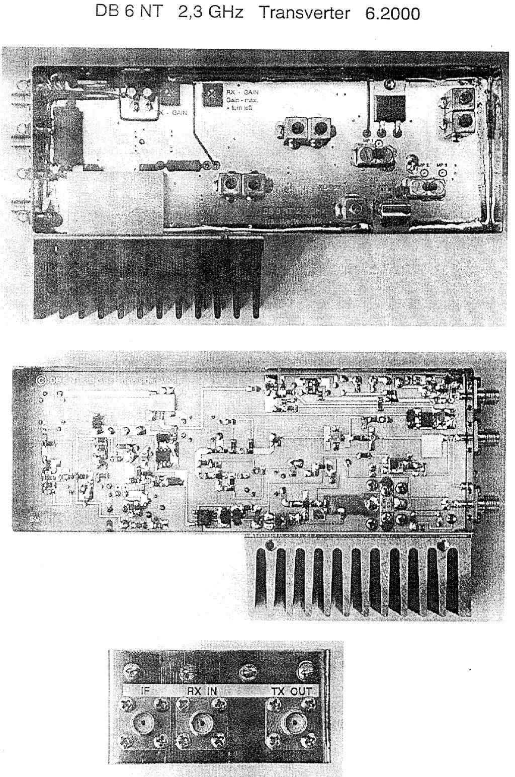
2 2.3 GHz Transverter MK2 DB6NT Introduction This transverter is a further development of the schematic published in Technical data of the assembly were further improved by the application of modern semiconductor devices. Redesign of the printed circuit board in respect to cooling of the high power devices improves the general performance of the transverter; its duplication has been further simplified. The circuitry has been laid out on a ceramic-filled epoxy substrate. The receiver section achieves a noise figure (NF) of less than 0.8 db at an amplification of more than 20 db. This eliminates the need for an external preamplifier. The transmitter section produces an output power >1W; suppression of spurious emissions is 60 db (typ.) while harmonics are being suppressed by 30 db (typ.). The transverter has been designed for the linear transfer of the 2 m band to the narrow band amateur section of the 13 cm band ( MHz); by some small modifications it may be tuned for the Oscar P3D frequency of MHz. 2 meter driving power can be adjusted from Watts; a change of a resistor will even allow a driving power of 10 mw. Driving power should not be too high; this avoids unnecessary heating of the IF-subassembly due to power dissipation. The entire transverter fits into a tinplate case measuring 60 x 150 x 30 mm. This includes IF switching, output control for coax-relays or final amplifier, crystal oscillator and local oscillator circuitry. No elaborate RF measuring equipment is needed for its alignment; a simple voltage measuring instrument will do. Description of circuitry The well proven Simple Quartz Oscillator with its FET SST310 operates at MHz. Frequency tuning is achieved by the brass slug in the oscillator coil. Application of relevant capacitors ( TK. Marked with * in the schematic ) will result a temperature compensation. Two capacitor soldering points have been provided for this feature. Stability should be sufficient for average working conditions. Should there be the need for an exact and highly stable frequency, an oven-controlled oscillator (DF9LN) with an output of approx. 1 mw may be connected to the circuitry at the marked location. For this change the original crystal must be removed. Following the oscillator is a tripler with a BFR92. A frequency of 362 MHz is being selected by a helix filter and then is being coupled into a tripler with a BFG93A. After an additional helix filter, which is to be tuned to 1088 MHz, the signal is being passed to a frequency doubler. After a helix filter with a final local oscillator (LO) frequency of 2176 MHz a LOpower of 5 mw is available. The IF signal is being passed through individually tunable attenuator pads for transmitter and receiver; switching occurs by PIN-diodes. Transmit/receive switching of the entire transverter is being controlled by a positive voltage during TX of the IF control cable; e.g. such a voltage is available at the output of the FT290R. Other transceivers need a small modification: connect a positive voltage, that is being generated within the transceiver during transmit mode, to the output connector via a 2K2 resistor. That s all! This type of control needs no additional control cables and has been well proven over the years. Naturally it is also possible to achieve conventional switchover with a PTT contact to ground. Switching of operating voltages within the transverter is being controlled by transistors. Switching voltage of the transmitter is being externally provided and may be used for the 1
3 control of coax-relays or final amplifiers (max. load 2 A). This output must be protected by a fine-wire fuse under all circumstances. The receiving section has a preamplifier stage with a HEMT - FET and an additional MMIC with a total amplification of >30 db. This eliminates the need for an additional IF-amplifier. The input signal is being coupled to a noise-adapted NE32584C via a 4.7 pf capacitor, The second stage with the MMIC - MGA86563 follows via the multi-layer ceramic filter F6. A RX- TX PIN diode switch is being followed by another helix filter F4 and the ring mixer. During transmit the TX-signal is being passed to a MMIC amplifier stage via the helix filter F4 following the mixer. The signal reaches a second MMIC ERA 5-SM after passing an additional helix filter F5 used for suppression of spurious emissions. The following final stage is equipped with a GaAs power FET MGF The transmitter output has a directional coupler with the Schottky-diode BAT62-03W. It facilitates monitoring of the output power (monitoring MON.) and supports the alignment of the circuitry. Construction: Experience in handling SMD-parts is absolutely essential. Under no circumstances should this become "a first" in working with SMD, as extremely small parts are being used. Also some basic knowledge concerning the construction of VHF circuits is desirable. Some parts, for example FET s, are very susceptible to static discharges. It is urgently recommended to adhere to ESD protective measures during construction. This incorporates a grounded and temperature controlled SMD-soldering station as well as a conductive and grounded workpad. Sequence of construction steps: a. Fitting of the printed circuit boards into the tinplate case by filing down the corners. b. Marking of the holes on the box for insertion of the SMA-coax connectors. c. Drilling of holes for connectors and feed-through capacitors. Tapping for M2 screws of the SMA-connectors. Shortening of SMA-connector pins to approx. 2.3 mm length. Mounting of SMA-connectors. d. Soldering of printed circuit boards into the case (see drawing) Solder all the way around! A 10.2 mm thick wooden board should be used as a support to achieve uniform positioning of the printed circuit board. e. Applying component parts and insertion of feed-through capacitors. Consult the component layout plan for soldering the helix filters. The cooling flange of the constant voltage regulator L4940V10 must be soldered to the tinplate case; its middle pin should be broken off. The FET BUZ 171 should be pressed all the way down onto the printed circuit board and its pins then be soldered. Otherwise there could be the possibility of the cooling flange causing a short at the lid of the case. 0.5 mm soldering wire should be used for the SMD components. After completion of the soldering the module should be washed in alcohol. Should an ultrasound cleaning device 2
4 be used, the crystal should be soldered into the circuitry after completion of the cleansing. (Crystals may be damaged by intense ultrasound.) Drying at 80 C for one hour in an oven or overnight on a warm heater element. f. Insertion of the cooling clock into the case and marking of the 2 holes that will later be used to hold the finned cooling block (drill diameter approx. 3.5 to 4 mm; smoothen the edges). Before bolting together, some heat conducting paste should be applied between cooling block, the wall of the case and the finned cooling block. Mounting the M3 x 25 mm hex screws as well as the four M2 x 4 mm screws around the final transistor should be done alternatively; any air gap between printed circuit board and the cooling block must be avoided. Some heat conducting paste should also be used when mounting the final transistor. Alignment: a. Applying of +12 V operating voltage by using a power supply with a 1 A (approx.) current limiter. Verifying of operating voltages at the constant voltage regulators. b. Measuring of the collector voltage of the BFR92 doubler at test point 1. Screw the brass slug into the oscillator coil -- use a paper strip for slug friction! When oscillation occurs the voltage should drop to approx. 7.2 V. c. Measuring of the voltage at test point 2. By alternatively tuning the 362 MHz band filter - F1-, a minimum voltage of approx. 6.2 V should be achieved (max. current = optimum drive). Should the ceramic screws be adjusted frequently, metal shavings will collect on their surface. An indication is a jumpy behavior when tuning. The coating can be removed with a fiber glass pen. d. Measuring of the voltage at test point 3. By alternatively tuning the 1088 MHz band filter -F2-, a minimum voltage of 6.6 V should be achieved (max. current = optimum drive). e. Screw in the brass tuning slugs according to the measurements given in the parts layout plan (Filter F3, F4 and F5). f. Connect a suitable antenna or a dummy load to the antenna connector of the receiver section. Measuring of the voltage at the drain of preamp transistor NE32584C and adjustment to approx. 2 V by the 1 K potentiometer at the gate of the FET s. g. Connect a 2 m receiver in SSB mode to the IF output. Potentiometers for RX- and TXgain should be in the full counter-clockwise position (max. amplification). An increase in noise level should be heard in the 2 m receiver. Maximum noise and thereby maximum receiver amplification should be achieved by alternative tuning of helix filter F4. Afterwards LO-filter F3 should be adjusted. If the S-meter of the 2 m transceiver shows more than S1, the amplification of the transverter may be adjusted with the RX-gain control. This terminates tuning of the receiver section. h. Connect a suitable antenna or a dummy load to the transmitter output. Switch transverter to position Senden (=transmit). Adjustment of the idling current of the final amplifier to 220 ma or 9.5 V at the drain of the transistor. Apply a 2 m driving power of Watts. Measuring of the monitor voltage at the directional coupler. This is a DC-voltage measurement which is directly proportional to the output power. Now helix filter F5 should be adjusted to maximum monitor voltage ( = output power). Reduction of monitor voltage to approx. 1 volt by turning TX-gain potentiometer clockwise. Maximum output power 3
5 should be tuned by fine tuning helix circuit -F5- (2320 MHz) and LO-filter -F2- (2176 MHz). i. Adjustment of transmitting power by tuning the TX-gain potentiometer while monitoring the voltage of the directional coupler. In order to assure operation within the linear portion of the transverter, output power should be adjusted to 80% of the maximum value. j. Connect a receiving antenna. Adjustment of oscillator frequency by tuning to a known beacon. Should it not be possible to tune to the desired frequency, a choke of 0.22 µh can 4be soldered in parallel to the crystal. k. Glue a piece of low resistance conducting foam into the lower lid of the case. (This eliminates the possibility of resonance of the case and thereby precludes unwanted oscillations.) Install the entire transverter into an enclosure. For better cooling the transverter should be mounted onto the chassis. Specially tapped holes have been provided in the cooling block. A good cooling also prevents frequency drifting of the oscillator. A suitable coax relay facilitates transmit-receive switching. This is it! Ready to go on the Air! Special thanks go to Lorenz DL6NCI whose building experience and numerous suggestions eventually led to series production standard of the transverter. I also would like to thank Gert DG8EB, Richard DF5SL and Norbert DL4DTU who verified 100% reproduction of the circuitry by copying the prototype construction. 4
6 References: 1. Rogers printed circuit board material, Mauritz Co Hamburg, data sheet RO NEC data sheet NE32584C 3. Siemens data tables on RF semiconductors 4. NEOSID filter data tables 5. Philips semiconductor data tables 6. Toko helix filter data tables 7. Mini-Circuits data sheet on ring mixers 8. Transverter for 2.3 GHz by DB6NT, DUBUS 3/93 (Dubus book IV respectively) Purchasing hints: Complete modules or kits KUHNE electronic GmbH Scheibenacker Berg/Oberfr. Tel: 0049 (0) Fax: 0049 (0) kuhne.db6nt@t-online.de All rights reserved by the author, Michael Kuhne, DB6NT. Transmit/receive systems may only be operated when complying with legal regulations. 5
7
8
9
10
11
12
13
14
15
16
17
UHNE electronic GmbH
 UHNE electronic GmbH MICROWAVE COMPONENTS 2.3 GHz Transverter MK2 DB6NT 4.23 Introduction This transverter is a further development of the schematic published in 1993. Technical data of the assembly were
Handbook / Kit. DB 6 NT 5,7 GHz Transverter MK DB 6 NT
 Handbook / Kit DB 6 NT 5,7 GHz Transverter MK2 4.2003 DB 6 NT 5,7 GHz Transverter MK2 DB6NT 4.2003 3. Generation Indroduction In 1977 the DUBUS magazine published the first 5,7GHz SSB transverter which
Construction Manual 4m-Linear-Transverter XV4-15
 Construction Manual 4m-Linear-Transverter XV4-15 Holger Eckardt DF2FQ Kirchstockacherstr. 33 D-85662 Hohenbrunn 3207 Technical data exciter frequency: 21.0... 21.5 MHz RF frequency: 70.0.. 70.5 MHz supply
The 144MHz Anglian 3 transverter
 The 144MHz Anglian 3 transverter A high performance 144/28MHz transverter G4DDK document issue 1 12/9/16 Introduction Anglian 3 is an update to the 144MHz Anglian 2 transverter. The Anglian 2 is no longer
Construction Manual 6m-Linear-Transverter XV6/10
 Construction Manual 6m-Linear-Transverter XV6/10 Holger Eckardt DF2FQ Kirchstockacherstr. 33 D-85662 Hohenbrunn 2606 Technical data exciter frequency: 28... 30 MHz RF frequency: 50... 52 MHz supply voltage:
2-Tone Generator For 145Mhz
 Wolfgang Schneider, DJ8ES 2-Tone Generator For 145Mhz An RF amplifier stage is not only classified by amplification, which is as high as possible, and thus by its maximum output. What is frequently not
Frequency Generator (Wobbler) to 4GHz
 to 4GHz") Wolfgang Schneider, DJ8ES Frequency Generator (Wobbler) to 4GHz The following article describes a frequency generator with a wobble function for the frequency range from 10 MHz to 4 GHz. The output is
Wolfgang Schneider, DJ8ES Frequency Generator (Wobbler) to 4GHz The following article describes a frequency generator with a wobble function for the frequency range from 10 MHz to 4 GHz. The output is
DEM Part Number L144-28INTCK 144 MHz Transverter Kit and complete kit
 DEM Part Number L144-28INTCK 144 MHz Transverter Kit and complete kit Power Out: Noise Figure and Gain: DC Power Requirement: 50 mw linear minimum 3.5 db NF nominal, 5 dbg maximum 12-15.5 VDC, 13.8 nominal
DEM TC DEM TRANSVERTER CONTROL
 DEM TC DEM TRANSVERTER CONTROL The DEM Transverter Control (DEM TC) is the circuit board that controls all transverter functions in the DEMI 2.3 GHz. -10 GHz. transverters. It was designed with many options
Price-list for microwave components radio amateur list - date All prices are including 16% V.A.T
 Kuhne electronic GmbH Scheibenacker 3 D-95180 Berg/Oberfr. Germany Phone +49 9293-800939 Fax +49 9293-800938 Email: info@kuhne-electronic.de Internet: http ://www.db6nt.de Price-list for microwave components
SPECIFICATIONS: Subcarrier Frequency 5.5MHz adjustable, FM Modulated +/- 50KHz. 2nd 11MHz >40dB down from 5.5MHz
 Mini-kits AUDIO / SUBCARRIER KIT EME75 Version4 SPECIFICATIONS: Subcarrier Frequency 5.5MHz adjustable, FM Modulated +/- 50KHz Subcarrier Output 1.5v p-p Output @ 5.5MHz DESCRIPTION & FEATURES: The Notes
Pricelist for Microwave Components radio amateur list - last update All prices include 19% V.A.T
 Kuhne electronic GmbH Scheibenacker 3 D-95180 Berg/Oberfr. Germany Phone 09293-800939 Fax 09293-800938 Email: info@kuhne-electronic.de Internet: http://www.db6nt.de Pricelist for Microwave Components radio
A 75-Watt Transmitter for 3 Bands Simplified Shielding and Filtering for TVI BY DONALD H. MIX, W1TS ARRL Handbook 1953 and QST, October 1951
 A 75-Watt Transmitter for 3 Bands Simplified Shielding and Filtering for TVI BY DONALD H. MIX, W1TS ARRL Handbook 1953 and QST, October 1951 The transmitter shown in the photographs is a 3-stage 75-watt
Updating KK7B, SHF,DEM or DEMI 900 and 1296 MHz. transverters
 Updating KK7B, SHF,DEM or DEMI 900 and 1296 MHz. transverters By Steve Kostro, N2CEI PREFACE: Yes, It may be hard to believe, but the original 900 and 1296 No-Tune transverter concepts have been around
INC. MICROWAVE. A Spectrum Control Business
 DRO Selection Guide DIELECTRIC RESONATOR OSCILLATORS Model Number Frequency Free Running, Mechanically Tuned Mechanical Tuning BW (MHz) +10 MDR2100 2.5-6.0 +10 6.0-21.0 +20 Free Running, Mechanically Tuned,
Application Note 5011
 MGA-62563 High Performance GaAs MMIC Amplifier Application Note 511 Application Information The MGA-62563 is a high performance GaAs MMIC amplifier fabricated with Avago Technologies E-pHEMT process and
MAINTENANCE MANUAL RF BOARD 19D901835G1 ( MHz) 19D901835G2 ( MHz) FOR MVS
 19D901835G2 ( MHz) FOR MVS") D MAINTENANCE MANUAL F BOAD 19D901835G1 (136-153 MHz) 19D901835G2 (150-174 MHz) FO MVS TABLE OF CONTENTS DESCIPTION............................................... Front Cover CICUIT ANALYSIS..............................................
D MAINTENANCE MANUAL F BOAD 19D901835G1 (136-153 MHz) 19D901835G2 (150-174 MHz) FO MVS TABLE OF CONTENTS DESCIPTION............................................... Front Cover CICUIT ANALYSIS..............................................
GaAs MMIC devices are susceptible to Electrostatic Discharge. Use proper ESD precautions when handling these items.
 ADM-26-931SM The ADM-26-931SM is a broadband, power efficient GaAs PHEMT distributed amplifier in a 4mm QFN surface mount package. The ADM-26-931SM is designed to provide optimal LO drive for T3 mixers.
GaAs MMIC devices are susceptible to Electrostatic Discharge. Use proper ESD precautions when handling these items.
 The is a broadband, power efficient GaAs PHEMT distributed amplifier in a 4mm QFN surface mount package. The is designed to provide optimal LO drive for T3 mixers. Typically, ADM-26-2931SM provides. db
NEW DESIGN***DEM Part Number FRS***NEW DESIGN Low power 144 MHz Transverter for the Flex Radio System SDR-1000 Operating Specifications:
 NEW DESIGN***DEM Part Number 144-28FRS***NEW DESIGN Low power 144 MHz Transverter for the Flex Radio System SDR-1000 Operating Specifications: Operating Voltage: 12.0-15.5 VDC, 13.8 nominal Current Drain:
GaAs MMIC devices are susceptible to Electrostatic Discharge. Use proper ESD precautions when handling these items.
 ADM-12-931SM The ADM-12-931SM is a small, low power, and economical T3 driver or T3A pre-amplifier. It is a GaAs PHEMT distributed amplifier in a 3mm QFN surface mount package. The ADM-12-931SM can provide
My Pre-amp doesn t work!
 My Pre-amp doesn t work! A design, troubleshooting, and repair guide for all modern day GaAs FET or PHEMPT type low noise amplifiers. DEMI by N2CEI, Steve Kostro PREFACE For anyone that considers themselves
Varactor-Tuned Oscillators. Technical Data. VTO-8000 Series
 Varactor-Tuned Oscillators Technical Data VTO-8000 Series Features 600 MHz to 10.5 GHz Coverage Fast Tuning +7 to +13 dbm Output Power ± 1.5 db Output Flatness Hermetic Thin-film Construction Description
The K290R Project. Steve Kavanagh, VE3SMA, December 2017
 The K290R Project Steve Kavanagh, VE3SMA, December 2017 Background I have been using a pair of Yaesu FT-290R 2m transceivers as IF rigs for microwave transverters for many years. My 2.3, 3.4, 5.7, 10 and
BROADBAND DISTRIBUTED AMPLIFIER
 ADM-126-83SM The ADM-126-83SM is a broadband, efficient GaAs PHEMT distributed amplifier with an integrated bias tee in a 4mm QFN surface mount package, designed to provide efficient LO drive for T3 mixers.
HAMTRONICS TB901 FM EXCITER INSTALLATION, OPERATION, & MAINTENANCE
 HAMTRONICS TB901 FM EXCITER INSTALLATION, OPERATION, & MAINTENANCE GENERAL INFORMATION. The TB901 is a single-channel low power fm transmitter (exciter) designed to provide 300-600 milliwatts continuous
Application Note 5012
 MGA-61563 High Performance GaAs MMIC Amplifier Application Note 5012 Application Information The MGA-61563 is a high performance GaAs MMIC amplifier fabricated with Avago Technologies E-pHEMT process and
IC-781: Installing the Inrad Roofing Filter Mod
 IC-781: Installing the Inrad Roofing Filter Mod The Icom IC-781 roofing filter mod consists of a 6-pole, 4 to 5 khz wide filter followed by a high dynamic range, feedback amplifier. The amplifier provides
Amateur Microwave Communications. Ray Perrin VE3FN, VY0AAA April 2010
 Amateur Microwave Communications Ray Perrin VE3FN, VY0AAA April 2010 Introduction Microwaves are the frequencies above 1000 MHz More than 99% of the radio amateur frequency allocation is in the microwave
23cm PSK packet-radio RTX for 1.2Mbit/s user access Matjaz Vidmar, S53MV
 23cm PSK packet-radio RTX for 1.2Mbit/s user access --------------------------------------------------Matjaz Vidmar, S53MV 1. Why biphase PSK modulation? -----------------------------Upgrading the packet-radio
ILER MK2. Appendices
 ILER MK2 QRP SSB Transceiver in Kit Form Appendices Last update: July 20, 2015 ea3gcy@gmail.com Most recent updates and news at: www.qsl.net/ea3gcy ILER-17 MK2 SSB QRP Transceiver Kit Page 1 APPENDIX 1:
77 GHz VCO for Car Radar Systems T625_VCO2_W Preliminary Data Sheet
 77 GHz VCO for Car Radar Systems Preliminary Data Sheet Operating Frequency: 76-77 GHz Tuning Range > 1 GHz Output matched to 50 Ω Application in Car Radar Systems ESD: Electrostatic discharge sensitive
Spectrian 2304 MHz SSPA. Garry C. Hess, K3SIW June 11, 2004
 Spectrian 2304 MHz SSPA Garry C. Hess, K3SIW June 11, 2004 A solid-state power amplifier (SSPA) manufactured by Spectrian can produce on the order of 200 W linear output 1 at 2304 MHz with little modification.
Components for modular microwave transverters. Wolf-Henning Rech DF9IC in JN48iw
 Components for modular microwave transverters Wolf-Henning Rech DF9IC in JN48iw http://www.df9ic.de Content Multiband transverter systems Filters and multiplexers PLL-disciplined oscillators Transverters
Low Noise Amplifiers for 2304, 3456, 5760, and MHz using the ATF PHEMT by Al Ward WB5LUA
 Low Noise Amplifiers for 2304, 3456, 5760, and 10368 MHz using the by Al Ward INTRODUCTION The Hewlett-Packard device is described in a series of low noise amplifiers for 2304, 3456, 5760, and 10368 MHz.
ERICSSONZ LBI-39129B MAINTENANCE MANUAL FOR RECEIVER FRONT END MODULE 19D902782G6, G8, G9, G10, G11, G12 DESCRIPTION TABLE OF CONTENTS
 MAINTENANCE MANUAL FOR 19D902782G6, G8, G9, G10, G11, G12 TABLE OF CONTENTS Page DESCRIPTION........................................... Front. Cover SPECIFICATIONS..........................................
MAINTENANCE MANUAL TRANSMITTER/RECEIVER BOARD CMN-234A/B FOR MLSU141 & MLSU241 UHF MOBILE RADIO TABLE OF CONTENTS
 MAINTENANCE MANUAL TRANSMITTER/RECEIVER BOARD CMN-234A/B FOR MLSU141 & MLSU241 UHF MOBILE RADIO TABLE OF CONTENTS DESCRIPTION... 2 CIRCUIT ANALYSIS... 2 TRANSMITTER... 2 9-Voft Regulator... 2 Exciter...
DC Injector (Bias Tee) kit. Technical Manual
 kit. Technical Manual") DC Injector (Bias Tee) kit Technical Manual Document Author Dave Powis, G4HUP Date 7 Jan 2017 Version Issue 2_0 Document Ref HUP-05-020 http://huprf.com Tel +44 (0)1473 737717 g4hup@outlook.com Contents
DC Injector (Bias Tee) kit Technical Manual Document Author Dave Powis, G4HUP Date 7 Jan 2017 Version Issue 2_0 Document Ref HUP-05-020 http://huprf.com Tel +44 (0)1473 737717 g4hup@outlook.com Contents
75 Meter SSB Project Design by KD1JV Built by Paul Jorgenson KE7HR NSS 39382FE
 75 Meter SSB Project Design by KD1JV Built by Paul Jorgenson KE7HR NSS 39382FE After completing a 75 meter DSB project (and using it underground, caving), I wanted to try building a SSB rig. I was searching
WARNING: DO NOT PROCEED WITHOUT READING THIS PAGE.
 WARNING: DO NOT PROCEED WITHOUT READING THIS PAGE. The B-1030-G produces at least 300 watts of VHF R.F. power and is not to be taken lightly. Severe R.W. burns can be sustained at this power level! Power
HAM RADIO. 1 KW SSPA 144 MHz RF POWER AMPLIFIER SWR 65:1
 AMD 1000 AR 144 November 2011 First Edition HAM RADIO 1 KW SSPA 144 MHz RF POWER AMPLIFIER SWR 65:1 RF Dispositive : MRF6VP61K25HR6 Freescale Frequency Range 142-146 MHz 4 W Input ± 0.5 W ( @ 1 KW Carrier
Beta-test ED1 PCB installed in I0CG s K1
 K1 SSB Modification (Ed.2) This description provides the receiver (RX) modifications, assembly, alignment and operation as a first step. In a second step you can add the remaining transmitter (TX) modifications,
DEMI Part Number L144-28
 DEMI Part Number L144-28 SN Transverter Configuration Power Out Maximum: 25 W linear 50 W linear Other Noise Figure and Gain:
134GHz Transverter Roger Ray G8CUB
 134GHz Transverter Roger Ray G8CUB Synthesiser 11.20 GHz x3 33.6GHz amp IF o/p 440MHz harmonic mixer Tx path Pre-amp 134GHz 20dB Simplified 134GHz transverter block diagram The idea for a 134Ghz system
G6ALU 20W FET PA Construction Information
 G6ALU 20W FET PA Construction Information The requirement This amplifier was designed specifically to complement the Pic-A-Star transceiver developed by Peter Rhodes G3XJP. From the band pass filter an
20 40 GHz Amplifier. Technical Data HMMC-5040
 2 4 GHz Amplifier Technical Data HMMC-4 Features Large Bandwidth: 2-44 GHz Typical - 4 GHz Specified High : db Typical Saturated Output Power: dbm Typical Supply Bias: 4. volts @ 3 ma Description The HMMC-4
VHF,UHF and SHF TRANSVERTERS. by Kevin Murphy ZL1UJG
 VHF,UHF and SHF TRANSVERTERS by Kevin Murphy ZL1UJG 1 Topics in Presentation History of Transverters Generic design Band by band analysis:- What transverters are available (commercial :- new and used,
TS-950: Installing the Roofing Filter Mod
 TS-950: Installing the Roofing Filter Mod The Kenwood TS-950 Roofing Filter Mod consists of a 6 pole, 4 to 5 khz wide filter followed by a high dynamic range feedback amplifier. The amplifier provides
A 100-Watt Transmitter Using a Pair of VT1625s
 12/16/2007 6:00 PM VT1625 100 Watt Transmitter A 100-Watt Transmitter Using a Pair of VT1625s FIG. 10.6 A 100-watt transmitter for five bands, using salvaged TV power transformer and surplus 1625 amplifier
GaAs MMIC devices are susceptible to Electrostatic Discharge. Use proper ESD precautions when handling these items.
 ADM-26-929SM The ADM-26-929SM is a broadband, efficient GaAs PHEMT distributed amplifier in a 4mm QFN surface mount package. It is designed to provide optimal LO drive for T3 mixers and offers 13 db typical
DEMI Part Number L432-28
 DEMI Part Number L432-28 SN Transverter Configuration Power Out Maximum: 25 W linear 50 W linear Other Noise Figure and Gain:
ELECTRIC GENERAL. MAINTENANCE MANUAL MHz, 35 WATT POWER AMPLIFIER ASSEMBLY 19D430488G1, 2 DESCRIPTION CIRCUIT ANALYSIS
 MAINTENANCE MANUAL 851-870 MHz, 35 WATT POWER AMPLIFIER ASSEMBLY 19D430488G1, 2 DESCRIPTION The power amplifier assembly for MASTR II uses six RF power transistors to provide a maximum of 35 Watts output
Oscillator for 122GHz: Frequency multiplier from 61GHz and amplifier
 Sigurd Werner, DL9MFV Oscillator for 122GHz: Frequency multiplier from 61GHz and amplifier The design of a passive frequency doubler and a sub-harmonic mixer for 122GHz requires a strong signal on 61GHz.
CW-ADD. Universal CW Adapter for SSB Transceivers. Assembly manual. Last updated: October 1,
 CW-ADD Universal CW Adapter for SSB Transceivers Assembly manual Last updated: October 1, 2017 ea3gcy@gmail.com Updates and news at: www.ea3gcy.com Thanks for building the Universal CW Adapter kit CW-ADD
MGA GHz 3 V, 17 dbm Amplifier. Data Sheet. Features. Description. Applications. Surface Mount Package. Simplified Schematic
 MGA-853.1 GHz 3 V, 17 dbm Amplifier Data Sheet Description Avago s MGA-853 is an economical, easy-to-use GaAs MMIC amplifier that offers excellent power and low noise figure for applications from.1 to
LBI-38642B. MAINTENANCE MANUAL RECEIVER FRONT END MODULE 19D902782G1: MHz 19D902782G2: MHz DESCRIPTION TABLE OF CONTENTS
 LBI-38642B MAINTENANCE MANUAL RECEIVER FRONT END MODULE 19D902782G1: 136-151 MHz 19D902782G2: 150-174 MHz TABLE OF CONTENTS Page DESCRIPTION............................................... Front Cover SPECIFICATIONS.............................................
Hendricks QRP Kits BITX20A to BITX17A Conversion Instructions
 Hendricks QRP Kits BITX20A to BITX17A Conversion Instructions 30 November 2008 Converting your BITX20A Kit to a BITX17A Kit is not all that complex. It only requires that you change crystals and some resonance
2m Weak Signal Sources January 2018
 2m Weak Signal Sources January 2018 Rick Campbell This white paper describes a set of signal sources at power levels from -30dBm to +12dBm in the 144 MHz amateur radio band. All are legal for direct connection
WARNING: DO NOT PROCEED WITHOUT READING THIS PAGE.
 WARNING: DO NOT PROCEED WITHOUT READING THIS PAGE. The B-2530-G produces at least 300 watts of VHF R.F. power and is not to be taken lightly. Severe R.W. burns can be sustained at this power level! Power
ericssonz LBI-38642C MAINTENANCE MANUAL RECEIVER FRONT END MODULE 19D902782G1: MHz 19D902782G2: MHz DESCRIPTION TABLE OF CONTENTS
 LBI-38642C MAINTENANCE MANUAL RECEIVER FRONT END MODULE 19D902782G1: 136-151 MHz 19D902782G2: 150-174 MHz TABLE OF CONTENTS Page DESCRIPTION............................................... Front Cover SPECIFICATIONS.............................................
A 1269MHz Transmit Converter with 70cm IF input
 A 1269MHz Transmit Converter with 70cm IF input By Bertrand Zauhar, VE2ZAZ Email: ve2zaz@amsat.org Website: http://www3.sympatico.ca/b.zauhar AO-40 s Mode L-S is undoubtedly growing in popularity. This
Varactor-Tuned Oscillators. Technical Data. VTO-8000 Series. Pin Configuration TO-8V
 H Varactor-Tuned Oscillators Technical Data VTO-8 Series Features 6 MHz to.5 Coverage Fast Tuning +7 to + dbm Output Power ±1.5 db Output Flatness Hermetic Thin-film Construction Description HP VTO-8 Series
A NEW LIFE FOR THE FT-290R TRANSCEIVER! By F5RCT
 A NEW LIFE FOR THE FT-290R TRANSCEIVER! By F5RCT The FT290R is an old amateur radio workhorse which was a very popular transceiver during the 80 s. It is a 2metre multimode portable which can run with
FM RADIO KIT ESSENTIAL INFORMATION. Version 2.0 GET IN TUNE WITH THIS
 ESSENTIAL INFORMATION BUILD INSTRUCTIONS CHECKING YOUR PCB & FAULT-FINDING MECHANICAL DETAILS HOW THE KIT WORKS GET IN TUNE WITH THIS FM RADIO KIT Version 2.0 Build Instructions Before you start, take
10 GHz LNA for Amateur Radio by K5TRA
 Introduction Ham radio operation on 10 GHz is somewhat exotic. This is far removed from global short-wave communication below 30 MHz, or regional VHF and UHF communication. Despite the arcane nature of
TS-930: Installing the Inrad Roofing Filter Mod
 TS-930: Installing the Inrad Roofing Filter Mod The TS-930 roofing filter mod consists of a 6 pole, 4 to 5 khz wide filter followed by a high dynamic range, feedback amplifier. The amplifier provides enough
KN-Q10 Assembly Manual
 KN-Q10 Assembly Manual Translated by Adam Rong, BD6CR/4 with permission from Ke Shi, BA6BF Edited by Stephen, VK2RH Revision B, Oct 14, 2010 Thank you for purchasing the KN-Q10 4 Band SSB/CW Dual Mode
MGA GHz 3 V, 17 dbm Amplifier. Data Sheet
 MGA-853.1 GHz 3 V, 17 dbm Amplifier Data Sheet Description Avago s MGA-853 is an economical, easy-to-use GaAs MMIC amplifier that offers excellent power and low noise figure for applications from.1 to
A 40m Direct Conversion Receiver project to upgrade from ZR to ZS
 A 40m Direct Conversion Receiver project to upgrade from ZR to ZS Hannes Coetzee, ZS6BZP, B.Eng Elektronic (Pretoria) A simple receiver with a low component count is described for the 40m Amateur band.
PA1.3-2 Linear Amplifier Mini-kit
 PA1.3-2 Linear Amplifier Mini-kit Construction and operating notes Version 1.1 January 2001 (Version 2 PCB shown the PCB has been up-issued to version 3) 1 Introduction The PA1.3-2 is a low power amplifier
AUR.EL RTX-MID-868-OOK DESCRIPTION. MECHANICAL DIMENSIONS and PIN-OUT. Absolute maximum values
 DESCRIPTION RTX-MID-868 is RF digital transceiver working at 868,3MHz with FSK and OOK modulation. The main features are: 10 mw Maximum of effective irradiated power, - 108 dbm of sensitivity in FSK and
A 3 Watt LDMOS Driver for the 432MHz band
 A 3 Watt LDMOS Driver for the 432MHz band John C Worsnop. PhD CEng MIET, G4BAO Introduction The popularity of my 2.5-Watt driver kit for the 1296MHz band (1) and the recent publication of G4DDK s Iceni
13cm PSK transceiver for 1.2Mbit/s packet radio
 13cm PSK transceiver for 1.2Mbit/s packet radio Matjaž Vidmar, S53MV 1. Introduction The choice of a transceiver design for high-speed packet radio is not simple. Is it better to use an apparently simpler
Manual for the 70cm-FM/FSK-Transceiver T7F
 Manual for the 70cm-FM/FSK-Transceiver T7F Holger Eckardt DF2FQ Kirchstockacherstr. 33 D-85662 Hohenbrunn 4199HE Technical Data General Frequency range: Channel spacing: Receive-transmit delay time: Temperature
Maintenance Manual LBI-38531G MHz, 110 WATT POWER AMPLIFIER 19D902797G1 DESCRIPTION TABLE OF CONTENTS
 Maintenance Manual LBI-38531G 136-174 MHz, 110 WATT POWER AMPLIFIER 19D902797G1 TABLE OF CONTENTS Page DESCRIPTION.............................................. Front Cover SPECIFICATIONS.................................................
10 GHz Microwave Link
 10 GHz Microwave Link Project Project Objectives System System Functionality Testing Testing Procedures Cautions and Warnings Problems Encountered Recommendations Conclusion PROJECT OBJECTIVES Implement
A simple, yet still fool-resistant, sequencer for transverters New version with LED indicator for power output
 A simple, yet still fool-resistant, sequencer for transverters New version with LED indicator for power output Paul Wade W1GHZ 2002, 2003 w1ghz@arrl.net The availability of reasonably high-power microwave
RF amplifier 70MHz on RA30H0608M
 RF amplifier 70MHz on RA30H0608M Peter SP2DMB 19.08.2014r. sp2dmb@gmail.com www.sp2dmb.blogspot.com www.sp2dmb.cba.pl The availability of a hybrid power amplifier allows easy to built RF power amplifier
VLF LF 10KHz - 500KHz Up Converter. Brochure. HEROS technology Limited All rights reserved
 Brochure Since many countries are allocating the old 500KHz (600m) maritime radio distress band for experimental use by Radio Amateurs, a growing number of them as well as listeners have become interested
ILER MK2. QRP SSB Transceiver in Kit Form Appendices. Last update: May 01, ILER-17 MK2 SSB QRP Transceiver Kit Page 1
 ILER MK2 QRP SSB Transceiver in Kit Form Appendices Last update: May 01, 2018 ea3gcy@gmail.com Most recent updates and news at: www.qsl.net/ea3gcy ILER-17 MK2 SSB QRP Transceiver Kit Page 1 APPENDIX 1:
ssb transceiver single-band using the LM373 communications IC
 single-band ssb transceiver using the LM373 communications IC How to use the versatile LM373 and several other ICs to build a compact ssb transceiver for 14 MHz About two years ago a new products announcement
INTERNATIONAL RADIO CORP
 I N R A D INTERNATIONAL RADIO CORP 13620 Tyee Road Umpqua, OR 97486 (541) 459-5623 fax (541) 459 5632 E-mail: inrad@rosenet.net www.qth.com/inrad IC-775 ROOFING FILTER INSTALLATION INSTRUCTIONS The IC-775
LBI-38673C MAINTENANCE MANUAL FOR RECEIVER FRONT END MODULE 19D902782G3, G4, & G7 DESCRIPTION TABLE OF CONTENTS
 LBI-38673C MAINTENANCE MANUAL FOR 19D902782G3, G4, & G7 TABLE OF CONTENTS Page DESCRIPTION........................................... Front Cover SPECIFICATIONS.........................................
LNB and its ham radio usage
 http://ea4eoz.blogspot.gr/2012/09/lnb-and-its-ham-radio-usage.html LNB and its ham radio usage The letters LNB means Low Noise Block, but we must call it LNC, this is Low Noise Converter, because a LNB
Maintenance Manual TRANSMITTER/RECEIVER BOARD CMN-233 FOR MLSH041
 Maintenance Manual TRANSMITTER/RECEIVER BOARD CMN-233 FOR MLSH041 TABLE OF CONTENTS Page DESCRIPTION... 2 CIRCUIT ANALYSIS... 2 Transmitter... 2 9-volt Regulator... 2 Exciter... 2 40-Watt PA... 2 Antenna
Directional Couplers / SWR detectors for 145MHz - 435MHz. Easily and cheaply made. pa0nhc. Ver. E4;
 1 of 9 12/1/2008 9:46 PM
ADDENDUM NUMBER 2 TO MAINTENANCE MANUAL LBI-38673J Refer to ECO#
 ADDENDUM NUMBER 2 TO MAINTENANCE MANUAL Refer to ECO#20043005 GENERAL This addendum documents a change to the RX Front End Module (19D902782G3, G4, & G7) Maintenance Manual. Torque specification changed
High Dynamic Range 70CM Transverter Kit DEM Part Number K or CK
 High Dynamic Range 70CM Transverter Kit DEM Part Number 432-28K or CK Operating Voltage: Current Drain: Output Power: TX Drive level Receive Noise Figure and gain: Operating Specifications: 11.0-16.5 VDC,
Low Cost Intermediate 144 MHz Transverter Kit DEM Part Number DC
 Low Cost Intermediate 144 MHz Transverter Kit DEM Part Number 144-28DC Operational Overview: The DEM 144-28DC is a low power, high performance 144 MHz to 28 MHz transmit and receive converter. It is intended
GaAs MMIC Double Balanced Mixer. Description Package Green Status
 GaAs MMIC Double Balanced Mixer MM1-0212SSM 1. Device Overview 1.1 General Description The MM1-0212SSM is a highly linear GaAs MMIC double balanced mixer. MM1-0212SSM is a low frequency, high linearity
Setup of Gain Control System (MGC/AGC)
") Setup of Gain Control System (MGC/AGC) Comark Optimum and Ultimate ATSC Transmitters This service bulletin provides the procedure to properly align the manual gain control (MGC) and automatic gain control
Setup of Gain Control System (MGC/AGC) Comark Optimum and Ultimate ATSC Transmitters This service bulletin provides the procedure to properly align the manual gain control (MGC) and automatic gain control
Features. = +25 C, As a Function of LO Drive & Vdd. IF = 1 GHz LO = -4 dbm & Vdd = +4V
 v1.121 SMT MIXER, 2-3 GHz Typical Applications The is ideal for: 2 and 3 GHz Microwave Radios Up and Down Converter for Point-to-Point Radios LMDS and SATCOM Features Integrated LO Amplifi er: Input Sub-Harmonically
LBI-38673F MAINTENANCE MANUAL FOR RECEIVER FRONT END MODULE 19D902782G3, G4, & G7 DESCRIPTION TABLE OF CONTENTS
 MAINTENANCE MANUAL FOR 19D902782G3, G4, & G7 TABLE OF CONTENTS Page DESCRIPTION........................................... Front Cover SPECIFICATIONS......................................... 1 CIRCUIT
ADDENDUM NUMBER 2 TO MAINTENANCE MANUAL LBI-38642D Refer to ECO# RECEIVER FRONT END PWB 19D902490G1 (19D902490, Sh. 1, Rev.
 ADDENDUM NUMBER 2 TO MAINTENANCE MANUAL Refer to ECO#20026373 RECEIVER FRONT END PWB 19D902490G1 (19D902490, Sh. 1, Rev. 9) 1 ADDENDUM NUMBER 2 TO MAINTENANCE MANUAL Refer to ECO#20026373 RECEIVER FRONT
4/30/2012. General Class Element 3 Course Presentation. Practical Circuits. Practical Circuits. Subelement G7. 2 Exam Questions, 2 Groups
 General Class Element 3 Course Presentation ti ELEMENT 3 SUB ELEMENTS General Licensing Class Subelement G7 2 Exam Questions, 2 Groups G1 Commission s Rules G2 Operating Procedures G3 Radio Wave Propagation
Step by Step Building PJ meter ARDF Receiver Kit. CRKITS.COM August 5, 2013
 Step by Step Building PJ-80 80-meter ARDF Receiver Kit CRKITS.COM August 5, 2013 What is ARDF? ARDF is the abbreviation of Amateur Radio Direction Finding, or so called Fox Hunting. If you are looking
Hendricks QRP Kits The Twofer Rev
 Hendricks QRP Kits The Twofer Rev 1 11-15-06 1. Description The Twofer is a classic QRP transmitter that s easy to assemble and operate. It uses a JFET VXO (variable crystal oscillator), driver stage and
Alcatel White Box 24GHz Transceiver experiments and modifications
 Alcatel White Box 24GHz Transceiver experiments and modifications A set of working notes, measurements and comments PSU Need to supply : -5V up to ~ 30mA for Rx and PA modules +5.2V 1A for Rx and Tx mixer
PA FAN PLATE ASSEMBLY 188D6127G1 SYMBOL PART NO. DESCRIPTION. 4 SBS /10 Spring nut. 5 19A702339P510 Screw, thread forming, flat head.
 MAINTENANCE MANUAL 851-870 MHz, 110 WATT POWER AMPLIFIER 19D902797G5 TABLE OF CONTENTS Page DESCRIPTION.............................................. Front Page SPECIFICATIONS.................................................
Automatic Tracking Filter for DDS Generator
 Riccardo Gionetti, IØFDH Via S. Bernadette, 00 Roma RM, Italy: rgionetti@virgilio.it Automatic Tracking Filter for DDS Generator Reduce spurious responses from a digital synthesizer with this filter. The