Medium Power 137kHz Linear Power Amplifier G4JNT Sept 2010
|
|
|
- Ernest Golden
- 6 years ago
- Views:
Transcription
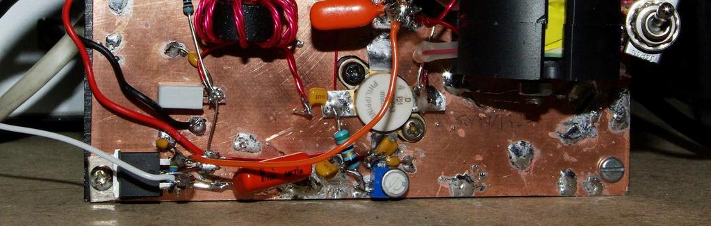
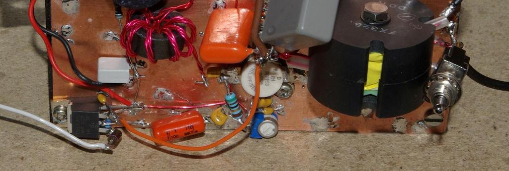
1 Medium Power 137kHz Linear Power Amplifier G4JNT Sept 2010 This project was conceived on the back of an envelope after running a WSPR beacon thorough my 600 Watt switch mode Power Amplifier, and setting light to the plastic shed containing the loading coil [1]. I realised I needed a lower power transmitter that would be safe to leave for continuous unattended operation. Previous tests on air had shown that a QRP Tx supplying around 6 watts was inadequate no one heard me and the big one was, well, too dangerous to feel comfortable about running unattended. So a 137kHz PA in the region of Watts was going to be needed. Initially I thought of building a class E design, and while looking for suitable devices for that, realised I had quite a large stock of a rather old, indifferent RF FETs salvaged from a scrap industrial plasma welder. These were RFPP53 devices, no data could be found but it was clear they were 50 volt devices, used eight to a board at 13.56MHz for 1kW output. They would make a quite nice linear transmitter for LF, and a linear design would be useful to have on the shelf for any future data-mode tests for waveforms with an varying amplitude component. Not too many linear designs for 137kHz exist, G0MRF has a design for a 250 Watt linear PA [2] Overall Design I wanted to run from a Volt supply so the devices would not be ideal, but so what I had plenty! It might be possible to get the Watts from a single device but the harmonics would be awful and efficiency poor, so a traditional push-pull design was the obvious route. Design for more power than is needed to start with; with a 28V supply, 60 Watts output requires a push-pull load resistance (between the drains) of 24 2 /60 * 2 = 19Ω. My LF system on 137kHz has 100Ω load resistance so a transformer of around 1:2 to 1:3 impedance transformation would do the job. Figure 1 Shows the circuit diagram of the final amplifier, and two photographs of the finished breadboard construction can be seen at the end. Output Transformer Looking through the junk box revealed several cores obtained over the years for SMPSU use. A 35mm diameter pot core made from 3C85 material was found which I knew this was good for SMPSUs; it had been in a homebrew one many years ago supplying 80 Watts or so. The all important core cross sectional area (A) was measured as 180mm 2 and using the low value of B max of 0.08 Tesla as a limit to avoid losses, the minimum number of volts per turn determined from : V RMS = F. N. A. B MAX V/N = 4.44 * Hz * 180*10-6 * 0.08 = 8.6 Volts / turn maximum (RMS volts) With a 26V supply, Vpk-pk across the two FET drains would be 52V, or 18V RMS, so a minimum of three turns is needed. Since the winding must be centre tapped, this has to become 4 primary turns. So for a 1:2 to 1:3 transformation 8 to 12 turns would be needed on the secondary. The bobbin could just be filled with 13 turns of single strand 0.8mm enamelled wire, so this was chosen as the maximum number to be used, with taps at 8 and 11 turns made by twisting the wire on itself at the appropriate position / turn, and passing the double-strand across the winding to the outside world for connection. This prevents any need for soldered joints inside the transformer bobbin. The toggle switch visible in the photographs selects either the 8 or 11 turn tap positions. The primary was wound on top of the secondary, and consisted of turns of bifilar twisted 1mm diameter wire. The whole lot just fitted
2 within the pot core, although it was a bit tight with all the tap positions all having to be brought to the outside world. Driver Stage The PA stage was built first, and to test it RF from a signal generator applied to the gates via a 1:1 RF transformer to see what sort of drive would be needed - no data sheet was available for the devices, everything had to be determined by measurement. To keep things simple, the gates are damped with 51Ω resistors, which also serve as the bias inject bias being set separately by individual presets for each device supplied from a stabilised 12V source. Differential impedance is therefore 100Ω, and with Miller feedback from drain to gate, we re probably looking at around a total R in of 50 to 100Ω at this low frequency. Each device was set to run with mA bias this seems to be a standard for high power MOSFETs. It turned out that the devices could be driven to saturation with 250mW from a 50 ohm source applied differentially to the gates. 150mW was sufficient for just-noticeable non-linearity in the output waveform. Also, and this was the good bit I couldn t get the things to go unstable. Probably due mainly to the low value of gate damping resistors, but also to the FETs being of ancient heritage and not terribly high frequency devices. At 200mW maximum, a BFY50 in class A is just asking to be used. Running from the 12V stabilised rail, a load resistance of 200 ohms will allow 360mW maximum with a quiescent current of 50mA. All comfortably within a BFY50 s ratings. So an intermediate transformer of 2:1 is now needed to transform this 200Ω optimum to the 50Ω or so of the device inputs. A small 15mm toroid, of 3C85 type material (recovered from the current sensing transformer of a defunct SMPSU) was wound with 8 quadrifilar turns. Two of the four strands were series connected for the primary with the remaining two paralleled for a thicker secondary, giving a 2:1 isolated transformer. I needed to obtain full power with less than +3dBm drive, so the driver had to have about 24dB gain (16 times voltage). With R load for the BFY50 of 200Ω an emitter degeneration resistor of about 200/16 = 12.5Ω was required. This was made up of a 20Ω unit setting the DC bias, and another 33Ω in parallel, decoupled at AC. Base bias resistors were chosen to give the 50mA quiescent, and present a load to the input of about 100 ohms. A 200 Ω preset used as an input attenuator gives an input close to 50Ω when set near to maximum. The IN4001 compensates bias with temperature. Control and Switching For beacon use the PA has to be capable of being enabled and disabled from a ground-to-tx line. A P- Channel Mosfet controls the input to the 12V regulator, so all bias and driver supplies are removed in standby, resulting in zero power consumption. A small 12V fan was also wired into circuit to allow a smaller heatsink to be used than might otherwise be reasonable remembering that for WSPR operation up to four minutes continuous transmission could occur. Results Maximum power output before device saturation set in was a bit lower than expected. 40 Watts could be obtained with ease from a 26V supply (using the 8 turn secondary tap into 50Ω for a device R load of 12.5Ω). But much above this the waveform began to flatten which is considerably below the 100 Watts that should be achieved at this load resistance. The devices saturated with about 3-4V across them, but as they were designed for 50V operation this perhaps may not be too unreasonable. So efficiency wouldn t be very
3 good, but the power out was at the level I was after, and it was very linear and stable, so call it 80 90% successful!. At 40W into a resistive load, the output sinewave looked perfect on a scope, and on a spectrum analyser showed to be in the -30dB region. Given the Q of the antenna system no Low Pass filter was going to be needed provided the amplifier wasn t driven into saturation. Connecting to the antenna (with the transformer tap adjusted for 100Ω load), again resulted in around 40 watts output. The unit has been running at this level continuously, with a WSPR duty cycle of 33% for a couple of days now. Replication You almost certainly won t get the RFPP53 devices I used, and I wouldn t recommend them anyway. Better to use proper 28V design devices with their lower R DSS(on) and lower saturation voltage drop. Audio devices like the 2SK414 will probably do they were more than adequate at 73kHz in the good old days and have a similar transconductance. They might not have as good a frequency response though. I have an inherent dislike of using switching type power MOSFETS for linear operation ; it just doesn t seem right, but others have done so successfully [2]. Setting the bias is a bit critical as they have a much higher transconductance, which results in potentially lots more gain and, lower input impedance. It will be worth trying devices from the IRF620 / 30/ 40 family which being rated at 200V gives plenty of safety margin. If gain proves too high, and instability sets in, connect a simple feedback resistor (with a DC blocking C) from Drain to Gate of each device. Start with 330 ohms and alter the value until you end up with a gain / stability that is acceptable. All the ferrite cores I used are a bit old-hat now as all my experimentation in SMPSUs was done in the last century - but the basic rule applies : V RMS = F. N. A. B MAX Any ferrites and cores designed for modern SMPSU use will work at 137kHz; almost certainly they will at 500kHz, and perhaps even on topband provided that equation is met. Beware core shapes though. Use UNGAPPED cores for transformers. Use gapped cores for inductors and for carrying DC but that s another story. If you have obscure ferrite cores that are clearly not part of SMPSUs, treat with caution. Those designed for EMC uses are appalling as transformer cores. Use an LC meter to check Al value, and if it is less than 1uH / turn 2 then the ferrite is probably not suitable for LF use. But with the plethora of SMPSU stuff in the catalogues, there is little point in trying to make use of dubious surplus cores of uncertain type Frequency Extension At 500kHz it was clear the output stage would still function perfectly, but the reduced FET input impedance at this frequency loaded the driver more, so it was not possible to actually get full power output as the driver went into saturation. It is quite possible, though, that with an uprated driver of something like 2 Watts capability and some resistive feedback around the output FETs to flatten the frequency response, broadband LF operation from 100kHz to 3.5MHz may be achievable. As I already have a perfectly good broadband PA for 500kHz to 40MHz I ll leave it for others to follow-up.
4 Figure 1 Circuit Diagram
![References [1]](/docs-images/79/80125548/images/5-0.jpg "http://www.g4jnt.")

5 References [1] and [2]
G6ALU 20W FET PA Construction Information
 G6ALU 20W FET PA Construction Information The requirement This amplifier was designed specifically to complement the Pic-A-Star transceiver developed by Peter Rhodes G3XJP. From the band pass filter an
Application Notes High Performance Audio Amplifiers
 High Performance Audio Amplifiers Exicon Lateral MOSFETs These audio devices are capable of very high standards of amplification, with low distortion and very fast slew rates. They are free from secondary
Single Conversion LF Upconverter Andy Talbot G4JNT Jan 2009
 Single Conversion LF Upconverter Andy Talbot G4JNT Jan 2009 Mark 2 Version Oct 2010, see Appendix, Page 8 This upconverter is designed to directly translate the output from a soundcard from a PC running
Trees, vegetation, buildings etc.
 EMC Measurements Test Site Locations Open Area (Field) Test Site Obstruction Free Trees, vegetation, buildings etc. Chamber or Screened Room Smaller Equipments Attenuate external fields (about 100dB) External
Some Thoughts on Electronic T/R Circuits
 Some Thoughts on Electronic T/R Circuits Wes Hayward, w7zoi, November 3, 2018 Abstract: Several schemes have been used to switch an antenna between a receiver and transmitter. A popular scheme with low
Third-Method Narrowband Direct Upconverter for the LF / MF Bands
 Third-Method Narrowband Direct Upconverter for the LF / MF Bands Introduction Andy Talbot G4JNT February 2016 Previous designs for upconverters from audio generated from a soundcard to RF have been published
1 TRANSISTOR CIRCUITS
 FM TRANSMITTERS The first group of circuits we will discuss are FM TRANSMITTERS. They can be called SPY TRANSMITTERS, FM BUGS, or a number of other interesting names. They all do the same thing. They transmit
The B7 Discrete Operational Amplifier Author: Tamas G. Kohalmi 7/5/2004
 The B7 Discrete Operational Amplifier Author: Tamas G. Kohalmi 7/5/2004 Table of Contents Part 1... pages 2-4 Part 2 pages 5-7 Part 1. This document describes a simple discrete operational amplifier that
Construction Manual 4m-Linear-Transverter XV4-15
 Construction Manual 4m-Linear-Transverter XV4-15 Holger Eckardt DF2FQ Kirchstockacherstr. 33 D-85662 Hohenbrunn 3207 Technical data exciter frequency: 21.0... 21.5 MHz RF frequency: 70.0.. 70.5 MHz supply
Feed Forward Linearization of Power Amplifiers
 EE318 Electronic Design Lab Report, EE Dept, IIT Bombay, April 2007 Feed Forward Linearization of Power Amplifiers Group-D16 Nachiket Gajare ( 04d07015) < nachiketg@ee.iitb.ac.in> Aditi Dhar ( 04d07030)
A GOOD REGENERATIVE RECEIVER WITH SIMPLE FINE TUNING (2008)
") A GOOD REGENERATIVE RECEIVER WITH SIMPLE FINE TUNING (2008) A good SSB-CW-AM regenerative receiver with a fine tuning by moving the wooden stick with a grounded piece of PCB towards the coil. A good regenerative
A GOOD REGENERATIVE RECEIVER WITH SIMPLE FINE TUNING (2008) A good SSB-CW-AM regenerative receiver with a fine tuning by moving the wooden stick with a grounded piece of PCB towards the coil. A good regenerative
PA FAN PLATE ASSEMBLY 188D6127G1 SYMBOL PART NO. DESCRIPTION. 4 SBS /10 Spring nut. 5 19A702339P510 Screw, thread forming, flat head.
 MAINTENANCE MANUAL 851-870 MHz, 110 WATT POWER AMPLIFIER 19D902797G5 TABLE OF CONTENTS Page DESCRIPTION.............................................. Front Page SPECIFICATIONS.................................................
Chapter 16 ANCIENT MODULATION And other topics
 1. Chapter 16, Harris CRYSTAL SETS TO SIDEBAND Frank W. Harris 2003 Chapter 16 ANCIENT MODULATION And other topics When I got back into ham radio 5 years ago, my ham friends told me that AM was extinct.
A 3 Watt LDMOS Driver for the 432MHz band
 A 3 Watt LDMOS Driver for the 432MHz band John C Worsnop. PhD CEng MIET, G4BAO Introduction The popularity of my 2.5-Watt driver kit for the 1296MHz band (1) and the recent publication of G4DDK s Iceni
HF LNA Doug Ronald W6DSR HF LNA
 HF LNA 1 High Dynamic Range 1.5 30 MHz Low Noise Amplifier. By Doug Ronald, W6DSR I have always had an interest in building high-performance receivers and transmitters for HF. An expected performance metric
Modifying the Qualcomm 1W Ku-Band PA for use on 3.4, 5.7 or 10.3 GHz
 Web Version 10-9-2001 Modifying the Qualcomm 1W Ku-Band PA for use on 3.4, 5.7 or 10.3 GHz K-Banke- 07/13/01 Hundreds of Ku-Band Qualcomm 1 watt power amplifiers have been modified and found their way
ZN414Z, ZN415E, ZN416E AM RADIO RECEIVERS
 GEC PLESSEY [SEMICONDUCTORS ZN414Z, ZN415E, ZN416E AM RADIO RECEIVERS FEATURES Single cell operation (1.1 to 1.6 volt, operating range) Low current consumption 150kHz to 3MHz frequency range (i.e. full
Construction Manual 6m-Linear-Transverter XV6/10
 Construction Manual 6m-Linear-Transverter XV6/10 Holger Eckardt DF2FQ Kirchstockacherstr. 33 D-85662 Hohenbrunn 2606 Technical data exciter frequency: 28... 30 MHz RF frequency: 50... 52 MHz supply voltage:
SPECIFICATIONS: Subcarrier Frequency 5.5MHz adjustable, FM Modulated +/- 50KHz. 2nd 11MHz >40dB down from 5.5MHz
 Mini-kits AUDIO / SUBCARRIER KIT EME75 Version4 SPECIFICATIONS: Subcarrier Frequency 5.5MHz adjustable, FM Modulated +/- 50KHz Subcarrier Output 1.5v p-p Output @ 5.5MHz DESCRIPTION & FEATURES: The Notes
Driver Amplifier for 7 Tesla MRI Smart Power Amplifier
 Driver Amplifier for 7 Tesla MRI Smart Power Amplifier presented by Kevin Kolpatzeck supervised by Prof. Dr.-Ing. Klaus Solbach Institute of Microwave and RF Technology University of Duisburg Essen Contents
The Crashcup 1V40 1W Transmitter
 The Crashcup 1V40 1W Transmitter by Chris Trask / N7ZWY Sonoran Radio Research P.O. Box 25240 Tempe, AZ 85285-5240 Email: christrask@earthlink.net 7 January 2009 Trask, Crashcup 1V40 1 7 January 2009 Introduction
Quadrature Upconverter for Optical Comms subcarrier generation
 Quadrature Upconverter for Optical Comms subcarrier generation Andy Talbot G4JNT 2011-07-27 Basic Design Overview This source is designed for upconverting a baseband I/Q source such as from SDR transmitter
Iron Powder Core Selection For RF Power Applications. Jim Cox Micrometals, Inc. Anaheim, CA
 HOME APPLICATION NOTES Iron Powder Core Selection For RF Power Applications Jim Cox Micrometals, Inc. Anaheim, CA Purpose: The purpose of this article is to present new information that will allow the
HF PA kit with built-in standalone raised cosine controller
 AN005 HF PA kit with built-in standalone raised cosine controller 1. Introduction The standard QRP Labs HF PA kit has an 8-bit shift register (74HC595) whose outputs control an 8- bit Digital-to-Analogue
QRPme.com Kits. Tx/Tuna Topper. Assembly and Operation Guide. Kits for the QRP and Electronics Hobbyist. Heatsink left off for better assembly viewing
 QRPme.com Kits Kits for the QRP and Electronics Hobbyist Tx/Tuna Topper Heatsink left off for better assembly viewing QRMme.com Kits Tx/Tuna Topper Contents Figures and Illustrations...............................
Bitx Version 3 Linear Amplifier Assembly
 Bitx Version 3 Linear Amplifier Assembly The power supply section has 2 options. 1 - AC input and a higher voltage on the IRF510 and +12 volts to the bitx. 2 - +12 volts applied to both the final and the
Stand Alone RF Power Capabilities Of The DEIC420 MOSFET Driver IC at 3.6, 7, 10, and 14 MHZ.
 Abstract Stand Alone RF Power Capabilities Of The DEIC4 MOSFET Driver IC at 3.6, 7,, and 4 MHZ. Matthew W. Vania, Directed Energy, Inc. The DEIC4 MOSFET driver IC is evaluated as a stand alone RF source
The Design of A 125W L-Band GaN Power Amplifier
 Sheet Code RFi0613 White Paper The Design of A 125W L-Band GaN Power Amplifier This paper describes the design and evaluation of a single stage 125W L-Band GaN Power Amplifier using a low-cost packaged
1 kw(dc) TWT Power Supply design.
 TWT Power Supply design.") 1 kw(dc) TWT Power Supply design. Luis Cupido Abstract Surplus TWTs, available on the amateur markets, seem to appear in much greater number than their power supplies. Also some of the power supplies are
1 kw(dc) TWT Power Supply design. Luis Cupido Abstract Surplus TWTs, available on the amateur markets, seem to appear in much greater number than their power supplies. Also some of the power supplies are
2-Tone Generator For 145Mhz
 Wolfgang Schneider, DJ8ES 2-Tone Generator For 145Mhz An RF amplifier stage is not only classified by amplification, which is as high as possible, and thus by its maximum output. What is frequently not
Hendricks QRP Kits BITX20A to BITX17A Conversion Instructions
 Hendricks QRP Kits BITX20A to BITX17A Conversion Instructions 30 November 2008 Converting your BITX20A Kit to a BITX17A Kit is not all that complex. It only requires that you change crystals and some resonance
The ROSE 80 CW Transceiver (Part 1 of 3)
") Build a 5 watt, 80 meter QRP CW Transceiver!!! Page 1 of 10 The ROSE 80 CW Transceiver (Part 1 of 3) Build a 5 watt, 80 meter QRP CW Transceiver!!! (Designed by N1HFX) A great deal of interest has been
Build a 5 watt, 80 meter QRP CW Transceiver!!! Page 1 of 10 The ROSE 80 CW Transceiver (Part 1 of 3) Build a 5 watt, 80 meter QRP CW Transceiver!!! (Designed by N1HFX) A great deal of interest has been
The Reliable Source... FERROPERM. Inductors. Transformers
 The Reliable Source... FERROPERM for High Quality Inductors and Transformers INDUCTORS AND TRANSFORMERS from FERROPERM UK Ltd. FERROPERM offers a manufacturing capability for the production of most types
Analyzing the Dynaco Stereo 120 Power Amplifier
 Analyzing the Dynaco Stereo 120 Power Amplifier The Stereo 120 Power Amplifier came out around 1966. It was the first powerful (60 watts per channel) solid state amplifier in wide production. Each channel
Many applications. Mismatched Load Characterization for High-Power RF Amplifiers PA CHARACTERIZATION. This article discusses the
 From April 2004 High Frequency Electronics Copyright 2004 Summit Technical Media, LLC Mismatched Load Characterization for High-Power RF Amplifiers By Richard W. Brounley, P.E. Brounley Engineering Many
Switching Boost Converter Power Supply
 Switching Boost Converter Power Supply Building switchmode converters is something I had basically no experience with and only a very casual theoretical understanding of. Some might say it would have been
One I had narrowed the options down, I installed some wire and started testing.
 Loft & Attic antennas for restricted spaces - M. Ehrenfried G8JNJ I ve recently been looking at designs for an efficient antenna that would fit in a loft. I hoped to find something that would work on with
: Hacking Bitx Version3B, C: : 20mt to 40mt band: PART I
 : Hacking Bitx Version3B, C: : 20mt to 40mt band: PART I Fig 1: Bitx Ver3C SBL-1 20 Conversion for Bitx40 The picture in Fig1 is a Bitx3C SBL-1 for 40mt band, constructed from the Bitx Version 3C SBL-1
A Prototype Frequency Machine for Plasma Tube Research
 A Prototype Frequency Machine for Plasma Tube Research This document describes a prototype Frequency Machine which I have built for the purposes of Rife experimentation and other plasma tube research.
Lecture 4 ECEN 4517/5517
 Lecture 4 ECEN 4517/5517 Experiment 3 weeks 2 and 3: interleaved flyback and feedback loop Battery 12 VDC HVDC: 120-200 VDC DC-DC converter Isolated flyback DC-AC inverter H-bridge v ac AC load 120 Vrms
Understanding Power Splitters
 Understanding Power Splitters How they work, what parameters are critical, and how to select the best value for your application. Basically, a 0 splitter is a passive device which accepts an input signal
JFET 101, a Tutorial Look at the Junction Field Effect Transistor 8May 2007, edit 2April2016, Wes Hayward, w7zoi
 JFET 101, a Tutorial Look at the Junction Field Effect Transistor 8May 2007, edit 2April2016, Wes Hayward, w7zoi FETs are popular among experimenters, but they are not as universally understood as the
Electrical Engineer. Lab2. Dr. Lars Hansen
 Electrical Engineer Lab2 Dr. Lars Hansen David Sanchez University of Texas at San Antonio May 5 th, 2009 Table of Contents Abstract... 3 1.0 Introduction and Product Description... 3 1.1 Problem Specifications...
Building a Bitx20 Version 3
 Building a Bitx20 Version 3 The board can be broken into sections and then built and tested one section at a time. This will make troubleshooting easier as any problems will be confined to one small section.
ssb transceiver single-band using the LM373 communications IC
 single-band ssb transceiver using the LM373 communications IC How to use the versatile LM373 and several other ICs to build a compact ssb transceiver for 14 MHz About two years ago a new products announcement
ICOM IC-201 Allmode Transceiver
 ICOM IC-201 Allmode Transceiver Alignment Procedure Please note: This procedure is reengineered by myself and may be not in accordance with the original procedure from the manufacturer! So I can t accept
RF and Optical Bolometer
 RF and Optical Bolometer When RF energy is delivered to a resistive load it dissipates heat. If the load has a relatively poor thermal coupling to its surrounding environment its temperature will rise.
DISCRETE DIFFERENTIAL AMPLIFIER
 DISCRETE DIFFERENTIAL AMPLIFIER This differential amplifier was specially designed for use in my VK-1 audio oscillator and VK-2 distortion meter where the requirements of ultra-low distortion and ultra-low
Shielded Power Inductors
 Shielded Power Inductors MN509 Shielded inductor with minimum EMI Minimum power loss Non standard values available Low DC resistance Flat top for SMT operations Specifications Inductance tested at 100KHz
Bel Canto Design evo Digital Power Processing Amplifier
 Bel Canto Design evo Digital Power Processing Amplifier Introduction Analog audio power amplifiers rely on balancing the inherent linearity of a device or circuit architecture with factors related to efficiency,
Switch Mode Power Supplies and their Magnetics
 Switch Mode Power Supplies and their Magnetics Many factors must be considered by designers when choosing the magnetic components required in today s electronic power supplies In today s day and age the
and succeed without going MAD!!! 2017
 and succeed without going MAD!!! 2017 Good points of the design and kit? Nice, compact 45W HF-AMP (as claimed) Drive power requirements of 100mW for 45W out Uses MOS-FET (IRF-530) transistors as finals
11. Audio Amp. LM386 Low Power Amplifier:
 EECE208 INTRO TO EE LAB Dr. Charles Kim 11. Audio Amp Objectives: The main purpose of this laboratory exercise is to design an audio amplifier based on the LM386 Low Voltage Audio Power Amplifier chip
VHF LAND MOBILE SERVICE
 RFS21 December 1991 (Issue 1) SPECIFICATION FOR RADIO APPARATUS: VHF LAND MOBILE SERVICE USING AMPLITUDE MODULATION WITH 12.5 khz CARRIER FREQUENCY SEPARATION Communications Division Ministry of Commerce
Burning Amp 2. by Nelson Pass. Introduction. Concept
 Burning Amp 2 by Nelson Pass Introduction In Burning Amp 1 we examined an amplifier circuit designed to complement the hardware we gave away to some attendees at last October's Burning Amp Festival in
($E.. DISCLAIMER. b C
 ? DISCLAIMER ($E.. This report was prepared as an accouht of work sponsored by an agency of the United States Government. Neither the United States Government nor any agency thereof, nor any of their employees,
Operational Amplifiers
 Operational Amplifiers Table of contents 1. Design 1.1. The Differential Amplifier 1.2. Level Shifter 1.3. Power Amplifier 2. Characteristics 3. The Opamp without NFB 4. Linear Amplifiers 4.1. The Non-Inverting
UNIT 2. Q.1) Describe the functioning of standard signal generator. Ans. Electronic Measurements & Instrumentation
 Describe the functioning of standard signal generator. Ans. Electronic Measurements & Instrumentation") UNIT 2 Q.1) Describe the functioning of standard signal generator Ans. STANDARD SIGNAL GENERATOR A standard signal generator produces known and controllable voltages. It is used as power source for the
UNIT 2 Q.1) Describe the functioning of standard signal generator Ans. STANDARD SIGNAL GENERATOR A standard signal generator produces known and controllable voltages. It is used as power source for the
Filters And Waveform Shaping
 Physics 3330 Experiment #3 Fall 2001 Purpose Filters And Waveform Shaping The aim of this experiment is to study the frequency filtering properties of passive (R, C, and L) circuits for sine waves, and
WA3RNC 30 METER CRYSTALPLEXER TRANSMITTER KIT ASSEMBLY INSTRUCTIONS
 WA3RNC 30 METER CRYSTALPLEXER TRANSMITTER KIT ASSEMBLY INSTRUCTIONS Description The WA3RNC 30 Meter Crystalplexer is a low power crystal controlled QRP transmitter offering a significantly improved tuning
High Voltage Supply. 330 V from 12 V. For the Valved RIAA Preamplifier and other applications POWERSUPPLY
 For the Valved RIAA Preamplifier and other applications High Voltage Supply 33 V from 12 V Design by T. Giesberts Although this supply was primarily designed for use with the Valved RIAA Preamplifier,
Exercise 2: AC Voltage and Power Gains
 Exercise 2: AC Voltage and Power Gains an oscilloscope. Signals of equal magnitude but opposite polarity are needed for each transistor (Q1 and Q2). Center-tapped input transformer T1 is used as a phase
Evaluation of competitor-produced equivalents of Micrometals powdered iron toroidal cores
 Evaluation of competitor-produced equivalents of Micrometals powdered iron toroidal cores Hans Summers, January 2014 American-made Micrometals toroids are difficult to obtain and expensive to ship internationally.
QRPme.com Kits. Tx/Tuna Topper. Assembly and Operation Guide. Kits for the QRP and Electronics Hobbyist. Heatsink left off for better assembly viewing
 QRPme.com Kits Kits for the QRP and Electronics Hobbyist Tx/Tuna Topper Heatsink left off for better assembly viewing Contents Figures and Illustrations............................... 3 Jumpers............................................
EE12: Laboratory Project (Part-2) AM Transmitter
 AM Transmitter") EE12: Laboratory Project (Part-2) AM Transmitter ECE Department, Tufts University Spring 2008 1 Objective This laboratory exercise is the second part of the EE12 project of building an AM transmitter in
EE12: Laboratory Project (Part-2) AM Transmitter ECE Department, Tufts University Spring 2008 1 Objective This laboratory exercise is the second part of the EE12 project of building an AM transmitter in
Nonlinear Macromodeling of Amplifiers and Applications to Filter Design.
 ECEN 622(ESS) Nonlinear Macromodeling of Amplifiers and Applications to Filter Design. By Edgar Sanchez-Sinencio Thanks to Heng Zhang for part of the material OP AMP MACROMODELS Systems containing a significant
KN-Q10 Assembly Manual
 KN-Q10 Assembly Manual Translated by Adam Rong, BD6CR/4 with permission from Ke Shi, BA6BF Edited by Stephen, VK2RH Revision B, Oct 14, 2010 Thank you for purchasing the KN-Q10 4 Band SSB/CW Dual Mode
Developing a 1296 MHz Beacon. By Kevin Murphy ZL1UJG April 2009
 Developing a 1296 MHz Beacon By Kevin Murphy ZL1UJG April 2009 1 Stage Functions Oscillator Module Multiplier Module Amplifier Module Keyer PSU Module Circulator/Filter 2 A good start for an oscillator
Lecture 19 - Single-phase square-wave inverter
 Lecture 19 - Single-phase square-wave inverter 1. Introduction Inverter circuits supply AC voltage or current to a load from a DC supply. A DC source, often obtained from an AC-DC rectifier, is converted
Designing Your Own Amplifier, Part 1: Voltage Amplifier Stages
 Audio Classroom Designing Your Own Amplifier, Part 1: Voltage Amplifier Stages This article appeared originally in Audiocraft, March 1956. 1956 by Audiocom, Inc. BY NORMAN H. CROWHURST How, do you go about
Maintenance Manual LBI-38531G MHz, 110 WATT POWER AMPLIFIER 19D902797G1 DESCRIPTION TABLE OF CONTENTS
 Maintenance Manual LBI-38531G 136-174 MHz, 110 WATT POWER AMPLIFIER 19D902797G1 TABLE OF CONTENTS Page DESCRIPTION.............................................. Front Cover SPECIFICATIONS.................................................
3 Circuit Theory. 3.2 Balanced Gain Stage (BGS) Input to the amplifier is balanced. The shield is isolated
 Input to the amplifier is balanced. The shield is isolated") Rev. D CE Series Power Amplifier Service Manual 3 Circuit Theory 3.0 Overview This section of the manual explains the general operation of the CE power amplifier. Topics covered include Front End Operation,
Rev. D CE Series Power Amplifier Service Manual 3 Circuit Theory 3.0 Overview This section of the manual explains the general operation of the CE power amplifier. Topics covered include Front End Operation,
Model 25A Manual. Introduction:
 Model 25A Manual Introduction: The Model 25A drive electronics is a high voltage push-pull linear power amplifier capable of output voltage swings in the order of 145v P-P, push-pull. The Model 25A provides
A 16Ω Audio Amplifier with 93.8 mw Peak loadpower and 1.43 quiscent power consumption
 A 16Ω Audio Amplifier with 93.8 mw Peak loadpower and 1.43 quiscent power consumption IEEE Transactions on circuits and systems- Vol 59 No:3 March 2012 Abstract A class AB audio amplifier is used to drive
ANALOG FUNDAMENTALS C. Topic 4 BASIC FET AMPLIFIER CONFIGURATIONS
 AV18-AFC ANALOG FUNDAMENTALS C Topic 4 BASIC FET AMPLIFIER CONFIGURATIONS 1 ANALOG FUNDAMENTALS C AV18-AFC Overview This topic identifies the basic FET amplifier configurations and their principles of
55:041 Electronic Circuits The University of Iowa Fall Exam 3. Question 1 Unless stated otherwise, each question below is 1 point.
 Exam 3 Name: Score /65 Question 1 Unless stated otherwise, each question below is 1 point. 1. An engineer designs a class-ab amplifier to deliver 2 W (sinusoidal) signal power to an resistive load. Ignoring
i. At the start-up of oscillation there is an excess negative resistance (-R)
") OSCILLATORS Andrew Dearn * Introduction The designers of monolithic or integrated oscillators usually have the available process dictated to them by overall system requirements such as frequency of operation
OSCILLATORS Andrew Dearn * Introduction The designers of monolithic or integrated oscillators usually have the available process dictated to them by overall system requirements such as frequency of operation
Basic Harris DX Transmitter Tutorial
 BASIC DX TUTORIAL Basic Harris DX Transmitter Tutorial Basic DX Theory The Harris DX Transmitters series, introduced in 1986, have proven to be the most efficient method of Amplitude Modulation at medium
10W HF Linear PA. A low-cost, high-performance HF Linear PA covering 2-30MHz. 10W HF Linear Power Amplifier kit assembly manual
 10W HF Linear PA 10W HF Linear Power Amplifier kit assembly manual A low-cost, high-performance HF Linear PA covering 2-30MHz Designed and produced by QRP Labs, 2018 10W HF Linear PA kit assembly 1.01
Mosfet amplifier gain
 Mosfet amplifier gain This structure with p-type body is the basis of the n- type MOSFET, which requires the addition of n-type source and drain regions. For an enhancement-mode, n-channel MOSFET, the
The Micromega MyAMP. A serious design challenge
 The Micromega MyAMP A serious design challenge Following the successful launch of the MyDAC, MyZIC and MyGROOV, the Micromega engineers had a serious design challenge: to complete the MY range by adding
HF Power Amplifier (Reference Design Guide) RFID Systems / ASP
 RFID Systems / ASP") 16 September 2008 Rev A HF Power Amplifier (Reference Design Guide) RFID Systems / ASP 1.) Scope Shown herein is a HF power amplifier design with performance plots. As every application is different and
16 September 2008 Rev A HF Power Amplifier (Reference Design Guide) RFID Systems / ASP 1.) Scope Shown herein is a HF power amplifier design with performance plots. As every application is different and
Power Amplifiers. Class A Amplifier
 Power Amplifiers The Power amplifiers amplify the power level of the signal. This amplification is done in the last stage in audio applications. The applications related to radio frequencies employ radio
HARRIS 222 AMPLIFIER. Details and Modifications Ron Marosko, K5LLL
 HARRIS 222 AMPLIFIER Details and Modifications Ron Marosko, K5LLL HARRIS CH 11 Amp The Harris Channel 11 amplifier is a brother to the one used by many on 6M. It is capable of 1 KW output and uses a nominal
Application Note MHz, Class D Push-Pull, 1.7KW RF Generator with Microsemi DRF1300 Power MOSFET Hybrid
 13.56 MHz, Class D Push-Pull, 1.7KW RF Generator with Microsemi DRF1300 Power MOSFET Hybrid June 26, 2008 By Gui Choi Sr. RF Application Engineer The DRF1300/CLASS-D Reference design is available to expedite
MAINTENANCE MANUAL TRANSMITTER/RECEIVER BOARD CMN-234A/B FOR MLSU141 & MLSU241 UHF MOBILE RADIO TABLE OF CONTENTS
 MAINTENANCE MANUAL TRANSMITTER/RECEIVER BOARD CMN-234A/B FOR MLSU141 & MLSU241 UHF MOBILE RADIO TABLE OF CONTENTS DESCRIPTION... 2 CIRCUIT ANALYSIS... 2 TRANSMITTER... 2 9-Voft Regulator... 2 Exciter...
El-Cheapo - A Really Simple Power Amplifier
 El-Cheapo - A Really Simple Power Amplifier Rod Elliott - ESP (Semi-Original Design) "Semi-Original Design" - What is that supposed to mean? Well, many years ago, there was an amplifier circuit in a magazine
SGM6130 3A, 28.5V, 385kHz Step-Down Converter
 GENERAL DESCRIPTION The SGM6130 is a current-mode step-down regulator with an internal power MOSFET. This device achieves 3A continuous output current over a wide input supply range from 4.5 to 28.5 with
Testing and Verification Waveforms of a Small DRSSTC. Part 1. Steven Ward. 6/24/2009
 Testing and Verification Waveforms of a Small DRSSTC Part 1 Steven Ward www.stevehv.4hv.org 6/24/2009 Power electronics, unlike other areas of electronics, can be extremely critical of small details, since
R. W. Erickson. Department of Electrical, Computer, and Energy Engineering University of Colorado, Boulder
 R. W. Erickson Department of Electrical, Computer, and Energy Engineering University of Colorado, Boulder 6.3.5. Boost-derived isolated converters A wide variety of boost-derived isolated dc-dc converters
PROJECT ON MIXED SIGNAL VLSI
 PROJECT ON MXED SGNAL VLS Submitted by Vipul Patel TOPC: A GLBERT CELL MXER N CMOS AND BJT TECHNOLOGY 1 A Gilbert Cell Mixer in CMOS and BJT technology Vipul Patel Abstract This paper describes a doubly
Code: 9A Answer any FIVE questions All questions carry equal marks *****
 II B. Tech II Semester (R09) Regular & Supplementary Examinations, April/May 2012 ELECTRONIC CIRCUIT ANALYSIS (Common to EIE, E. Con. E & ECE) Time: 3 hours Max Marks: 70 Answer any FIVE questions All
Wimborne Publishing, reproduce for personal use only
 In part 1 we looked at some of the principles involved with measuring magnetic fields. This time, we take a more practical approach and look at some experimental circuits. The circuits illustrated are
AN102. JFET Biasing Techniques. Introduction. Three Basic Circuits. Constant-Voltage Bias
 AN12 JFET Biasing Techniques Introduction Engineers who are not familiar with proper biasing methods often design FET amplifiers that are unnecessarily sensitive to device characteristics. One way to obtain
EE 332 Design Project
 EE 332 Design Project Variable Gain Audio Amplifier TA: Pohan Yang Students in the team: George Jenkins Mohamed Logman Dale Jackson Ben Alsin Instructor s Comments: Lab Grade: Introduction The goal of
Transmission Line Signal Sampling By Don Steinbach, AE6PM
 Transmission Line Signal Sampling By Don Steinbach, AE6PM When I was finalizing the mechanical layout of my remotely-operated 3-position coaxial antenna switch (Fig. 1), I wanted to include a way to bring
HT-1A Dual Band CW QRP Transceiver. Kit Building Instructions
 HT-A Dual Band CW QRP Transceiver Kit Building Instructions Rev B, July 8, 08 Designed by BD4RG Exclusively distributed by CRKITS.COM and its worldwide distributors Join the group http://groups.io/g/crkits
14 MHz Single Side Band Receiver
 EPFL - LEG Laboratoires à options 8 ème semestre MHz Single Side Band Receiver. Objectives. The objective of this work is to calculate and adjust the key elements of an Upper Side Band Receiver in the
Fun with Preamps A great way to pass a cold winter afternoon is to homebrew some preamps Designs and Benchmarks Construction The W7IUV Preamp
 Fun with Preamps A great way to pass a cold winter afternoon is to homebrew some preamps Built two preamps today. I ve been thinking of building a couple as a general interest project and today turned
Miniproject: AM Radio
 Objective UNIVERSITY OF CALIFORNIA AT BERKELEY College of Engineering Department of Electrical Engineering and Computer Sciences EE05 Lab Experiments Miniproject: AM Radio Until now, the labs have focused