Aperture synthesis radar imaging in coherent scatter radars: Lesson from Jicamarca
|
|
|
- Matthew Grant
- 6 years ago
- Views:
Transcription

1 Aperture synthesis radar imaging in coherent scatter radars: Lesson from Jicamarca J. L. Chau1, D. L. Hysell2, and M. Urco1 1Radio Observatorio Jicamarca, Instituto Geofísico del Perú, Lima 2Earth and Atmospheric Sciences, Cornell University, Itahca, NY, USA EISCAT Radar School, Sodankyla, Finland, August 29, 2012
 Irregularity comparison: insitu vs.")
2 Outline Introduction Equatorial Ionospheric Irregularities RTI Maps and Slit Camera Aperture synthesis for Ionospheric applications Methods Phase calibration Jicamarca Examples (EEJ, ESF, 150 km) Irregularity comparison: insitu vs. Radar Latest developments
3 What can we get from single beam radar measurements? If the scattering is volume-filling, i.e., the whole illuminated volume presents the same statistical characteristics (space and time), then the information is contained in the spectrum. For example, in incoherent scatter spectrum, the spectra shape determines the temperature of ions and electrons, and also composition. If the scattering is not volume filling (the case for most coherent echoes), then the single beam information provides a weighted average information inside the illuminated volume. Is it possible to get spatial information? Note: Coherent echoes are db stronger than typical ISR echoes.

4 Equatorial Ionospheric Irregularities [courtesy of J. Vierinen]
")
5 Equatorial Irregularities (2) Below 200 km
6 Range-Time Intensity (RTI) maps
 of such structures.")
7 Range-Time Intensity plots as Images : Slit camera interpretation Assuming spatial structures are frozen, drifting across the radar, the RTI maps could represent Images (altitude vs. zonal) of such structures. Horizontal Distance (km)


8 Slit-camera Analogy and Problems In some applications like races it is useful In many other applications it provides misleading results: Slow structures are stretch out Fast-moving structures are compressed. In general, it is difficult to discriminate space-time features. used with permission Tom Dahlin


9 Ionospheric Radar Imaging: Introduction The radar imaging techniques used in studying the ionosphere, are an extension of more general techniques used in getting images with non-visible wavelengths (radio frequency, infrared, ultrasound, etc.) and in particular of imaging techniques with radars. Among radar imaging techniques we have: SAR Imaging Planetary imaging Underground imaging (Georadar) Meteorological radar images Ionospheric images Radar imaging are part of more general techniques used in Astronomy.
10 Atmospheric/Ionospheric Target In atmospheric applications, besides the problems of discriminating space-time features of moving structures across the beam, radar have finite beam widths and irregularities can appear, grow, dissipate, disappear, inside the beam!
 The pin-hole camera Object")

11 Analogy with an Optical Camera (1) The pin-hole camera Object Aperture Image Far field Far field Optical wavelength ~ 500 nm
12 Analogy with an Optical Camera (2) Fourier Operations Object Plane B(θ ) True Brightness ~meters ~kms Fourier B( θ ) V ( r) Aperture Plane ˆB(θ) V (r) True Visibility = A 2 (θ) B(θ) Measured Visibility Vˆ ( r ) Image Plane ~meters ~kms ˆ Fourier B( θ ) Vˆ( r) B ˆ ( θ ) Estimated Brightness [from Woodman, 1997] In radio astronomy: Camera without flash In radar imaging: Camera with flash
13 Aperture Synthesis Radar Problem Given: ˆV = a a M B find ˆB that best agrees with B. where a can be an arbitrary complex vector, e.g., Truncation (like windowing in spectral analysis) Gaps Focusing (needed for near-field applications)
14 Aperture Synthesis Radar Imaging Algorithms Beamforming or Non-parametric Methods. These methods do not make any assumption on the covariance structure of the data. Fourier-based Capon or Linear Constraint Minimum variance beam forming Parametric methods. These methods usually make use of a known functional form B, error covariances, or other a priori information. Maximum Entropy Model fitting. For example, a Brightness modeled by N anisotropic Gaussian blobs Single value decomposition (SVD)+MUltiple SIgnal Classification (MUSIC) (developed for the localization of discrete scatterers) Other CLEAN, RELAX (Super CLEAN) (from Radio Astronomy) APES, variants of Capon, etc. (from high resolution spectral analysis)
15 Ionospheric Radar Imaging: Peculiarities of the target Spatially 3D. Changes with time in two different time scales: short, that defines the color (frequency spectrum) long, non-stationary scale. It is non stationary and non homogeneous, representing a stochastic process of 4 dimensions. Normally, once has a small number of independent samples to average. Given these characteristics, how do we solve the problem? Shall we do a simple Fourier inversion? Are there any constraints or a priori information that we could consider? If so, how?
16 Fourier-based Methods Vˆ = a* a * MB Ideally B could be obtained by a simple Fourier inversion. If a only represents truncation, i.e., V is not zero outside the aperture, the estimation can be improved by using proper weighting functions (equivalent to windowing in spectral analysis). The use of weighting functions is also called as apodization. If a represents near field effects, e.g., for lower atmospheric applications, the image can be focused by correcting it with a known a. If a is more complicated, which is usually the case (e.g., representing gaps, truncation), clever approaches are needed to CLEAN/deconvolve dirty brightness images obtained from Fourier inverting.
17 Capon Method ˆ capon (, ) = wv + ˆ( ) w B θω ω Bˆ (, ) θω is a minimum w(θ ) is such that capon under the constrain w i ( θ )plane( θ, i) =1 Bˆ ( θω, ) = 1 ev ˆ ( ω ) e capon + 1 [ M' θ, i ] = w [ ] DFT θ,i It reduces to a matrix inversion!!!! It is an adaptive method that finds a suitable w, based on the data for each pointing angle.


18 Comparison of Aperture Synthesis Radar Imaging Techniques Very Easy to implement Very fast processing Poor resolution. Requires good SNR. Usually gets dirty images Fourier Transform Easy to implement Fast processing Adaptive pointing Requires good SNR Matrix inversion Hard to implement Slow processing Better estimates and Higher resolution. Takes into account statistical errors Set of non-linear equations
19 Maximum Entropy Method (MaxEnt) Model-based inversion process where B(θ,ω) is a positive definite function constrained to be consistent with the data ( V ˆ(r,ω) ) to a specified accuracy (based on self and statistical errors). λ j h j ˆB(θ,ω) e λ j h j (θ ) e λ j h j (θ ) dθ : Lagrange multiplier, one for each visibility measurement ( θ ) : point-spread function of the interferometer denominator: like the Gibbs canonical partition function By maximizing the Shannon Entropy ( S B j log B j ), including the constraints, one gets a well-posed set of N simultaneous nonlinear equations for N Lagrange multipliers. The estimation problem is reduced to solve numerically the set of non-linear equations (e.g., Powell method). It is a method that deconvolves via regularization.
20 MaxEnt: Improvements Use of a priori information, Transmitting beam pattern (avoids estimating the image in a region that is not illuminated) Different receiver beam patterns (allows the use of different receiver antenna sizes). Full-covariance matrix. Errors between Re and Im components and between baselines are no longer assumed to be uncorrelated. Data and model need to be diagonalized. [from Hysell and Chau,2006] Re and Im errors are correlated Amp and Phase errors are un correlated
21 Model Fitting In this technique one makes a parametric model of B and uses imaging equations to calculate the expected measurements. One then adjust the parameters of the model to get the best fit model. There are three steps involve in model fitting: (1) design a model defined by a number of adjustable parameters; (2) Choose a figure-of-merit function; (3) Adjust the parameters to minimize the merit function. The goals are to obtain: (1) Best-fit values for the parameters, (2) A measure of the goodness-of-fit of the optimized model (relative to the measurement errors); (3) Estimates of the uncertainty in the best-fit parameters. Model fitting has many desirable properties. It can take into account all the details of the measurement process (e.g., antenna patterns, calibration phases), which won t be a simple Fourier transform; and because it operates in the domain of observation (V), where the statistics of the measurement process are well understood (error covariances), it can estimate the statistical uncertainties of the parameters of the best-fit model, which may be the atmospheric/ionospheric important quantities. However, it also has serious problems: it may be difficult to choose a suitable parameterization model, the solutions are not unique, and it can be much, much slower than the conventional beamforming and deconvolution methods.
22 Uses an practical considerations of model fitting If the primary objective is the image, then model fitting is not useful, it is better to use conventional methods. However, model fitting is very useful for interpreting sparse or uncalibrated data, and for quantitative analysis. Model fitting could be used for the following: Checking and adjusting amplitude and/or phase calibration against known sources, e.g., modeling a Radio Star as a point-source. If the source is simple enough to be accurately represented by a parametric model, then model fitting provides accurate estimates of the model parameters. Estimates derive in this way directly from V will always be more reliable than parameters estimated from a deconvolved image. Model fitting can be used to improve the behavior of commonly used imaging techniques, e.g., CLEAN and Maxim Entropy. Hybrid methods. For example, one can get an image using conventional images, and improve the estimate using model fitting. The conventional image would serve to provide a very good initial guess and more importantly a good idea of the model to be used, e.g., number of Gaussian blobs. Common fitting problems: (1) Finding global minimum; (2) Slow convergence; (3) Constraints; (4) Choosing the right number of parameters or components.
23 Phase Calibration Procedures Use of common signal From natural sources. Radio Stars [e.g., Cygnus A, Hydra]. Equatorial electrojet Atmospheric signal after a long integration. Meteor head echoes From artificial sources Mobile beacons with a GPS system A common signal fed to receiving lines [e.g., Kudeki and Sürücü, 1991]. Optimizing the estimated image Maximize the entropy Minimize peaks 2 i π ( dx ) (1) 1/2 1/2 () (0) (, ) (, ) ij θ x + dy ij θ y + ia ij H t ij = A ijpi x y Pj x y e λ + A(2) ij + ia(3) ij ρ θ θ θ θ

24 How to display radar images (1)

25 How to display radar images (2)
26 How to display radar images (3) Green -200 to 200 m/s RGB - Millions of color image Red -600 to -200 m/s Blue 200 to 600 m/s

.")
27 The Jicamarca Radio Observatory Built in 1961 by the US NBS and then donated to IGP in Operating frequency: 50 MHz Antenna type: array of 18,432 dipoles, organized in 8x8 cross-polarized modules. Pointing directions: within 3 degrees from on-axis. Phase changes are currently done manually. Transmitters: 3 x 1.5 MW peak-power with 5% duty cycle. Located under the magnetic equator (dip 1o). Just 300m x 300m
.")
28 Examples of ESF Radar Imaging at Jicamarca Tx using two quarter antennas, phased to have a wide beam in the EW direction. 8 digital Rx channels for imaging. A pair of modules can be used for single baseline interferometry. Automated phase calibration procedure, using beacon on the hill (relative). Absolute calibration from Hydra, meteor-heads, colors (FFT points) ESF images are obtained every 2 seconds and 300 m. The angular resolution is ~ o
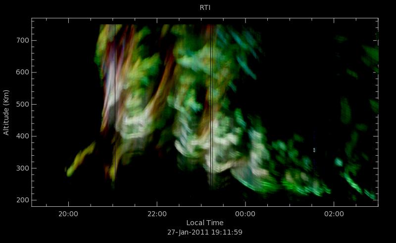
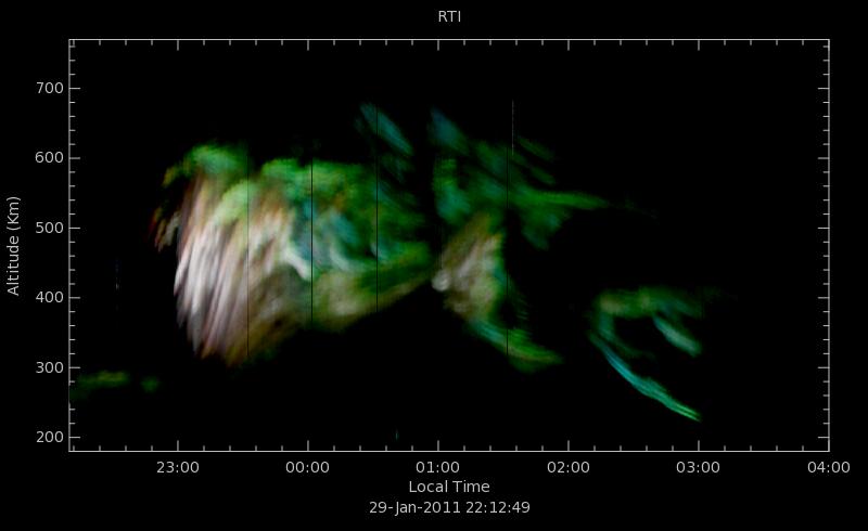
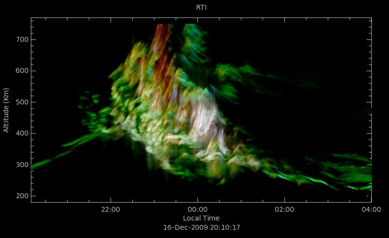
 plot using Doppler information (RTDI).")
29 ESF RTDI: Slit camera interpretation East (km) West Typical RTI maps are shown with false colors (colors from a pre-defined color table are associated to the signal intensity). Here we use Doppler for color. True 24-bit color range time intensity (RTI) plot using Doppler information (RTDI). RTI map is obtained for three Doppler regions centered around: -ve (Red), zero (Green), and +ve (Blue) Doppler velocities. It allows, for example, identification of regions and times where there is a depletion channel pinching off, Doppler aliasing, Doppler widening, etc.

30 Examples of ESF RTDI
31 ESF RTDI + Imaging (1)

32 Upper E region RTDI + Imaging
33 150-km RTDI + Imaging


34 Spectra cuts from Imaging results
. Using imaging, we can get the spectra for different synthesized beams and range resolutions.")

35 Multi-beam Radar Observations from Imaging JULIA-like parameters can be obtained from interferometry using a pair of antennas (SNR, mean vertical Doppler, zonal drift). Using imaging, we can get the spectra for different synthesized beams and range resolutions. In this example, each synthesized scattering volume is 0.2 o and 600m obtained every 10 sec. Investigate the possibility of estimating the irregularity spectrum by measuring the radar Doppler spectrum with different averaging volumes [e.g., Hysell and Chau, 2004]

36 Common volume: C/NOFS vs JRO

37 Irregularity comparison: In-situ vs. Radar PLP Density VEFI Drifts [from Hysell et al., 2009]

38 Latest developments Real time processing Optimized code (memory, loops, ) Use of Multithreads in an 8-core PC. 10sec, km, 1.5 km res., 16 FFT points, 8 rxs. Determination of blob vector motion - Particle Image Velocimetry (PIV)

39 Imaging + PIV
40 Summary Coherent scatter radars should have aperture synthesis radar capabilities to: Resolve space and time ambiguities Increase the angular resolution with small additional modules. Nowadays processing can be done in realtime, even when MaxEnt methods are used. Robust phase calibration procedures are needed particularly for real-time applications. In some applications, antenna compression techniques are good complement for aperture synthesis imaging.


41
42 Ionospheric Radar Imaging: General Considerations In atmospheric/ionospheric radar imaging, scattered signals are caused by refractive index fluctuations on the propagation path of transmitted radar pulses. At VHF and higher frequencies the scattered signal fraction is so minor that there is no need to consider secondary scattering of the scattered signals or the extinction of a propagating pulse due to scattered energy. From Radio Astronomy jargon, we called: Brightness, the angular distribution [B(Θ x,θ y )]of the target we are after (e.g., EEJ, ESF) multiplied by the transmitting and receiving antenna patterns. Visibility, the spatial autocorrelation function of the field at the aperture, due to the Brightness. It is a function of distance in x and y [V(r x,r y )]. From analogy with temporal-frequency spectral estimation: The largest separation between antennas, is equivalent to the observation time. Therefore it determines the angular resolution. The shortest separation between visibility samples, is equivalent to temporal sampling period, and determines the maximum unambiguous angular range that can be imaged ( Nyquist angle).

43 PIV Cross Correlation
Radars: Powerful tools to study the Upper Atmosphere
 Radars: Powerful tools to study the Upper Atmosphere Jorge L. Chau 1 and Roger H. Varney 2 1 Radio Observatorio de Jicamarca, Instituto Geofísico del Perú, Lima 2 Electrical and Computer Engineering, Cornell
Jicamarca Radio Observatory: 50 years of scientific and engineering achievements
 Jicamarca Radio Observatory: 50 years of scientific and engineering achievements Jorge L. Chau, David L. Hysell and Marco A. Milla Radio Observatorio de Jicamarca, Instituto Geofísico del Perú, Lima Outline
ISR Coordinated Science at Equatorial Latitudes
 ISR Coordinated Science at Equatorial Latitudes J. L. Chau 1, D. L. Hysell 2, and E. Kudeki 3 1 Radio Observatorio de Jicamarca, Instituto Geofísico del Perú, Lima 2 Earth and Atmospheric Sciences, Cornell
Radio Observatorio de Jicamarca - Instituto Geofísico del Perú
 JRO Operations INCOHERENT ECHOES Experiments summary EXPERIME NTS MEASURED PARAMETERS RANGE (km) RESOLUTION (HEIGHT TIME) ANTENNA TRANSMITTER S (POWER) Duty Cycle (%) HYBRID2 (Long Pulse-LP and Double
Antennas and Propagation. Chapter 5c: Array Signal Processing and Parametric Estimation Techniques
 Antennas and Propagation : Array Signal Processing and Parametric Estimation Techniques Introduction Time-domain Signal Processing Fourier spectral analysis Identify important frequency-content of signal
AGF-216. The Earth s Ionosphere & Radars on Svalbard
 AGF-216 The Earth s Ionosphere & Radars on Svalbard Katie Herlingshaw 07/02/2018 1 Overview Radar basics what, how, where, why? How do we use radars on Svalbard? What is EISCAT and what does it measure?
Incoherent Scatter Experiment Parameters
 Incoherent Scatter Experiment Parameters At a fundamental level, we must select Waveform type Inter-pulse period (IPP) or pulse repetition frequency (PRF) Our choices will be dictated by the desired measurement
Radar interferometric imaging for the EISCAT Svalbard Radar
 Radar interferometric imaging for the EISCAT Svalbard Radar Tom Grydeland 1,2 Jorge L. Chau 3 César La Hoz 1 1 Department of Physics, University of Tromsø 2 Currently at the University Centre on Svalbard
Antennas and Propagation. Chapter 6b: Path Models Rayleigh, Rician Fading, MIMO
 Antennas and Propagation b: Path Models Rayleigh, Rician Fading, MIMO Introduction From last lecture How do we model H p? Discrete path model (physical, plane waves) Random matrix models (forget H p and
Post beam steering techniques as a means to extract horizontal winds from atmospheric radars
 Post beam steering techniques as a means to extract horizontal winds from atmospheric radars VN Sureshbabu 1, VK Anandan 1, oshitaka suda 2 1 ISRAC, Indian Space Research Organisation, Bangalore -58, India
RADAR is the acronym for Radio Detection And Ranging. The. radar invention has its roots in the pioneering research during
 1 1.1 Radar General Introduction RADAR is the acronym for Radio Detection And Ranging. The radar invention has its roots in the pioneering research during nineteen twenties by Sir Edward Victor Appleton
Space-Time Adaptive Processing Using Sparse Arrays
 Space-Time Adaptive Processing Using Sparse Arrays Michael Zatman 11 th Annual ASAP Workshop March 11 th -14 th 2003 This work was sponsored by the DARPA under Air Force Contract F19628-00-C-0002. Opinions,
Introduction to Interferometry. Michelson Interferometer. Fourier Transforms. Optics: holes in a mask. Two ways of understanding interferometry
 Introduction to Interferometry P.J.Diamond MERLIN/VLBI National Facility Jodrell Bank Observatory University of Manchester ERIS: 5 Sept 005 Aim to lay the groundwork for following talks Discuss: General
A Bistatic HF Radar for Current Mapping and Robust Ship Tracking
 A Bistatic HF Radar for Current Mapping and Robust Ship Tracking Dennis Trizna Imaging Science Research, Inc. V. 703-801-1417 dennis @ isr-sensing.com www.isr-sensing.com Objective: Develop methods for
ASD and Speckle Interferometry. Dave Rowe, CTO, PlaneWave Instruments
 ASD and Speckle Interferometry Dave Rowe, CTO, PlaneWave Instruments Part 1: Modeling the Astronomical Image Static Dynamic Stochastic Start with Object, add Diffraction and Telescope Aberrations add Atmospheric
SuperDARN (Super Dual Auroral Radar Network)
") SuperDARN (Super Dual Auroral Radar Network) What is it? How does it work? Judy Stephenson Sanae HF radar data manager, UKZN Ionospheric radars Incoherent Scatter radars AMISR Arecibo Observatory Sondrestrom
SuperDARN (Super Dual Auroral Radar Network) What is it? How does it work? Judy Stephenson Sanae HF radar data manager, UKZN Ionospheric radars Incoherent Scatter radars AMISR Arecibo Observatory Sondrestrom
Radar-Verfahren und -Signalverarbeitung
 Radar-Verfahren und -Signalverarbeitung - Lesson 2: RADAR FUNDAMENTALS I Hon.-Prof. Dr.-Ing. Joachim Ender Head of Fraunhoferinstitut für Hochfrequenzphysik and Radartechnik FHR Neuenahrer Str. 20, 53343
Fundamentals of Radio Interferometry
 Fundamentals of Radio Interferometry Rick Perley, NRAO/Socorro Fourteenth NRAO Synthesis Imaging Summer School Socorro, NM Topics Why Interferometry? The Single Dish as an interferometer The Basic Interferometer
Determination of the correlation distance for spaced antennas on multipath HF links and implications for design of SIMO and MIMO systems.
 Determination of the correlation distance for spaced antennas on multipath HF links and implications for design of SIMO and MIMO systems. Hal J. Strangeways, School of Electronic and Electrical Engineering,
Principles of Pulse-Doppler Radar p. 1 Types of Doppler Radar p. 1 Definitions p. 5 Doppler Shift p. 5 Translation to Zero Intermediate Frequency p.
 Preface p. xv Principles of Pulse-Doppler Radar p. 1 Types of Doppler Radar p. 1 Definitions p. 5 Doppler Shift p. 5 Translation to Zero Intermediate Frequency p. 6 Doppler Ambiguities and Blind Speeds
A STUDY OF DOPPLER BEAM SWINGING USING AN IMAGING RADAR
 .9O A STUDY OF DOPPLER BEAM SWINGING USING AN IMAGING RADAR B. L. Cheong,, T.-Y. Yu, R. D. Palmer, G.-F. Yang, M. W. Hoffman, S. J. Frasier and F. J. López-Dekker School of Meteorology, University of Oklahoma,
ELEC 425 Interference Control in Electronics Lecture 7(a) Introduction to Antennas: Terminology
 Introduction to Antennas: Terminology") Dr. Gregory J. Mazzaro Fall 017 ELEC 45 Interference Control in Electronics Lecture 7(a) Introduction to Antennas: Terminology Chapter 9 THE CITADEL, THE MILITARY COLLEGE OF SOUTH CAROLINA 171 Moultrie
Dr. Gregory J. Mazzaro Fall 017 ELEC 45 Interference Control in Electronics Lecture 7(a) Introduction to Antennas: Terminology Chapter 9 THE CITADEL, THE MILITARY COLLEGE OF SOUTH CAROLINA 171 Moultrie
Introduction to Radar Systems. Radar Antennas. MIT Lincoln Laboratory. Radar Antennas - 1 PRH 6/18/02
 Introduction to Radar Systems Radar Antennas Radar Antennas - 1 Disclaimer of Endorsement and Liability The video courseware and accompanying viewgraphs presented on this server were prepared as an account
Structure of the Lecture
 Structure of the Lecture Chapter 2 Technical Basics: Layer 1 Methods for Medium Access: Layer 2 Representation of digital signals on an analogous medium Signal propagation Characteristics of antennas Chapter
Plasma Turbulence of Non-Specular Trail Plasmas as Measured by a High Power Large Aperture Radar
 Space Environment and Satellite Systems Plasma Turbulence of Non-Specular Trail Plasmas as Measured by a High Power Large Aperture Radar Jonathan Yee and Sigrid Close Stanford University January 9, 2013
RELATIONS BETWEEN THE EQUATORIAL VERTICAL DRIFTS, ELECTROJET, GPS-TEC AND SCINTILLATION DURING THE SOLAR MINIMUM
 RELATIONS BETWEEN THE EQUATORIAL VERTICAL DRIFTS, ELECTROJET, GPS-TEC AND SCINTILLATION DURING THE 2008-09 SOLAR MINIMUM Sovit Khadka 1, 2, Cesar Valladares 2, Rezy Pradipta 2, Edgardo Pacheco 3, and Percy
MST Radar Technique and Signal Processing
 Chapter MST Radar Technique and Signal Processing This chapter gives basic concepts of MST radar, signal and data processing as applied to the MST radars, which form the background to the subsequent chapters..1
arxiv: v1 [physics.data-an] 9 Jan 2008
![arxiv: v1 [physics.data-an] 9 Jan 2008](/thumbs/92/110972942.jpg "arxiv: v1 [physics.data-an] 9 Jan 2008") Manuscript prepared for Ann. Geophys. with version of the L A TEX class copernicus.cls. Date: 27 October 18 arxiv:080343v1 [physics.data-an] 9 Jan 08 Transmission code optimization method for incoherent
Manuscript prepared for Ann. Geophys. with version of the L A TEX class copernicus.cls. Date: 27 October 18 arxiv:080343v1 [physics.data-an] 9 Jan 08 Transmission code optimization method for incoherent
Introduction to Radar Systems. The Radar Equation. MIT Lincoln Laboratory _P_1Y.ppt ODonnell
 Introduction to Radar Systems The Radar Equation 361564_P_1Y.ppt Disclaimer of Endorsement and Liability The video courseware and accompanying viewgraphs presented on this server were prepared as an account
Radar Reprinted from "Waves in Motion", McGourty and Rideout, RET 2005
 Radar Reprinted from "Waves in Motion", McGourty and Rideout, RET 2005 What is Radar? RADAR (Radio Detection And Ranging) is a way to detect and study far off targets by transmitting a radio pulse in the
Msc Engineering Physics (6th academic year) Royal Institute of Technology, Stockholm August December 2003
 Royal Institute of Technology, Stockholm August December 2003") Msc Engineering Physics (6th academic year) Royal Institute of Technology, Stockholm August 2002 - December 2003 1 2E1511 - Radio Communication (6 ECTS) The course provides basic knowledge about models
Msc Engineering Physics (6th academic year) Royal Institute of Technology, Stockholm August 2002 - December 2003 1 2E1511 - Radio Communication (6 ECTS) The course provides basic knowledge about models
METR 3223, Physical Meteorology II: Radar Doppler Velocity Estimation
 METR 3223, Physical Meteorology II: Radar Doppler Velocity Estimation Mark Askelson Adapted from: Doviak and Zrnić, 1993: Doppler radar and weather observations. 2nd Ed. Academic Press, 562 pp. I. Essentials--Wave
MULTI-CHANNEL SAR EXPERIMENTS FROM THE SPACE AND FROM GROUND: POTENTIAL EVOLUTION OF PRESENT GENERATION SPACEBORNE SAR
 3 nd International Workshop on Science and Applications of SAR Polarimetry and Polarimetric Interferometry POLinSAR 2007 January 25, 2007 ESA/ESRIN Frascati, Italy MULTI-CHANNEL SAR EXPERIMENTS FROM THE
Introduction to Ionospheric Radar Remote Sensing
 Introduction to Ionospheric Radar Remote Sensing John D Sahr Department of Electrical Engineering University of Washington CEDAR 2006 huge thanks to NSF for their support outline What is radar? Why use
Special Thanks: M. Magoun, M. Moldwin, E. Zesta, C. Valladares, and AMBER, SCINDA, & C/NOFS teams
 Longitudinal Variability of Equatorial Electrodynamics E. Yizengaw 1, J. Retterer 1, B. Carter 1, K. Groves 1, and R. Caton 2 1 Institute for Scientific Research, Boston College 2 AFRL, Kirtland AFB, NM,
SODAR- sonic detecting and ranging
 Active Remote Sensing of the PBL Immersed vs. remote sensors Active vs. passive sensors RADAR- radio detection and ranging WSR-88D TDWR wind profiler SODAR- sonic detecting and ranging minisodar RASS RADAR
DOPPLER RADAR. Doppler Velocities - The Doppler shift. if φ 0 = 0, then φ = 4π. where
 Q: How does the radar get velocity information on the particles? DOPPLER RADAR Doppler Velocities - The Doppler shift Simple Example: Measures a Doppler shift - change in frequency of radiation due to
Impact of the low latitude ionosphere disturbances on GNSS studied with a three-dimensional ionosphere model
 Impact of the low latitude ionosphere disturbances on GNSS studied with a three-dimensional ionosphere model Susumu Saito and Naoki Fujii Communication, Navigation, and Surveillance Department, Electronic
Bayesian Estimation of Tumours in Breasts Using Microwave Imaging
 Bayesian Estimation of Tumours in Breasts Using Microwave Imaging Aleksandar Jeremic 1, Elham Khosrowshahli 2 1 Department of Electrical & Computer Engineering McMaster University, Hamilton, ON, Canada
Phased Array Feeds A new technology for multi-beam radio astronomy
 Phased Array Feeds A new technology for multi-beam radio astronomy Aidan Hotan ASKAP Deputy Project Scientist 2 nd October 2015 CSIRO ASTRONOMY AND SPACE SCIENCE Outline Review of radio astronomy concepts.
GNSS Ocean Reflected Signals
 GNSS Ocean Reflected Signals Per Høeg DTU Space Technical University of Denmark Content Experimental setup Instrument Measurements and observations Spectral characteristics, analysis and retrieval method
Basic Radar Definitions Introduction p. 1 Basic relations p. 1 The radar equation p. 4 Transmitter power p. 9 Other forms of radar equation p.
 Basic Radar Definitions Basic relations p. 1 The radar equation p. 4 Transmitter power p. 9 Other forms of radar equation p. 11 Decibel representation of the radar equation p. 13 Radar frequencies p. 15
Fringe Parameter Estimation and Fringe Tracking. Mark Colavita 7/8/2003
 Fringe Parameter Estimation and Fringe Tracking Mark Colavita 7/8/2003 Outline Visibility Fringe parameter estimation via fringe scanning Phase estimation & SNR Visibility estimation & SNR Incoherent and
UNIT Explain the radiation from two-wire. Ans: Radiation from Two wire
 UNIT 1 1. Explain the radiation from two-wire. Radiation from Two wire Figure1.1.1 shows a voltage source connected two-wire transmission line which is further connected to an antenna. An electric field
Wide-Band Imaging. Outline : CASS Radio Astronomy School Sept 2012 Narrabri, NSW, Australia. - What is wideband imaging?
 Wide-Band Imaging 24-28 Sept 2012 Narrabri, NSW, Australia Outline : - What is wideband imaging? - Two Algorithms Urvashi Rau - Many Examples National Radio Astronomy Observatory Socorro, NM, USA 1/32
Narrow- and wideband channels
 RADIO SYSTEMS ETIN15 Lecture no: 3 Narrow- and wideband channels Ove Edfors, Department of Electrical and Information technology Ove.Edfors@eit.lth.se 2012-03-19 Ove Edfors - ETIN15 1 Contents Short review
Chapter 4 DOA Estimation Using Adaptive Array Antenna in the 2-GHz Band
 Chapter 4 DOA Estimation Using Adaptive Array Antenna in the 2-GHz Band 4.1. Introduction The demands for wireless mobile communication are increasing rapidly, and they have become an indispensable part
Combined Use of Various Passive Radar Range-Doppler Techniques and Angle of Arrival using MUSIC for the Detection of Ground Moving Objects
 Combined Use of Various Passive Radar Range-Doppler Techniques and Angle of Arrival using MUSIC for the Detection of Ground Moving Objects Thomas Chan, Sermsak Jarwatanadilok, Yasuo Kuga, & Sumit Roy Department
Phased Array Feeds A new technology for wide-field radio astronomy
 Phased Array Feeds A new technology for wide-field radio astronomy Aidan Hotan ASKAP Project Scientist 29 th September 2017 CSIRO ASTRONOMY AND SPACE SCIENCE Outline Review of radio astronomy concepts
Ionospheric Propagation Effects on W de Bandwidth Sig Si nals Dennis L. Knepp NorthWest Research NorthW Associates est Research Monterey California
 Ionospheric Propagation Effects on Wide Bandwidth Signals Dennis L. Knepp NorthWest Research Associates 2008 URSI General Assembly Chicago, August 2008 Ionospheric Effects on Propagating Signals Mean effects:
Frugal Sensing Spectral Analysis from Power Inequalities
 Frugal Sensing Spectral Analysis from Power Inequalities Nikos Sidiropoulos Joint work with Omar Mehanna IEEE SPAWC 2013 Plenary, June 17, 2013, Darmstadt, Germany Wideband Spectrum Sensing (for CR/DSM)
Large-field imaging. Frédéric Gueth, IRAM Grenoble. 7th IRAM Millimeter Interferometry School 4 8 October 2010
 Large-field imaging Frédéric Gueth, IRAM Grenoble 7th IRAM Millimeter Interferometry School 4 8 October 2010 Large-field imaging The problems The field of view is limited by the antenna primary beam width
New Features of IEEE Std Digitizing Waveform Recorders
 New Features of IEEE Std 1057-2007 Digitizing Waveform Recorders William B. Boyer 1, Thomas E. Linnenbrink 2, Jerome Blair 3, 1 Chair, Subcommittee on Digital Waveform Recorders Sandia National Laboratories
Advances in Direction-of-Arrival Estimation
 Advances in Direction-of-Arrival Estimation Sathish Chandran Editor ARTECH HOUSE BOSTON LONDON artechhouse.com Contents Preface xvii Acknowledgments xix Overview CHAPTER 1 Antenna Arrays for Direction-of-Arrival
The Basics of Radio Interferometry. Frédéric Boone LERMA, Observatoire de Paris
 The Basics of Radio Interferometry LERMA, Observatoire de Paris The Basics of Radio Interferometry The role of interferometry in astronomy = role of venetian blinds in Film Noir 2 The Basics of Radio Interferometry
Effects of magnetic storms on GPS signals
 Effects of magnetic storms on GPS signals Andreja Sušnik Supervisor: doc.dr. Biagio Forte Outline 1. Background - GPS system - Ionosphere 2. Ionospheric Scintillations 3. Experimental data 4. Conclusions
Sideband Smear: Sideband Separation with the ALMA 2SB and DSB Total Power Receivers
 and DSB Total Power Receivers SCI-00.00.00.00-001-A-PLA Version: A 2007-06-11 Prepared By: Organization Date Anthony J. Remijan NRAO A. Wootten T. Hunter J.M. Payne D.T. Emerson P.R. Jewell R.N. Martin
Rec. ITU-R P RECOMMENDATION ITU-R P *
 Rec. ITU-R P.682-1 1 RECOMMENDATION ITU-R P.682-1 * PROPAGATION DATA REQUIRED FOR THE DESIGN OF EARTH-SPACE AERONAUTICAL MOBILE TELECOMMUNICATION SYSTEMS (Question ITU-R 207/3) Rec. 682-1 (1990-1992) The
VHF Radar Target Detection in the Presence of Clutter *
 BULGARIAN ACADEMY OF SCIENCES CYBERNETICS AND INFORMATION TECHNOLOGIES Volume 6, No 1 Sofia 2006 VHF Radar Target Detection in the Presence of Clutter * Boriana Vassileva Institute for Parallel Processing,
Introduction to Imaging in CASA
 Introduction to Imaging in CASA Mark Rawlings, Juergen Ott (NRAO) Atacama Large Millimeter/submillimeter Array Expanded Very Large Array Robert C. Byrd Green Bank Telescope Very Long Baseline Array Overview
Fundamentals of Radio Interferometry. Robert Laing (ESO)
") Fundamentals of Radio Interferometry Robert Laing (ESO) 1 ERIS 2015 Objectives A more formal approach to radio interferometry using coherence functions A complementary way of looking at the technique Simplifying
Fundamentals of Radio Interferometry Robert Laing (ESO) 1 ERIS 2015 Objectives A more formal approach to radio interferometry using coherence functions A complementary way of looking at the technique Simplifying
SCATTERING POLARIMETRY PART 1. Dr. A. Bhattacharya (Slide courtesy Prof. E. Pottier and Prof. L. Ferro-Famil)
") SCATTERING POLARIMETRY PART 1 Dr. A. Bhattacharya (Slide courtesy Prof. E. Pottier and Prof. L. Ferro-Famil) 2 That s how it looks! Wave Polarisation An electromagnetic (EM) plane wave has time-varying
SCATTERING POLARIMETRY PART 1 Dr. A. Bhattacharya (Slide courtesy Prof. E. Pottier and Prof. L. Ferro-Famil) 2 That s how it looks! Wave Polarisation An electromagnetic (EM) plane wave has time-varying
Project = An Adventure : Wireless Networks. Lecture 4: More Physical Layer. What is an Antenna? Outline. Page 1
 Project = An Adventure 18-759: Wireless Networks Checkpoint 2 Checkpoint 1 Lecture 4: More Physical Layer You are here Done! Peter Steenkiste Departments of Computer Science and Electrical and Computer
Channel Modelling ETIN10. Directional channel models and Channel sounding
 Channel Modelling ETIN10 Lecture no: 7 Directional channel models and Channel sounding Ghassan Dahman / Fredrik Tufvesson Department of Electrical and Information Technology Lund University, Sweden 2014-02-17
Study of small scale plasma irregularities. Đorđe Stevanović
 Study of small scale plasma irregularities in the ionosphere Đorđe Stevanović Overview 1. Global Navigation Satellite Systems 2. Space weather 3. Ionosphere and its effects 4. Case study a. Instruments
Lecture 12: Curvature and Refraction Radar Equation for Point Targets (Rinehart Ch3-4)
") MET 4410 Remote Sensing: Radar and Satellite Meteorology MET 5412 Remote Sensing in Meteorology Lecture 12: Curvature and Refraction Radar Equation for Point Targets (Rinehart Ch3-4) Radar Wave Propagation
MET 4410 Remote Sensing: Radar and Satellite Meteorology MET 5412 Remote Sensing in Meteorology Lecture 12: Curvature and Refraction Radar Equation for Point Targets (Rinehart Ch3-4) Radar Wave Propagation
Transforming MIMO Test
 Transforming MIMO Test MIMO channel modeling and emulation test challenges Presented by: Kevin Bertlin PXB Product Engineer Page 1 Outline Wireless Technologies Review Multipath Fading and Antenna Diversity
Radio Astronomy: SKA-Era Interferometry and Other Challenges. Dr Jasper Horrell, SKA SA (and Dr Oleg Smirnov, Rhodes and SKA SA)
") Radio Astronomy: SKA-Era Interferometry and Other Challenges Dr Jasper Horrell, SKA SA (and Dr Oleg Smirnov, Rhodes and SKA SA) ASSA Symposium, Cape Town, Oct 2012 Scope SKA antenna types Single dishes
Radio Astronomy: SKA-Era Interferometry and Other Challenges Dr Jasper Horrell, SKA SA (and Dr Oleg Smirnov, Rhodes and SKA SA) ASSA Symposium, Cape Town, Oct 2012 Scope SKA antenna types Single dishes
6 Uplink is from the mobile to the base station.
 It is well known that by using the directional properties of adaptive arrays, the interference from multiple users operating on the same channel as the desired user in a time division multiple access (TDMA)
Wave Sensing Radar and Wave Reconstruction
 Applied Physical Sciences Corp. 475 Bridge Street, Suite 100, Groton, CT 06340 (860) 448-3253 www.aphysci.com Wave Sensing Radar and Wave Reconstruction Gordon Farquharson, John Mower, and Bill Plant (APL-UW)
ECE 476/ECE 501C/CS Wireless Communication Systems Winter Lecture 6: Fading
 ECE 476/ECE 501C/CS 513 - Wireless Communication Systems Winter 2005 Lecture 6: Fading Last lecture: Large scale propagation properties of wireless systems - slowly varying properties that depend primarily
ECE 476/ECE 501C/CS Wireless Communication Systems Winter Lecture 6: Fading
 ECE 476/ECE 501C/CS 513 - Wireless Communication Systems Winter 2004 Lecture 6: Fading Last lecture: Large scale propagation properties of wireless systems - slowly varying properties that depend primarily
Imaging Simulations with CARMA-23
 BIMA memo 101 - July 2004 Imaging Simulations with CARMA-23 M. C. H. Wright Radio Astronomy laboratory, University of California, Berkeley, CA, 94720 ABSTRACT We simulated imaging for the 23-antenna CARMA
Antennas and Propagation. Chapter 5
 Antennas and Propagation Chapter 5 Introduction An antenna is an electrical conductor or system of conductors Transmission - radiates electromagnetic energy into space Reception - collects electromagnetic
Matched filter. Contents. Derivation of the matched filter
 Matched filter From Wikipedia, the free encyclopedia In telecommunications, a matched filter (originally known as a North filter [1] ) is obtained by correlating a known signal, or template, with an unknown
Image Simulator for One Dimensional Synthetic Aperture Microwave Radiometer
 524 Progress In Electromagnetics Research Symposium 25, Hangzhou, China, August 22-26 Image Simulator for One Dimensional Synthetic Aperture Microwave Radiometer Qiong Wu, Hao Liu, and Ji Wu Center for
Integration of Sensing & Processing. Doug Cochran, Fulton School of Engineering 30 January 2006
 Integration of Sensing & Processing Doug Cochran, Fulton School of Engineering 30 January 2006 Outline 1. Introduction Traditional sensing system design and operation The integrated sensing & processing
INTRODUCTION TO DUAL-POL WEATHER RADARS. Radar Workshop / 09 Nov 2017 Monash University, Australia
 INTRODUCTION TO DUAL-POL WEATHER RADARS Radar Workshop 2017 08 / 09 Nov 2017 Monash University, Australia BEFORE STARTING Every Radar is polarimetric because of the polarimetry of the electromagnetic waves
Lecture 3 SIGNAL PROCESSING
 Lecture 3 SIGNAL PROCESSING Pulse Width t Pulse Train Spectrum of Pulse Train Spacing between Spectral Lines =PRF -1/t 1/t -PRF/2 PRF/2 Maximum Doppler shift giving unambiguous results should be with in
Theoretical Simulations of GNSS Reflections from Bare and Vegetated Soils
 Theoretical Simulations of GNSS Reflections from Bare and Vegetated Soils R. Giusto 1, L. Guerriero, S. Paloscia 3, N. Pierdicca 1, A. Egido 4, N. Floury 5 1 DIET - Sapienza Univ. of Rome, Rome DISP -
Antennas and Propagation. Chapter 5
 Antennas and Propagation Chapter 5 Introduction An antenna is an electrical conductor or system of conductors Transmission - radiates electromagnetic energy into space Reception - collects electromagnetic
Why Single Dish? Darrel Emerson NRAO Tucson. NAIC-NRAO School on Single-Dish Radio Astronomy. Green Bank, August 2003.
 Why Single Dish? Darrel Emerson NRAO Tucson NAIC-NRAO School on Single-Dish Radio Astronomy. Green Bank, August 2003. Why Single Dish? What's the Alternative? Comparisons between Single-Dish, Phased Array
Antenna Design and Site Planning Considerations for MIMO
 Antenna Design and Site Planning Considerations for MIMO Steve Ellingson Mobile & Portable Radio Research Group (MPRG) Dept. of Electrical & Computer Engineering Virginia Polytechnic Institute & State
EISCAT_3D The next generation European Incoherent Scatter radar system Introduction and Brief Background
 EISCAT_3D The next generation European Incoherent Scatter radar system Introduction and Brief Background The high latitude environment is of increasing importance, not only for purely scientific studies,
Spread Spectrum Techniques
 0 Spread Spectrum Techniques Contents 1 1. Overview 2. Pseudonoise Sequences 3. Direct Sequence Spread Spectrum Systems 4. Frequency Hopping Systems 5. Synchronization 6. Applications 2 1. Overview Basic
Measurements of doppler shifts during recent auroral backscatter events.
 Measurements of doppler shifts during recent auroral backscatter events. Graham Kimbell, G3TCT, 13 June 2003 Many amateurs have noticed that signals reflected from an aurora are doppler-shifted, and that
Boost Your Skills with On-Site Courses Tailored to Your Needs
 Boost Your Skills with On-Site Courses Tailored to Your Needs www.aticourses.com The Applied Technology Institute specializes in training programs for technical professionals. Our courses keep you current
Modern radio techniques
 Modern radio techniques for probing the ionosphere Receiver, radar, advanced ionospheric sounder, and related techniques Cesidio Bianchi INGV - Roma Italy Ionospheric properties related to radio waves
9.4 Temporal Channel Models
 ECEn 665: Antennas and Propagation for Wireless Communications 127 9.4 Temporal Channel Models The Rayleigh and Ricean fading models provide a statistical model for the variation of the power received
Introduction p. 1 Review of Radar Principles p. 1 Tracking Radars and the Evolution of Monopulse p. 3 A "Baseline" Monopulse Radar p.
 Preface p. xu Introduction p. 1 Review of Radar Principles p. 1 Tracking Radars and the Evolution of Monopulse p. 3 A "Baseline" Monopulse Radar p. 8 Advantages and Disadvantages of Monopulse p. 17 Non-Radar
Space-Time Adaptive Processing: Fundamentals
 Wolfram Bürger Research Institute for igh-frequency Physics and Radar Techniques (FR) Research Establishment for Applied Science (FGAN) Neuenahrer Str. 2, D-53343 Wachtberg GERMANY buerger@fgan.de ABSTRACT
Fundamentals of Interferometry
 Fundamentals of Interferometry ERIS, Rimini, Sept 5-9 2011 Outline What is an interferometer? Basic theory Interlude: Fourier transforms for birdwatchers Review of assumptions and complications Interferometers
Accuracy Estimation of Microwave Holography from Planar Near-Field Measurements
 Accuracy Estimation of Microwave Holography from Planar Near-Field Measurements Christopher A. Rose Microwave Instrumentation Technologies River Green Parkway, Suite Duluth, GA 9 Abstract Microwave holography
Chapter 2 Channel Equalization
 Chapter 2 Channel Equalization 2.1 Introduction In wireless communication systems signal experiences distortion due to fading [17]. As signal propagates, it follows multiple paths between transmitter and
Bluetooth Angle Estimation for Real-Time Locationing
 Whitepaper Bluetooth Angle Estimation for Real-Time Locationing By Sauli Lehtimäki Senior Software Engineer, Silicon Labs silabs.com Smart. Connected. Energy-Friendly. Bluetooth Angle Estimation for Real-
Digital Sounder: HF Diagnostics Module:Ionosonde Dual Channel ( ) Eight Channel ( )
 Eight Channel ( )") CENTER FOR REMOTE SE NSING, INC. Digital Sounder: HF Diagnostics Module:Ionosonde Dual Channel (001-2000) Eight Channel (004-2006) 2010 Center for Remote Sensing, Inc. All specifications subject to change
CENTER FOR REMOTE SE NSING, INC. Digital Sounder: HF Diagnostics Module:Ionosonde Dual Channel (001-2000) Eight Channel (004-2006) 2010 Center for Remote Sensing, Inc. All specifications subject to change
Detection of Targets in Noise and Pulse Compression Techniques
 Introduction to Radar Systems Detection of Targets in Noise and Pulse Compression Techniques Radar Course_1.ppt ODonnell 6-18-2 Disclaimer of Endorsement and Liability The video courseware and accompanying
Introduction course in particle image velocimetry
 Introduction course in particle image velocimetry Olle Törnblom March 3, 24 Introduction Particle image velocimetry (PIV) is a technique which enables instantaneous measurement of the flow velocity at
Why Single Dish? Why Single Dish? Darrel Emerson NRAO Tucson
 Why Single Dish? Darrel Emerson NRAO Tucson Why Single Dish? What's the Alternative? Comparisons between Single-Dish, Phased Array & Interferometers Advantages and Disadvantages of Correlation Interferometer
Antennas & Propagation. CSG 250 Fall 2007 Rajmohan Rajaraman
 Antennas & Propagation CSG 250 Fall 2007 Rajmohan Rajaraman Introduction An antenna is an electrical conductor or system of conductors o Transmission - radiates electromagnetic energy into space o Reception