Lecture 04: Solar Imaging Instruments
|
|
|
- John Holmes
- 5 years ago
- Views:
Transcription

1 Hale COLLAGE (NJIT Phys-780) Topics in Solar Observation Techniques Lecture 04: Solar Imaging Instruments Wenda Cao New Jersey Institute of Technology Valentin M. Pillet National Solar Observatory

2 SDO AIA Coronal Imaging


3 SDO AIA Filters AIA 304 FWHM:.7 Å flare quiet AIA93 FWHM: 6.0 Å SDO/AIA passbands were chosen very carefully to sample a wide range of T Sometimes, though, there are still >> lines in the narrow pass bands
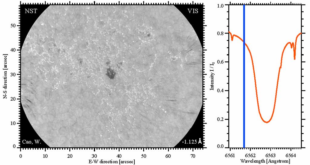
4 NST-VIS Spectroscopy

5 . Interference Filters Interference filters are multilayer thin-film devices. An optical filter consists of multiple layers of evaporated coatings on a substrate, whose spectral properties are the result of wavelength interference rather than absorption. Provide a passband of a few to hundreds angstroms Interference filter category Interference filter structure Interference filter principal Interference filter terminology Use an interference filter in a right way Choose a right interference filter

 of light spectrum.")

6 Interference Filter Category Short Wavelength Pass: transmits visible light of lower wavelengths and block light with higher wavelengths. Long Wavelength Pass: allows light of longer wavelengths to pass through it and effectively block shorter wavelengths. Band Pass: transmit one particular region (or band) of light spectrum. It passes only a very narrow region of wavelengths and blocks a majority of light incident upon the filter surface. Sharp Cutting: eliminates spectral regions, such as the infrared, hot rejector. Broad Band: transmit one particular region (or band) of light spectrum. It usually has rather broad transmission characteristics and passes a significant number of wavelengths. Courtesy: micro.magnet.fsu.edu

7 Interference Filter Structure Interference filters are designed to provide constructive or destructive interference of light by taking advantage of the refraction of light through different materials. Glass substrates Multilayer thin-film coatings are applied to substrates. Single cavity bandpass filter Spacer: the gap between the reflecting surfaces is a thin film of dielectric material, with a thickness of one-half wave at the desired peak transmission wavelength. Reflection layers: consist of several film layers, each of which is a quarterwave thick. Multi-layer blocking filter Optical epoxy and protective metal ring Courtesy: micro.magnet.fsu.edu
 Start from a Fabry-Perot etalon AB CD d cos (d cos ) / m m d cos / Constructive interference occurs when m,, 3... Zero transmission occurs when m /, 3/, 5/.")
8 Spacer FP Resonator Spacer: the gap between the reflecting surfaces is a thin film of dielectric material, with a thickness of one-half wave at the desired peak transmission wavelength. (d = 0 /) Start from a Fabry-Perot etalon AB CD d cos (d cos ) / m m d cos / Constructive interference occurs when m,, 3... Zero transmission occurs when m /, 3/, 5/... Consider d = 0 / and the normal incidence trans 0 d cos cos 0 0 How about the light of 0?
 / m m t cos / Constructive interference occurs when m,, 3... Destructive interference occurs when Then m /, 3/.")
9 Reflection Layers - Thin-films Reflection layers: consist of several film layers, each of which is a quarterwave thick (t = /4), acting as anti-reflection optical coating. Consider reflection by a film layer (t cos ) / m m t cos / Constructive interference occurs when m,, 3... Destructive interference occurs when Then m /, 3/... m t cos cos 0 m / 4 It is precisely this light cancellation that is exploited for anti-reflective (AR) coating, where no light is reflected (back), therefore all light is transmitted. How about the light of 0?
 coating, where no light is reflected (back), therefore all")

10 Thin-films act as AR Coating It is precisely this light cancellation that is exploited for anti-reflective (AR) coating, where no light is reflected (back), therefore all light is transmitted. A thin-film layer coating of thickness /4 generates a phase difference of half a wavelength for the wave traveling backwards. Courtesy: CVI Melles Griot

11 Principal Summary Reflection layers: consist of several film layers, each of which is a quarter-wave thick (d = /4). With the reflected rays being effectively cancelled, a thin film of quarter-wave thickness functions as an anti-reflection optical coating. Spacer: the gap between the reflecting surfaces is a thin film of dielectric material, with a thickness of onehalf wave at the desired peak transmission wavelength. (d = /) The gap in spacer determines which wavelengths destructively interfere and which wavelengths are in phase and will ultimately pass through the coatings. This principle strongly attenuates the transmitted intensity of light at wavelengths that are higher or lower than the wavelength of interest.


12 More Detail about Structure Spacer is the gap between the reflecting surfaces, which is a thin film of dielectric material. On either side of this gap are the two reflecting layers, which actually consist of several film layers. This sandwich of quarter-wave layers is made up of an alternating pattern of high and low index material, usually ZnS (n=.35) and cryolite (n=.35). Together, they are called a stack. The number of layers in the stack is adjusted to tailor the width of the bandpass. To sharpen cutoff, it is common practice that several cavities are layered sequentially into a multicavity filter, which dramatically reduces the transmission of out-of-band wavelengths.
: the wavelength at the midpoint of the half power bandwidth (FWHM). Full-Width Half-Maximum (FWHM): the width of the bandpass at one-half of the maximum transmission.")
13 Terminology Bandpass: the range (or band) of wavelengths passed by a wavelength-selective optic. Blocking: the degree of light attenuation at wavelengths outside the passband of filter. Center Wavelength (CWL): the wavelength at the midpoint of the half power bandwidth (FWHM). Full-Width Half-Maximum (FWHM): the width of the bandpass at one-half of the maximum transmission. Peak Transmission: the maximum percentage transmission within the passband. Filter Cavity: An optical "sandwich" of two partially reflective substrate layers separated by an evaporated coating which forms the dielectric spacer layer. Courtesy: micro.magnet.fsu.edu


14 Performance Transmitted distortion: the distortion of a plane wavefront passing through the filter, and is also measured in fractions or multiples of a wavelength. Wedge: angular deviation from parallelism between the outer filter surfaces, which is measured in aresecond or are-minutes of the deviation angle. Angle shift: the wavelength of CWL at small angle from normal incidence is n 0 0 sin n e where n 0 = in air, n e is refractive index of spacer material. Temperature: an interference filter is slightly temperature dependent, causing transmission spectrum shifts slightly to longer wavelengths with increasing temperature. Orientation: the shiniest side toward the source. Courtesy: CVI Melles Griot


15 Select a Right Filter Courtesy: Han Uitenbroek


16 . Lyot Filters Bernard Lyot Lyot filter, named for its inventor Bernard Lyot, is a type of optical filter that uses birefringence to produce a narrow passband of transmitted wavelengths. Lyot filters are often used in astronomy, particularly for solar astronomy. Provide a passband of a quarter to a few of angstroms Ha 6563 Å SDO - HMI FeI 673 Å HeI 083 nm BBSO FWHM: 0.5 Å FWHM: Å BBSO FWHM: 0.5 Å

17 Birefringence Birefringence, or double refraction, is the decomposition of a ray of light into two rays when it passes through certain anisotropic material (birefringent crystal), such as crystals of calcite. When a beam of light is incident on a birefringent crystal, the waves are split upon entry into orthogonal polarized components: ordinary and extraordinary. o and e components travel through the molecular lattice along different pathways, depending on their orientation with respect to the crystalline optical axis. Light passing through a birefringent crystal Parallel entry: o and e wavefront coincide in amplitude, phase, and trajectory during their journey in the crystal. Oblique entry: o and e diverge and follow different pathways, and o wave travels faster then e wave. Perpendicular entry: divergence between o and e is eliminated, but o wave still travels at a higher speed than does e wave. no n e
18 Birefringence and Interference Perpendicular entry: the propagation speed of o and e wave differ. Birefringent index of a crystal is defined as ne n o o and e wave travel through a crystal of thickness d with a phase delay ( OPL) d ( n n ) e o d Consider a birefringent crystal of a thickness of d, which is placed between two linear polarizers with the same polarization direction. Assume the optical axis of the crystal is 45 with respect to the polarization directions, then the transmitted light is given by T cos ( ) cos d ( ) cos ( )
19 Transmission Profiles What does the transmission profile look like? d T cos ( ) cos ( ) cos ( ) What does the transmission profile look like if d = d? d T cos ( ) cos ( ) cos ( ) cos ( ) d 3 = d = 4d? d 4 = 8d?
20 Lyot Filter Transmission Profiles T TT T T cos cos 3 d d d3 d 4 ( )cos ( )cos ( )cos ( ) ( )cos ( )cos (4 )cos (8 ) 4
21 FWHM and FSR Full Width at Half Maximum (FWHM): is determined by the thickness of the thickest stage d thick. 0.7@ 590nm FWHM d thick Free Spectral Range (FSR): is determined by the thickness of the thinnest stage d thin. FSR d thin For a Lyot filter with n stages, d thick = (n)d thin, so 590 nm d thick FWHM? 0.05 nm FSR (4n) d thin FWHM FSR FWHM
22 Lyot Filter Tuning Wavelength tuning is a critical feature to calibration, fabrication and operation. Each stage needs its individual tuning system. A quarter waveplate, which follows the crystal to be 45 with respect to the optical axis, is followed by a rotating polarizer or a rotating half waveplate. T cos d ( ) cos ( ) T cos d ( ) cos ( )


23 BBSO NIR Lyot Filter Design Requirement Working Wavelength: Clear Aperture: Passband FWHM: Tunable Range: Peak Transmission: Internal Structure: Thermal Controller: Minimum tunable step: Fe I.5648 &.565 m ~ 37 mm.5 Å ± 7 Å ~ 8 % for non-polarized light 4-module ± C 0.0 Å

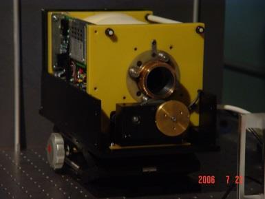
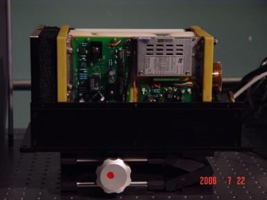
24 Optical and Mechanical Design


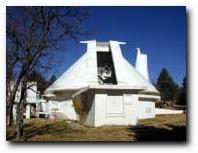
25 System Calibration John W. Evans Solar Facility National Solar Observatory/Sacramento Peak July 006 IR Camera Grating Iris L L L3 Lyot L4 Slit L5

26 ) ( cos ) ( cos ) ( cos ) ( cos d d d d T T T T T System Calibration
27 Transmission Profiles

28 Order Sorting Filter


29 He I nm Lyot Filter Design Requirement Working Wavelength: Clear Aperture: Passband FWHM: Tunable Range: Peak Transmission: Internal Structure: Thermal Controller: Minimum tunable step: He I 083 nm ~ 37 mm 0.5 Å ± 4 Å ~ 8 % for non-polarized light 8-module ± C 0.0 Å A M. flare on August 7, 03


30 3. Fabry-Perot Interferometer Fabry-Perot interferometer (FPI), also called Fabry-Perot etalon is made of two semi-reflecting plates of glass, parallel, producing an interference pattern. IC Optical System Ltd.


31 How does a FPI work? Start from a Fabry-Perot etalon AB CD nd cos m nd cos Constructive interference occurs when m,, 3... Destructive interference occurs when m /, 3/, 5/...


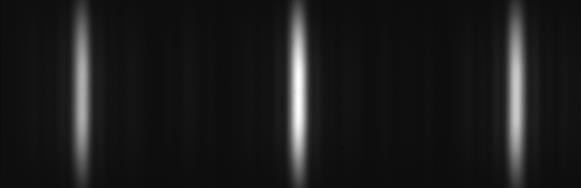
32 Interference Fringe When a FPI is illuminated by a monochromatic extended source m? When a FPI is illuminated by a polychromatic extended source m nd cos Constructive interference occurs when m,, 3... When incident angles are fixed, transmitted wavelength depends on the spacing of a FPI.
 cos ( d ] ) (.")
33 Transmission Profile The amplitude E t (m) of the resultant electric vector of transmitted light is given by The energy transmission coefficient for the pair of surfaces: The energy reflection coefficient for the pair of surfaces: / ) cos ( d ] ) (... [ ) ( ) ( m i m i t e r r e r r t t m E ) /( ) ( i t t e r r t t E E ) cos ( * r r r r t t E E I t t t )] ( sin [ )] ( [ ) ( )]sin ( [4 ) ( ) cos ( F R T R R R T R R T I T )] ( sin )[ ( sin F F I R ) ( ) ( T R r r R t t T ) /( 4 R R F
34 Transmission Profile Consider absorption The energy transmission coefficient for the pair of surfaces: I T I 0 [ T [( R A) [ A ( R)] [ F sin ( R)] [ F sin ( R)] [ F sin When = m, constructive interference occur I A R T When = m, destructive interference occur, I ( )] ( )] ( )] max I0[ A/( R)] I0T /( R) min I0[ A/( R)] /( F) I0T /( R) (nd cos ) /
35 FWHM, FSR and Finesse Full width at half maximum (FWHM): ( R) fwhm nd cos R Free spectral range (FSR): fsr nd cos m Finesse: N R fsr fwhm R R Resolving power: m nd cos mn nd cos R N R


36 ICOS ET70FS-04 ICOS FPI Specification Etalon Model: Working Wavelength: Clear Aperture: Nominal Finesse: Controller Model: Cavity Spacing: Cavity Scan Range: Plate Flatness: ET70FS ~ 700 nm ~ 70 mm 6563 nm CS d = 496 m > 4 m > / 00 before coating

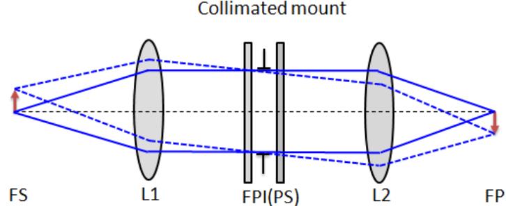
37 Optical Setup m nd cos
 Fe I (630. ± 0.5 nm) NaD (588.9 ± 0.")
38 Visible Imaging Spectrometer Single Fabry-Pérot etalon (D = 70 mm) plus narrow band interference filter Wavelength coverage: nm Band pass: 5.8 pm Telecentric configuration with F/0 Available spectral lines: H (656.3 ± 0.5 nm) Fe I (630. ± 0.5 nm) NaD (588.9 ± 0.5 nm) more lines are coming as needed Field of view: 75 (H) by 64 (V) High speed computer with SSD HDs Spectroscopy cadence: a points scan with multi-frames selection: < 5 secs
Absentee layer. A layer of dielectric material, transparent in the transmission region of
 Glossary of Terms A Absentee layer. A layer of dielectric material, transparent in the transmission region of the filter, due to a phase thickness of 180. Absorption curve, absorption spectrum. The relative
Bandpass Interference Filters
 Precise control of center wavelength and bandpass shape Wide selection of stock wavelengths from 250 nm-1550 nm Selection of bandwidths Available in 1/2 and 1 sizes High peak transmission values Excellent
In their earliest form, bandpass filters
 Bandpass Filters Past and Present Bandpass filters are passive optical devices that control the flow of light. They can be used either to isolate certain wavelengths or colors, or to control the wavelengths
instruments Solar Physics course lecture 3 May 4, 2010 Frans Snik BBL 415 (710)
") Solar Physics course lecture 3 May 4, 2010 Frans Snik BBL 415 (710) f.snik@astro.uu.nl www.astro.uu.nl/~snik info from photons spatial (x,y) temporal (t) spectral (λ) polarization ( ) usually photon starved
Solar Physics course lecture 3 May 4, 2010 Frans Snik BBL 415 (710) f.snik@astro.uu.nl www.astro.uu.nl/~snik info from photons spatial (x,y) temporal (t) spectral (λ) polarization ( ) usually photon starved
Advanced Features of InfraTec Pyroelectric Detectors
 1 Basics and Application of Variable Color Products The key element of InfraTec s variable color products is a silicon micro machined tunable narrow bandpass filter, which is fully integrated inside the
CHAPTER 5 FINE-TUNING OF AN ECDL WITH AN INTRACAVITY LIQUID CRYSTAL ELEMENT
 CHAPTER 5 FINE-TUNING OF AN ECDL WITH AN INTRACAVITY LIQUID CRYSTAL ELEMENT In this chapter, the experimental results for fine-tuning of the laser wavelength with an intracavity liquid crystal element
6545(Print), ISSN (Online) Volume 4, Issue 2, March April (2013), IAEME & TECHNOLOGY (IJEET)
, ISSN (Online) Volume 4, Issue 2, March April (2013), IAEME & TECHNOLOGY (IJEET)") INTERNATIONAL International Journal of JOURNAL Electrical Engineering OF ELECTRICAL and Technology (IJEET), ENGINEERING ISSN 976 6545(Print), ISSN 976 6553(Online) Volume 4, Issue, March April (3), IAEME
INTERNATIONAL International Journal of JOURNAL Electrical Engineering OF ELECTRICAL and Technology (IJEET), ENGINEERING ISSN 976 6545(Print), ISSN 976 6553(Online) Volume 4, Issue, March April (3), IAEME
Flat Top, Ultra-Narrow Band Pass Optical Filters Using Plasma Deposited Hard Oxide Coatings
 Flat Top, Ultra-Narrow Band Pass Optical Filters Using Plasma Deposited Hard Oxide Coatings Alluxa Engineering Staff September 2012 0 1 0.1 1 cav 2 cav 3 cav 4 cav 5 cav 0.01 0.001 635 636 637 638 639
Anti-reflection Coatings
 Spectral Dispersion Spectral resolution defined as R = Low 10-100 Medium 100-1000s High 1000s+ Broadband filters have resolutions of a few (e.g. J-band corresponds to R=4). Anti-reflection Coatings Significant
UTA EE5380 PhD Diagnosis Exam (Fall 2011) Principles of Photonics and Optical Engineering
 Principles of Photonics and Optical Engineering") EE 5380 Fall 2011 PhD Diagnosis Exam ID: UTA EE5380 PhD Diagnosis Exam (Fall 2011) Principles of Photonics and Optical Engineering Instructions: Verify that your exam contains 7 pages (including the cover
EE 5380 Fall 2011 PhD Diagnosis Exam ID: UTA EE5380 PhD Diagnosis Exam (Fall 2011) Principles of Photonics and Optical Engineering Instructions: Verify that your exam contains 7 pages (including the cover
Electronically tunable fabry-perot interferometers with double liquid crystal layers
 Electronically tunable fabry-perot interferometers with double liquid crystal layers Kuen-Cherng Lin *a, Kun-Yi Lee b, Cheng-Chih Lai c, Chin-Yu Chang c, and Sheng-Hsien Wong c a Dept. of Computer and
A novel tunable diode laser using volume holographic gratings
 A novel tunable diode laser using volume holographic gratings Christophe Moser *, Lawrence Ho and Frank Havermeyer Ondax, Inc. 85 E. Duarte Road, Monrovia, CA 9116, USA ABSTRACT We have developed a self-aligned
R.B.V.R.R. WOMEN S COLLEGE (AUTONOMOUS) Narayanaguda, Hyderabad.
 Narayanaguda, Hyderabad.") R.B.V.R.R. WOMEN S COLLEGE (AUTONOMOUS) Narayanaguda, Hyderabad. DEPARTMENT OF PHYSICS QUESTION BANK FOR SEMESTER III PAPER III OPTICS UNIT I: 1. MATRIX METHODS IN PARAXIAL OPTICS 2. ABERATIONS UNIT II
R.B.V.R.R. WOMEN S COLLEGE (AUTONOMOUS) Narayanaguda, Hyderabad. DEPARTMENT OF PHYSICS QUESTION BANK FOR SEMESTER III PAPER III OPTICS UNIT I: 1. MATRIX METHODS IN PARAXIAL OPTICS 2. ABERATIONS UNIT II
Chap. 8. Electro-Optic Devices
 Chap. 8. Electro-Optic Devices - The effect of an applied electric field on the propagation of em radiation. - light modulators, spectral tunable filters, electro-optical filters, beam deflectors 8.1.
Introduction to the operating principles of the HyperFine spectrometer
 Introduction to the operating principles of the HyperFine spectrometer LightMachinery Inc., 80 Colonnade Road North, Ottawa ON Canada A spectrometer is an optical instrument designed to split light into
PREPARED BY: I. Miller DATE: 2004 May 23 CO-OWNERS REVISED DATE OF ISSUE/CHANGED PAGES
 Page 1 of 30 LIGHTMACHINERY TEST REPORT LQT 30.11-1 TITLE: HMI Michelson Interferometer Test Report Serial Number 1 - Wideband FSR INSTRUCTION OWNER HMI Project Manager PREPARED BY: I. Miller DATE: 2004
06SurfaceQuality.nb Optics James C. Wyant (2012) 1
 1") 06SurfaceQuality.nb Optics 513 - James C. Wyant (2012) 1 Surface Quality SQ-1 a) How is surface profile data obtained using the FECO interferometer? Your explanation should include diagrams with the appropriate
06SurfaceQuality.nb Optics 513 - James C. Wyant (2012) 1 Surface Quality SQ-1 a) How is surface profile data obtained using the FECO interferometer? Your explanation should include diagrams with the appropriate
Observational Astronomy
 Observational Astronomy Instruments The telescope- instruments combination forms a tightly coupled system: Telescope = collecting photons and forming an image Instruments = registering and analyzing the
Tunable narrow-band filter for imaging polarimetry
 **FULL TITLE** ASP Conference Series, Vol. **VOLUME**, **YEAR OF PUBLICATION** **NAMES OF EDITORS** Tunable narrow-band filter for imaging polarimetry A. Feller 1, A. Boller 1, J.O. Stenflo 1,2 1 Institute
Large aperture tunable ultra narrow band Fabry-Perot-Bragg filter
 Large aperture tunable ultra narrow band Fabry-Perot-Bragg filter Julien Lumeau *, Vadim Smirnov, Fabien Lemarchand 3, Michel Lequime 3 and Leonid B. Glebov School of Optics/CREOL, University of Central
HUYGENS PRINCIPLE AND INTERFERENCE
 HUYGENS PRINCIPLE AND INTERFERENCE VERY SHORT ANSWER QUESTIONS Q-1. Can we perform Double slit experiment with ultraviolet light? Q-2. If no particular colour of light or wavelength is specified, then
DWDM FILTERS; DESIGN AND IMPLEMENTATION
 DWDM FILTERS; DESIGN AND IMPLEMENTATION 1 OSI REFERENCE MODEL PHYSICAL OPTICAL FILTERS FOR DWDM SYSTEMS 2 AGENDA POINTS NEED CHARACTERISTICS CHARACTERISTICS CLASSIFICATION TYPES PRINCIPLES BRAGG GRATINGS
Theoretical Design of Picoseconds Fabry Pérot Filter and Study the Dispersion using Coupled Mode Equation
 International Journal of Physics and Applications. ISSN 974-33 Volume 5, Number (3), pp. 47-57 International Research Publication House http://www.irphouse.com Theoretical Design of Picoseconds Fabry Pérot
Constructing a Confocal Fabry-Perot Interferometer
 Constructing a Confocal Fabry-Perot Interferometer Michael Dapolito and Eric Wu Laser Teaching Center Department of Physics and Astronomy, Stony Brook University Stony Brook, NY 11794 July 9, 2018 Introduction
Interference [Hecht Ch. 9]
![Interference [Hecht Ch. 9]](/thumbs/79/79365345.jpg "Interference [Hecht Ch. 9]") Interference [Hecht Ch. 9] Note: Read Ch. 3 & 7 E&M Waves and Superposition of Waves and Meet with TAs and/or Dr. Lai if necessary. General Consideration 1 2 Amplitude Splitting Interferometers If a lightwave
Interference [Hecht Ch. 9] Note: Read Ch. 3 & 7 E&M Waves and Superposition of Waves and Meet with TAs and/or Dr. Lai if necessary. General Consideration 1 2 Amplitude Splitting Interferometers If a lightwave
Filters. Edgepass Filters Introduction to Edgepass Interference Filters 96 Long Pass Interference Filters 97 Short Pass Interference Filters 97
 Bandpass Introduction to Bandpass Interference 90-91 UV Bandpass 92 Visible Bandpass 92-93 IR Bandpass 94-95 Bandpass Filter Sets 95 Edgepass Introduction to Edgepass Interference 96 Long Pass Interference
Optical Communications and Networking 朱祖勍. Sept. 25, 2017
 Optical Communications and Networking Sept. 25, 2017 Lecture 4: Signal Propagation in Fiber 1 Nonlinear Effects The assumption of linearity may not always be valid. Nonlinear effects are all related to
PREPARED BY: I. Miller DATE: 2004 May 23 CO-OWNERS REVISED DATE OF ISSUE/CHANGED PAGES
 Page 1 of 30 LIGHTMACHINERY TEST REPORT LQT 30.11-2 TITLE: HMI Michelson Interferometer Test Report Serial Number 2 - Narrowband FSR INSTRUCTION OWNER HMI Project Manager PREPARED BY: I. Miller DATE: 2004
Experimental Physics. Experiment C & D: Pulsed Laser & Dye Laser. Course: FY12. Project: The Pulsed Laser. Done by: Wael Al-Assadi & Irvin Mangwiza
 Experiment C & D: Course: FY1 The Pulsed Laser Done by: Wael Al-Assadi Mangwiza 8/1/ Wael Al Assadi Mangwiza Experiment C & D : Introduction: Course: FY1 Rev. 35. Page: of 16 1// In this experiment we
Lecture 21. Wind Lidar (3) Direct Detection Doppler Lidar
 Direct Detection Doppler Lidar") Lecture 21. Wind Lidar (3) Direct Detection Doppler Lidar Overview of Direct Detection Doppler Lidar (DDL) Resonance fluorescence DDL Fringe imaging DDL Scanning FPI DDL FPI edge-filter DDL Absorption
Lecture 21. Wind Lidar (3) Direct Detection Doppler Lidar Overview of Direct Detection Doppler Lidar (DDL) Resonance fluorescence DDL Fringe imaging DDL Scanning FPI DDL FPI edge-filter DDL Absorption
Bandpass Edge Dichroic Notch & More
 Edmund Optics BROCHURE Filters COPYRIGHT 217 EDMUND OPTICS, INC. ALL RIGHTS RESERVED 1/17 Bandpass Edge Dichroic Notch & More Contact us for a Stock or Custom Quote Today! USA: +1-856-547-3488 EUROPE:
Physical Optics. Diffraction.
 Physical Optics. Diffraction. Interference Young s interference experiment Thin films Coherence and incoherence Michelson interferometer Wave-like characteristics of light Huygens-Fresnel principle Interference.
Measuring optical filters
 Measuring optical filters Application Note Author Don Anderson and Michelle Archard Agilent Technologies, Inc. Mulgrave, Victoria 3170, Australia Introduction Bandpass filters are used to isolate a narrow
IntroOptical Filters. Windows
 IntroOptical Filters Filter Specifications............ 286 Filter Selection Guide........... 288 Custom and Image Filters........ 291 Interference Filters............. 292 High Rejection Laser Line Filters...
Will contain image distance after raytrace Will contain image height after raytrace
 Name: LASR 51 Final Exam May 29, 2002 Answer all questions. Module numbers are for guidance, some material is from class handouts. Exam ends at 8:20 pm. Ynu Raytracing The first questions refer to the
Photonics and Optical Communication
 Photonics and Optical Communication (Course Number 300352) Spring 2007 Dr. Dietmar Knipp Assistant Professor of Electrical Engineering http://www.faculty.iu-bremen.de/dknipp/ 1 Photonics and Optical Communication
ECEN. Spectroscopy. Lab 8. copy. constituents HOMEWORK PR. Figure. 1. Layout of. of the
 ECEN 4606 Lab 8 Spectroscopy SUMMARY: ROBLEM 1: Pedrotti 3 12-10. In this lab, you will design, build and test an optical spectrum analyzer and use it for both absorption and emission spectroscopy. The
Chapter Ray and Wave Optics
 109 Chapter Ray and Wave Optics 1. An astronomical telescope has a large aperture to [2002] reduce spherical aberration have high resolution increase span of observation have low dispersion. 2. If two
BARR ASSOCIATES, INC.
 BARR ASSOCIATES, INC. ULTRA-NARROW BANDPASS FILTERS Overview: Barr offers bandpass filters with bandwidth at Full Width Half Maximum (FWHM) selectable from Wideband to Ultra-Narrowband, manufactured to
Numerical analysis of a swift, high resolution wavelength monitor designed as a Generic Lightwave Integrated Chip (GLIC)
") Numerical analysis of a swift, high resolution wavelength monitor designed as a Generic Lightwave Integrated Chip (GLIC) John Ging and Ronan O Dowd Optoelectronics Research Centre University College Dublin,
Numerical analysis of a swift, high resolution wavelength monitor designed as a Generic Lightwave Integrated Chip (GLIC) John Ging and Ronan O Dowd Optoelectronics Research Centre University College Dublin,
Angela Piegari ENEA, Optical Coatings Laboratory, Roma, Italy
 Optical Filters for Space Instrumentation Angela Piegari ENEA, Optical Coatings Laboratory, Roma, Italy Trieste, 18 February 2015 Optical Filters Optical Filters are commonly used in Space instruments
Filters for Dual Band Infrared Imagers
 Filters for Dual Band Infrared Imagers Thomas D. Rahmlow, Jr.* a, Jeanne E. Lazo-Wasem a, Scott Wilkinson b, and Flemming Tinker c a Rugate Technologies, Inc., 353 Christian Street, Oxford, CT 6478; b
PREPARED BY: I. Miller DATE: 2004 May 23 CO-OWNERS REVISED DATE OF ISSUE/CHANGED PAGES
 Page 1 of 34 LIGHTMACHINERY TEST REPORT LQT 30.11-3 TITLE: HMI Michelson Interferometer Test Report Serial Number 3 wide band FSR INSTRUCTION OWNER HMI Project Manager PREPARED BY: I. Miller DATE: 2004
SUPPLEMENTARY INFORMATION
 Optically reconfigurable metasurfaces and photonic devices based on phase change materials S1: Schematic diagram of the experimental setup. A Ti-Sapphire femtosecond laser (Coherent Chameleon Vision S)
Spectroscopy in the UV and Visible: Instrumentation. Spectroscopy in the UV and Visible: Instrumentation
 Spectroscopy in the UV and Visible: Instrumentation Typical UV-VIS instrument 1 Source - Disperser Sample (Blank) Detector Readout Monitor the relative response of the sample signal to the blank Transmittance
transmission and reflection characteristics across the spectrum. 4. Neutral density
 1. Interference Filters 2. Color SubstrateFilters Narrow band (±10nm),Broadband (±50nm and ±80nm), it has extremely angle sensitive, so carefully mounting is necessary. The highly selective reduce the
The Wave Nature of Light
 The Wave Nature of Light Physics 102 Lecture 7 4 April 2002 Pick up Grating & Foil & Pin 4 Apr 2002 Physics 102 Lecture 7 1 Light acts like a wave! Last week we saw that light travels from place to place
SELECTION GUIDE MULTIPLE-ORDER QUARTZ WAVEPLATES ZERO-ORDER QUARTZ WAVEPLATES DUAL-WAVELENGTH WAVEPLATES... 85
 WAVEPLATES Mirrors Waveplates are used in applications where the control, synthesis, or analysis of the polarization state of an incident beam of light is required. Our waveplates are constructed of very
Where Image Quality Begins
 Where Image Quality Begins Filters are a Necessity Not an Accessory Inexpensive Insurance Policy for the System The most cost effective way to improve repeatability and stability in any machine vision
Chapter 36: diffraction
 Chapter 36: diffraction Fresnel and Fraunhofer diffraction Diffraction from a single slit Intensity in the single slit pattern Multiple slits The Diffraction grating X-ray diffraction Circular apertures
Southern African Large Telescope. Prime Focus Imaging Spectrograph. Polarimetric Optics Design Study
 Southern African Large Telescope Prime Focus Imaging Spectrograph Polarimetric Optics Design Study Kenneth Nordsieck University of Wisconsin Revision 1.1 5 Oct 2001 SALT PFIS/IMPALAS Polarimetric Optics
Lecture 5: Polarisation of light 2
 Lecture 5: Polarisation of light 2 Lecture aims to explain: 1. Circularly and elliptically polarised light 2. Optical retarders - Birefringence - Quarter-wave plate, half-wave plate Circularly and elliptically
Astro 500 A500/L-20 1
 Astro 500 1 Lecture Outline Spectroscopy from a 3D Perspective ü Basics of spectroscopy and spectrographs ü Fundamental challenges of sampling the data cube Approaches and example of available instruments
CVI LASER OPTICS ANTIREFLECTION COATINGS
 CVI LASER OPTICS ANTIREFLECTION COATINGS BROADBAND MULTILAYER ANTIREFLECTION COATINGS Broadband antireflection coatings provide a very low reflectance over a broad spectral bandwidth. These advanced multilayer
Characteristics of point-focus Simultaneous Spatial and temporal Focusing (SSTF) as a two-photon excited fluorescence microscopy
 as a two-photon excited fluorescence microscopy") Characteristics of point-focus Simultaneous Spatial and temporal Focusing (SSTF) as a two-photon excited fluorescence microscopy Qiyuan Song (M2) and Aoi Nakamura (B4) Abstracts: We theoretically and experimentally
Characteristics of point-focus Simultaneous Spatial and temporal Focusing (SSTF) as a two-photon excited fluorescence microscopy Qiyuan Song (M2) and Aoi Nakamura (B4) Abstracts: We theoretically and experimentally
Diffraction. Interference with more than 2 beams. Diffraction gratings. Diffraction by an aperture. Diffraction of a laser beam
 Diffraction Interference with more than 2 beams 3, 4, 5 beams Large number of beams Diffraction gratings Equation Uses Diffraction by an aperture Huygen s principle again, Fresnel zones, Arago s spot Qualitative
Lecture Outline Chapter 28. Physics, 4 th Edition James S. Walker. Copyright 2010 Pearson Education, Inc.
 Lecture Outline Chapter 28 Physics, 4 th Edition James S. Walker Chapter 28 Physical Optics: Interference and Diffraction Units of Chapter 28 Superposition and Interference Young s Two-Slit Experiment
New Optics for Astronomical Polarimetry
 New Optics for Astronomical Polarimetry Located in Colorado USA Topics Components for polarization control and polarimetry Organic materials Liquid crystals Birefringent polymers Microstructures Metrology
Section 1: SPECTRAL PRODUCTS
 Section 1: Optical Non-dispersive Wavelength Selection Filter Based Filter Filter Fundamentals Filter at an Incidence Angle Filters and Environmental Conditions Dispersive Instruments Grating and Polychromators
CHAPTER 7. Components of Optical Instruments
 CHAPTER 7 Components of Optical Instruments From: Principles of Instrumental Analysis, 6 th Edition, Holler, Skoog and Crouch. CMY 383 Dr Tim Laurens NB Optical in this case refers not only to the visible
Infrared broadband 50%-50% beam splitters for s- polarized light
 University of New Orleans ScholarWorks@UNO Electrical Engineering Faculty Publications Department of Electrical Engineering 7-1-2006 Infrared broadband 50%-50% beam splitters for s- polarized light R.
Achievement of Arbitrary Bandwidth of a Narrow Bandpass Filter
 Achievement of Arbitrary Bandwidth of a Narrow Bandpass Filter Cheng-Chung ee, Sheng-ui Chen, Chien-Cheng Kuo and Ching-Yi Wei 2 Department of Optics and Photonics/ Thin Film Technology Center, National
Chapter 16 Light Waves and Color
 Chapter 16 Light Waves and Color Lecture PowerPoint Copyright The McGraw-Hill Companies, Inc. Permission required for reproduction or display. What causes color? What causes reflection? What causes color?
ABC Math Student Copy. N. May ABC Math Student Copy. Physics Week 13(Sem. 2) Name. Light Chapter Summary Cont d 2
 Name. Light Chapter Summary Cont d 2") Page 1 of 12 Physics Week 13(Sem. 2) Name Light Chapter Summary Cont d 2 Lens Abberation Lenses can have two types of abberation, spherical and chromic. Abberation occurs when the rays forming an image
Page 1 of 12 Physics Week 13(Sem. 2) Name Light Chapter Summary Cont d 2 Lens Abberation Lenses can have two types of abberation, spherical and chromic. Abberation occurs when the rays forming an image
Chapter 17: Wave Optics. What is Light? The Models of Light 1/11/13
 Chapter 17: Wave Optics Key Terms Wave model Ray model Diffraction Refraction Fringe spacing Diffraction grating Thin-film interference What is Light? Light is the chameleon of the physical world. Under
ECE 185 ELECTRO-OPTIC MODULATION OF LIGHT
 ECE 185 ELECTRO-OPTIC MODULATION OF LIGHT I. Objective: To study the Pockels electro-optic (E-O) effect, and the property of light propagation in anisotropic medium, especially polarization-rotation effects.
Development of a MEMS-based Dielectric Mirror
 Development of a MEMS-based Dielectric Mirror A Report Submitted for the Henry Samueli School of Engineering Research Scholarship Program By ThanhTruc Nguyen June 2001 Faculty Supervisor Richard Nelson
AP B Webreview ch 24 diffraction and interference
 Name: Class: _ Date: _ AP B Webreview ch 24 diffraction and interference Multiple Choice Identify the choice that best completes the statement or answers the question.. In order to produce a sustained
Computer Generated Holograms for Optical Testing
 Computer Generated Holograms for Optical Testing Dr. Jim Burge Associate Professor Optical Sciences and Astronomy University of Arizona jburge@optics.arizona.edu 520-621-8182 Computer Generated Holograms
Angela Piegari ENEA, Optical Coatings Laboratory, Roma, Italy
 Optical Filters for Space Instrumentation Angela Piegari ENEA, Optical Coatings Laboratory, Roma, Italy Trieste, 18 February 2015 Optical coatings for Space Instrumentation Spectrometers, imagers, interferometers,
UV/Optical/IR Astronomy Part 2: Spectroscopy
 UV/Optical/IR Astronomy Part 2: Spectroscopy Introduction We now turn to spectroscopy. Much of what you need to know about this is the same as for imaging I ll concentrate on the differences. Slicing the
Supplementary Information for. Surface Waves. Angelo Angelini, Elsie Barakat, Peter Munzert, Luca Boarino, Natascia De Leo,
 Supplementary Information for Focusing and Extraction of Light mediated by Bloch Surface Waves Angelo Angelini, Elsie Barakat, Peter Munzert, Luca Boarino, Natascia De Leo, Emanuele Enrico, Fabrizio Giorgis,
SA210-Series Scanning Fabry Perot Interferometer
 435 Route 206 P.O. Box 366 PH. 973-579-7227 Newton, NJ 07860-0366 FAX 973-300-3600 www.thorlabs.com technicalsupport@thorlabs.com SA210-Series Scanning Fabry Perot Interferometer DESCRIPTION: The SA210
Exercise 8: Interference and diffraction
 Physics 223 Name: Exercise 8: Interference and diffraction 1. In a two-slit Young s interference experiment, the aperture (the mask with the two slits) to screen distance is 2.0 m, and a red light of wavelength
Symmetrically coated pellicle beam splitters for dual quarter-wave retardation in reflection and transmission
 University of New Orleans ScholarWorks@UNO Electrical Engineering Faculty Publications Department of Electrical Engineering 1-1-2002 Symmetrically coated pellicle beam splitters for dual quarter-wave retardation
Chapter 29: Light Waves
 Lecture Outline Chapter 29: Light Waves This lecture will help you understand: Huygens' Principle Diffraction Superposition and Interference Polarization Holography Huygens' Principle Throw a rock in a
The diffraction of light
 7 The diffraction of light 7.1 Introduction As introduced in Chapter 6, the reciprocal lattice is the basis upon which the geometry of X-ray and electron diffraction patterns can be most easily understood
Chapter 28 Physical Optics: Interference and Diffraction
 Chapter 28 Physical Optics: Interference and Diffraction 1 Overview of Chapter 28 Superposition and Interference Young s Two-Slit Experiment Interference in Reflected Waves Diffraction Resolution Diffraction
Application of a Liquid Crystal Tunable Filter to Near-Infrared Spectral Searches
 Application of a Liquid Crystal Tunable Filter to Near-Infrared Spectral Searches Jessica Call and Robert A. Lodder, WD8BTA Department of Chemistry, Advanced Science and Technology Center, University of
A miniature all-optical photoacoustic imaging probe
 A miniature all-optical photoacoustic imaging probe Edward Z. Zhang * and Paul C. Beard Department of Medical Physics and Bioengineering, University College London, Gower Street, London WC1E 6BT, UK http://www.medphys.ucl.ac.uk/research/mle/index.htm
The electric field for the wave sketched in Fig. 3-1 can be written as
 ELECTROMAGNETIC WAVES Light consists of an electric field and a magnetic field that oscillate at very high rates, of the order of 10 14 Hz. These fields travel in wavelike fashion at very high speeds.
University of New Orleans. Jian Liu. Rasheed M.A. Azzam University of New Orleans,
 University of New Orleans ScholarWorks@UNO Electrical Engineering Faculty Publications Department of Electrical Engineering 10-1-1996 Infrared quarter-wave reflection retarders designed with high-spatial-frequency
MASSACHUSETTS INSTITUTE OF TECHNOLOGY Department of Electrical Engineering and Computer Science
 Student Name Date MASSACHUSETTS INSTITUTE OF TECHNOLOGY Department of Electrical Engineering and Computer Science 6.161 Modern Optics Project Laboratory Laboratory Exercise No. 6 Fall 2010 Solid-State
Lecture 25. Wind Lidar (3) Direct Detection Doppler Lidar
 Direct Detection Doppler Lidar") Lecture 25. Wind Lidar (3) Direct Detection Doppler Lidar Overview of Direct Detection Doppler Lidar (DDL) Fringe imaging DDL Scanning FPI DDL FPI edge-filter DDL Iodine absorption-line edge-filter DDL
Lecture 25. Wind Lidar (3) Direct Detection Doppler Lidar Overview of Direct Detection Doppler Lidar (DDL) Fringe imaging DDL Scanning FPI DDL FPI edge-filter DDL Iodine absorption-line edge-filter DDL
Gerhard K. Ackermann and Jurgen Eichler. Holography. A Practical Approach BICENTENNIAL. WILEY-VCH Verlag GmbH & Co. KGaA
 Gerhard K. Ackermann and Jurgen Eichler Holography A Practical Approach BICENTENNIAL BICENTENNIAL WILEY-VCH Verlag GmbH & Co. KGaA Contents Preface XVII Part 1 Fundamentals of Holography 1 1 Introduction
Solution of Exercises Lecture Optical design with Zemax Part 6
 2013-06-17 Prof. Herbert Gross Friedrich Schiller University Jena Institute of Applied Physics Albert-Einstein-Str 15 07745 Jena Solution of Exercises Lecture Optical design with Zemax Part 6 6 Illumination
FFP-TF2 Fiber Fabry-Perot Tunable Filter Technical Reference
 FFP-TF2 Fiber Fabry-Perot Tunable Filter MICRON OPTICS, INC. 1852 Century Place NE Atlanta, GA 3345 Tel. (44) 325-5 Fax. (44) 325-482 Internet: www.micronoptics.com Email: sales@micronoptics.com Rev_A
Swept Wavelength Testing:
 Application Note 13 Swept Wavelength Testing: Characterizing the Tuning Linearity of Tunable Laser Sources In a swept-wavelength measurement system, the wavelength of a tunable laser source (TLS) is swept
TriVista. Universal Raman Solution
 TriVista Universal Raman Solution Why choose the Princeton Instruments/Acton TriVista? Overview Raman Spectroscopy systems can be derived from several dispersive components depending on the level of performance
Order Overlap. A single wavelength constructively interferes in several directions A given direction can receive multiple wavelengths.
 Order Overlap A single wavelength constructively interferes in several directions A given direction can receive multiple wavelengths. Spectral Calibration TripleSpec Users Guide Spectral Calibration TripleSpec
(A) 2f (B) 2 f (C) f ( D) 2 (E) 2
 2f (B) 2 f (C) f ( D) 2 (E) 2") 1. A small vibrating object S moves across the surface of a ripple tank producing the wave fronts shown above. The wave fronts move with speed v. The object is traveling in what direction and with what
1. A small vibrating object S moves across the surface of a ripple tank producing the wave fronts shown above. The wave fronts move with speed v. The object is traveling in what direction and with what
Chapter 24. The Wave Nature of Light
 Ch-24-1 Chapter 24 The Wave Nature of Light Questions 1. Does Huygens principle apply to sound waves? To water waves? Explain how Huygens principle makes sense for water waves, where each point vibrates
University of New Orleans. S. R. Perla. R. M.A. Azzam University of New Orleans,
 University of New Orleans ScholarWorks@UNO Electrical Engineering Faculty Publications Department of Electrical Engineering 9-19-2007 Embedded centrosymmetric multilayer stacks as complete-transmission
Class XII - Physics Wave Optics Chapter-wise Problems
 Class XII - hysics Wave Optics Chapter-wise roblems Multiple Choice Question :- 10.1 Consider a light beam incident from air to a glass slab at Brewster s angle as shown in Fig. 10.1. A polaroid is placed
PHYS 3153 Methods of Experimental Physics II O2. Applications of Interferometry
 Purpose PHYS 3153 Methods of Experimental Physics II O2. Applications of Interferometry In this experiment, you will study the principles and applications of interferometry. Equipment and components PASCO
Lithography. 3 rd. lecture: introduction. Prof. Yosi Shacham-Diamand. Fall 2004
 Lithography 3 rd lecture: introduction Prof. Yosi Shacham-Diamand Fall 2004 1 List of content Fundamental principles Characteristics parameters Exposure systems 2 Fundamental principles Aerial Image Exposure
58 Field of Search ,247, 290, between two thin-metal films to form a Fabry-Perot cavity.
 US006031653A United States Patent (19) 11 Patent Number: Wang (45) Date of Patent: Feb. 29, 2000 54) LOW-COST THIN-METAL-FILM 56) References Cited INTERFERENCE FILTERS 75 Inventor: Yu Wang, Pasadena, Calif.
Exam 4. Name: Class: Date: Multiple Choice Identify the choice that best completes the statement or answers the question.
 Name: Class: Date: Exam 4 Multiple Choice Identify the choice that best completes the statement or answers the question. 1. Mirages are a result of which physical phenomena a. interference c. reflection
Chemistry 524--"Hour Exam"--Keiderling Mar. 19, pm SES
 Chemistry 524--"Hour Exam"--Keiderling Mar. 19, 2013 -- 2-4 pm -- 170 SES Please answer all questions in the answer book provided. Calculators, rulers, pens and pencils permitted. No open books allowed.
Module 19 : WDM Components
 Module 19 : WDM Components Lecture : WDM Components - I Part - I Objectives In this lecture you will learn the following WDM Components Optical Couplers Optical Amplifiers Multiplexers (MUX) Insertion