Antennas and Propagation. Chapter 5
|
|
|
- Byron Barker
- 5 years ago
- Views:
Transcription
1 Antennas and Propagation Chapter 5
2 Introduction An antenna is an electrical conductor or system of conductors Transmission - radiates electromagnetic energy into space Reception - collects electromagnetic energy from space In two-way communication, the same antenna can be used for transmission and reception
3 Radiation Patterns Radiation pattern Graphical representation of radiation properties of an antenna Depicted as two-dimensional cross section Beam width (or half-power beam width) Measure of directivity of antenna The angle within which the power is at least half of the most preferred direction Reception pattern Receiving antenna s equivalent to radiation pattern The longest sections of the pattern indicates the best direction for reception
4
5 Types of Antennas Isotropic antenna (idealized) Radiates power equally in all directions Dipole antennas Half-wave dipole antenna (or Hertz antenna) Quarter-wave vertical antenna (or Marconi antenna) Parabolic Reflective Antenna
6
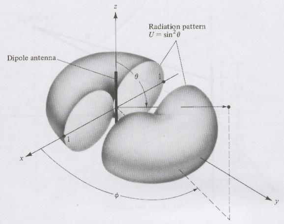
7 y z x
8
9 Antenna Gain Antenna gain A measure of the directionality of an antenna Power output, in a particular direction, compared to that produced in any direction by a perfect omnidirectional antenna (isotropic antenna) Effective area Related to physical size and shape of antenna
10 Antenna Gain Relationship between antenna gain and effective area G = 4πA e 2 λ G = antenna gain A e = effective area f = carrier frequency 4πf c c = speed of light (3 x 10 8 m/s) λ = carrier wavelength Example: pp. 105 = 2 2 A e
11 Propagation Modes Ground-wave propagation Sky-wave propagation Line-of-sight propagation
12 Ground Wave Propagation
13 Ground Wave Propagation Follows contour of the earth Can Propagate considerable distances Frequencies up to 2 MHz Example AM radio
14 Sky Wave Propagation
15 Sky Wave Propagation Signal reflected from ionized layer of atmosphere back down to earth Signal can travel a number of hops, back and forth between ionosphere and earth s surface Reflection effect caused by refraction Examples Amateur radio CB radio
16 Line-of-Sight Propagation
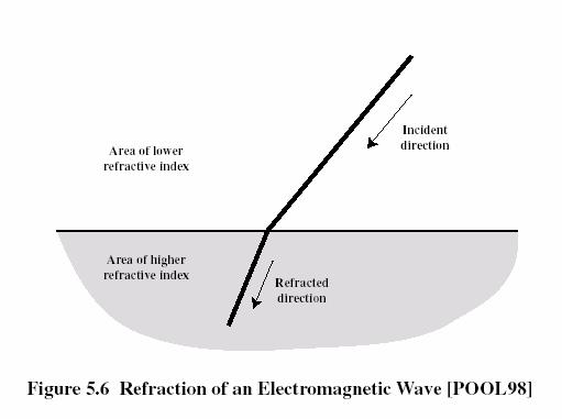
17 Line-of-Sight Propagation Transmitting and receiving antennas must be within line of sight Satellite communication signal above 30 MHz not reflected by ionosphere Ground communication antennas within effective line of sight of each other Refraction bending of microwaves by the atmosphere Velocity of electromagnetic wave is a function of the density of the medium When wave changes medium, speed changes Wave bends at the boundary between mediums
18
19
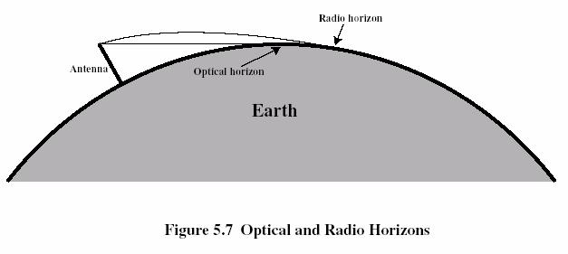
20 Line-of-Sight Equations Optical line of sight d = Effective, or radio, line of sight d = distance between antenna and horizon (km) h = antenna height (m) h d = Κh K = adjustment factor to account for refraction, rule of thumb K = 4/3
21 Line-of-Sight Equations Maximum distance between two antennas for LOS propagation: ( ) 3.57 Κh + Κh h 1 = height of antenna one h 2 = height of antenna two Example: pp. 109 ~
22 LOS Wireless Transmission Impairments Attenuation and attenuation distortion Free space loss Noise Atmospheric absorption Multipath Refraction Thermal noise
23 Attenuation Strength of signal falls off with distance over transmission medium Attenuation factors for unguided media: Received signal must have sufficient strength so that circuitry in the receiver can interpret the signal Signal must maintain a level sufficiently higher than noise to be received without error Attenuation is greater at higher frequencies, causing distortion Use of amplifiers or repeaters to enhance the signal strength
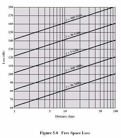
24 Free Space Loss Free space loss, ideal isotropic antenna Pt P r = ( ) 2 4πd ( 4πfd ) 2 λ = P t = signal power at transmitting antenna P r = signal power at receiving antenna λ = carrier wavelength d = propagation distance between antennas c = speed of light ( 3 x 10 8 m/s) where d and λ are in the same units (e.g., meters) c 2 2
25 Free Space Loss Free space loss equation can be recast: L db = 10log Pt P r = 20log 4πd λ ( λ) + 20log( ) db = 20 log d + 4πfd = 20log = 20log d c ( f ) + 20log( ) db
26
27 Free Space Loss Free space loss accounting for gain of other antennas Pt P r = ( ) 2( ) 2 ( ) 2 4π d λd ( cd ) G G r 2 tλ = G t = gain of transmitting antenna G r = gain of receiving antenna A t = effective area of transmitting antenna A r = effective area of receiving antenna A r A t = f 2 A r 2 A t
28 Free Space Loss Free space loss accounting for gain of other antennas can be recast as L db ( ) + 20log( d ) 10log( A A ) = 20log λ t r ( f ) + 20log( d ) 10log( A A t ) dB = r 20 log + Example: pp. 113
29 Categories of Noise Thermal Noise Intermodulation noise Crosstalk Impulse Noise
30 Thermal Noise Thermal noise due to agitation of electrons Present in all electronic devices and transmission media Cannot be eliminated Function of temperature Particularly significant for satellite communication
31 Thermal Noise Amount of thermal noise to be found in a bandwidth of 1Hz in any device or conductor is: N = kt 0 ( W/Hz) N 0 = noise power density in watts per 1 Hz of bandwidth k = Boltzmann's constant = x J/K T = temperature, in kelvins (absolute temperature)
32 Thermal Noise (White Noise) Noise is assumed to be independent of frequency Thermal noise present in a bandwidth of B Hertz (in watts): or, in decibel-watts N N = ktb = 10 log k + 10 log T + 10log B = dbw + 10 log T + 10log B Example: pp. 114
33 Noise Terminology Intermodulation noise occurs if signals with different frequencies share the same medium Interference caused by a signal produced at a frequency that is the sum or difference of original frequencies Crosstalk unwanted coupling between signal paths Impulse noise irregular pulses or noise spikes Short duration and of relatively high amplitude Caused by external electromagnetic disturbances, or faults and flaws in the communications system
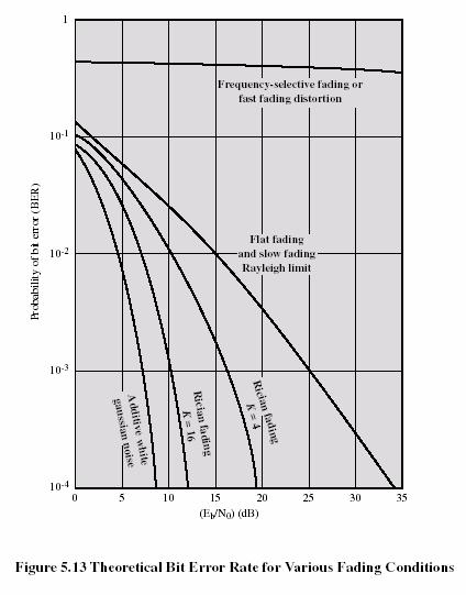
34 Expression E b /N 0 Ratio of signal energy per bit to noise power density per Hertz E b S / R S = = N0 N0 ktr The bit error rate for digital data is a function of E b /N 0 Given a value for E b /N 0 to achieve a desired error rate, parameters of this formula can be selected As bit rate R increases, transmitted signal power must increase to maintain required E b /N 0
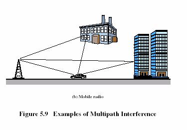
35 Other Impairments Atmospheric absorption water vapor and oxygen contribute to attenuation Multipath obstacles reflect signals so that multiple copies with varying delays are received Refraction bending of radio waves as they propagate through the atmosphere
36
37 Fading in the Mobile Environment Most challenging technical problem in a mobile environment Fading refers to the time variation of received signal power caused by changes in the transmission medium or paths In a mobile environment, the relative location of various obstacles changes over time
38 Multipath Propagation Reflection - occurs when signal encounters a surface that is large relative to the wavelength of the signal Diffraction - occurs at the edge of an impenetrable body that is large compared to wavelength of radio wave Scattering occurs when incoming signal hits an object whose size in the order of the wavelength of the signal or less
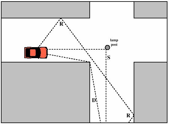
39 Multipath Propagation
40 The Effects of Multipath Propagation Multiple copies of a signal may arrive at different phases If phases add destructively, the signal level relative to noise declines, making detection more difficult Intersymbol interference (ISI) One or more delayed copies of a pulse may arrive at the same time as the primary pulse for a subsequent bit
41
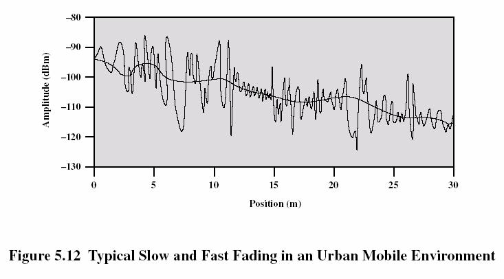
42 Types of Fading Fast fading Slow fading Flat fading Selective fading Rayleigh fading Rician fading
43
44
45 Error Compensation Mechanisms Forward error correction Adaptive equalization Diversity techniques
46 Forward Error Correction Transmitter adds error-correcting code to data block Code is a function of the data bits Receiver calculates error-correcting code from incoming data bits If calculated code matches incoming code, no error occurred If error-correcting codes don t match, receiver attempts to determine bits in error and correct
47 Adaptive Equalization Can be applied to transmissions that carry analog or digital information Analog voice or video Digital data, digitized voice or video Used to combat intersymbol interference Sophisticated digital signal processing algorithms
48 Diversity Techniques Diversity is based on the fact that individual channels experience independent fading events Space diversity techniques involving physical transmission path Frequency diversity techniques where the signal is spread out over a larger frequency bandwidth or carried on multiple frequency carriers Time diversity techniques aimed at spreading the data out over time
49
Antennas and Propagation. Chapter 5
 Antennas and Propagation Chapter 5 Introduction An antenna is an electrical conductor or system of conductors Transmission - radiates electromagnetic energy into space Reception - collects electromagnetic
Antennas and Propagation
 Mobile Networks Module D-1 Antennas and Propagation 1. Introduction 2. Propagation modes 3. Line-of-sight transmission 4. Fading Slides adapted from Stallings, Wireless Communications & Networks, Second
Antennas & Propagation. CSG 250 Fall 2007 Rajmohan Rajaraman
 Antennas & Propagation CSG 250 Fall 2007 Rajmohan Rajaraman Introduction An antenna is an electrical conductor or system of conductors o Transmission - radiates electromagnetic energy into space o Reception
Antennas and Propagation
 Antennas and Propagation Chapter 5 Introduction An antenna is an electrical conductor or system of conductors Transmission - radiates electromagnetic energy into space Reception - collects electromagnetic
Session2 Antennas and Propagation
 Wireless Communication Presented by Dr. Mahmoud Daneshvar Session2 Antennas and Propagation 1. Introduction Types of Anttenas Free space Propagation 2. Propagation modes 3. Transmission Problems 4. Fading
Antennas and Propagation
 CMPE 477 Wireless and Mobile Networks Lecture 3: Antennas and Propagation Antennas Propagation Modes Line of Sight Transmission Fading in the Mobile Environment Introduction An antenna is an electrical
CHAPTER 6 THE WIRELESS CHANNEL
 CHAPTER 6 THE WIRELESS CHANNEL These slides are made available to faculty in PowerPoint form. Slides can be freely added, modified, and deleted to suit student needs. They represent substantial work on
Mobile and Wireless Networks Course Instructor: Dr. Safdar Ali
 Mobile and Wireless Networks Course Instructor: Dr. Safdar Ali BOOKS Text Book: William Stallings, Wireless Communications and Networks, Pearson Hall, 2002. BOOKS Reference Books: Sumit Kasera, Nishit
Antennas and Propagation. Prelude to Chapter 4 Propagation
 Antennas and Propagation Prelude to Chapter 4 Propagation Introduction An antenna is an electrical conductor or system of conductors for: Transmission - radiates electromagnetic energy into space (involves
Channel Modeling and Characteristics
 Channel Modeling and Characteristics Dr. Farid Farahmand Updated:10/15/13, 10/20/14 Line-of-Sight Transmission (LOS) Impairments The received signal is different from the transmitted signal due to transmission
CS-435 spring semester Network Technology & Programming Laboratory. Stefanos Papadakis & Manolis Spanakis
 CS-435 spring semester 2016 Network Technology & Programming Laboratory University of Crete Computer Science Department Stefanos Papadakis & Manolis Spanakis CS-435 Lecture preview Wireless Networking
Data and Computer Communications. Tenth Edition by William Stallings
 Data and Computer Communications Tenth Edition by William Stallings Data and Computer Communications, Tenth Edition by William Stallings, (c) Pearson Education - Prentice Hall, 2013 Wireless Transmission
Project = An Adventure : Wireless Networks. Lecture 4: More Physical Layer. What is an Antenna? Outline. Page 1
 Project = An Adventure 18-759: Wireless Networks Checkpoint 2 Checkpoint 1 Lecture 4: More Physical Layer You are here Done! Peter Steenkiste Departments of Computer Science and Electrical and Computer
Wireless Communication Technology
 PART TWO Wireless Communication Technology CHAPTER5 ANTENNAS AND PROPAGATION 5.1 Antennas Radiation Patterns Antenna Types Antenna Gain 5.2 Propagation Modes Ground Wave Propagation Sky Wave Propagation
Data and Computer Communications Chapter 4 Transmission Media
 Data and Computer Communications Chapter 4 Transmission Media Ninth Edition by William Stallings Data and Computer Communications, Ninth Edition by William Stallings, (c) Pearson Education - Prentice Hall,
Unguided Transmission Media
 CS311 Data Communication Unguided Transmission Media by Dr. Manas Khatua Assistant Professor Dept. of CSE IIT Jodhpur E-mail: manaskhatua@iitj.ac.in Web: http://home.iitj.ac.in/~manaskhatua http://manaskhatua.github.io/
Data and Computer Communications. Chapter 3 Data Transmission
 Data and Computer Communications Chapter 3 Data Transmission Data Transmission quality of the signal being transmitted The successful transmission of data depends on two factors: characteristics of the
Contents. Telecom Service Chae Y. Lee. Data Signal Transmission Transmission Impairments Channel Capacity
 Data Transmission Contents Data Signal Transmission Transmission Impairments Channel Capacity 2 Data/Signal/Transmission Data: entities that convey meaning or information Signal: electric or electromagnetic
Data and Computer Communications Chapter 3 Data Transmission
 Data and Computer Communications Chapter 3 Data Transmission Eighth Edition by William Stallings Transmission Terminology data transmission occurs between a transmitter & receiver via some medium guided
EC 554 Data Communications
 EC 554 Data Communications Mohamed Khedr http://webmail. webmail.aast.edu/~khedraast.edu/~khedr Syllabus Tentatively Week 1 Week 2 Week 3 Week 4 Week 5 Week 6 Week 7 Week 8 Week 9 Week 10 Week 11 Week
EIE339 Digital Transmission and Switching Systems
 EIE339 Digital Transmission and Switching Systems Lecturer: Dr. W.Y.Tam Office: DE604 Telephone no.: 666-665 email address: enwytam@polyu.edu.hk Continuous Assessment Tests 5% Assignments and quizzes 5%
Data Communications and Networks
 Data Communications and Networks Abdul-Rahman Mahmood http://alphapeeler.sourceforge.net http://pk.linkedin.com/in/armahmood abdulmahmood-sss twitter.com/alphapeeler alphapeeler.sourceforge.net/pubkeys/pkey.htm
UNIT Derive the fundamental equation for free space propagation?
 UNIT 8 1. Derive the fundamental equation for free space propagation? Fundamental Equation for Free Space Propagation Consider the transmitter power (P t ) radiated uniformly in all the directions (isotropic),
Noise and Interference Limited Systems
 Chapter 3 Noise and Interference Limited Systems 47 Basics of link budgets Link budgets show how different components and propagation processes influence the available SNR Link budgets can be used to compute
Satellite Signals and Communications Principles. Dr. Ugur GUVEN Aerospace Engineer (P.hD)
") Satellite Signals and Communications Principles Dr. Ugur GUVEN Aerospace Engineer (P.hD) Principle of Satellite Signals In essence, satellite signals are electromagnetic waves that travel from the satellite
Satellite Signals and Communications Principles Dr. Ugur GUVEN Aerospace Engineer (P.hD) Principle of Satellite Signals In essence, satellite signals are electromagnetic waves that travel from the satellite
William Stallings Data and Computer Communications 7 th Edition. Chapter 4 Transmission Media
 William Stallings Data and Computer Communications 7 th Edition Chapter 4 Transmission Media Overview Guided - wire Unguided - wireless Characteristics and quality determined by medium and signal For guided,
L(f) = = (f) G(f) L2(f) Transmission Impairments: Attenuation (cont.)
 = = (f) G(f) L2(f) Transmission Impairments: Attenuation (cont.)") Transmission Impairments: Attenuation (cont.) how many times the put signal has attenuated relative to the input signal should be in L(f) (f) (f) A A in (f) (f) how many times the put signal has been amplified
Transmission Impairments: Attenuation (cont.) how many times the put signal has attenuated relative to the input signal should be in L(f) (f) (f) A A in (f) (f) how many times the put signal has been amplified
Lecture 3: Data Transmission
 Lecture 3: Data Transmission 1 st semester 1439-2017 1 By: Elham Sunbu OUTLINE Data Transmission DATA RATE LIMITS Transmission Impairments Examples DATA TRANSMISSION The successful transmission of data
Lecture 2 Physical Layer - Data Transmission
 DATA AND COMPUTER COMMUNICATIONS Lecture 2 Physical Layer - Data Transmission Mei Yang Based on Lecture slides by William Stallings 1 DATA TRANSMISSION The successful transmission of data depends on two
Terminology (1) Chapter 3. Terminology (3) Terminology (2) Transmitter Receiver Medium. Data Transmission. Simplex. Direct link.
 Chapter 3. Terminology (3) Terminology (2) Transmitter Receiver Medium. Data Transmission. Simplex. Direct link.") Chapter 3 Data Transmission Terminology (1) Transmitter Receiver Medium Guided medium e.g. twisted pair, optical fiber Unguided medium e.g. air, water, vacuum Corneliu Zaharia 2 Corneliu Zaharia Terminology
Chapter 3 Data Transmission Terminology (1) Transmitter Receiver Medium Guided medium e.g. twisted pair, optical fiber Unguided medium e.g. air, water, vacuum Corneliu Zaharia 2 Corneliu Zaharia Terminology
Chapter 3 Data Transmission
 Chapter 3 Data Transmission COSC 3213 Instructor: U.T. Nguyen 1 9/27/2007 3:21 PM Terminology (1) Transmitter Receiver Medium Guided medium e.g. twisted pair, optical fiber Unguided medium e.g. air, water,
Data Transmission. ITS323: Introduction to Data Communications. Sirindhorn International Institute of Technology Thammasat University ITS323
 ITS323: Introduction to Data Communications Sirindhorn International Institute of Technology Thammasat University Prepared by Steven Gordon on 23 May 2012 ITS323Y12S1L03, Steve/Courses/2012/s1/its323/lectures/transmission.tex,
Chapter 3. Mobile Radio Propagation
 Chapter 3 Mobile Radio Propagation Based on the slides of Dr. Dharma P. Agrawal, University of Cincinnati and Dr. Andrea Goldsmith, Stanford University Propagation Mechanisms Outline Radio Propagation
Chapter 3. Data Transmission
 Chapter 3 Data Transmission Reading Materials Data and Computer Communications, William Stallings Terminology (1) Transmitter Receiver Medium Guided medium (e.g. twisted pair, optical fiber) Unguided medium
Data Communication. Chapter 3 Data Transmission
 Data Communication Chapter 3 Data Transmission ١ Terminology (1) Transmitter Receiver Medium Guided medium e.g. twisted pair, coaxial cable, optical fiber Unguided medium e.g. air, water, vacuum ٢ Terminology
Antenna & Propagation. Basic Radio Wave Propagation
 For updated version, please click on http://ocw.ump.edu.my Antenna & Propagation Basic Radio Wave Propagation by Nor Hadzfizah Binti Mohd Radi Faculty of Electric & Electronics Engineering hadzfizah@ump.edu.my
DATA TRANSMISSION. ermtiong. ermtiong
 DATA TRANSMISSION Analog Transmission Analog signal transmitted without regard to content May be analog or digital data Attenuated over distance Use amplifiers to boost signal Also amplifies noise DATA
Chapter 15: Radio-Wave Propagation
 Chapter 15: Radio-Wave Propagation MULTIPLE CHOICE 1. Radio waves were first predicted mathematically by: a. Armstrong c. Maxwell b. Hertz d. Marconi 2. Radio waves were first demonstrated experimentally
Radio Propagation Fundamentals
 Radio Propagation Fundamentals Concept of Electromagnetic Wave Propagation Mechanisms Modes of Propagation Propagation Models Path Profiles Link Budget Fading Channels Electromagnetic (EM) Waves EM Wave
Data Communications & Computer Networks
 Data Communications & Computer Networks Chapter 3 Data Transmission Fall 2008 Agenda Terminology and basic concepts Analog and Digital Data Transmission Transmission impairments Channel capacity Home Exercises
Course 2: Channels 1 1
 Course 2: Channels 1 1 "You see, wire telegraph is a kind of a very, very long cat. You pull his tail in New York and his head is meowing in Los Angeles. Do you understand this? And radio operates exactly
Terminology (1) Chapter 3. Terminology (3) Terminology (2) Transmitter Receiver Medium. Data Transmission. Direct link. Point-to-point.
 Chapter 3. Terminology (3) Terminology (2) Transmitter Receiver Medium. Data Transmission. Direct link. Point-to-point.") Terminology (1) Chapter 3 Data Transmission Transmitter Receiver Medium Guided medium e.g. twisted pair, optical fiber Unguided medium e.g. air, water, vacuum Spring 2012 03-1 Spring 2012 03-2 Terminology
Terminology (1) Chapter 3 Data Transmission Transmitter Receiver Medium Guided medium e.g. twisted pair, optical fiber Unguided medium e.g. air, water, vacuum Spring 2012 03-1 Spring 2012 03-2 Terminology
Introduction to wireless systems
 Introduction to wireless systems Wireless Systems a.a. 2014/2015 Un. of Rome La Sapienza Chiara Petrioli Department of Computer Science University of Rome Sapienza Italy Background- Wireless Systems What
TSEK02: Radio Electronics Lecture 6: Propagation and Noise. Ted Johansson, EKS, ISY
 TSEK02: Radio Electronics Lecture 6: Propagation and Noise Ted Johansson, EKS, ISY 2 Propagation and Noise - Channel and antenna: not in the Razavi book - Noise: 2.3 The wireless channel The antenna Signal
WIRELESS TRANSMISSION
 COMP 635: WIRELESS NETWORKS WIRELESS TRANSMISSION Jasleen Kaur Fall 205 Outline Frequenc Spectrum Ø Usage and Licensing Signals and Antennas Ø Propagation Characteristics Multipleing Ø Space, Frequenc,
COMP211 Physical Layer
 COMP211 Physical Layer Data and Computer Communications 7th edition William Stallings Prentice Hall 2004 Computer Networks 5th edition Andrew S.Tanenbaum, David J.Wetherall Pearson 2011 Material adapted
Chapter-15. Communication systems -1 mark Questions
 Chapter-15 Communication systems -1 mark Questions 1) What are the three main units of a Communication System? 2) What is meant by Bandwidth of transmission? 3) What is a transducer? Give an example. 4)
TSEK02: Radio Electronics Lecture 6: Propagation and Noise. Ted Johansson, EKS, ISY
 TSEK02: Radio Electronics Lecture 6: Propagation and Noise Ted Johansson, EKS, ISY 2 Propagation and Noise - Channel and antenna: not in the Razavi book - Noise: 2.3 The wireless channel The antenna Signal
COMMUNICATION SYSTEMS -I
 COMMUNICATION SYSTEMS -I Communication : It is the act of transmission of information. ELEMENTS OF A COMMUNICATION SYSTEM TRANSMITTER MEDIUM/CHANNEL: The physical medium that connects transmitter to receiver
Chapter 2 Transmission Media and Propagation Mechanisms
 Chapter 2 Transmission Media and Propagation Mechanisms 2.1 Introduction Signals generated by the source need to be transported to the destination over a communication s channel. A communication channel
Vehicle Networks. Wireless communication basics. Univ.-Prof. Dr. Thomas Strang, Dipl.-Inform. Matthias Röckl
 Vehicle Networks Wireless communication basics Univ.-Prof. Dr. Thomas Strang, Dipl.-Inform. Matthias Röckl Outline Wireless Signal Propagation Electro-magnetic waves Signal impairments Attenuation Distortion
Lecture Fundamentals of Data and signals
 IT-5301-3 Data Communications and Computer Networks Lecture 05-07 Fundamentals of Data and signals Lecture 05 - Roadmap Analog and Digital Data Analog Signals, Digital Signals Periodic and Aperiodic Signals
# DEFINITIONS TERMS. 2) Electrical energy that has escaped into free space. Electromagnetic wave
 Electrical energy that has escaped into free space. Electromagnetic wave") CHAPTER 14 ELECTROMAGNETIC WAVE PROPAGATION # DEFINITIONS TERMS 1) Propagation of electromagnetic waves often called radio-frequency (RF) propagation or simply radio propagation. Free-space 2) Electrical
CHAPTER 14 ELECTROMAGNETIC WAVE PROPAGATION # DEFINITIONS TERMS 1) Propagation of electromagnetic waves often called radio-frequency (RF) propagation or simply radio propagation. Free-space 2) Electrical
The Radio Channel. COS 463: Wireless Networks Lecture 14 Kyle Jamieson. [Parts adapted from I. Darwazeh, A. Goldsmith, T. Rappaport, P.
 The Radio Channel COS 463: Wireless Networks Lecture 14 Kyle Jamieson [Parts adapted from I. Darwazeh, A. Goldsmith, T. Rappaport, P. Steenkiste] Motivation The radio channel is what limits most radio
Lecture 3 Concepts for the Data Communications and Computer Interconnection
 Lecture 3 Concepts for the Data Communications and Computer Interconnection Aim: overview of existing methods and techniques Terms used: -Data entities conveying meaning (of information) -Signals data
E-716-A Mobile Communications Systems. Lecture #2 Basic Concepts of Wireless Transmission (p1) Instructor: Dr. Ahmad El-Banna
 Instructor: Dr. Ahmad El-Banna") October 2014 Ahmad El-Banna Integrated Technical Education Cluster At AlAmeeria E-716-A Mobile Communications Systems Lecture #2 Basic Concepts of Wireless Transmission (p1) Instructor: Dr. Ahmad El-Banna
October 2014 Ahmad El-Banna Integrated Technical Education Cluster At AlAmeeria E-716-A Mobile Communications Systems Lecture #2 Basic Concepts of Wireless Transmission (p1) Instructor: Dr. Ahmad El-Banna
Part II Data Communications
 Part II Data Communications Chapter 3 Data Transmission Concept & Terminology Signal : Time Domain & Frequency Domain Concepts Signal & Data Analog and Digital Data Transmission Transmission Impairments
Contents. ITS323: Introduction to Data Communications CSS331: Fundamentals of Data Communications. Transmission Media and Spectrum.
 2 ITS323: Introduction to Data Communications CSS331: Fundamentals of Data Communications Sirindhorn International Institute of Technology Thammasat University Prepared by Steven Gordon on 3 August 2015
ITS323: Introduction to Data Communications CSS331: Fundamentals of Data Communications
 ITS323: Introduction to Data Communications CSS331: Fundamentals of Data Communications Sirindhorn International Institute of Technology Thammasat University Prepared by Steven Gordon on 3 August 2015
Chapter 4: Transmission Media
 Chapter 4: Transmission Media Page 1 Overview Guided - wire Unguided - wireless Characteristics and quality determined by medium and signal For guided, the medium is more important For unguided, the bandwidth
Introduction to Analog And Digital Communications
 Introduction to Analog And Digital Communications Second Edition Simon Haykin, Michael Moher Chapter 11 System and Noise Calculations 11.1 Electrical Noise 11.2 Noise Figure 11.3 Equivalent Noise Temperature
Structure of the Lecture
 Structure of the Lecture Chapter 2 Technical Basics: Layer 1 Methods for Medium Access: Layer 2 Representation of digital signals on an analogous medium Signal propagation Characteristics of antennas Chapter
Transmission Media. Transmission Media 12/14/2016
 Transmission Media in data communications DDE University of Kashmir By Suhail Qadir System Analyst suhailmir@uok.edu.in Transmission Media the transmission medium is the physical path between transmitter
Noise and Propagation mechanisms
 2 Noise and Propagation mechanisms Noise Johnson-Nyquist noise Physical review 1928 V rms2 = 4kTBR k : Bolzmann s constant T : absolute temperature B : bandwidth R : Resistance P=4kTB 1 1 Why is this a
Data Transmission (II)
") Agenda Lecture (02) Data Transmission (II) Analog and digital signals Analog and Digital transmission Transmission impairments Channel capacity Shannon formulas Dr. Ahmed ElShafee 1 Dr. Ahmed ElShafee,
Agenda Lecture (02) Data Transmission (II) Analog and digital signals Analog and Digital transmission Transmission impairments Channel capacity Shannon formulas Dr. Ahmed ElShafee 1 Dr. Ahmed ElShafee,
CS311 -Data Communication Unguided Transmission Media
 CS311 -Data Communication Unguided Transmission Media Dr. Manas Khatua Assistant Professor Dept. of CSE IIT Jodhpur E-mail: manaskhatua@iitj.ac.in INTRODUCTION -Physical Path between transmitter and receiver
CHAPTER -15. Communication Systems
 CHAPTER -15 Communication Systems COMMUNICATION Communication is the act of transmission and reception of information. COMMUNICATION SYSTEM: A system comprises of transmitter, communication channel and
UNIK4230: Mobile Communications Spring 2013
 UNIK4230: Mobile Communications Spring 2013 Abul Kaosher abul.kaosher@nsn.com Mobile: 99 27 10 19 1 UNIK4230: Mobile Communications Propagation characteristis of wireless channel Date: 07.02.2013 2 UNIK4230:
Unguided Media and Matched Filter After this lecture, you will be able to Example?
 Unguided Media and Matched Filter After this lecture, you will be able to describe the physical and transmission characteristics of various unguided media Example? B.1 Unguided media Guided to unguided
UNIT- 7. Frequencies above 30Mhz tend to travel in straight lines they are limited in their propagation by the curvature of the earth.
 UNIT- 7 Radio wave propagation and propagation models EM waves below 2Mhz tend to travel as ground waves, These wave tend to follow the curvature of the earth and lose strength rapidly as they travel away
2016/10/14. YU Xiangyu
 2016/10/14 YU Xiangyu yuxy@scut.edu.cn Frequency and Spectrum Types of Waves Propagation Model Free-Space Propagation Path Loss Fading: Slow Fading / Fast Fading Doppler Shift Delay Spread FIGURE Electromagnetic
Chapter 3 Data Transmission COSC 3213 Summer 2003
 Chapter 3 Data Transmission COSC 3213 Summer 2003 Courtesy of Prof. Amir Asif Definitions 1. Recall that the lowest layer in OSI is the physical layer. The physical layer deals with the transfer of raw
 1. COMMUNICATION 10. COMMUNICATION SYSTEMS GIST The sending and receiving of message from one place to another is called communication. Two important forms of communication systems are (i) Analog and (ii)
Study of Factors which affect the Calculation of Co- Channel Interference in a Radio Link
 International Journal of Electronic and Electrical Engineering. ISSN 0974-2174 Volume 8, Number 2 (2015), pp. 103-111 International Research Publication House http://www.irphouse.com Study of Factors which
Amateur Radio License. Propagation and Antennas
 Amateur Radio License Propagation and Antennas Todays Topics Propagation Antennas Propagation Modes Ground wave Low HF and below, ground acts as waveguide Line-of-Sight (LOS) VHF and above, radio waves
CHAPTER 2 WIRELESS CHANNEL
 CHAPTER 2 WIRELESS CHANNEL 2.1 INTRODUCTION In mobile radio channel there is certain fundamental limitation on the performance of wireless communication system. There are many obstructions between transmitter
Wireless Communication Fundamentals Feb. 8, 2005
 Wireless Communication Fundamentals Feb. 8, 005 Dr. Chengzhi Li 1 Suggested Reading Chapter Wireless Communications by T. S. Rappaport, 001 (version ) Rayleigh Fading Channels in Mobile Digital Communication
RADIO WAVE PROPAGATION
 CHAPTER 2 RADIO WAVE PROPAGATION Radio direction finding (RDF) deals with the direction of arrival of radio waves. Therefore, it is necessary to understand the basic principles involved in the propagation
CHAPTER 2. Wireless Communication Networks and Systems 1 st edition Cory Beard, William Stallings 2016 Pearson Higher Education, Inc.
 CHAPTER 2 These slides are made available to faculty in PowerPoint form. Slides can be freely added, modified, and deleted to suit student needs. They represent substantial work on the part of the authors;
Outline / Wireless Networks and Applications Lecture 3: Physical Layer Signals, Modulation, Multiplexing. Cartoon View 1 A Wave of Energy
 Outline 18-452/18-750 Wireless Networks and Applications Lecture 3: Physical Layer Signals, Modulation, Multiplexing Peter Steenkiste Carnegie Mellon University Spring Semester 2017 http://www.cs.cmu.edu/~prs/wirelesss17/
2018/5/21. YU Xiangyu
 2018/5/21 YU Xiangyu yuxy@scut.edu.cn Frequency and Spectrum Types of Waves Propagation Model Free-Space Propagation Path Loss Fading: Slow Fading / Fast Fading Doppler Shift Delay Spread FIGURE Electromagnetic
Transmission Impairments
 1/13 Transmission Impairments Surasak Sanguanpong nguan@ku.ac.th http://www.cpe.ku.ac.th/~nguan Last updated: 11 July 2000 Transmissions Impairments 1/13 Type of impairments 2/13 Attenuation Delay distortion
UNDER STANDING RADIO FREQUENCY Badger Meter, Inc.
 UNDER STANDING RADIO FREQUENCY UNDERSTANDING RADIO FREQUENCY Regional Sales Meeting March 1-2, 2011 Brian Fiut Sr. Product Manager Itron Inc. Liberty Lake, WA August 25, 2010 RADIO PROPAGATION Radio consists
Polarization orientation of the electric field vector with respect to the earth s surface (ground).
.") Free space propagation of electromagnetic waves is often called radio-frequency (rf) propagation or simply radio propagation. The earth s atmosphere, as medium introduces losses and impairments to the
Free space propagation of electromagnetic waves is often called radio-frequency (rf) propagation or simply radio propagation. The earth s atmosphere, as medium introduces losses and impairments to the
Wireless Channel Propagation Model Small-scale Fading
 Wireless Channel Propagation Model Small-scale Fading Basic Questions T x What will happen if the transmitter - changes transmit power? - changes frequency? - operates at higher speed? Transmit power,
4/18/2012. Supplement T3. 3 Exam Questions, 3 Groups. Amateur Radio Technician Class
 Amateur Radio Technician Class Element 2 Course Presentation ti ELEMENT 2 SUB-ELEMENTS Technician Licensing Class Supplement T3 Radio Wave Characteristics 3 Exam Questions, 3 Groups T1 - FCC Rules, descriptions
14. COMMUNICATION SYSTEM
 14. COMMUNICATION SYSTEM SYNOPSIS : INTRODUCTION 1. The exchange of information between a sender and receiver is called communication. 2. The arrangement of devices to transfere the information is called
Media. Twisted pair db/km at 1MHz 2 km. Coaxial cable 7 db/km at 10 MHz 1 9 km. Optical fibre 0.2 db/km 100 km
 Media Attenuation Repeater spacing Twisted pair 10-12 db/km at 1MHz 2 km Coaxial cable 7 db/km at 10 MHz 1 9 km Optical fibre 0.2 db/km 100 km conniq.com provides an excellent tutorial on physical media.
CS263: Wireless Communications and Sensor Networks
 CS263: Wireless Communications and Sensor Networks Matt Welsh Lecture 3: Antennas, Propagation, and Spread Spectrum September 30, 2004 2004 Matt Welsh Harvard University 1 Today's Lecture Antennas and
The Friis Transmission Formula
 The Friis Transmission Formula If we assume that the antennas are aligned for maximum transmission and reception, then in free space, P RX = G TXA e P TX 4πr 2 where A e is the receiving aperture of the
Chapter 1 Introduction
 Wireless Information Transmission System Lab. Chapter 1 Introduction National Sun Yat-sen University Table of Contents Elements of a Digital Communication System Communication Channels and Their Wire-line
Review of Lecture 2. Data and Signals - Theoretical Concepts. Review of Lecture 2. Review of Lecture 2. Review of Lecture 2. Review of Lecture 2
 Data and Signals - Theoretical Concepts! What are the major functions of the network access layer? Reference: Chapter 3 - Stallings Chapter 3 - Forouzan Study Guide 3 1 2! What are the major functions
EENG473 Mobile Communications Module 3 : Week # (12) Mobile Radio Propagation: Small-Scale Path Loss
 Mobile Radio Propagation: Small-Scale Path Loss") EENG473 Mobile Communications Module 3 : Week # (12) Mobile Radio Propagation: Small-Scale Path Loss Introduction Small-scale fading is used to describe the rapid fluctuation of the amplitude of a radio
EENG473 Mobile Communications Module 3 : Week # (12) Mobile Radio Propagation: Small-Scale Path Loss Introduction Small-scale fading is used to describe the rapid fluctuation of the amplitude of a radio
MSIT 413: Wireless Technologies Week 3
 MSIT 413: Wireless Technologies Week 3 Michael L. Honig Department of EECS Northwestern University January 2016 Why Study Radio Propagation? To determine coverage Can we use the same channels? Must determine
Chapter 13: Wave Propagation. EET-223: RF Communication Circuits Walter Lara
 Chapter 13: Wave Propagation EET-223: RF Communication Circuits Walter Lara Electrical to Electromagnetic Conversion Since the atmosphere is not a conductor of electrons (instead a good insulator), electrical
MICROWAVE RADIO SYSTEMS GAIN. PENTel.Com Engr. Josephine Bagay, Ece faculty
 MICROWAVE RADIO SYSTEMS GAIN PENTel.Com Engr. Josephine Bagay, Ece faculty SYSTEM GAIN G s is the difference between the nominal output power of a transmitter (P t ) and the minimum input power to a receiver
Review of Path Loss models in different environments
 Review of Path Loss models in different environments Mandeep Kaur 1, Deepak Sharma 2 1 Computer Scinece, Kurukshetra Institute of Technology and Management, Kurukshetra 2 H.O.D. of CSE Deptt. Abstract
WIRELESS COMMUNICATIONS PRELIMINARIES
 WIRELESS COMMUNICATIONS Preliminaries Radio Environment Modulation Performance PRELIMINARIES db s and dbm s Frequency/Time Relationship Bandwidth, Symbol Rate, and Bit Rate 1 DECIBELS Relative signal strengths
6 Radio and RF. 6.1 Introduction. Wavelength (m) Frequency (Hz) Unit 6: RF and Antennas 1. Radio waves. X-rays. Microwaves. Light
 Frequency (Hz) Unit 6: RF and Antennas 1. Radio waves. X-rays. Microwaves. Light") 6 Radio and RF Ref: http://www.asecuritysite.com/wireless/wireless06 6.1 Introduction The electromagnetic (EM) spectrum contains a wide range of electromagnetic waves, from radio waves up to X-rays (as
6 Radio and RF Ref: http://www.asecuritysite.com/wireless/wireless06 6.1 Introduction The electromagnetic (EM) spectrum contains a wide range of electromagnetic waves, from radio waves up to X-rays (as
Figure 4-1. Figure 4-2 Classes of Transmission Media
 Electromagnetic Spectrum Chapter 4 Transmission Media Computers and other telecommunication devices transmit signals in the form of electromagnetic energy, which can be in the form of electrical current,