Lecture Fundamentals of Data and signals
|
|
|
- Garry Green
- 5 years ago
- Views:
Transcription
1 IT Data Communications and Computer Networks Lecture Fundamentals of Data and signals
2 Lecture 05 - Roadmap Analog and Digital Data Analog Signals, Digital Signals Periodic and Aperiodic Signals Peak Amplitude Time Period and Frequency, Phase, Time Time Domain Concepts Frequency Domains Fundamental Frequency Spectrum Bandwidth Composite Signals, Bit Interval and Bit Rate 2
3 Data and Signals Data are entities that convey meaning Signals are the electric or electromagnetic encoding of data Computer networks and data / voice communication systems transmit signals Data and signals can be analog or digital Human voice is an example of analog data. Data stored in the memory of a computer in the form of 0s and 1s is an example of digital data. 3
4 Terminology Transmitter Receiver Medium Guided medium : Media in which signal is guided along a physical path. e.g. twisted pair, coaxial cable, optical fiber Unguided medium : Media in which signal is not guided. e.g. air, water, vacuum 4
5 Analog and Digital Signals Continuous or Analog signal Various in a smooth way over time. e.g., speech Analog signals can have an infinite number of values in a range Discrete or Digital signal Maintains a constant level then changes to another constant level. e.g., binary 1 s and 0 s. Digital signals can have only a limited number of values. 5
6 Continuous & Discrete Signals 6
7 Periodic and Aperiodic Signals Periodic signal Pattern repeated over time A periodic signal completes a pattern within a measurable time frame, called a period, and repeats that pattern over subsequent identical periods. The completion of one full pattern is called a cycle. Aperiodic signal Pattern not repeated over time An aperiodic signal changes without exhibiting a pattern or cycle that repeats over time. 7

8 Note: In data communication, we commonly use periodic analog signals and aperiodic digital signals. 8
9 Periodic Signals 9
10 Components of Analog Signals Analog Signals: Have Three Components:- Amplitude Frequency Phase 10
11 Amplitude The amplitude of a signal is the height of the wave above or below a given reference point. The Peak amplitude of a signal represents the absolute value of its highest intensity, proportional to the energy it carries. For electric signals it measured in volts. 11
12 Amplitude 12

13 Frequency Rate at which signal repeats Measured in Hertz 13
14 Frequency and Time Period Frequency refers to the number of periods in one second. Period refers to the amount of time, in seconds, a signal to complete one cycle. Relation between Frequency and Time Period f=1/t 14
15 Frequency Frequency is the rate of change with respect to time. Change in a short span of time means high frequency. Change over a long span of time means low frequency If a signal does not change at all, its frequency is zero. If a signal changes instantaneously, its frequency is infinite. 15
16 Signals with different frequencies 16
17 Units of periods and frequencies Unit Equivalent Unit Equivalent Seconds (s) 1 s hertz (Hz) 1 Hz Milliseconds (ms) 10 3 s kilohertz (KHz) 10 3 Hz Microseconds (ms) 10 6 s megahertz (MHz) 10 6 Hz Nanoseconds (ns) 10 9 s gigahertz (GHz) 10 9 Hz Picoseconds (ps) s terahertz (THz) Hz 17
18 Example Express a period of 100 ms in microseconds, and express the corresponding frequency in kilohertz. Solution From Table we find the equivalent of 1 ms.we make the following substitutions: 100 ms = s = ms = 10 5 ms Now we use the inverse relationship to find the frequency, changing hertz to kilohertz 100 ms = s = 10-1 s f = 1/10-1 Hz = KHz = 10-2 KHz 18
19 Phase The phase of a signal is the position of the waveform relative to a given moment of time or relative to time zero. A change in phase can be any number of angles between 0 and 360 degrees. Phase changes often occur on common angles, such as 45, 90, 135, etc. 19
20 Phase Changes 20
21 Phase Changes 21
22 Example Example 2 A sine wave is offset one-sixth of a cycle with respect to time zero. What is its phase in degrees and radians? Solution We know that one complete cycle is 360 degrees. Therefore, 1/6 cycle is (1/6) 360 = 60 degrees = 60 x 2p /360 rad = rad 22
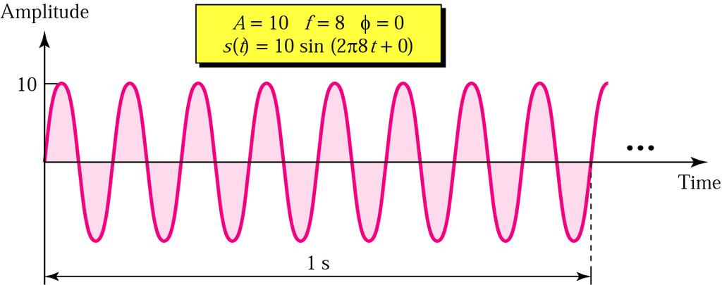
23 Sine Wave Peak Amplitude (A) maximum strength of signal volts Frequency (f) Rate of change of signal Hertz (Hz) or cycles per second Period = time for one repetition (T) T = 1/f Phase ( ) Relative position in time 23

24 Sine wave examples 24
25 Varying Sine Waves 25
26 Wavelength Distance occupied by one cycle Distance between two points of corresponding phase in two consecutive cycles Assuming signal velocity v = vt => f= v 26
27 Frequency Domain Concepts A frequency-domain plot is concerned with only the peak value and the frequency Changes of amplitude during one period are not shown easy to plot and conveys the information we can immediately see the values of the frequency and peak amplitude An analog signal is best represented in the frequency domain. The advantage of the frequency domain is that we can immediately see the values of the frequency and peak amplitude 27
28 Time Domain Concepts Time-domain plot shows changes in signal amplitude with respect to time It is an amplitude-versus-time plot 28
29 Time and Frequency Domain 29
30 Time and Frequency Domain 30
31 Composite Signal A single-frequency sine wave is not useful in data communications; we need to change one or more of its characteristics to make it useful. When we change one or more characteristics of a single-frequency signal, it becomes a composite signal made of many frequencies According to Fourier analysis, any composite signal can be represented as a combination of simple sine waves with different frequencies, phases, and amplitudes. 31
32 Fundamental and Harmonics Fundamental Sine wave is the one that has the lowest frequency and biggest amplitude The harmonics are multiples of the fundamental frequency Time period of total signal is equal to the time period of fundamental frequency All frequencies higher than the fundamental are referred to as harmonics. 32

33 Addition of Frequency Components 33
34 34
35 35
36 36
37 37
38 Spectrum & Bandwidth Spectrum The range of frequencies that a signal spans from minimum to maximum. Absolute bandwidth width of spectrum Effective bandwidth Often just bandwidth DC Component Component of zero frequency With a dc component, average amplitude of signal becomes nonzero. 38
39 Example of Spectrum and Bandwidth Consider an average voice: The average voice has a frequency range of roughly 300 Hz to 3100 Hz. The spectrum would thus be Hz The bandwidth would be 2800 Hz 39

40 Data Rate and Bandwidth The bandwidth is a property of a medium: It is the difference between the highest and the lowest frequencies that the medium can satisfactorily pass. In this course, we use the term bandwidth to refer to the property of a medium or the width of a single spectrum. 40

41 Example Example 3 If a periodic signal is decomposed into five sine waves with frequencies of 100, 300, 500, 700, and 900 Hz, what is the bandwidth? Draw the spectrum, assuming all components have a maximum amplitude of 10 V. Solution B = f h - f l = = 800 Hz The spectrum has only five spikes, at 100, 300, 500, 700, and
42 Example 42
43 Analog Signals Carrying Analog and Digital Data 43
44 Digital Signals Carrying Analog and Digital Data 44
45 A digital signal Bit rate and bit interval 45
46 Digital Signals Digital Signal as Composite Analog Signal Digital Signal Through a Wide-Bandwidth Medium Digital Signal Through a Band-Limited Medium 46
47 Digital vs Analog 47
48 More about Bandwidth A digital signal is a composite signal with an infinite bandwidth. The bit rate and the bandwidth are proportional to each other. The analog bandwidth of a medium is expressed in hertz; the digital bandwidth, in bits per second 48
49 Analog and Digital Data Transmission Data Entities that convey meaning Signals Electric or electromagnetic representations of data Signaling The physical propagation of signals along a suitable medium Transmission Communication of data by propagation and processing of signals 49
50 Analog Transmission May be analog or digital data Attenuated over distance Use amplifiers to boost signal Also amplifies noise Use Band-Pass Channel A band-pass filter is a device that passes frequencies within a certain range and rejects (attenuates) frequencies outside that rang 50
51 Digital Transmission Integrity endangered by noise, attenuation etc. Repeaters used Repeater receives signal Extracts bit pattern Retransmits Attenuation is overcome Noise is not amplified Use Low-Pass Channel low-pass filter is a filter that passes low-frequency signals but attenuates (reduces the amplitude of) signals with frequencies higher than the cutoff frequency 51
52 Advantages of Digital Transmission Digital technology Data integrity Longer distances over lower quality lines Capacity utilization High bandwidth links economical High degree of multiplexing easier with digital techniques Security & Privacy Encryption Integration Can treat analog and digital data similarly 52
53 Transmission Impairments Signal received may differ from signal transmitted Signals travel through transmission media, which are not perfect. The imperfection cause impairment in the signal. Analog Signals- degradation of signal quality Digital Signals - bit errors Most significant Impairments are: Attenuation Delay distortion Noise 53
54 Attenuation Attenuation means loss of energy. When a signal, simple or composite, travels through a medium, it loses some of its energy so that it can overcome the resistance of the medium. 54
55 Decibel The decibel is a measure of relative strength of two signal levels: Where, NdB = 10 log P2/P1 NdB = number of decibels P1 P2 = input power level = output power level Log 10 = logarithm to base 10 55
56 Delay Distortion Distortion means that the signal changes its form or shape. Distortion occurs in a composite signal, made of different frequencies some of those frequency components arrive at destination sooner than others. Only in guided media Equalizing techniques can be used to overcome it. 56
57 Noise Additional signals inserted between transmitter and receiver Several types of noise are exists such as thermal noise, Induced noise, Crosstalk, and Impulse noise 57
58 Thermal Noise Due to thermal agitation of electrons Uniformly distributed 58
59 Induced Noise Induced noise comes from sources such as motors and appliance. These devices act as sending antenna and the transmission medium act as the receiving antenna. 59
60 Cross Talk Crosstalk A signal from one line is picked up by another Occur due to the electrical coupling between near by twisted pair cable or unwanted signals picked by microwave antennas Unwanted coupling between two different signal paths. For example, hearing another conversation while talking on the telephone. Relatively constant and can be reduced with proper measures. 60
61 Cross Talk 61
62 Impulse Noise Impulse Irregular pulses or spikes e.g. External electromagnetic interference Short duration, High amplitude Difficult to remove from an analog signal because it may be hard to distinguish from the original signal. Impulse noise can damage more bits if the bits are closer together (transmitted at a faster rate). 62
63 63
64 Channel Capacity Channel capacity is the maximum rate at which the data can be transmitted over a given communication path, or channel, under given conditions. Data rate In bits per second Rate at which data can be communicated Bandwidth In cycles per second of Hertz Constrained by transmitter and medium 64
65 Nyquist Bandwidth Nyquist states that if the rate of signal transmission is 2B, then a signal with frequencies no greater than B is sufficient to carry the signal rate. Nyquist s formula indicates that all the other things being equal, doubling the bandwidth, doubles the data rate C = 2B log2 M Where, M = number of discrete voltage levels C = capacity of channel B = Bandwidth of the signal 65
66 Shannon Capacity Formula At a given noise level, the higher the data rate, the higher the error rate. The Shannon s result is that the maximum error free channel capacity is: C = B log2 (1+SNR) Where, C = capacity of channel in bits per second B = Bandwidth of the signal in Hertz SNR = Signal to Noise Ratio (SNR)dB = 10 log10 (signal power/noise) High SNR means a high quality signal and low number of required intermediate repeaters As bandwidth increases, SNR decreases because more noise will be admitted to the system. 66


67 Example Example 1 Consider a noiseless channel with a bandwidth of 3000 Hz transmitting a signal with two signal levels. The maximum bit rate can be calculated as Solution Bit Rate = log 2 2 = 6000 bps 67
.")
68 Example Example 2 Consider the same noiseless channel, transmitting a signal with four signal levels (for each level, we send two bits). The maximum bit rate can be calculated as: Solution Bit Rate = 2 x 3000 x log 2 4 = 12,000 bps 68


69 Example Example 3 Consider an extremely noisy channel in which the value of the signal-to-noise ratio is almost zero. In other words, the noise is so strong that the signal is faint. For this channel the capacity is calculated as Solution C = B log 2 (1 + SNR) = B log 2 (1 + 0) = B log 2 (1) = B 0 = 0 69

. The signal-to-noise ratio is usually 3162.")
 = 3000 log 2 (1 + 3162) = 3000 log 2")
70 Example Example 4 We can calculate the theoretical highest bit rate of a regular telephone line. A telephone line normally has a bandwidth of 3000 Hz (300 Hz to 3300 Hz). The signal-to-noise ratio is usually For this channel the capacity is calculated as Solution C = B log 2 (1 + SNR) = 3000 log 2 ( ) = 3000 log 2 (3163) C = = 34,860 bps 70

71 Example Example 5 We have a channel with a 1 MHz bandwidth. The SNR for this channel is 63; what is the appropriate bit rate and signal level? Solution First, we use the Shannon formula to find our upper limit. C = B log 2 (1 + SNR) = 10 6 log 2 (1 + 63) = 10 6 log 2 (64) = 6 Mbps Then we use the Nyquist formula to find the number of signal levels. 4 Mbps = 2 1 MHz log 2 L L = 4 71
Terminology (1) Chapter 3. Terminology (3) Terminology (2) Transmitter Receiver Medium. Data Transmission. Direct link. Point-to-point.
 Chapter 3. Terminology (3) Terminology (2) Transmitter Receiver Medium. Data Transmission. Direct link. Point-to-point.") Terminology (1) Chapter 3 Data Transmission Transmitter Receiver Medium Guided medium e.g. twisted pair, optical fiber Unguided medium e.g. air, water, vacuum Spring 2012 03-1 Spring 2012 03-2 Terminology
Terminology (1) Chapter 3 Data Transmission Transmitter Receiver Medium Guided medium e.g. twisted pair, optical fiber Unguided medium e.g. air, water, vacuum Spring 2012 03-1 Spring 2012 03-2 Terminology
Data Communication. Chapter 3 Data Transmission
 Data Communication Chapter 3 Data Transmission ١ Terminology (1) Transmitter Receiver Medium Guided medium e.g. twisted pair, coaxial cable, optical fiber Unguided medium e.g. air, water, vacuum ٢ Terminology
Terminology (1) Chapter 3. Terminology (3) Terminology (2) Transmitter Receiver Medium. Data Transmission. Simplex. Direct link.
 Chapter 3. Terminology (3) Terminology (2) Transmitter Receiver Medium. Data Transmission. Simplex. Direct link.") Chapter 3 Data Transmission Terminology (1) Transmitter Receiver Medium Guided medium e.g. twisted pair, optical fiber Unguided medium e.g. air, water, vacuum Corneliu Zaharia 2 Corneliu Zaharia Terminology
Chapter 3 Data Transmission Terminology (1) Transmitter Receiver Medium Guided medium e.g. twisted pair, optical fiber Unguided medium e.g. air, water, vacuum Corneliu Zaharia 2 Corneliu Zaharia Terminology
Chapter 3. Data Transmission
 Chapter 3 Data Transmission Reading Materials Data and Computer Communications, William Stallings Terminology (1) Transmitter Receiver Medium Guided medium (e.g. twisted pair, optical fiber) Unguided medium
Part II Data Communications
 Part II Data Communications Chapter 3 Data Transmission Concept & Terminology Signal : Time Domain & Frequency Domain Concepts Signal & Data Analog and Digital Data Transmission Transmission Impairments
Data Communications & Computer Networks
 Data Communications & Computer Networks Chapter 3 Data Transmission Fall 2008 Agenda Terminology and basic concepts Analog and Digital Data Transmission Transmission impairments Channel capacity Home Exercises
Data and Computer Communications Chapter 3 Data Transmission
 Data and Computer Communications Chapter 3 Data Transmission Eighth Edition by William Stallings Transmission Terminology data transmission occurs between a transmitter & receiver via some medium guided
EC 554 Data Communications
 EC 554 Data Communications Mohamed Khedr http://webmail. webmail.aast.edu/~khedraast.edu/~khedr Syllabus Tentatively Week 1 Week 2 Week 3 Week 4 Week 5 Week 6 Week 7 Week 8 Week 9 Week 10 Week 11 Week
COMP211 Physical Layer
 COMP211 Physical Layer Data and Computer Communications 7th edition William Stallings Prentice Hall 2004 Computer Networks 5th edition Andrew S.Tanenbaum, David J.Wetherall Pearson 2011 Material adapted
Data and Computer Communications. Chapter 3 Data Transmission
 Data and Computer Communications Chapter 3 Data Transmission Data Transmission quality of the signal being transmitted The successful transmission of data depends on two factors: characteristics of the
Lecture 3: Data Transmission
 Lecture 3: Data Transmission 1 st semester 1439-2017 1 By: Elham Sunbu OUTLINE Data Transmission DATA RATE LIMITS Transmission Impairments Examples DATA TRANSMISSION The successful transmission of data
Lecture 2 Physical Layer - Data Transmission
 DATA AND COMPUTER COMMUNICATIONS Lecture 2 Physical Layer - Data Transmission Mei Yang Based on Lecture slides by William Stallings 1 DATA TRANSMISSION The successful transmission of data depends on two
Chapter 3 Data Transmission
 Chapter 3 Data Transmission COSC 3213 Instructor: U.T. Nguyen 1 9/27/2007 3:21 PM Terminology (1) Transmitter Receiver Medium Guided medium e.g. twisted pair, optical fiber Unguided medium e.g. air, water,
Introduction to Telecommunications and Computer Engineering Unit 3: Communications Systems & Signals
 Introduction to Telecommunications and Computer Engineering Unit 3: Communications Systems & Signals Syedur Rahman Lecturer, CSE Department North South University syedur.rahman@wolfson.oxon.org Acknowledgements
Data Communications and Networks
 Data Communications and Networks Abdul-Rahman Mahmood http://alphapeeler.sourceforge.net http://pk.linkedin.com/in/armahmood abdulmahmood-sss twitter.com/alphapeeler alphapeeler.sourceforge.net/pubkeys/pkey.htm
College of information Technology Department of Information Networks Telecommunication & Networking I Chapter DATA AND SIGNALS 1 من 42
 3.1 DATA AND SIGNALS 1 من 42 Communication at application, transport, network, or data- link is logical; communication at the physical layer is physical. we have shown only ; host- to- router, router-to-
Chapter 3 Data and Signals 3.1
 Chapter 3 Data and Signals 3.1 Copyright The McGraw-Hill Companies, Inc. Permission required for reproduction or display. Note To be transmitted, data must be transformed to electromagnetic signals. 3.2
Computer Networks. Practice Set I. Dr. Hussein Al-Bahadili
 بسم االله الرحمن الرحيم Computer Networks Practice Set I Dr. Hussein Al-Bahadili (1/11) Q. Circle the right answer. 1. Before data can be transmitted, they must be transformed to. (a) Periodic signals
DATA TRANSMISSION. ermtiong. ermtiong
 DATA TRANSMISSION Analog Transmission Analog signal transmitted without regard to content May be analog or digital data Attenuated over distance Use amplifiers to boost signal Also amplifies noise DATA
CS307 Data Communication
 CS307 Data Communication Course Objectives Build an understanding of the fundamental concepts of data transmission. Familiarize the student with the basics of encoding of analog and digital data Preparing
Review of Lecture 2. Data and Signals - Theoretical Concepts. Review of Lecture 2. Review of Lecture 2. Review of Lecture 2. Review of Lecture 2
 Data and Signals - Theoretical Concepts! What are the major functions of the network access layer? Reference: Chapter 3 - Stallings Chapter 3 - Forouzan Study Guide 3 1 2! What are the major functions
Introduction to Communications Part Two: Physical Layer Ch3: Data & Signals
 Introduction to Communications Part Two: Physical Layer Ch3: Data & Signals Kuang Chiu Huang TCM NCKU Spring/2008 Goals of This Class Through the lecture of fundamental information for data and signals,
Signal Characteristics
 Data Transmission The successful transmission of data depends upon two factors:» The quality of the transmission signal» The characteristics of the transmission medium Some type of transmission medium
The quality of the transmission signal The characteristics of the transmission medium. Some type of transmission medium is required for transmission:
 Data Transmission The successful transmission of data depends upon two factors: The quality of the transmission signal The characteristics of the transmission medium Some type of transmission medium is
DATA COMMUNICATION. Channel and Noise
 DATA COMMUNICATION Channel and Noise So, it means that for sending, Data, we need to know the type of the signal to be used, and its mode and technique through which it will be transferred Pretty Much
Data Transmission. ITS323: Introduction to Data Communications. Sirindhorn International Institute of Technology Thammasat University ITS323
 ITS323: Introduction to Data Communications Sirindhorn International Institute of Technology Thammasat University Prepared by Steven Gordon on 23 May 2012 ITS323Y12S1L03, Steve/Courses/2012/s1/its323/lectures/transmission.tex,
Basic Concepts in Data Transmission
 Basic Concepts in Data Transmission EE450: Introduction to Computer Networks Professor A. Zahid A.Zahid-EE450 1 Data and Signals Data is an entity that convey information Analog Continuous values within
Chapter 3 Data Transmission COSC 3213 Summer 2003
 Chapter 3 Data Transmission COSC 3213 Summer 2003 Courtesy of Prof. Amir Asif Definitions 1. Recall that the lowest layer in OSI is the physical layer. The physical layer deals with the transfer of raw
Chapter 3 Data and Signals
 Chapter 3 Data and Signals 3.2 To be transmitted, data must be transformed to electromagnetic signals. 3-1 ANALOG AND DIGITAL Data can be analog or digital. The term analog data refers to information that
Signals. Periodic vs. Aperiodic. Signals
 Signals 1 Periodic vs. Aperiodic Signals periodic signal completes a pattern within some measurable time frame, called a period (), and then repeats that pattern over subsequent identical periods R s.
E-716-A Mobile Communications Systems. Lecture #2 Basic Concepts of Wireless Transmission (p1) Instructor: Dr. Ahmad El-Banna
 Instructor: Dr. Ahmad El-Banna") October 2014 Ahmad El-Banna Integrated Technical Education Cluster At AlAmeeria E-716-A Mobile Communications Systems Lecture #2 Basic Concepts of Wireless Transmission (p1) Instructor: Dr. Ahmad El-Banna
October 2014 Ahmad El-Banna Integrated Technical Education Cluster At AlAmeeria E-716-A Mobile Communications Systems Lecture #2 Basic Concepts of Wireless Transmission (p1) Instructor: Dr. Ahmad El-Banna
Data Transmission (II)
") Agenda Lecture (02) Data Transmission (II) Analog and digital signals Analog and Digital transmission Transmission impairments Channel capacity Shannon formulas Dr. Ahmed ElShafee 1 Dr. Ahmed ElShafee,
Agenda Lecture (02) Data Transmission (II) Analog and digital signals Analog and Digital transmission Transmission impairments Channel capacity Shannon formulas Dr. Ahmed ElShafee 1 Dr. Ahmed ElShafee,
Contents. Telecom Service Chae Y. Lee. Data Signal Transmission Transmission Impairments Channel Capacity
 Data Transmission Contents Data Signal Transmission Transmission Impairments Channel Capacity 2 Data/Signal/Transmission Data: entities that convey meaning or information Signal: electric or electromagnetic
Chapter 2. Physical Layer
 Chapter 2 Physical Layer Lecture 1 Outline 2.1 Analog and Digital 2.2 Transmission Media 2.3 Digital Modulation and Multiplexing 2.4 Transmission Impairment 2.5 Data-rate Limits 2.6 Performance Physical
Outline / Wireless Networks and Applications Lecture 3: Physical Layer Signals, Modulation, Multiplexing. Cartoon View 1 A Wave of Energy
 Outline 18-452/18-750 Wireless Networks and Applications Lecture 3: Physical Layer Signals, Modulation, Multiplexing Peter Steenkiste Carnegie Mellon University Spring Semester 2017 http://www.cs.cmu.edu/~prs/wirelesss17/
Announcements : Wireless Networks Lecture 3: Physical Layer. Bird s Eye View. Outline. Page 1
 Announcements 18-759: Wireless Networks Lecture 3: Physical Layer Please start to form project teams» Updated project handout is available on the web site Also start to form teams for surveys» Send mail
Lecture (01) Data Transmission (I)
 Data Transmission (I)") Agenda Lecture (01) Data Transmission (I) The objective Transmission terminologies Bandwidth and data rate Dr. Ahmed ElShafee ١ Dr. Ahmed ElShafee, ACU Spring 2016, Data Communication ٢ Dr. Ahmed ElShafee,
Agenda Lecture (01) Data Transmission (I) The objective Transmission terminologies Bandwidth and data rate Dr. Ahmed ElShafee ١ Dr. Ahmed ElShafee, ACU Spring 2016, Data Communication ٢ Dr. Ahmed ElShafee,
Lecture 2: SIGNALS. 1 st semester By: Elham Sunbu
 Lecture 2: SIGNALS 1 st semester 1439-2017 1 By: Elham Sunbu OUTLINE Signals and the classification of signals Sine wave Time and frequency domains Composite signals Signal bandwidth Digital signal Signal
Physical Layer. Networks: Physical Layer 1
 Physical Layer Networks: Physical Layer 1 Physical Layer Part 1 Definitions Nyquist Theorem - noiseless Shannon s Result with noise Analog versus Digital Amplifier versus Repeater Networks: Physical Layer
Course 2: Channels 1 1
 Course 2: Channels 1 1 "You see, wire telegraph is a kind of a very, very long cat. You pull his tail in New York and his head is meowing in Los Angeles. Do you understand this? And radio operates exactly
Digital and Analog Communication (EE-217-F)
") Digital and Analog Communication (EE-217-F) BOOK Text Book: Data Communications, Computer Networks and Open Systems Halsall Fred, (4thediton) 2000, Addison Wesley, Low Price edition Reference Books: Business
Digital and Analog Communication (EE-217-F) BOOK Text Book: Data Communications, Computer Networks and Open Systems Halsall Fred, (4thediton) 2000, Addison Wesley, Low Price edition Reference Books: Business
Lecture 3 Concepts for the Data Communications and Computer Interconnection
 Lecture 3 Concepts for the Data Communications and Computer Interconnection Aim: overview of existing methods and techniques Terms used: -Data entities conveying meaning (of information) -Signals data
Announcement : Wireless Networks Lecture 3: Physical Layer. A Reminder about Prerequisites. Outline. Page 1
 Announcement 18-759: Wireless Networks Lecture 3: Physical Layer Peter Steenkiste Departments of Computer Science and Electrical and Computer Engineering Spring Semester 2010 http://www.cs.cmu.edu/~prs/wirelesss10/
L(f) = = (f) G(f) L2(f) Transmission Impairments: Attenuation (cont.)
 = = (f) G(f) L2(f) Transmission Impairments: Attenuation (cont.)") Transmission Impairments: Attenuation (cont.) how many times the put signal has attenuated relative to the input signal should be in L(f) (f) (f) A A in (f) (f) how many times the put signal has been amplified
Transmission Impairments: Attenuation (cont.) how many times the put signal has attenuated relative to the input signal should be in L(f) (f) (f) A A in (f) (f) how many times the put signal has been amplified
Data Transmission Definition Data Transmission Analog Transmission Digital Transmission
 Data Transmission Definition Data Transmission Data transmission occurs between transmitter (sender) and receiver over some transmission medium. This transfer of data takes place via some form of transmission
Data Concept Analog and Digital Signal Periodic and Non-Periodic Signal Sine Wave Wave length Time and Frequency Domain Composite Signal Bandwidth
 Data Concept Analog and Digital Signal Periodic and Non-Periodic Signal Sine Wave Wave length and Frequency Domain Composite Signal Bandwidth BPS and Bit Length Data is a usable to a person or application.
Chapter Two. Fundamentals of Data and Signals. Data Communications and Computer Networks: A Business User's Approach Seventh Edition
 Chapter Two Fundamentals of Data and Signals Data Communications and Computer Networks: A Business User's Approach Seventh Edition After reading this chapter, you should be able to: Distinguish between
Chapter 3 Digital Transmission Fundamentals
 Chapter 3 Digital Transmission Fundamentals Why Digital Communications? CSE 3213, Winter 2010 Instructor: Foroohar Foroozan A Transmission System Transmitter Receiver Communication channel Transmitter
Information theory II. Fisica dell Energia - a.a. 2017/2018
 Information theory II Fisica dell Energia - a.a. 2017/2018 Transfer of information Communication Communication is the transfer of information from one place to another. This should be done as efficiently
Data com ch#3 (part 2)
") Data com ch#3 (part 2) ENG. IBRAHEEM LUBBAD TRANSMISSION IMPAIRMENT Attenuation a loss of energy db =20log 10 V2 V1 db < 0 db > 0 db = 0 attenuated amplified not changed Decibel numbers can be added or
Data com ch#3 (part 2) ENG. IBRAHEEM LUBBAD TRANSMISSION IMPAIRMENT Attenuation a loss of energy db =20log 10 V2 V1 db < 0 db > 0 db = 0 attenuated amplified not changed Decibel numbers can be added or
Overview. Lecture 3. Terminology. Terminology. Background. Background. Transmission basics. Transmission basics. Two signal types
 Lecture 3 Transmission basics Chapter 3, pages 75-96 Dave Novak School of Business University of Vermont Overview Transmission basics Terminology Signal Channel Electromagnetic spectrum Two signal types
Antennas and Propagation
 Antennas and Propagation Chapter 5 Introduction An antenna is an electrical conductor or system of conductors Transmission - radiates electromagnetic energy into space Reception - collects electromagnetic
Transmission Impairments
 1/13 Transmission Impairments Surasak Sanguanpong nguan@ku.ac.th http://www.cpe.ku.ac.th/~nguan Last updated: 11 July 2000 Transmissions Impairments 1/13 Type of impairments 2/13 Attenuation Delay distortion
Physical Layer: Outline
 18-345: Introduction to Telecommunication Networks Lectures 3: Physical Layer Peter Steenkiste Spring 2015 www.cs.cmu.edu/~prs/nets-ece Physical Layer: Outline Digital networking Modulation Characterization
Qiz 1. 3.discrete time signals can be obtained by a continuous-time signal. a. sampling b. digitizing c.defined d.
 Qiz 1 Q1: 1.A periodic signal has a bandwidth of 20 Hz the highest frequency is 60Hz. what is the lowest frequency. a.20 b.40 c.60 d.30 2. find the value of bandwidth of the following signal S(t)=(1/5)
Antennas and Propagation
 CMPE 477 Wireless and Mobile Networks Lecture 3: Antennas and Propagation Antennas Propagation Modes Line of Sight Transmission Fading in the Mobile Environment Introduction An antenna is an electrical
Modulation. Digital Data Transmission. COMP476 Networked Computer Systems. Analog and Digital Signals. Analog and Digital Examples.
 Digital Data Transmission Modulation Digital data is usually considered a series of binary digits. RS-232-C transmits data as square waves. COMP476 Networked Computer Systems Analog and Digital Signals
two computers. 2- Providing a channel between them for transmitting and receiving the signals through it.
 1. Introduction: Communication is the process of transmitting the messages that carrying information, where the two computers can be communicated with each other if the two conditions are available: 1-
Fundamentals of Data and Signals
 Fundamentals of Data and Signals Chapter 2 Learning Objectives After reading this chapter, you should be able to: Distinguish between data and signals and cite the advantages of digital data and signals
EIE339 Digital Transmission and Switching Systems
 EIE339 Digital Transmission and Switching Systems Lecturer: Dr. W.Y.Tam Office: DE604 Telephone no.: 666-665 email address: enwytam@polyu.edu.hk Continuous Assessment Tests 5% Assignments and quizzes 5%
Chapter 2: Fundamentals of Data and Signals
 Chapter 2: Fundamentals of Data and Signals TRUE/FALSE 1. The terms data and signal mean the same thing. F PTS: 1 REF: 30 2. By convention, the minimum and maximum values of analog data and signals are
In this lecture. System Model Power Penalty Analog transmission Digital transmission
 System Model Power Penalty Analog transmission Digital transmission In this lecture Analog Data Transmission vs. Digital Data Transmission Analog to Digital (A/D) Conversion Digital to Analog (D/A) Conversion
Antennas and Propagation. Chapter 5
 Antennas and Propagation Chapter 5 Introduction An antenna is an electrical conductor or system of conductors Transmission - radiates electromagnetic energy into space Reception - collects electromagnetic
Data Communications and Networks
 Data Communications and Networks Engr. Abdul Rahman Mahmood MS, MCP, QMR(ISO9001:2000) Usman Institute of Technology University Road, Karachi armahmood786@yahoo.com alphasecure@gmail.com alphapeeler.sf.net/pubkeys/pkey.htm
Antennas and Propagation. Chapter 5
 Antennas and Propagation Chapter 5 Introduction An antenna is an electrical conductor or system of conductors Transmission - radiates electromagnetic energy into space Reception - collects electromagnetic
CS311: Data Communication Transmission Impairments and Channel Capacity. Assistant Professor Dept. of CSE IIT Jodhpur
 CS311: Data Communication Transmission Impairments and Channel Capacity Dr. Manas Khatua Assistant Professor Dept. of CSE IIT Jodhpur E-mail: manaskhatua@iitj.ac.in Impairments To send data we have to
Chapter 3 Digital Transmission Fundamentals
 Chapter 3 Digital Transmission Fundamentals Digital Representation of Information Why Digital Communications? Digital Representation of Analog Signals Characterization of Communication Channels Fundamental
2. By convention, the minimum and maximum values of analog data and signals are presented as voltages.
 Chapter 2: Fundamentals of Data and Signals Data Communications and Computer Networks A Business Users Approach 8th Edition White TEST BANK Full clear download (no formatting errors) at: https://testbankreal.com/download/data-communications-computer-networksbusiness-users-approach-8th-edition-white-test-bank/
Ș.l. dr. ing. Lucian-Florentin Bărbulescu
 Ș.l. dr. ing. Lucian-Florentin Bărbulescu 1 Data: entities that convey meaning within a computer system Signals: are the electric or electromagnetic impulses used to encode and transmit data Characteristics
Session2 Antennas and Propagation
 Wireless Communication Presented by Dr. Mahmoud Daneshvar Session2 Antennas and Propagation 1. Introduction Types of Anttenas Free space Propagation 2. Propagation modes 3. Transmission Problems 4. Fading
Antennas and Propagation
 Mobile Networks Module D-1 Antennas and Propagation 1. Introduction 2. Propagation modes 3. Line-of-sight transmission 4. Fading Slides adapted from Stallings, Wireless Communications & Networks, Second
Chapter 3 Digital Transmission Fundamentals
 Chapter 3 Digital Transmission Fundamentals Characterization of Communication Channels Fundamental Limits in Digital Transmission CSE 323, Winter 200 Instructor: Foroohar Foroozan Chapter 3 Digital Transmission
Some key functions implemented in the transmitter are modulation, filtering, encoding, and signal transmitting (to be elaborated)
") 1 An electrical communication system enclosed in the dashed box employs electrical signals to deliver user information voice, audio, video, data from source to destination(s). An input transducer may be
1 An electrical communication system enclosed in the dashed box employs electrical signals to deliver user information voice, audio, video, data from source to destination(s). An input transducer may be
Introduction to LAN/WAN. Physical Layer
 Introduction to LAN/WAN Physical Layer Topics Introduction Theory Transmission Media Purpose of Physical Layer Transport bits between machines How do we send 0's and 1's across a medium? Ans: vary physical
1. What is the bandwidth of a signal that ranges from 40 KHz to 4 MHz? a MHz (4M -40K) b. 36 MHz c. 360 KHz d. 396 KHz
 b. 36 MHz c. 360 KHz d. 396 KHz") Question 1: Choose the correct answer 1. What is the bandwidth of a signal that ranges from 40 KHz to 4 MHz? a. 3.96 MHz (4M -40K) b. 36 MHz c. 360 KHz d. 396 KHz 2. Consider a noiseless channel with a
Question 1: Choose the correct answer 1. What is the bandwidth of a signal that ranges from 40 KHz to 4 MHz? a. 3.96 MHz (4M -40K) b. 36 MHz c. 360 KHz d. 396 KHz 2. Consider a noiseless channel with a
UNIT-1. Basic signal processing operations in digital communication
 UNIT-1 Lecture-1 Basic signal processing operations in digital communication The three basic elements of every communication systems are Transmitter, Receiver and Channel. The Overall purpose of this system
CPSC Network Programming. How do computers really communicate?
 CPSC 360 - Network Programming Data Transmission Michele Weigle Department of Computer Science Clemson University mweigle@cs.clemson.edu February 11, 2005 http://www.cs.clemson.edu/~mweigle/courses/cpsc360
Antennas & Propagation. CSG 250 Fall 2007 Rajmohan Rajaraman
 Antennas & Propagation CSG 250 Fall 2007 Rajmohan Rajaraman Introduction An antenna is an electrical conductor or system of conductors o Transmission - radiates electromagnetic energy into space o Reception
Cable Testing TELECOMMUNICATIONS AND NETWORKING
 Cable Testing TELECOMMUNICATIONS AND NETWORKING Analog Signals 2 Digital Signals Square waves, like sine waves, are periodic. However, square wave graphs do not continuously vary with time. The wave holds
CS441 Mobile & Wireless Computing Communication Basics
 Department of Computer Science Southern Illinois University Carbondale CS441 Mobile & Wireless Computing Communication Basics Dr. Kemal Akkaya E-mail: kemal@cs.siu.edu Kemal Akkaya Mobile & Wireless Computing
Fundamentals of Digital Communication
 Fundamentals of Digital Communication Network Infrastructures A.A. 2017/18 Digital communication system Analog Digital Input Signal Analog/ Digital Low Pass Filter Sampler Quantizer Source Encoder Channel
Lecture 5 Transmission
 Lecture 5 Transmission David Andersen Department of Computer Science Carnegie Mellon University 15-441 Networking, Spring 2005 http://www.cs.cmu.edu/~srini/15-441/s05 1 Physical and Datalink Layers: 3
TE 302 DISCRETE SIGNALS AND SYSTEMS. Chapter 1: INTRODUCTION
 TE 302 DISCRETE SIGNALS AND SYSTEMS Study on the behavior and processing of information bearing functions as they are currently used in human communication and the systems involved. Chapter 1: INTRODUCTION
CHAPTER -15. Communication Systems
 CHAPTER -15 Communication Systems COMMUNICATION Communication is the act of transmission and reception of information. COMMUNICATION SYSTEM: A system comprises of transmitter, communication channel and
COMMUNICATION SYSTEMS -I
 COMMUNICATION SYSTEMS -I Communication : It is the act of transmission of information. ELEMENTS OF A COMMUNICATION SYSTEM TRANSMITTER MEDIUM/CHANNEL: The physical medium that connects transmitter to receiver
EITF25 Internet Techniques and Applications L2: Physical layer. Stefan Höst
 EITF25 Internet Techniques and Applications L2: Physical layer Stefan Höst Data vs signal Data: Static representation of information For storage Signal: Dynamic representation of information For transmission
PRINCIPLES OF COMMUNICATION SYSTEMS. Lecture 1- Introduction Elements, Modulation, Demodulation, Frequency Spectrum
 PRINCIPLES OF COMMUNICATION SYSTEMS Lecture 1- Introduction Elements, Modulation, Demodulation, Frequency Spectrum Topic covered Introduction to subject Elements of Communication system Modulation General
Lecture 5 Transmission. Physical and Datalink Layers: 3 Lectures
 Lecture 5 Transmission Peter Steenkiste School of Computer Science Department of Electrical and Computer Engineering Carnegie Mellon University 15-441 Networking, Spring 2004 http://www.cs.cmu.edu/~prs/15-441
Chapter-1: Introduction
 Chapter-1: Introduction The purpose of a Communication System is to transport an information bearing signal from a source to a user destination via a communication channel. MODEL OF A COMMUNICATION SYSTEM
Chapter 1: Introduction. EET-223: RF Communication Circuits Walter Lara
 Chapter 1: Introduction EET-223: RF Communication Circuits Walter Lara Introduction Electronic communication involves transmission over medium from source to destination Information can contain voice,
1/14. Signal. Surasak Sanguanpong Last updated: 11 July Signal 1/14
 1/14 Signal Surasak Sanguanpong nguan@ku.ac.th http://www.cpe.ku.ac.th/~nguan Last updated: 11 July 2000 Signal 1/14 Transmission structure 2/14 Transmitter/ Receiver Medium Amplifier/ Repeater Medium
Point-to-Point Communications
 Point-to-Point Communications Key Aspects of Communication Voice Mail Tones Alphabet Signals Air Paper Media Language English/Hindi English/Hindi Outline of Point-to-Point Communication 1. Signals basic
Media. Twisted pair db/km at 1MHz 2 km. Coaxial cable 7 db/km at 10 MHz 1 9 km. Optical fibre 0.2 db/km 100 km
 Media Attenuation Repeater spacing Twisted pair 10-12 db/km at 1MHz 2 km Coaxial cable 7 db/km at 10 MHz 1 9 km Optical fibre 0.2 db/km 100 km conniq.com provides an excellent tutorial on physical media.
Hello and welcome to today s lecture. In the last couple of lectures we have discussed about various transmission media.
 Data Communication Prof. Ajit Pal Department of Computer Science & Engineering Indian Institute of Technology, Kharagpur Lecture No # 7 Transmission of Digital Signal-I Hello and welcome to today s lecture.
Last Time. Transferring Information. Today (& Tomorrow (& Tmrw)) Application Layer Example Protocols ftp http Performance.
) Application Layer Example Protocols ftp http Performance.") 15-441 Lecture 5 Last Time Physical Layer & Link Layer Basics Copyright Seth Goldstein, 2008 Application Layer Example Protocols ftp http Performance Application Presentation Session Transport Network
15-441 Lecture 5 Last Time Physical Layer & Link Layer Basics Copyright Seth Goldstein, 2008 Application Layer Example Protocols ftp http Performance Application Presentation Session Transport Network
Chapter-15. Communication systems -1 mark Questions
 Chapter-15 Communication systems -1 mark Questions 1) What are the three main units of a Communication System? 2) What is meant by Bandwidth of transmission? 3) What is a transducer? Give an example. 4)
Jaringan Komputer. Outline. The Physical Layer
 Jaringan Komputer The Physical Layer Outline Defines the mechanical, electrical, and timing interfaces to the network Theoretical analysis of data transmission Kinds of transmission media Examples: the
Communication Engineering Prof. Surendra Prasad Department of Electrical Engineering Indian Institute of Technology, Delhi
 Communication Engineering Prof. Surendra Prasad Department of Electrical Engineering Indian Institute of Technology, Delhi Lecture 1 Introduction to Communication Engineering I will go through a very brief
Unbounded Transmission Media
 Unbounded Transmission Media Unbounded Media The three main types of wireless media are Radio Microwave infrared Electromagnetic spectrum for wireless communication Unguided waves can travel from source
TSEK02: Radio Electronics Lecture 2: Modulation (I) Ted Johansson, EKS, ISY
 Ted Johansson, EKS, ISY") TSEK02: Radio Electronics Lecture 2: Modulation (I) Ted Johansson, EKS, ISY An Overview of Modulation Techniques: chapter 3.1 3.3.1 2 Introduction (3.1) Analog Modulation Amplitude Modulation Phase and
TSEK02: Radio Electronics Lecture 2: Modulation (I) Ted Johansson, EKS, ISY An Overview of Modulation Techniques: chapter 3.1 3.3.1 2 Introduction (3.1) Analog Modulation Amplitude Modulation Phase and