5X Racing Mazda Miata Shifter Rebuild Kit Installation Instructions
|
|
|
- Roxanne Knight
- 5 years ago
- Views:
Transcription
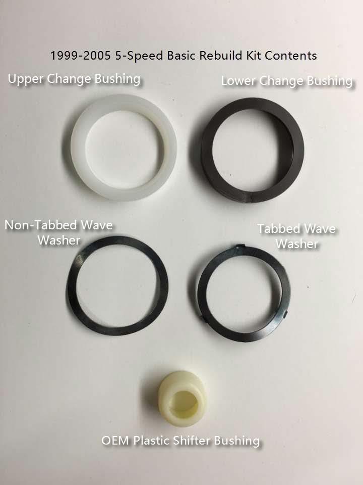
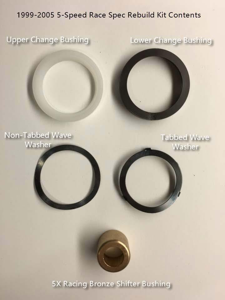
1 5X Racing Mazda Miata Shifter Rebuild Kit Installation Instructions Thank you for purchasing our Miata shifter rebuild kit for the Mazda Miata! These instructions will guide you on how to properly rebuild the shifter assembly in your Miata. DISCLAIMER! These instructions are designed to be used as a guide to help understand the procedure of rebuilding a Miata shifter assembly. 5X Racing nor any of its owners or employees will be held responsible for any damages or injuries incurred to the installer caused by improper installation or accidents which might occur while using any procedure outlined within this guide. Please use caution when working on your car - however simple the task may be and ALWAYS consult with a professional mechanic when you feel uncomfortable with a task presented to you! Tools Needed: 10mm socket and ratchet (1/4 recommended) Phillips head screwdriver Flat head screwdriver (small tip) Razor knife WD-40 spray or equivalent Bulb-Type Fluid Sucker (Turkey Baster) Paper towels Large Vise-Grips Special Information Regarding our Kits: Our kits include all OEM Mazda components - except for our upgraded Bronze shifter bushing if you chose that option - which ensure proper fit and quality. The original components of your Miatas shifter might look different from the components you ll receive in our kit - and perhaps even different than the components pictured within this guide by the time of reading - and here s why: Since the release of the original 1990 Miata, Mazda may have updated the components of the shifter assembly and superseded some of the original parts with newer or revised parts in-between model years. This is normal practice for a manufacturer to do, and especially with cars that are upwards of 20-years old now. In addition to manufacturer supersession, we did the additional research and testing and substituted certain components for our kits to improve them over their original configurations. Here is a brief outline of those changes: o Lower Shift Boot: The most noticeable part we substitute is the lower shifter boot. The Mazda MX-5 uses the same bolt pattern as the Miata, and is a much more affordable and superior option to the original lower boots of the Miatas. We ve tested this boot extensively and can verify that it is an improvement over the original lower boots. o Adjustment Shims: This is covered in detail within the guide, but we found the shims might not be a necessary item in most applications, so we started providing only one shim in our kits and might eventually eliminate them altogether as we prove they re not needed over time. These could have been a correction needed in early models that was fixed in later models, so most cars might not need them making the extra cost unnecessary to the majority of customers. o Bronze Shifter Bushings: Once we started racing, we saw the immediate need for a stronger shifter tip bushing as we were breaking the original plastic bushings during our races. Thus came the creation of our bronze shifter bushings. We offer both the OEM plastic bushing and our bronze bushing as a choice when you purchase our kits, and we of course recommend our bushing over the plastic one to anyone who drives enthusiastically, participates in track events, or simply wants a solid feeling shifter and lifetime bushing.
2
3

4 1. Remove the shift knob by unscrewing it counter-clockwise 2. Remove the center console by locating the 5 screws and removing them. This procedure is outlined in your repair manual and we won t go into depth on it besides these simple steps: a. Remove the two screws on the side of the console in line with the shifter b. Remove the one screw under the ash tray c. There are two screws located inside the floor of the armrest compartment under the flip up lid d. Snap the front of the console up, lift the shifter boot over the shifter threaded end, then slide it forward towards the radio while guiding it over the trunk and fuel door release levers at the rear of the console. Remove and set aside 3. Remove the four 10mm bolts holding the upper shift boot to the chassis a. Pull the boot gently upwards (if it is not being replaced), turning it inside out over the top of the shifter to gain access to the lower shift boot bolts. 4. Remove the three 10mm bolts holding the lower shift boot to the transmission 5. Pull the entire shifter assembly with the boots attached out of the transmission and out of the car. Be careful of dripping transmission oil left over on the bottom of the shifter. Set assembly aside 6. If your OEM plastic shifter bushing is still intact, it will be snapped onto the bottom of the shifter when you remove it from the transmission. If it is NOT there, it is most likely broken and one of two things have happened: a. There are pieces of it located within the shifter turret recess where the bushing is normally located. If this is the case, remove them with needle nose pliers or tweezers b. It has completely disintegrated and has fallen to the bottom of the turret in pieces. No need to try and find them as they ll not interfere with anything
 8.")
5 7. Remove the transmission fluid from the turret area at least low enough to expose the change mechanism where the shifter bushing sits. This can be done with a turkey baster or bulb type sucker, or in a pinch, a bunch of paper towels to absorb the fluid. (6-speed transmissions have no turret fluid) 8. Take your shifter assembly to a work bench and remove the shifter bushing (if still snapped onto the shifter) by knocking it off with a rubber hammer, wooden hammer handle, or with a pair of Channel- Lock pliers. Be careful not to damage the tip of the shifter if using pliers 9. Remove the Upper Shift Boot a. If it is still in good condition: Remove by spraying WD-40 on the shifter shaft and underneath the white collar that clamps the rubber boot to the shifter. Use the flat blade screwdriver to lift the rubber under the collar so the WD-40 can penetrate underneath the collar. Slide the upper shift boot up and over the shaft of the shifter and remove it slowly taking care not to damage the rubber boot that is clamped around the shaft b. If it is damaged and bad: simply cut the white collar with wire cutters or a knife and remove it 10. We need to remove the lower boot to allow removal and reinstallation of the upper wave washer and change bushing that sits on top of the shifter pivot ball, so the lower shift boot will need to be destroyed to be removed, which is why we include them in every kit. We find that using a razor to cut around the base of the lower boot is easiest. Also cut the accordion part of the boot down the middle and remove it along with the lower boot base


6 11. Remove the upper change bushing/wave washer assembly and any shims that might be installed from the assembly, then clean the entire portion of the shifter to remove the oil and WD-40 residue


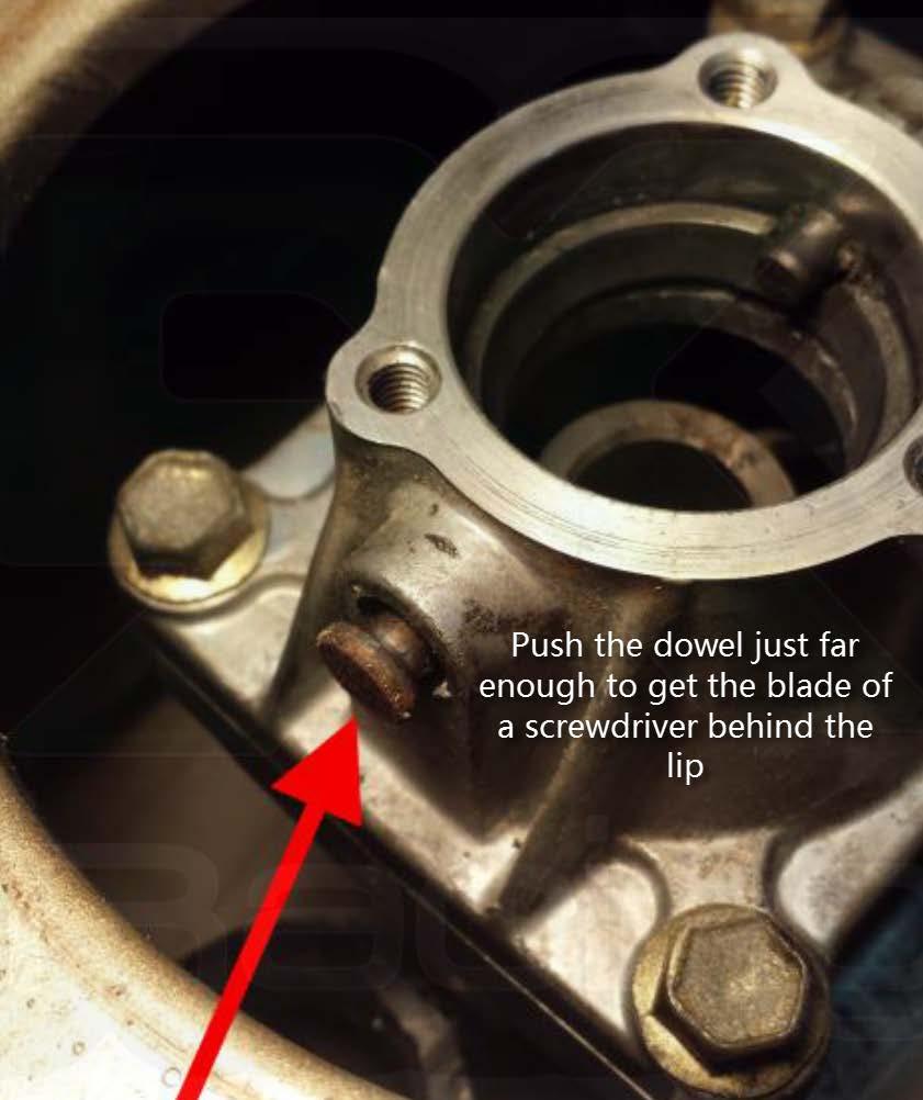
7 12. With the shifter assembly removed, you will now need to remove the lower change bushing (black plastic ring) and wave washer that sit on the ledge inside the shifter turret. There are two locating dowel pins that inhibit the bushing from being removed, so one of those dowels must be pushed back to allow removal. The rearward dowel is the best choice in our opinion: a. Using a large pair of Vise-Grips and a nut or socket that can go over the backside of the dowel pin, press out the rear dowel enough to get a flat blade screwdriver behind the lip
8


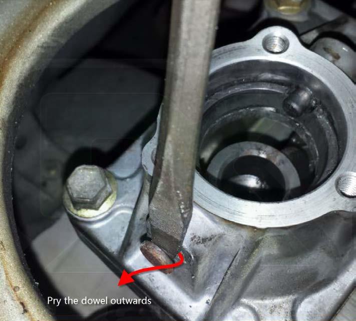
9 b. Pry the dowel outwards enough so that it is flush with the inside wall of the turret c. Lift the black lower change bushing and wave washer underneath it up and out past the dowel you pressed back


10 13. Find the non-tabbed wave washer and slip it onto the shelf in the turret, sliding it underneath the dowel pin first 14. Install lower change bushing on top of the wave washer, making sure the divot in the bushing is underneath the dowel pin. This is a one-way fit, as the bushing will not install if it is not correctly aligned. It should snap down with a little bit of force is applied

 to guard the metal in the turret from bring marred by the")
11 15. You will now need to press the dowel pin back into the turret. Simply reverse the procedure of pressing it out, but without the nut. We recommend using a piece of rubber (we used the one from the lower shift boot we cut or a piece of coolant/fuel hose) to guard the metal in the turret from bring marred by the jaw of the Vice-Grips. Press it until it is flush


12 16. Take the 5X Racing Bronze Shifter Bushing and install it within the shifter bushing cup at the bottom of the turret. The best way to do this is to put the bushing on your fingertip and point it into the cup, then wiggle your finger back and forth to free the bushing. It should settle flush into the cup, with the top of the bushing even with the bottom of the bevel on the top of the bushing cup a. If you purchased the OEM shifter (basic) option, install the OEM plastic shifter bushing onto the tip of the shifter at this time. Simply place the bushing open side up on a bench, place the tip of the shifter (small ball) on top of the shifter bushing and push it into the bushing. It should snap in. If you cannot push it in, you can give the top of the shifter a tap to snap it in


13 17. Refill the turret with transmission fluid. It should take less than a half a quart, or just enough to cover the mechanism where the shifter bushing cup is located, ensuring the shifter bushing is lubricated. Any transmission fluid can be used as it is not lubricating gears and won t see the shearing forces that the fluid in the gearbox will see, so it s not as important what brand you use 18. Reinstall the shifter assembly into the transmission


14 19. Take the tabbed wave washer and snap it onto the upper change bushing 20. Slide the upper change bushing/wave washer assembly over and onto the shifter and into the groove around the pivot ball in the turret, ensuring the wave washer is on top. It might be a tight fit going over the flare in the shifter shaft, but it is designed to go over it


15 21. Find the lower shift boot, spray WD-40 liberally to the interior of the accordion part of the boot, and slide it base side down over the shifter. The top of the accordion should snap into place just below the thick part of the shifter and settle into the smaller portion below it a. Rotate the boot on the shifter until the bolt holes line up. The orientation of the boot does not matter b. Find the three 10mm bolts and tighten them carefully. The metal in the turret is soft and they could easily strip if you use too much pressure. We recommend a ¼ ratchet and 10mm socket for this


16 22. Reinstall the upper shift boot in the same manner as the lower boot by spraying WD-40 in and around the inner portion of the hole in the boot. Slide the boot over the shifter with the narrow end of the base pointing towards the rear of the car and aligned with the bolt holes in the transmission tunnel. a. Press the collar down until you feel it catch on the flared bottom of the shifter shaft. Pressing down too far will cause the boot lip to snap down to where the lower boot lip is and it s hard to get back up 23. Install the four 10mm gold bolts for the upper shift boot. These can be made tight, they won t strip 24. Reinstall your center console in the reverse order you removed it 25. Reinstall your shift knob


17 This completes the installation of your 5X Racing Shifter Rebuild kit! We re sure you are going to love the feel of your rehabilitated shifter, especially if you ve upgraded to our bronze bushing! If you have any questions or feedback in regards to our kit or the process outlined in these instructions, please us at or submit an inquiry through the Contact Us page of our website Thanks again, and enjoy! 5X Racing Team
5X Racing Miata Radio Delete Plate Installation Instructions
 5X Racing 99-05 Miata Radio Delete Plate Installation Instructions Thank you for purchasing our unique, aluminum race inspired radio delete plate for your 1999-2005 Mazda Miata! These instructions will
Suggested Instructions for: , , , C5 Emergency Brake Boot
 Suggested Instructions for: 608-348, 608-349, 614-653, 619-200 C5 Emergency Brake Boot Tools Ratchet, 10mm socket, extension #15 Torx screwdriver Needle nose pliers Masking Tape Very small flat head screwdriver
C70 Window Roller Repair Taken from: Heres the problem:
 C70 Window Roller Repair Taken from: http://www.volvospeed.com/vs_forum/topic/115086-how-to-c70-window-rollers-permanent-fix/ Heres the problem: This happened to two separate window assemblys on my c70
Installation Instructions Precision Sport Shifter
 Installation Instructions Precision Sport Shifter 2004 and up Pontiac GTO Part Number 45043 2010, 2005, 2004 by B&M Racing and Performance Products This B&M Precision Sport Shifter has been designed to
INSTALL/REMOVAL INSTRUCTIONS: WINDOW REGULATOR
 REMOVAL/INSTALL OF WINDOW REGULATOR (741-584) Ford Focus 2000-2007 General Tech Tips: Use painter s tape rather than duct tape to secure window. It will not damage paint or leave sticky residue. A plastic
RACER TECH COMMANDER HD TIE ROD INSTALLATION
 RACER TECH COMMANDER HD TIE ROD INSTALLATION NOTE: These instructions are a universal explanation of how to install our HD Tie Rods. All kits are identical for all inner joints and nearly identical for
TRUE TECHNICAL SERVICE MANUAL - ALL MODELS. DOORS/DRAWERS/LIDS
 DOORS/DRAWERS/LIDS 55 56 NOTES DOORS/DRAWERS/LIDS Swing s 73 74 NOTES INSTALLATION OF A GDM-SWING DOOR Phillips Head Screwdriver (2) - 1/8" Drift Punches (forged) Top Bracket NOTE: It may be necessary
7878 K940. Checkpoint Antenna. Kit Instructions. Issue B
 7878 K940 Checkpoint Antenna Kit Instructions Issue B Revision Record Issue Date Remarks A July 7, 2009 First issue B Nov2013 Revised the Checkpoint installation procedures for 7878 and 7874 scanners Added
Replacing the Reciprocator on an SWF Multi-head.
 Replacing the Reciprocator on an SWF Multi-head. Follow the instructions below to replace the reciprocator in the SWF multi-head machines. The tools required are found in the tool kit that came with the
Cut-True 16M Manual Paper Cutter
 Cut-True 16M Manual Paper Cutter 2/2013 OPERATOR MANUAL FIRST EDITION TABLE OF CONTENTS TOPIC PAGE Specifications 1 Safety Guidelines 1 Assembly 2 Overview 3 Description of Equipment Parts 3-4 Operation
Fig Remove chain cover plate bolts. Fig Remove hammer member. Fig Loosen set screws at base of 12-tooth sprocket.
 Fig. 17.2. Remove chain cover plate bolts. Fig. 17.1. Remove hammer member. Fig. 17.3. Remove chain cover plate. Fig. 17.4. Loosen set screws at base of 12-tooth sprocket. Page 61 Fig. 17.5. Remove socket
Maintenance Information
 16601023 Edition 2 January 2014 Air Impact Wrench 2705P1 Maintenance Information Save These Instructions Product Safety Information WARNING Failure to observe the following warnings, and to avoid these
ELECTRIC TOOL CORPORATION
 Cat. No. -0 / Hex Demolition Hammer Cat. No. 0-0 Spline Rotary Hammer MILWAUKEE ELECTRIC TOOL CORPORATION W. LISBON ROAD BROOKFIELD, WISCONSIN 00-0 -9-00 d 000 -9-00 d SpecialTools Require Forcing discs
Finish Line Emergency Brake Boot INSTRUCTION SHEET. Part Number. Application: Corvette. Part Includes.
 Application: 1997-2004 Corvette Part Includes 1 - Emergency Brake Boot Finish Line Emergency Brake Boot Tools Needed T15 10mm PRE-INSTALLATION NOTES Read completely through instructions to familiarize
Bushwacker Jeep Flat Style Fender Flares Front Pair
 Bushwacker Jeep Flat Style Fender Flares Front Pair Note: These instructions involve cutting parts of your vehicle. Please read all instructions prior to starting. Installation Time: 3-4 Hours Tools Required:
Installation Instructions for FC2 & FC15 Forward Controls for the Super Magna
 Installation Instructions for FC2 & FC15 Forward Controls for the Super Magna It is highly recommended that you use a thread lock compound such as Loctite brand on all threads to keep them from vibrating
Midwest RDH Handpiece Repair Procedure
 Midwest RDH Handpiece Repair Procedure The Midwest RDH handpiece is fairly common and is used by hygienists to clean teeth. The most common problems for this handpiece include a bad prophy head or a dirty
REPAIR INSTRUCTIONS. Cat. No Cat. No MILWAUKEE ELECTRIC TOOL CORPORATION. SDS Max Demolition Hammer. SDS Max Rotary Hammer
 Cat. No. 9-0 SDS Max Demolition Hammer Cat. No. -0 SDS Max Rotary Hammer MILWAUKEE ELECTRIC TOOL CORPORATION W. LISBON ROAD BROOKFIELD, WISCONSIN 00-0 8-9-0 d 000 8-9-0 d Special Tools Require Forcing
Bushwacker Jeep Flat Style Fender Flares Rear Pair (JK Wrangler 2dr)
") Bushwacker Jeep Flat Style Fender Flares Rear Pair (JK Wrangler 2dr) Note: These instructions involve cutting parts of your vehicle. Please read all instructions prior to starting. Installation Time: 3-4
Bushwacker Jeep Flat Style Fender Flares Rear Pair (JK Wrangler 2dr) Note: These instructions involve cutting parts of your vehicle. Please read all instructions prior to starting. Installation Time: 3-4
Service Bulletin
 Service Bulletin 18-026 April 24, 2018 Version 5 Safety Recall: Left (Driver Side) Second Row Seat Recliner Does Not Lock Supersedes 18-026, dated April 7, 2018 to revise the information highlighted in
Replacing the Reciprocator on the SWF Compact Series Machine (601C and 1201C)
") Follow the instructions below to replace the reciprocator in the SWF Compact series machines. The tools required can be found in the tool kit that came with the machine. Preparation 1. First, place the
Follow the instructions below to replace the reciprocator in the SWF Compact series machines. The tools required can be found in the tool kit that came with the machine. Preparation 1. First, place the
RZ 200 Parts Diagram. To avoid confusion during installation remove this page and router being installed pages, return others to box.
 Collar Page 1 To avoid confusion during installation remove this page and router being installed pages, return others to box. Caution: Before and during installation of Router Raizer make sure power switch
MMD Convertible Styling Bar Customer Installation Guide
 MMD Convertible Styling Bar Customer Installation Guide TOOLS REQUIRED/RECOMMENDED: Electric Drill 1 Forstner Bit (Hole Saw) 1 3/8 Hole Saw (manual calls for 1 ¾ ) 1/8, 3/8 & ¾ Drill Bits Rivet Gun Trim
Clocking a TD-04 Turbo Compressor Housing. Appendix A : AWIC Silicone and Tubing Fitting
 Clocking a TD-04 Turbo Compressor Housing Appendix A : AWIC Silicone and Tubing Fitting Revision A: 7-13-2015 Tools: Metric Sockets (10, 12, 14, 17mm) 5mm Hex Key Large Internal Snap Ring Pliers 3/8 Socket
Giraud Tool Company, Inc.
 Motor Upgrade for Gracey Trimmer This package is intended to allow the user to upgrade their Gracey trimmer with a higher rpm motor and convenience features not found in the production offering. This upgrade
AR-15 Lower Receiver Assembly Instructions
 AR-15 Lower Receiver Assembly Instructions Tools There are a few tools that make it easier to put together these kits, but none of them are necessary. Minimum requirements include a hammer and punch to
Repairing Microsoft Wedge Touch Mouse Battery Cover Retaining Clip
 Repairing Microsoft Wedge Touch Mouse Battery Cover Retaining Clip Disassembly, repair and reassembly of Wedge Touch mouse when the battery cover will not stay closed. Also is a good guide to repair other
AUDI A8 D3 REPLACING THE OUTSIDE DRIVER DOOR HANDLE
 AUDI A8 D3 REPLACING THE OUTSIDE DRIVER DOOR HANDLE The keyless entry system in the D3 is a great feature. If you have the car key fob in your pocket, putting your hand under the door handle will unlock
1. Turn off or disconnect power to unit (machine). 2. Push IN the release bar on the quick change base plate. Locking latch will pivot downward.
. 2. Push IN the release bar on the quick change base plate. Locking latch will pivot downward.") Figure 1 Miniature Quick Change Applicators, of the end feed type, are designed to crimp end feed strip terminals to prestripped wires. Each applicator is set up to accept the strip form of certain specific
Figure 1 Miniature Quick Change Applicators, of the end feed type, are designed to crimp end feed strip terminals to prestripped wires. Each applicator is set up to accept the strip form of certain specific
The Useless Machine. DIY Soldering Edition. Instruction Guide v0004
 The Useless Machine DIY Soldering Edition Instruction Guide v0004 TM For the best outcome, follow each step in order. We recommend reading this guide entirely before you get started. Tools required: Soldering
1104. Clean up the door striker plates with a hand grinder using a wire brush and WD-40.
 Chapter 31 - Misc. Putting VW Back Together (Video Clip 31) 1104. Clean up the door striker plates with a hand grinder using a wire brush and WD-40. 1105. Install both door striker plates on the VW body
Installation Guide for Rough Country 1.25 inch Body Lift Kit w/o Shocks (07-15 Wrangler JK 4 Door) Item # J10048 Option B; Manual
 Item # J10048 Option B; Manual") Installation Guide for Rough Country 1.25 inch Body Lift Kit w/o Shocks (07-15 Wrangler JK 4 Door) Item # J10048 Option B; Manual Installation Time: 3 Hours Tools Required: Jack (Tall enough to reach body
Installation Guide for Rough Country 1.25 inch Body Lift Kit w/o Shocks (07-15 Wrangler JK 4 Door) Item # J10048 Option B; Manual Installation Time: 3 Hours Tools Required: Jack (Tall enough to reach body
Quick Fit Installation Guide Retractable Screen - Single Door
 Quick Fit Installation Guide Retractable Screen - Single Door 1 REMOVE KIT PARTS FROM SHIPPING TUBE 15 Mounting screws 1 Housing end cap screw 2 Handles 1 Housing end cap 1 Bushing 1 Pull bar end cap 2
STEINBERGER TRANSTREM (TYPE 2) TECHNICAL DOCUMENT
 TECHNICAL DOCUMENT") STEINBERGER TRANSTREM (TYPE 2) TECHNICAL DOCUMENT These instructions apply to newer style TransTrems only (non-threaded ball type or modified threaded ball type). For purposes of discussion, these TransTrems
STEINBERGER TRANSTREM (TYPE 2) TECHNICAL DOCUMENT These instructions apply to newer style TransTrems only (non-threaded ball type or modified threaded ball type). For purposes of discussion, these TransTrems
Quick Fit Installation Guide Retractable Screen - Double Door
 Quick Fit Installation Guide Retractable Screen - Double Door 1 REMOVE KIT PARTS FROM SHIPPING TUBE 2 Slide bolts 2 Rail receiver Clips 15 Mounting screws 1 Housing end cap screw 2 Handles 1 Housing end
2. Stand mainframe upright and cut bungee cord tie strap.
 2 3 1. Remove the seat rail from the main frame by first removing vertical frame tensioning bolt and the lower seat rail to main frame bolt as shown. Remove the entire seat rail/footplate assembly from
It is highly recommended that you use a thread lock compound such as Loctite brand on all threads to keep them from vibrating loose.
 Installation instructions for FC12 Forward Controls for Kawasaki Vulcan 750 It is highly recommended that you use a thread lock compound such as Loctite brand on all threads to keep them from vibrating
FACTORY CAT TOMCAT CORPORATION
 FACTORY CAT RPS TOMCAT CORPORATION Artificial Turf and Carpet Sweeping Install Kit #349-641 & #349-642 1. Detach batteries so that there is no power running through the machine before starting. 2. Start
HDL(M)6 Nut/Screw Assembly
6 Nut/Screw Assembly") HDL(M)6 Nut/Screw Assembly Remove, repair, and reassemble the nut and screw assembly in your HDL series double lock vise. In these instructions when we refer to the front of the vise or nut/screw assembly,
HDL(M)6 Nut/Screw Assembly Remove, repair, and reassemble the nut and screw assembly in your HDL series double lock vise. In these instructions when we refer to the front of the vise or nut/screw assembly,
Zenith Stromberg Carburettor Repair Guide
 Zenith Stromberg Carburettor Repair Guide Among the greatest mysteries about Zenith Stromberg carburettors is exactly: where does the dashpot oil go? Usually, the reason is a rotten, leaky O-ring in the
Harmony Remote Repair
 Harmony Remote Repair harmonyremoterepair.com How to install your new Harmony One Front Cover/Touch Screen Important! Before you begin working on your Harmony One, you must discharge any static electricity
3.2.3 Rear Door Window and Quarter Window Carrier Assembly
 Tighten all bolts. Tighten bolts marked -1- and -2- in specified sequence. Tightening torque: 8 Nm Remaining bolts can be tightened in any sequence. Insert door window -3- through window recess without
Race Splitter Upgrade Kit Installation Instructions
 Race Splitter Upgrade Kit Installation Instructions Eric Hazen Rev. 1 Overview: Detailed instructions on installing the FT86 Speed Factory Race Splitter Upgrade Kit on a BRZ; FR-S grills are different
Removing Right-Side. Components. Right-Side. Components. Click Here to Go Back AT THIS POINT
 Click Here to Go Back NOTE: There is an oil passage beneath the driven gear/drive gear assembly. This passage should be plugged prior to removing the driven gear and drive gear. Failure to do so could
MOTOR & BULK HEAD. A Manual for Repair and Maintenance Technicians
 MOTOR & BULK HEAD A Manual for Repair and Maintenance Technicians CAUTION This manual is designed to help technicians who are already experienced in workshop procedures and know how to handle tools. Only
Signal Mirror Installation Instructions Toyota Tacoma
 Signal Mirror Installation Instructions 2005-2015 Toyota Tacoma THE safety accessory of the 21 st Century. P/N 210-0115-0 Rev. A4 (3/11/15), BTV 2005 Muth Mirror Systems, LLC Page 3 of 12PplPage 3 of 12
Removing and Replacing the Y-truck
 Service Documentation Removing and Replacing the Y-truck To remove and replace the Y-truck you will need the following tools: 4mm Allen wrench 12mm stamped flat wrench #2 Phillips screwdriver (magnetic
1. Begin by rolling your window up all the way 2. Remove your door and window handles by unscrewing the flat head set screws behind each handle.
 1. Begin by rolling your window up all the way 2. Remove your door and window handles by unscrewing the flat head set screws behind each handle. 3. Remove the 12 screws that attach the steel interior door
Laminate Cabinet Installation Instructions
 Laminate Cabinet Installation Instructions www.easygaragestorage.com/installation How To Use These Instructions Thank you for your purchase! Please read each step of this manual thoroughly to ensure proper
Astro-Physics Inc. 400QMD Lubrication/Maintenance Guide
 Astro-Physics Inc. 400QMD Lubrication/Maintenance Guide The following guidelines should be followed to lubricate the three main parts of the 400QMD mount. The QMD stands for Quartz Micro-Drive controller.
OPERATION AND MAINTENANCE FOR MODEL MRV050A REVERSIBLE
 OPERATION AND MAINTENANCE FOR MODEL MRV050A REVERSIBLE MANUAL AIR MOTOR 04666770 Edition 1 April, 1999 IMPORTANT SAFETY INFORMATION ENCLOSED. READ THIS MANUAL BEFORE OPERATING TOOL. FAILURE TO OBSERVE
- INSTALLATION INSTRUCTIONS -
 . Supercharger Shaft Upgrade Kit PART# - RY17040-UK-6S5-2 APPLICATION(S): Yamaha FX-SHO, FZR & FZS Required tools Part# IN LB Electronic Torque Wrench N/A T-30 Torx Bit Socket N/A 3mm Allen Wrench N/A
101B, 210X, ELM, VSTB Installation Manual
 101B, 210X, ELM, VSTB Installation Manual 99-16105-I001 Copyright 2010 by ALL rights reserved. Information in this document is subject to change without notice. Companies, names and data used in examples
** Do Not Contact the Store ** For Assistance, including missing or broken parts, Call Customer Service at:
 3/01/2007 VISIT THE LITIME WEB SITE: WWW.LITIME.COM ** Do Not Contact the Store ** For Assistance, including missing or broken parts, Call Customer Service at: 1 (800) 225-3865 Double Shed Doors for Back
KN-8828B Upgrade Directions
 KN-8828B Upgrade Directions This document outlines the steps to take to update earlier Hottop Bean Roasters to the KN-8828B 2007 by Chang Yue and Hottop USA - All Rights Reserved No part of this document
Installation Instructions
 Instructions Created by an: Suzuki Samurai, Sidekick, X90 Geo Tracker Off Road Universal Joint (SKU# SAX-UJOR) Instructions also apply to: SKU# SAX-UJOE, SDT-FY-9095, SAX-SY, STM-SL Installation Instructions
ABM International, Inc.
 ABM International, Inc. Lightning Stitch required 1 1.0: Parts List head and motor assembly (Qty. 1) Reel stand (Qty. 1) Needle bar frame clamp (Qty. 1) Motor drive (Qty. 1) 2 Cable harness with bracket
Mechanical Frappe Press
 Mechanical Frappe Press Operation Manual CONTENTS OPERATIONAL INSTRUCTIONS PRECAUTIONS PART NAMES INCLUDED ITEMS BASIC OPERATION MAINTENANCE REPLACEMENT PARTS Thank you for using The Frapptastic Five Mechanical
INSTALLATION INSTRUCTIONS
 INSTALLATION INSTRUCTIONS TM X-10 Type 1F HIGH SECURITY ELECTRONIC LOCK Table of Contents Introduction... 1 Basic Tools and Materials Needed... 1 Lock Parts for Installation... 1 Installation Kit Contents...
SUPER PRO GUN & SUPER PRO GUN II
 MAGNUM VENUS PRODUCTS Maintenance & Repair Manual Part No. M6707-1-1 Revision 04.14.01 Maintenance & Repair Corporate HQ & Mfg. Phone: (727) 573-2955 Fax: (727) 571-3636 Email: info@magind.com Web: www.magind.com
Model: SCD430 SCD640. Installation & Operation Guide P/N SCD640-95
 Model: SCD430 SCD640 Installation & Operation Guide P/N SCD640-95 Model SCD430 and SCD640 Kurt has two Self-Centering vises, a four-inch jaw width (SCD430) and a six-inch jaw width (SCD640). Jaw opening
INSTALL/REMOVAL INSTRUCTIONS: WINDOW REGULATOR
 REMOVAL/INSTALL OF WINDOW REGULATOR (740-666) Lincoln Town Car 1990 94 General Tech Tips: Use painter s tape rather than duct tape to secure window. It will not damage paint or leave sticky residue. A
HURST COMP STICK KIT DODGE CHARGER, MAGNUM, AND CHRYSLER 300 (with AUTO-STICK) Catalog # & by Hurst Performance
 Catalog # & by Hurst Performance") HURST COMP STICK KIT 2005-2007 DODGE CHARGER, MAGNUM, AND CHRYSLER 300 (with AUTO-STICK) Catalog #538 0410 & 538 0411 2009 by Hurst Performance FORM 159 0410 03/09 Thank you for purchasing the Hurst Comp
HURST COMP STICK KIT 2005-2007 DODGE CHARGER, MAGNUM, AND CHRYSLER 300 (with AUTO-STICK) Catalog #538 0410 & 538 0411 2009 by Hurst Performance FORM 159 0410 03/09 Thank you for purchasing the Hurst Comp
TorqueMaster Replacement Spring
 TorqueMaster Replacement Spring Installation Instructions NOTE: Use these installation instructions in conjunction with the TorqueMaster Repair / Replacement Spring Program literature. Copyright 999 Wayne-Dalton
PROFESSIONAL FLARING TOOL 001ERL 37 & ERL 37
 PROFESSIONAL FLARING TOOL 001ERL 37 & 45 002ERL 37 001ERL shown here OWNER S MANUAL 199R11215 EDUCATIONAL TIPS Make sure the end of the tube is cut off square. Before flaring, make sure the die clamp is
To install new top weight plate bushings in G7 strength units.
 1/5 PURPOSE To install new top weight plate bushings in G7 strength units. RE-WORK PARTS REQUIRED - ZMS4000424 Top Weight Plate Bushing (Quantity 4 per machine). - Matrix Top Weight Plate Bushing Removal
Exterior Door Handle - LH - Unpainted (05-14 All)
") Tools Required: Exterior Door Handle - LH - Unpainted (05-14 All) 1) 10mm and 7mm sockets 2) Socket wrench (small size recommended) 3) T30 Torx bit 4) Plastic pry/molding tool (below, A) 5) Thin plastic
Tools Required: Exterior Door Handle - LH - Unpainted (05-14 All) 1) 10mm and 7mm sockets 2) Socket wrench (small size recommended) 3) T30 Torx bit 4) Plastic pry/molding tool (below, A) 5) Thin plastic
MANUAL PLASTIC STRAPPING TOOL MODEL P404
 OPERATION MANUAL / SPARE PARTS LIST MANUAL PLASTIC STRAPPING TOOL MODEL P404 43.0404.02 43040402.en/MAS/ 12.05 INDEX PAGE 1 SAFETY INSTRUCTIONS 2 2 TECHNICAL DATA 3 3 OPERATION ELEMENTS 4 4 ADJUSTMENT
SERVICE PARTS LIST PAGE 1 OF 6 BASE ASSEMBLY SPECIFY CATALOG NO. AND SERIAL NO. WHEN ORDERING PARTS 12" DUAL BEVEL COMPOUND MITER SAW B27B
 PAGE 1 OF 6 BASE ASSEMBLY 00 0 EXAMPLE: Component Parts (Small #) Are Included When Ordering The Assembly (Large #). SPECIFY CATALOG NO. AND NO. WHEN ORDERING PARTS = Part number change from previous service
For installation assistance, contact SARGENT at DOORS SHOWN HERE SWING IN FOR ILLUSTRATION PURPOSES ONLY.
 SARGENT Installation Instructions for LP8600 x LR8600 & 12-LP8600 x 12-LR8600 Series Low Profile Panic and Fire Exit Devices on Double Egress & Double Doors or LS8600 & 12-LS8600 Low Profile Exit Device
Removal of Interior Door Trim. Ferrari 348 GTS '94 Euro Model LHD
 Removal of Interior Door Trim Ferrari 348 GTS '94 Euro Model LHD Tools required - Small Philips head screwdriver (preferably fairly short for access to the front door trim screw) - Medium Philips head
DYNATRAC BALL JOINT REBUILD INSTRUCTIONS V4.0
 DYNATRAC PRODUCTS 2007-2016 4X4 JEEP JK HEAVY DUTY BALL JOINT JP44-2X3050-C DYNATRAC BALL JOINT REBUILD INSTRUCTIONS V4.0 WARNING: Improper use or installation of this product can cause major failures
TRUE TECHNICAL SERVICE MANUAL - ALL MODELS. DOORS/DRAWERS/LIDS
 DOORS/DRAWERS/LIDS 55 56 NOTES DOORS/DRAWERS/LIDS Springs 97 TORSION SPRING REPLACEMENT GDM RADIUS FRONT - SWING DOOR INSTALLATION INSTRUCTIONS Tools Required (2) - 1 8" drift Punch (forged) Needle-Nose
Motorized M3 AX7200 Rotary-Style Gasket Cutter Operating Instructions
 Motorized M3 AX7200 Rotary-Style Gasket Cutter Operating Instructions INTRODUCTION Congratulations! You are the owner of the finest rotary-style gasket cutter in the world. Originally developed and patented
Bi-Color Signal Mirror Installation Instructions
 Bi-Color Signal Mirror Installation Instructions 2005-2009 Toyota Tacoma THE safety accessory of the 21 st Century. P/N 210-0141-0 Rev. A2 (3/30/09), BTV 2007 Muth Mirror Systems, LLC Page 3 of 13PplPage
Chin Strap, Sealed Pull Pins and Swing Catch for Fiberglass Helmets. Contents
 Chin Strap Chin Strap, Sealed Pull Pins and Swing Catch for Fiberglass Helmets Contents BTM-1 1.1 Chin Strap BTM-4 1.2.3.1 Preparation BTM-1 1.1.1 Chin Strap Removal BTM-4 1.2.3.2 Disassembly BTM-1 BTM-2
SERIES I MILLING MACHINES
 INSTALLATION, OPERATION, MAINTENANCE, AND PARTS LIST SERIES I MILLING MACHINES TP5260 Revised: August 29, 2005 Manual No. M-450 Litho in U.S.A. Part No. M -0009500-0450 June, 2003 MAINTENANCE PROCEDURES
The Useless Machine. Parts Only - Build Guide v0001
 TM The Useless Machine Parts Only - Build Guide v0001 For the best outcome, follow each step in order. We recommend reading this guide entirely before you get started. Tools required: One phillips screwdriver,
JARVIS. Model Brisket Scissor EQUIPMENT... TABLE OF
 Model 423-17 Brisket Scissor EQUIPMENT SELECTION... Ordering No. TABLE OF CONTENTS... Page Model 423--17... 4037003 Air Filter / Regulator / Lubricator 3022003 Air Hose Assembly... 3059018 Balancer...
PROSTEER BALL JOINT REBUILD INSTRUCTIONS V1.0
 DYNATRAC PRODUCTS 2003-2010 4X4 DODGE 2500/3500 HEAVY DUTY BALL JOINT PROSTEER BALL JOINT REBUILD INSTRUCTIONS V1.0 WARNING: Improper use or installation of this product can cause major failures that could
SCION FR-S REAR SPOILER Preparation
 Preparation Part Number: PT938-18130-XX Kit Contents Item # Quantity Reqd. Description 1 1 Spoiler 2 2 Strut 3 1 Hardware Bag Hardware Bag Contents Item # Quantity Reqd. Description 1 2 M6 x 1 Nut with
Thank you for considering "cutting edge technology."
 Thank you for considering "cutting edge technology." Most woodworkers know that a shear cut is far better than a straight cut. They also know that a staggered cut is much better than just a single straight
B B B
 Stock with Scorpion Recoil Pad B..0.0 B..0.0 B..0.0 Removable/Adjustable Tactical Cheekrests X Scorpion Recoil Pad Dual Sided QD Attachment Point Six Position Adjustable Stock Slim Line Rear Aluminum Receiver
Click Here to Go Back
 Click Here to Go Back Fig. -94 Fig. -97 CC42D 10. Remove the cap screw securing the gear shift stopper plate pin retainer; then remove the retainer. Fig. -95 CC45D 12. Remove the link arm and account for
LEGENDS RETRACTABLE DOOR SCREENS
 LEGENDS RETRACTABLE DOOR SCREENS MAGNETIC LATCHING DESIGN SYSTEM 42 I N S T A L L A T I O N I N S T R U C T I O N S 1 MOUNTING OPTIONS Recess : Mount the Screen Cassette using Recess Mounting Clips Recess
Frameless Inline Door With Return QCI5263
 INSTALLATION INSTRUCTIONS Frameless Inline Door With Return QCI5263 WALL MOUNT HINGES FRAMELESS DOOR / PANEL / RETURN PANEL QCI5263 REV. 0 Page 1 Certified 06/17/2016 Parts List with wall mount hinges
Lexus ES350 Window Clip Replacement
 Page 1 of 10 1.0 Purpose The following instruction details the tools and supplies required, and the steps for removing and replacing the broken window clip in your 2007-2012 Lexus ES350. 2.0 Tools and
Assembly Instructions
 Unite Panel System Hinge Door July 2016 #12 x / slotted hex washer head bolt Figure 1 threshold bracket frame Detail F threshold bracket threshold bracket (installed) #12 x / slotted hex washer head bolt
Custom Front Panel Upgrade Instructions
 Custom Front Panel Upgrade Instructions Here are the directions for upgrading your SP-II to an SP-IIB, with a custom blackanodized front panel and engraved lettering. There are only forty SP-IIB s in existence
TECHNICAL INFORMATION
 TECHNICAL INFORMATION P 1 / 11 Model No. Description CONCEPT AND MAIN APPLICATIONS Specification Standard equipment TCT saw blade... 1 Rear table set (exclusively Europe, Turkey, South Africa..1 2704 This
Triplex Instructions for Packing and Unpacking
 2-8-8-2 Triplex Instructions for Packing and Unpacking It is recommended that you review all these instructions before removing the engine or tender from the poly foam container. www.mthtrains.com Table
Kawasaki Teryx 750 Cab Kit* Caution: Before using this product, read this manual and follow all Safety Instructions.
 Owner s Manual Model: Kawasaki Teryx 750 Kawasaki Teryx 750 Cab Kit* Caution: Before using this product, read this manual and follow all Safety Instructions. Safety Instructions Cab Kit Contents Hardware
Volvo 240/260 New Face Overlay Installation Models By Dave Barton
 Volvo 240/260 New Face Overlay Installation 1975-80 Models By Dave Barton These custom faces are the product of years of research and experimentation. They are printed with a special printer using waterproof
4.2 - PUMP MAINTENANCE MODELS: AC, AS, WC, WS
 4.2 - PUMP MAINTENANCE MODELS: AC, AS, WC, WS 4.2.1 - EXPLODED VIEW DRAWING REF NO. 1 2 4 QTY 3 1 1.5 5 ¾ HP HP HP HP HP DESCRIPTION PART # 1 CASE 1.25 x 1 NPT 018266 1 CASE 1.25 X 1 NPT 018268 1 CASE
QB78 CO 2 Pellet Rifle
 QB78 CO 2 Pellet Rifle Maintenance Instructions Text and photos by George Fox Lang The Chinese QB78 pellet rifle is one of the nicest and most popular CO 2 rifles ever produced. Here are the long-wanted
E30 Limited Slip Clutch Disc Replacement
 E30 Limited Slip Clutch Disc Replacement Disclaimer: The instructions that follow were compiled by amateur mechanics, with input from a few engineers. There is no guarantee that your differential will
Jass.Performance Low Profiles Installation Manual
 Jass.Performance Low Profiles Installation Manual What is in the box: 2x Adapter Frame 2x Outer Panels 2x Inner Panels Pushrod, Ball Joints & Brackets 2x Hella Headlights 6x Springs 4x M6x25 Cross Head
EASY POOL STEP (NE113)
") EASY POOL STEP (NE113) FOR USE WITH: EASY POOL STEP (NE113) (1 CARTON) EASY POOL STEP WITH OUTSIDE LADDER (NE126) EASY POOL STEP ENTRY SYSTEM (NE138) (With Gate) (4 CARTONS) Above are the options available
EASY POOL STEP (NE113) FOR USE WITH: EASY POOL STEP (NE113) (1 CARTON) EASY POOL STEP WITH OUTSIDE LADDER (NE126) EASY POOL STEP ENTRY SYSTEM (NE138) (With Gate) (4 CARTONS) Above are the options available
Signal Mirror Installation Instructions
 Signal Mirror Installation Instructions 2006 2007 Honda Ridgeline THE safety accessory of the 21 st Century. P/N 210 0142 0 Rev. A (9/5/07), BTV 2007 Muth Company, LLC Professional Installation Recommended:
Please read BOTH these Installation Instructions and the General Instructions prior to installing or operating this equipment.
 Attachment Tab Height: 16-1/2 Serial Number Attachment Tab Width: 24 Please read BOTH these and the General Instructions prior to installing or operating this equipment. 1. Blue Ox towing products and