Tips for Professional Ceiling Installers
|
|
|
- Hollie Cannon
- 5 years ago
- Views:
Transcription
1 Tips for Professional Ceiling Installers Over the years, Armstrong installation instructors and professional installers have solved many ceiling installation problems. Here is a compilation of their solutions... Before You Start Tip 1: Allowing panels and tiles to adjust to the jobsite Ceiling Grid Wall Molding Tip 2: Leveling wall molding Tip 3: Installing wall molding on drywall with metal studs Tip 4: Installing wall molding on solid or concrete walls Tip 5: Installing wall molding along an uneven wall surface Ceiling Grid Main Beams and Cross Tees Tip 6: Choosing your hanger wire.. 2 Tip 7: Bending hanger wires Tip 8: Using Shenk clips Tip 9: Supporting the main beam... 2 Tip 10: Squaring the grid Easy Up Track Tip 11: Installing Easy Up tracks on concrete or masonry ceilings Tip 12: Installing ceiling tile track... 3 Tip 13: Installing a suspended tile ceiling using Easy Up tracks Tile Installation Using the Ashlar Method Tip 14: Using Easy Up kit Tip 15: Using furring strips Overhead Support Beams and Ducts Tip 16: Boxing around overhead ducts and beams Tip 17: Using grid to box around obstructions Support Columns Tip 18: Boxing in columns with a suspended ceiling Tip 19: Installing panels around columns, pipes, vents and posts Windows Tip 20: Boxing in basement windows Tip 21: Installing decorative molding on boxed-in area Stairwells Tip 22: Boxing in a basement stairwell Ceiling Borders Panels Tip 23: Figuring borders on scored panels or panels with 12 x 12 patterns Tip 24: Cutting recessed grid ceiling border panels Tip 25: Cutting reveal border panels for crown molding.. 9 Field Cuts Step Edge Panels Tip 26: Field cutting Replacement Panels Tip 27: Replacing ceiling panels at sprinkler head locations.. 10 Replacement Tiles Tip 28: Replacing damaged tiles using the Easy Up kit Lighting Tip 29: Hanging 2 x 4 lights Tip 30: Installing recessed lighting in a tile ceiling Lighting (cont d.) Tip 31: Installing recessed lighting in a suspended ceiling Tip 32: Installing surface-mounted lighting in a suspended ceiling Tip 33: Installing surface-mounted lighting in a tile ceiling Ceiling Fans Tip 34: Mounting a ceiling fan in a tile ceiling Vents and Recessed Fans Tip 35: Mounting ceiling vents Audio Speakers Tip 36: Installing audio speakers. 13 Cathedral Ceilings Tip 37: Installing plank on a cathedral ceiling Tip 38: Installing molding or trim between a suspended panel cathedral ceiling and wall Insulation Tip 39: Installing insulation Miscellaneous Tip 40: Installing tile where kitchen cabinet doors are close to ceiling Tip 41: Removing dirt from tile and panel surfaces Ceiling Solutions From The Name You Can Trust TM


 Ceiling Grid Main Beams and Cross Tees Tip 6: Choosing your hanger wire We recommend 16-gauge hanger wire for residential work, 12-gauge wire for commercial jobs.")

2 Before You Start Tip 1: Allowing panels and tiles to adjust to the jobsite Remove tiles, panels or planks from their package. Allow them to adjust to room conditions overnight. Install at normal room temperature and humidity. Ceiling Grid Wall Molding Tip 2: Leveling wall molding It s quicker, easier and more accurate to use a water level or laser than a carpenter s level. Follow the instructions provided with the tool. Tip 3: Installing wall molding on drywall with metal studs Drive fence staples in at an angle. The front leg should ride along the face of the wall molding; the back leg should go in behind the drywall. Tip 4: Installing wall molding on solid or concrete walls Suspend main beams, as a substitute for wall moldings, next to any wall surfaces that are difficult to penetrate. Tip 5: Installing wall molding along an uneven wall surface As an alternative to scribing to an uneven wall, create a wood fascia along the uneven wall. The top of the fascia should be attached to the joist, the bottom even with the height of the bottom of the wall molding. When installing the wall molding, make sure the bottom of the molding is even with the bottom of the fascia and secure with screws. (See photo at top of next column.) Ceiling Grid Main Beams and Cross Tees Tip 6: Choosing your hanger wire We recommend 16-gauge hanger wire for residential work, 12-gauge wire for commercial jobs. Tip 7: Bending hanger wires Bend hanger wires so the bottom of the main beams are level with the bottom of the molding. Tip 8: Using Shenk clips These handy Shenk clips hold the leveling line to the molding on each side of the room. It s an easy way to clip main beams or cross tees to the wall molding. You can order Shenk clips through your Armstrong ceiling distributor. Tip 9: Supporting the main beam Twist excess wire tightly around the support stand three times. Tip 10: Squaring the grid It is important that the grid is squared accurately. There s more than one way to do this: Method One 1. Stretch a string from one end of the room to the other where the first main beam will hang. 2

3 Squaring the grid (cont.) 2. Stretch a second string from one side of the room to the other, where the first row of cross tees will be placed. The cross tee notches must line up across each row of mains. 3. Square these strings by stretching the first string. Then use a plumb bob and a triangle to stretch the second string. Or, you can use a laser to determine the location of these strings. Method Two 1. Stretch the first string from one end of the room to the other where the first main beam will hang. 2. Install the first main beam of the first row of mains, cutting the end so a cross tee notch falls at the calculated border panel distance from the end wall. 3. Cut border cross tees to the side wall and clip to the wall molding. Align the main to the string. 4. Install the first section of the second row of mains, cutting the end so a cross tee notch falls at the same calculated border panel distance from the end wall. 5. Place two 4 cross tees between the main beam sections in line with the cut border tees. This will create a 2 x 4 opening in the grid. 6. Measure across the diagonals of this opening. They should be the same. If the measurements differ, trim one of the main beam ends until the measurements are equal. 7. Now this section of grid is square. Stretch the second string through the center of the cross tees where they meet the two mains. 8. Use this string to measure and cut main beams so the cross tee locations in each succeeding row of mains are aligned. Easy Up Track Tip 12: Installing ceiling tile track 1. Determine border tile sizes (refer to in-carton ceiling tile or plank instructions) 2. Install the track The metal tracks should be positioned perpendicular to the joists. The first track should be screwed to the joists 1 from one side wall. Use 2 drywall screws or screws that will penetrate at least 1 into the joists when the track is in its final position. The tracks do not have to end on a joist. Fasten the tracks end to end in a line until they reach the other end of the room. The tracks do not have to be butted tightly together. You may leave up to 1/4 gap between track ends. There are two methods for finishing each row of tracks. One method is to cut the track to fit using aviation snips. A second method is to offset the last track section 1/8 to 1/2 from the established line of tracks. Use whichever method is most economical. The second row of tracks should be installed parallel to the first row at a distance of 2 less than the border tile from the side wall. The third row of tracks should be installed 12 on center from the second row. The remaining rows are installed on 12 centers. The last row of tracks is installed 1 from the other side wall. Level the tracks as you go along, using a carpenter s level, water level, or laser to establish a level substrate. When installing plank ceilings, the first and last rows of tracks are installed 1 from the side walls. The rows of tracks in the center of the room are installed on 12 centers. 3. Install the tile (refer to normal instructions) If you are scribing the tile to all walls, you must cut the last row of tile tight to the wall. Hold the tile in place so you can mark where the track falls on the back of the tile. Then insert a clip in the cut edge using the marks to align it. Put the tile in place and push the tile up so the clip snaps onto the track. 4. Rooms with offsets and angles If the room has offsets such as closets, cabinets, or chimney flues, where all angles are close to 90 deg., remember to run the ceiling tile tracks 1 from the sides of these offsets. Treat them like side walls. If there are areas where the walls are at an angle other than 90 deg. to the tracks, fasten a furring strip along the wall at these points. The thickness of the furring is the same as the track with a clip on it. Then4. the tile can be stapled to the furring at these points. An alternative is to run short pieces of track 90 deg. to the angle of the wall and use the clips normally. Tip 11: Installing Easy Up track on concrete or masonry ceilings For tile installations involving unfinished ceilings of concrete or cement block, use Black & Decker Tapcon Anchors #20617, 3/16 x 1-3/4 Phillips flathead to secure the ceiling tile/plank tracks. Follow the Tapcon installation instructions. 3
4 Tip 13: Installing a suspended tile ceiling using Easy Up tracks 1. Determine the amount the ceiling will be dropped. Using a water level, carpenter s level, laser or other suitable leveling device, make a level line around the room at this height. Install wall molding on this line. You may use angle molding or channel molding. 2. Main runners will be installed every 3 6 with the mains going the opposite direction of the joists. Snap chalklines across the joists every 3 6. Install screweyes every four feet along the chalklines. 3. Attack hanger wires to the screweyes. 4. Stretch strings from one side of the room to the other using the level molding as a reference. 5. Bend the hanger wires so the bottom of the main runners will be 1-1/4 higher than the bottom of the molding. 1-1/4 6. Install main runners from one end of the room to the other. You do not have to line up the cross tee slots from one main to the other. You will not install any cross tees. 7. Calculate the size of the border tile. You will need this measurement to locate the ceiling tile tracks. 8. The first row of ceiling tile tracks is located 1 from one end wall and runs the opposite direction of the main runners. Use 1-1/4 or longer drywall screws to fasten the track to the bottom of the mains. Use two screws for every track. 9. The second row of tracks is located 2 less than the border tile from the wall. 10. The remaining rows of tracks are 12 on center from second row. 11. There is no need to shim the tracks to level them because you have already leveled the main runners. 12. Follow the directions for installing the tile as outlined in the in-carton instructions. There are some points of these instructions which are different and those differences are noted below. 13. When you install the first tile, you will not put clips at the end of the track where the cut edge of the tile butts against the wall. The molding you installed will hold up the end of the tile that butts the wall. 14. Install the second tile as outlined in the instructions, but omit the clip at the end of the track. 15. With two tiles in the first row, start the second row. This is outlined in the instructions. 16. When you have installed the first four tiles and are satisfied that they are square, finish the first row. Cut the last tile in the first row about 3/8 short of the wall at the side. Insert a wall spring between the side of the tile and the wall to keep it snug. 17. Finish the second row. 18. Start the third row the same way you started the second row. 19. Continue working until you reach the other end or side of the room. You will cut the last row of tile about 3/8 short of the finishing wall. The cut edge of the tile will rest on the molding. Install a wall spring between the cut edge of the tile and the wall. You will not install clips to hold up the last row of tile. Tile Installation Using the Ashlar Method Tip 14: Using Easy Up kit Calculate the border tile sizes for the room and install the tracks according to the normal instructions. The calculated border size on the wall parallel to the tracks will tell you where to install the second track. Install the remaining rows of track on 12 inch centers from the second row. Using the Easy Up Kit, you have the option to stagger the tile in either direction, but not both directions. Using the calculated size of the border tile in the first row perpendicular to the tracks, stretch a string from one side of the room to the other border measurement from the end wall. (See border note on next page.) Make sure the string is below the finished height of the ceiling tile. Cut the first tile in the corner of the room to the calculated border width. Now measure from the wall to the string very accurately at two places and cut the first tile to the measured length. Install the tile according to the normal instructions. Measure and cut the second tile in the first row as described in the normal instructions and install it. To start the next row and stagger the tile, place the third tile temporarily so it is offset 6 inches from the second tile in the first row. (See figure 1.) Measure out from the side wall 12 inches two places and mark the tile. Cut the tile on the two marks and position it against the side wall and against the first tile in the first row. (See figure 2.) Measure and cut the third tile in the first row and install it. Place a full tile in the second row as shown and secure with a clip. If the joints between the Figure 1 Figure 2 tiles are closed when the full tile is lined up, the initial tiles are square. If not, refit the first three tiles and try again. When these tiles are lined up with the joints closed, finish the first row of tile. Then complete the second row. When you finish the row of tile, start the next row by offsetting as described above. Continue tile installation as described in the normal instructions including the installation of the last row, offsetting as you go along. 4
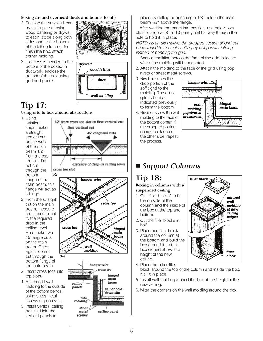
5 Using Easy Up kit (cont.) NOTE: If you wish to offset the tile in the other direction, lay out the tracks as described above. When you stretch the border guide string perpendicular to the tracks, stretch an additional guide string 6 inches closer to the end wall. (See figure 3 and the border note below.) Install the first tile as described in the normal instructions. When you measure for the second tile in the first row, measure from the second string to the wall and cut the tile to that measurement. This will start the offset in the other direction. Install the tile in the first row alternately using the first string, then the second string to cut the tile. Continue installing the tile in this manner and finish the room. Figure 3 BORDER NOTE: If the border tile is less than 9 inches against the wall where the tile will be offset, add three inches to the calculated border. This will eliminate very small borders when offsetting the tile. Tip 15: Using furring strips Calculate the border tile sizes for the room and install the furring strips according to the normal instructions. Snap a chalkline at the border measurement down the center of the second furring strip as directed. If the calculated border on the end wall is less than 9 inches, add 3 inches to it. Using the measurement you get after this calculation, snap a second chalkline at a right angle to the first chalkline using the 3, 4, 5 triangle method outlined in the normal instructions. Once you have the second chalkline marked, snap a third chalkline parallel to the second, 6 inches closer to the end wall. Using this method, you will insure that your border tiles, even though they are offset, are as large as they can be in your room. EXAMPLE If the room measures 14 feet 8 inches by 10 feet 7 inches, the border on the wall parallel to the furring strips will be 9-1/2 inches plus 1/2 inch for the stapling flange (take the 7 inches, add 12 inches, divide by 2 and add 1/2 inch). Snap the first chalkline down the center of the second furring strip 10 inches from the side wall as shown in figure 1. The border perpendicular to the furring strips will be 7 inches (take the 8 inches, add 12 inches, divide by 2 and add 1/2 inch). But that is less than 9 inches, so you add 3 inches to the 7 inches to make 10 inches. Add 1/2 inch for the stapling flange. Snap a second chalkline at a right angle to the first one 10-1/2 inches in from the end wall as shown on figure 1. Now measure 6 inches closer to the wall from the second chalkline and snap a third chalkline parallel to the second as shown in figure 1. Now refer to figure 2 for the suggested sequence of installing the tiles. When you see how the tiles line up with the chalklines in figure 2, and you understand how they are used to line up the tiles in an offset fashion, the exact sequence does not have to be followed to the letter. Overhead Support Beams and Ducts Tip 16: Boxing around overhead ducts and beams 1. Nail 1 x 2 furring strips (cleats) along both sides of the beam. Construct lattices from 1 x 1-1/2 wood furring strips and 1 x 3 center supports spaced 16 on center. Nail the lattices to the cleats. 1 Figure 1 Figure 2 5
6
7 Tip 19: Installing panels around columns, pipes, vents and posts 1. Measure the exact location of the column in relation to the grid opening. 2. Measure the column size and cut a corresponding hole in the panel. Cut the panel face up through the midpoint of the hole. Make all cuts with a very sharp utility knife. Windows Tip 20: Boxing in basement windows: two methods Method One 1. Build a three-sided valance around each window. Use 1/4 plywood for the top. For the three sides, use 1 white pine wide enough to accommodate the ceiling drop and the molding being used. Make certain that the valance is wide enough to allow the window to open and long enough to provide for an open drapery. In most cases, a length of 18 more than the window width is sufficient for the drapery (about 9 on each side of window). NOTE: When cutting #942 and #915, make the cut on the back side of the panel, being careful to cut in the same direction as the facial fissures. Make the cut approximately 1/2 deep. Carefully break the panel along the cut line. 3. Glue scrap pieces of panel material to the back of the board to hold it together. When fitting fiberglass, 1. Measure the exact location of the column in relation to the grid opening. 2. Measure the column size, cut a corresponding hole in the panel and slit once to the nearest edge. 3. Flex the panel into position around the vertical support. For fitting panels around ventilation ducts, 1. Extend ducts to the new ceiling height. 2. Measure accurately and cut the panel to accommodate the duct size. 3. Install the panel. Then attach the grille to the extension. 2. Attach the top of the completed valance to the bottom of the ceiling joists. 3. Install the appropriate wall molding at the level desired. Method Two To box in a basement window, use Armstrong fascia molding. Packed five pieces in a box, this molding is available in 10 lengths and three widths. # fascia molding # fascia molding # fascia molding The molding is finished on the inside and bottom. 1. Notch the front or sides (depending on the joist direction) to fit under the joists. 2. Bend the molding to the indicated shape. Be sure to make the box deep enough for the window to open and make the box wide enough to allow drapes to be installed. In most cases, a length of 18 more than the window width is sufficient for the drapery (about 9 on each side of window). 7
8 Boxing in basement windows Method Two (cont.) 3. Use screws to fasten the flanged ends to the wall. Use angle clips to fasten the front (or sides) to the joists. 4. The bottom lip is already formed to a 15/16 dimension, the same as the field grid. When finishing the corners, use 15/16 outside corner molding covers (Armstrong #7863WH) to close the void. 5. Finish the inside of the box by fastening drywall to the bottom of the joists inside the box. Angle molding can also be fastened to the sides and inside front of the box to allow an acoustical panel to be laid on a slope inside the box to close off the top of the box. Tip 21: Installing decorative molding on boxed-in area If you want to continue using the same decorative molding on the boxed-in areas that you are using on the rest of the room, you should make your box deep enough. For wood molding, allow for the tile and ceiling tile track and clip (1-1/4 ) or the panel and the depth of the suspended ceiling drop, the height of the molding and the desired reveal at the bottom of the molding. If you want to use metal wall molding around the box, again you should allow for the tile track and clip or the Tile Suspended panel and the depth of the suspended ceiling drop. Fasten the molding to the box using finish nails or adhesive. Stairwells Tip 22: Boxing in a basement stairwell 1. Nail 1 x 3 cleats onto the ceiling joists. The distance from the old ceiling height to the new ceiling height will determine the width of the valance material. 1 x 4 or 1 x 6 white pine is most commonly used. 2. Nail valance into cleats. 3. Cover the seam with standard flat molding. 4. Install the appropriate wall molding at the height desired. Ceiling Borders Panels Tip 23: Figuring borders on scored panels or panels with 12 x 12 patterns To make the job look as good as it can, it is important to make even and equal borders. The key to making the borders look their best is to remember the look of the panels. They look like 12 x 12 tile. Therefore, calculate borders like 12 x 12 tile. Here s an example. If the room measures 16 6 x 24 4, the correct borders for 2 x 2 panels would be 15 on two sides and 14 on the other two sides. But with the scoring or pattern on the panels, it would look like a three-inch 12 x 12 border on two sides and a two-inch 12 x 12 border on the other two sides. 8
9 Figuring borders on scored panels or panels with 12 x 12 patterns (cont.) Take the 16 6 dimension. Calculate the border for 12 x 12 tile. It would be 9. The size of the 2 x 2 border panel would then be the 9 plus 12, or 21. The grid should be laid out using the 21 dimension in one direction. Take the 24 4 dimension. Calculate the border for 12 x 12 tile. It would be 8. The size of the 2 x 2 border panel would then be the 8 plus 12 or 20. The grid should be laid out using the 20 dimension in the other direction. Bear in mind that when you lay out the grid this way, the grid may not be centered in the room. The look of 12 x 12 tile, however, will be centered with maximized borders. If the scored or patterned panels are removed later and plain or textured panels are used for replacement, the grid may not be centered, and the borders of the new panels may not be seen. Tip 24: Cutting recessed grid ceiling border panels 1. Trim reveal edge border panels to the same dimensions as for flat panels. The reveal edge detail must now be cut into the panel. 2. Set the panel into the grid. Draw a light pencil line on the panel using the wall molding as a guide. 3. Remove the panel. Use a sharp utility knife and straightedge to cut halfway through the panel from the face side along the pencil line. 4. Lay the utility knife on its side next to the panel and, with the panel face up, cut in at blade height for a reveal cut. 5. Remove the cut strip. 6. Fit the panel into the grid. Tip 25: Cutting reveal edge border panels for crown molding When using a crown molding at the perimeter of a suspended ceiling with reveal edge panels, you can get mouse hole gaps. These holes are created when the tegular panel lays on the molding. To eliminate these holes, cut a normal reveal edge at the panel/molding interface the same cut made when using angle molding. The reveal edge drops in front of the crown molding, and the grid lays directly on the crown molding, eliminating any gaps. In most cases, the cut reveal edge will not readily be seen and does not need to be painted. If the cut edge is visible, the tegular edge should be painted to match the face of the panel. Field Cuts Step Edge Panels Tip 26: Field cutting Occasionally you will have a need for a field panel to be reduced in size to fit around air diffusers, certain light fixtures, along soffits, etc. To produce a panel of reduced size with the stopped edge on all four sides is a tedious procedure, and it does take patience. In reality, what you are doing is removing the center section and reattaching the edge. 1. Cut off the decorative edge. Make sure your cut is not angled but straight up and down. 2. Cut the excess out of the center. 3. Apply white glue to the cut edge. Be careful not to apply glue to any area that will be exposed to view. 4. Carefully align the ends and reattach the decorative edge to the field surface. Apply pressure to ensure a positive adhesive connection. 5. Pin the decorative edge in place using four 6-penny box nails. NOTE: We do not recommend this procedure for border treatments. Instead, see Tip 25 and handle border panels the same way as reveal tile. 9


10 Replacement Panels Tip 27: Replacing ceiling panels at sprinkler head locations For fitting ceiling panels around sprinkler head, the ideal approach would be to remove the sprinkler head, recut a new panel and replace the sprinkler head. Since this is both economically or logistically impossible, we usually end up cutting the replacement panel in half and using an exposed cross tee to conceal the cut and fit the two pieces around the sprinkler. There s another, more attractive option if you are using 942 or 915 fissured ceiling panels. 1. Cut on the back side of the panel, being careful to cut in the same direction as the facial fissures. Make the cut approximately 1/2 deep. 2. Carefully break the panel in half by aligning the cut along the side of a table edge so the break will be straight and sharp. (For fissured panels, the break will usually follow the line of fissuring. When joined, the original cut will literally disappear.) 3. Join the two pieces around the sprinkler head. 4. To assure the joint will not part, apply glue to the raw edges of the break before the panel is installed or you can glue scrap pieces across the back of the cut. You can also place a wall spring between one end of the panel and the web of the grid system. The spring will apply constant pressure, keeping the joint nice and tight. Replacement Tiles Tip 28: Replacing damaged tiles using the Easy Up kit When performing the steps listed below, use caution to avoid damaging the face edges of tiles adjacent to the tile being replaced. Removing the damaged tile 1. Make four cut lines in the tile being removed. Always cut from the edge of the tile into the center. 2. After the cuts are made, remove the center section. 3. One at a time, slide the remaining tile sections toward the open center section, and let them drop out. 4. Carefully slide the remaining sections of the tile about 1 toward the center opening. This will allow all remaining sections of the damaged tile to drop out. 5. When the damaged tile is removed, you will see the ceiling tile clip which held up the damaged tile. 6. Slide the clip into the opening and remove it from the track. 7. Reverse it and snap it back on the track. 8. Slide the clip so that the teeth are just above the tongue of the adjacent tile. 9. Use a screwdriver and a hammer to push the clip into the tile above the tongue. Installing the new tile 10. Take a new tile and remove both flanges. 11. Trim flange edges back 1. Insert the knife blade only deep enough to remove the 1/8 thick flange. It must not penetrate the face of the tile. 12. Remove about 1-1/2 of tongue in one of the corners adjacent to one of the removed flanges. 13. Hold the new tile up in the opening and on the back of the tile mark where the sides of the ceiling tile track are. 10


11 Replacing damaged tiles using the Easy Up kit (cont.) 14. Use these marks as a guide to force a clip into the edge of the tile where the flange was removed. 15. With the tongue sides of the new tile slightly offset to the adjacent tile, insert the partial tongue into the adjacent tile. You will have to push up on the side where the 1-1/2 of tongue was removed to allow the tile to flex slightly. 16. Push the partial tongue of the tile into the groove of the adjacent tile. 17. Push up on the other tongue side and push the tile toward the other tile to insert the full tongue into the adjacent tile. 18. When this replacement tile is lined up with the other tile, push up so the clip snaps onto the track. Lighting Tip 29: Hanging 2 x 4 lights When installing 2 x 4 drop-in lights in a suspended ceiling, don t forget to install additional hanger wires in the corners of the light. Additional wires may be needed for reinforcement of other fixtures mounted in or on the ceiling. For example, some recessed lights may need additional hanger wires when the fixture is heavy. Place the additional wires near the support for the fixture or independently support the fixture. Tip 30: Installing recessed lighting in a tile ceiling When installing a recessed light in a tile ceiling, make sure the light is supplied with support bars. These support bars will fit between the joists and hold up the light fixture so it does not rest on the back of the tile. Mount the support bars so the face of the fixture is flush with the face of the tile. Tip 31: Installing recessed lighting in a suspended ceiling NOTE: Incandescent lights, even in reflective high hat or can fixtures, are too hot for plastic surfaced panels, such as fiberglass. 1. Because recessed lights are usually smaller than grid openings, these fixtures should be installed on a subframe. Use extra hanger wires to support the components at the subframe attachment points. 2. Use fixtures with support bars that will rest on the grid. (The alternative is to install an independently hung fixture.) 3. Cut an appropriate fixture opening in the panel. 4. Finish with a trim ring or grille. NOTE: No matter what type of lighting fixture is used, all manufacturers requirements must be met. Both lighting and ceiling components are designed with certain circumstances in mind; these conditions must be compatible. Never use incandescent lights in fire-rated applications. 11
12 Tip 32: Installing surface-mounted lighting in a suspended ceiling Support surface-mounted light fixtures and lightweight items with a wood attachment beam mounted above. 1. Measure the distance between the webs of main beams or cross tees and cut a 2 x 4 piece of lumber to this exact length. 2. Lay the wood section on top of the panel, and secure by running two 2 screws through the web of the grid member and into the wood ends. This provides a solid material that is able to receive attachment fasteners for surface-mounted lights or track supports. 3. To help carry any extra load in the grid system, add extra hanger wires to the grid where it attaches to the wood section. Tip 33: Installing surface-mounted lighting in a tile ceiling When you install a surface-mounted light under a tile ceiling, you must secure the light to the joists or furring strips using screws that will allow at least 1 of the threaded portion of the screw to penetrate the wood. With incandescent lighting, use the correct wattage lamps as indicated by the manufacturer. If the light is fluorescent, you may have to leave a space between the back of the light and the face of the tile ceiling to allow air to circulate. When fixtures are installed against the face of the tile without the air space, the ballast may overheat and burn out more frequently. Tip 34: Mounting a ceiling fan in a tile ceiling When installing a fan brace where an electric fixture is not already located, the bracket and electrical box should be mounted so that the face of the box is flush with the finished ceiling. 1. If a furring strip or ceiling tile track line up with the electrical box, cut the furring strip or ceiling tile track so it does not interfere with the box opening. Continue the furring or track on the other side of the box. 2. Cut a hole in the tile to fit around the box at least 1/4 larger than the box. Leave some clearance around the box. 3. After the tiles are in place, mount the fan to the box and install the ceiling fan trim ring against the face of the tile. Use only mounting brackets and electrical boxes recommended for ceiling fan installation. Follow the manufacturers directions for their installation. When installing a ceiling fan brace in either a panel or tile ceiling where an electric fixture is already located: 1. Remove the existing ceiling outlet box and bar. 2. Clear the joist space above the ceiling opening of insulation, wiring, etc. 3. Check the location of existing wiring. Remove wiring away from the sides of the joist so it will not be caught behind feet of fan brace. 4. Follow the fan brace manufacturer s instructions for mounting the brace. 5. Reverse the position of the fan brace feet so the feet are up. This will allow the electrical box to extend downward so the face of the box is flush with the finished ceiling. The drop of the ceiling using furring is 1-1/4. Vents and Recessed Fans Tip 35: Mounting ceiling vents When you install a power vent in a ceiling to exhaust the air in a bathroom or other area, you must mount the fixture in much the same way as a light fixture or speaker. The fixture must be self-supported. No weight of the fixture may rest on the ceiling tile or panels. Follow fan manufacturer s instructions. 12
13 Audio Speakers Tip 36: Installing audio speakers 1. Determine the speaker location. Remove the panel in that location. 2. Cut a hole the size and shape of the speaker. 3. Paint the grille to match the panel where an integrated look is required. 4. Follow the manufacturer s mounting recommendations for the speaker, but make sure the weight of the speaker and grille is supported either by the grid or independent supports not the ceiling tile or panels. Additional hanger wires may be needed to support the grid. See Tip 33 for additional support instructions. Cathedral Ceilings Tip 37: Installing plank on a cathedral ceiling Always begin the installation at the bottom and work up to the peak. Run the plank horizontally across the plane of the ceiling, the direction real planks would run. 1. The joists will run from the bottom of the ceiling to the top. Fasten a furring strip to the bottom of the joists (rafters) where the ceiling plane meets the bottom wall. 2. Fasten furring strips horizontally every 4 until you get to the top of the peak. 3. Fasten the last furring strip about 2 from the peak. 4. If the joists are not even on the bottom, the furring must be shimmed to flatten it. If the furring strips are not long enough to reach the other end of the room, they must be butted. The butt joints must occur under a joist, and both ends must be double-nailed or screwed to the joist. 5. When all the furring is installed, start installing the ceiling tile tracks. The tracks will run perpendicular to the furring and fasten to the furring. Use drywall screws that allow the thread to fully penetrate the furring. 6. At both ends of the room, install ceiling tile tracks 1 from each end wall, running from the bottom of the ceiling plane to within 1 of the peak. The rest of the tracks should be installed parallel to the end tracks on 12 centers. 7. Cut a piece of wood to make a starter strip and fasten it to the wall. Cut it at an angle to fit against the wall and have the bottom of the starter strip parallel to the plane of the ceiling. The bottom edge of the starter strip should be flush with the finished face of the ceiling. 8. Measure the straight line distance from the bottom of the ceiling to the top. Figure the width of the border planks so the bottom plank and the top plank are equal. Stretch a string from one end wall to the other to use as a guide string for cutting the width of the first row of plank. 9. Always start the installation from the bottom and go to the top. Let gravity work for you, not against you. When you get to the last row of plank, cut the last row so it ends 1 from the peak. 10. With both sides of the ceiling done, determine the size of the divider at the top. You will not know what size to cut this piece until the plank reaches the top. Its size depends on the angle of the ceiling and the width of the trim molding you use to cover the peak. Do not attempt to have the planks meet each other at the peak without using a divider. The movement of the house will open and close the joist that you so meticulously fitted. 11. In this illustration, the divider is fitted to a peak without a ridge pole. Cut the piece to fit the detail in your ceiling. Cover the gap with a trim molding. Tip 38: Installing molding or trim between a suspended panel cathedral ceiling and wall: two options There are two ways to bridge between a suspended cathedral ceiling and the wall. Method One Bend the wall molding on a sheet-metal bending brake to the correct angle. Method Two Cut a piece of wood trim at the correct angle and fasten molding to wood. 13
14 Insulation Tip 39: Installing insulation When an installation calls for insulation on the back of a ceiling, you must be careful how the insulation is applied. With Armstrong #420 and 421 high-performance fiberglass panels, you can lay 2 x 4 batts of R-19 insulation that fit on the backs of panels quite nicely. Do not lay insulation directly on the back of tile or other types of panels. An air space must remain between the back of the panels and the insulation. Create this air space by laying furring strips, wall molding, 12-gauge hanger wire or any number of other rigid supports across the top of the main beams. These rigid members will carry the weight of the insulation and transfer the weight to the mains, leaving an air space between the back of the panels and the insulation. With tile ceilings, the application of insulation is done less frequently. In most cases, there is no room to apply insulation. If there is room for insulation, make sure that there is an air space between the insulation and the back of the tile. Chicken wire or other wire mesh can be laid over the back of the ceiling, and insulation can be blown in on the wire mesh. The ceiling tracks or furring will then carry the weight of the insulation. Miscellaneous Tip 40: Installing tile where kitchen cabinet doors are close to the ceiling When kitchen cabinet doors are less than 1-1/2 from the ceiling, there is not enough clearance to install ceiling tile tracks or wood furring since they would create a drop of 1-1/4. The only installation method which will allow the doors to open is the cement method, using ceiling tile adhesive. Making sure the existing ceiling is level, follow the directions from the cement manufacturer to prepare the surface and apply and place the cement. Tip 41: Removing dirt from tile and panel surfaces Pencil marks, metal marks, smudges or dirt may be removed from a tile and panel surface with an art gum eraser. 14
15 Ceiling Solutions From The Name You Can Trust TM RC J Printed in United States of America
CEILING SYSTEMS. Between us, ideas become reality. Installing. Suspended Ceilings. International Version
 CEILING SYSTEMS Between us, ideas become reality Installing Suspended Ceilings International Version 1 Installing Armstrong Suspended Ceilings An Armstrong suspended mineral fiber ceiling is functional,
WoodWORKS Channeled Plank
 CEILING&WALL SYSTEMS Between us, ideas become reality WoodWORKS Channeled Plank Assembly and Installation Instructions 1. General 1.1 Product Description WoodWorks Channeled acoustical ceiling and wall
How to Install the QuickHang Installation Kit
 FOR RESIDENTIL USE: The QuickHang hardware in this kit is designed to work with solid wood and engineered wood joists in residential ceiling applications. KIT INLUDES: (3) 6' Main beams (9) ross tees (9)
METALWORKS Linear (Interior & Exterior Applications)
") CEILING&WALL SYSTEMS Between us, ideas become reality METALWORKS Linear (Interior & Exterior Applications) Assembly and Installation Instructions 1. GENERAL 1.1 Product Description MetalWorks Linear is
CEILING&WALL SYSTEMS Between us, ideas become reality METALWORKS Linear (Interior & Exterior Applications) Assembly and Installation Instructions 1. GENERAL 1.1 Product Description MetalWorks Linear is
METALWORKS Linear (Interior & Exterior Applications)
") METALWORKS Linear (Interior & Exterior Applications) Assembly and Installation Instructions 1. GENERAL 1.1 Product Description MetalWorks Linear is a linear metal ceiling system with either a Connections
METALWORKS Linear (Interior & Exterior Applications) Assembly and Installation Instructions 1. GENERAL 1.1 Product Description MetalWorks Linear is a linear metal ceiling system with either a Connections
Gambrel Barn with Overhang Manual
 Tools Needed: -Cordless Drill (12V or higher) -#2 Square Drive Bit -Hammer -6 Step Ladder -Tape Measure -Square utility knife w/ blade & hook blade -Speed Square Little Cottage Co. PO Box 455 Berlin, OH
INSTALLATION INSTRUCTIONS
 INSTALLATION INSTRUCTIONS 5-in x 84-in x 3/8-in 12.7 cm x 213.36 cm x 9.525 mm 10 planks 29 sq.ft. IMPORTANT INFORMATION Open cartons 2-3 days prior to the install and allow material to adjust to the relative
METALWORKS TARTAN PANELS General Installation Instructions
 CEILING SYSTEMS METALWORKS TARTAN PANELS General Installation Instructions 1. GENERAL 1.1. Product Description MetalWorks Tartan system is a combination of metal ceiling panels available in a range of
Mach Wall Installation Instructions
 Mach Wall Installation Instructions Planning the Job Since Mach Wall is an innovative product that accomplishes 3 tasks at the same time (frame, insulate and drywall) and it replaces traditional framing,
INSTALLATION PROCEDURE
 Vinyl Siding INSTALLATION PROCEDURE Tools Needed and Preparation MOST ESSENTIAL TOOLS The proper tools, materials and equipment can make the installation of Durabuilt Vinyl Siding much easier. Here are
Dura-Lock Roof System
 DLR-14 Dura-Lock Roof System Assembly and Installation Instructions Read the instructions before starting the job. They explain the steps required to produce a finished product that will meet factory specifications.
Tools needed. Supplies Needed
 Installation Guide Key System Components Main beam Cross tee Tools needed Chalk line Drill (cordless) ¼" drill bit Hammer Miter saw Pencil String line(s) Stud finder Tape measure ½" to 1" wood chisel Calculator
INSTALLATION INSTRUCTIONS
 INSTALLATION INSTRUCTIONS 5-in x 84-in x 3/8-in 12.7 cm x 213.36 cm x 9.525 mm 10 planks 29 sq.ft. IMPORTANT INFORMATION Open cartons 2 3 days prior to the install and allow material to adjust to the relative
Trim (Aluminum Substrate)
") CEILING SYSTEMS Between us, ideas become reality Trim (Aluminum Substrate) GENERAL Description WoodWorks Trim (aluminum substrate) is a unique system designed for use with Tegular, Vector, Linear and Channeled
CEILING SYSTEMS Between us, ideas become reality Trim (Aluminum Substrate) GENERAL Description WoodWorks Trim (aluminum substrate) is a unique system designed for use with Tegular, Vector, Linear and Channeled
Installing your new Bevella Top. L Shaped Countertop with Joints No Finished Ends (Fits Between Four Walls)
") Installing your new Bevella Top L Shaped Countertop with Joints No Finished Ends (Fits Between Four Walls) Bevella RTI Countertops are engineered and manufactured to the highest quality standards, built
Installing your new Bevella Top L Shaped Countertop with Joints No Finished Ends (Fits Between Four Walls) Bevella RTI Countertops are engineered and manufactured to the highest quality standards, built
METALWORKS Linear (Interior & Exterior Applications)
") METALWORKS Linear (Interior & Exterior Applications) Assembly and Installation Instructions METALWORKS LINEAR ITEMS: Item # Item Name Incl with planks Sold by the: Pcs/Ctn 8121 96 x 2 x 5/8" MetalWorks
METALWORKS Linear (Interior & Exterior Applications) Assembly and Installation Instructions METALWORKS LINEAR ITEMS: Item # Item Name Incl with planks Sold by the: Pcs/Ctn 8121 96 x 2 x 5/8" MetalWorks
METALWORKS Concealed. Installation Instructions
 METALWORKS Concealed Installation Instructions 1. GENERAL 1.1 Product Description MetalWorks Concealed ceilings consist of perforated and unperforated panels that are downward accessible, and are designed
Installation Instructions Split Shake, Staggered Shake, Shingle, Perfection Shingle, and Shapes
 Installation Instructions Split Shake, Staggered Shake, Shingle, Perfection Shingle, and Shapes General Guidelines These instructions show one type of installation and are intended for the professional
Metallaire Installation Instructions
 CEILING INSTALLATION INSTRUCTIONS NAIL-UP INSTALLATION CAUTION: The edges of the metal panels are sharp! Wear heavy protective gloves when handling the metal panels. Metallaire panels are steel and designed
Installation Manual MODEL ANE-42
 Installation Manual MODEL ANE-42 GET TO KNOW YOUR UNIT 1 2 1. CROSS BRACES 2. SIDE BRACKETS - Stud Finder - 12-14 Level - Tape Measure - Small Flathead Screwdriver Tools Needed: - Electric Drill (with
Installation Manual 0318
 Installation Manual 0318 DOUBLE 7 CEDAR SHINGLE INSTALLATION GUIDE General Information CAUTION: REMEMBER THAT POLYMER UNDERGOES EXPANSION / CONTRACTION DUE TO VARIATIONS IN TEMPERATURE. THE FOLLOWING INSTRUCTIONS
Panel Grille Suspended Ceiling Installation Guide
 Panel Grille Suspended Ceiling Installation Guide World Commerce Center 2000 Ring Way Road, St. Augustine, FL 32092 Phone: 800-227-8566 or 904-584-1400 www.rulonco.com Receipt and Storage: a. All material
FRAMED CABINETRY INSTALLATION MANUAL
 FRAMED CABINETRY INSTALLATION MANUAL AN INDUSTRY GUIDE FOR PROFESSIONAL INSTALLATION RESULTS TO AVOID DAMAGE OR INJURY, READ IN ENTIRETY BEFORE STARTING MATERIAL & TOOL LIST FOR INSTALLATION Safety Glasses
Panel Installation Instructions
 EXTREMELY IMPORTANT INFORMATION PLEASE READ ENTIRE PACKET! Warranty Is Void If Panels Not Installed According to Instructions 1. WARNINGS & SPECIAL NOTES 1.1 Keep panels 24 from Heaters and shield Radiant
Chapter 1. Beam and Sill Plates
 Chapter 1. Beam and Sill Plates 1.1 ESTABLISHING SQUARE SILL PLATE CHALK LINES 1.2 INSTALLING TREATED SILL PLATES 1.3 INSTALLING LAMINATE BEAM Tools needed by volunteers: Hammer Nail apron Tape measure
3.1 Continuous top and bottom lock 3.2 Engineered nailing hem 3.3 Temperature markings
 AOBP recommends 2-1/2 ring shank nails be used. Installation over foam will require longer fasteners to assure a penetration of at least 3/4 into a structural member (stude or nail base). Corner accessories
metalworks Plank Assembly and Installation Instructions 2.1 Read this entire document before proceeding with installation.
 metalworks Plank Assembly and Installation Instructions 1. GENERAL is a ceiling system made up of standard sized hook-on planks fabricated from galvanized steel and powder coated to provide a damage and
Cabinetry Installation
 Cabinetry Installation Easy to follow step-by-step kitchen cabinet installation Hammer Pry bar Screwdriver Phillips Flathead Level TOOL AND MATERIAL LIST Tape measure Pencil Straight edge Drill 3/16" drill
Extra Wide Heavy Duty Plastic Lockers Series Locker Installation Instructions
 Locker Installation Instructions Thank you for selecting Extra Wide Heavy Duty Plastic Lockers. We are confident that the quality and construction of the lockers will prove to be a good investment. These
CONTENTS. Transitions Board and Batten Vertical Installation... 10,11
 INSTALLATION MANUAL CONTENTS Important Notes... 2-4 Weather Protective Barriers... 2 Storage and Transportation... 2 Tools and Equipment... 2 Fastener Choices... 3 Wall Preparation... 3,4 Flashing... 4
CertainTeed Ceilings
 CertainTeed Ceilings 7 Ecophon Focus Dg 2x2, 2x4, 2x5, 2x6, 2x8 Installation Instructions 5 2 3 6 4 1 Components: 1. Ecophon Focus Dg Panel (2 x2-8 ) 2. CertainTeed 15/16 Classic Main Runners 3. Certainteed
Chapter 33: Lofts (Or Second Floors)
") Chapter 33: Lofts (Or Second Floors) Most Common Mistakes: 1. Designing loft yourself and installing later. 2. Inadequate height either below or above. 3. Not enough headroom for stairs. 4. Failure to
Chapter 33: Lofts (Or Second Floors) Most Common Mistakes: 1. Designing loft yourself and installing later. 2. Inadequate height either below or above. 3. Not enough headroom for stairs. 4. Failure to
With Illustrations, Drawings & Step By Step Details. Click Here To Download 12,000 Shed Plans. 1 P a g e Download 12,000 More Shed Plans
 With Illustrations, Drawings & Step By Step Details Click Here To Download 12,000 Shed Plans 1 P a g e Download 12,000 More Shed Plans Table of Contents OVERVIEW... 3 MATERIALS & CUTTING LISTS... 4 DRAWINGS,
PRE-ENGINEERED HORSE STALL SYSTEMS SDFD SLIDING DOOR c/w FOLD-DOWN GRILL. & Assembly. Installation Instructions
 PRE-ENGINEERED HORSE STALL SYSTEMS 4800 SDFD SLIDING DOOR c/w FOLD-DOWN GRILL & Assembly Installation Instructions 4800 SDFD Sliding Door c/w Fold-Down Grill Components - 1 3 /4" x 2" x 88" channels (2)
Layout and Fitting. Chapter 6 Layout and Fitting
 6 Layout and Fitting A. RESILIENT SHEET FLOORING Layout and Fitting There are three general methods of fitting resilient sheet flooring into a room: freehand knifing, direct (or straight) scribing and
AXIOM Classic Trim. Assembly and Installation Instructions 1. GENERAL
 AXIOM Classic Trim Assembly and Installation Instructions 1. GENERAL 1.1 Description Axiom Classic Trim is a perimeter trim system designed for use with a variety of Armstrong suspension systems. Classic
Shapes Siding. Perfection Shingles. Chalk Line
 Snap a Chalk Line Shapes Siding Perfection Shingles Chalk Line To establish a straight reference line to guide the positioning of the starter strip and the first course of siding, snap a chalk line. starter
Exterra Installation Guide
 Exterra Installation Guide Installing the foam padding Please review this installation guide before you begin installing the floor. If you have any questions, please call us at 800-428-5306 any time Monday
Installation Manual SOLID CORE SIDING
 Installation Manual SOLID CORE SIDING SOLID CORE SIDING Installation Information contained in this manual can be viewed in video form at: www.youtube.com/epbc CONTENTS Important Notes...2-4 Weather Protective
14.0 SIDING AND SOFFITS SECTION
 14.0 SIDING AND SOFFITS SECTION 1. Introduction At the present time, Habitat homes in St. Louis are being sided in vinyl. This is to keep the price down, and to provide the homeowner with a relatively
GE Monogram. Installation. Instructions. Microwave Oven. Under Cabinet Installation. and. JX827 Series Built-In Kit. Models.
 GE Monogram Installation Instructions Under Cabinet Installation and JX827 Series Built-In Kit Models ZEM200 Series CAUTION WARNING Before you begin Read these instructions completely and carefully. IMPORTANT:
GROWING BETTER THROUGH DESIGN. 6ft Lean-To LEAN-TO. Assembly Instructions 04/02
 GROWING BETTER THROUGH DESIGN 6ft Lean-To LEAN-TO Assembly Instructions 04/02 6ft Lean-To Greenhouse Base Plan Introduction/Tools/Contents / / Contents This is a copy of our Lean-To greenhouse base plan.
CABINET INSTALLATION INSTRUCTIONS
 CABINET INSTALLATION INSTRUCTIONS Please read these instructions through completely before beginning the installation. Thank you for choosing Plato Personalized Custom Cabinetry for your home. Your Plato
AXIOM Classic Trim. Assembly and Installation Instructions
 AXIOM Classic Trim Assembly and Installation Instructions 1. GENERAL 1.1 Description Axiom Classic Trim is a perimeter trim system designed for use with a variety of Armstrong suspension systems. Classic
Laminate Cabinet Installation Instructions
 Laminate Cabinet Installation Instructions www.easygaragestorage.com/installation How To Use These Instructions Thank you for your purchase! Please read each step of this manual thoroughly to ensure proper
metalworks Vector Assembly and Installation Instructions
 metalworks Vector Assembly and Installation Instructions 1. GENERAL 1.1 Product Description MetalWorks Vector is a downward accessible galvanized steel ceiling panel available in standard 24" x 24" size.
Octagon Vinyl Gazebo Assembly Instructions For 10 & 12 Models
 Octagon Vinyl Gazebo Assembly Instructions For 10 & 12 Models Toll Free: 866.768.8465 Hours: 9-5 Monday-Friday EST www.homeplacestructures.com Package ships as shown revised 04/29/09 Vinyl Gazebo Assembly
AXIOM Classic Trim Installation Instructions
 CEILING SYSTEMS AXIOM Classic Trim Installation Instructions 1 GENERAL 1.1 Description Axiom is a perimeter trim system designed for use with most of Armstrong s suspension systems. It is available through
Flash Coving. Chapter 8 Flash Coving 8. 1
 8 Flash Coving Chapter 8 Flash Coving 8. 1 Flash Coving A. TOOLS In addition to the normal tools (knives, dividers, recess scribers, straightedges, rollers, trowels, etc.), other tools are also needed
Panel Installation Instructions
 EXTREMELY IMPORTANT INFORMATION PLEASE READ ENTIRE PACKET! Warranty Is Void If Panels Not Installed According to Instructions 1. WARNINGS & SPECIAL NOTES 1.1 Keep panels 24 from Heaters and shield Radiant
Zenterra TM Installation Guide
 Zenterra TM Installation Guide Installing the foam padding Please review this installation guide before you begin installing the floor. If you have any questions, please call us at 800-428-5306 any time
WOODWORKS Walls. Installation Instructions WALL
 WALL Systems Between us, ideas become reality WOODWORKS Walls Installation Instructions 1. GENERAL 1.1. Product Description WoodWorks walls consist of 2' x 4', 2' x 8', 2' x 9' or 2' x 10' perforated and
Assembly Instructions
 10' and 12' Octagon Cedar Gazebo Assembly Instructions Toll Free: 866.768.8465 Hours: 9-5 Monday-Friday EST www.homeplacestructures.com Package ships as shown revised 06/20/09 Cedar Gazebo Assembly Instructions
Installation Manual MODEL NE-42
 Installation Manual MODEL NE-42 GET TO KNOW YOUR UNIT 1 1. CROSS BRACES - Stud Finder - 12-14 Level - Tape Measure - Small Flathead Screwdriver Tools Needed: - Electric Drill (with 1/4 & 1/8 drill bit)
Installation Instructions
 www.marlite.com Effective Date 03/01/2018 ARTIZAN FRP, SYMMETRIX FRP, ENVUE FRP, STANDARD FRP Installation Instructions Statements expressed in this technical bulletin are recommendations for the application
Chapter 14. Wall Sheetrock
 Chapter 14. Wall Sheetrock 14.1 PREPARATION 14.2 PLANNING 14.3 GENERAL INSTALLATION RULES 14.4 INSTALLING WALL SHEETROCK 14.5 FINISHING AND CLEANUP Tools needed by volunteers: Nail apron Tape measure Utility
129 KITCHEN BASE CABINET 480
 129 KITCHEN BASE CABINET 480 There are two sorts of kitchen cabinets: base cabinets, which sit on the floor, and wall cabinets. Base cabinets provide both storage space and work surfaces. They often house
Layout and Fitting. Chapter 6 Layout and Fitting 6. 1
 6 Layout and Fitting Chapter 6 Layout and Fitting 6. 1 Layout and Fitting A. RESILIENT SHEET FLOORING There are three general methods of fitting resilient sheet flooring into a room: freehand knifing,
Description. Lesson Outcomes. Assumptions. Build a Floor. Carpenter
 Carpenter Description Floors are an integral part of residential construction and must be built to specifications that meet building code requirements. In this Activity Plan, students will be cutting and
FOLDING DOOR - FOR FACTORY ASSEMBLED JAMBS WITH APPLIED SILL
 FOLDING DOOR - FOR FACTORY ASSEMBLED JAMBS WITH APPLIED SILL READ SPECIFIC INSTALLATION INSTRUCTIONS COMPLETELY BEFORE STARTING ANY INSTALLATION Failure to install and maintain our product according to
Installation Guidelines
 Installation Guidelines Tando Building Products provides these instructions as general guidelines only. Tando Building Products neither installs exterior cladding nor has any control over any installation.
Installation Guide. Model #400. Corporate Office: 349 Highland Road East Macedonia, Ohio
 Installation Guide Model #400 Corporate Office: 349 Highland Road East Macedonia, Ohio 44056 1.866.822.7328 www.ezbreathe.com Copyright 2006, EZ Breathe, LLC WHAT S INSIDE Before installing your EZ Breathe
Assembly and Installation Guide
 The Easy Hang Closet Solution SM Install Your elfa In An Instant. Enjoy The Benefits For A Lifetime. Basic Tools For elfa Assembly and Installation Level Hand or Power Drill Drill Bits 1/8", 3/8", 5/16"
Revision Date: April 01, Paramount Enclosure
 Paramount Enclosure www.urbanindustries.com 15 Urban Industries, Inc. 2008 Tools The following tools are recommended for the installation of the Paramount Aluminum Enclosure and roof. 1 2 Level 1 4 Level
Installation And Care Instructions. Vertical Honeycomb Shades
 Installation And Care Instructions Vertical Honeycomb Shades Rev 5/2013 Table Of Contents Getting Started... 3 Parts Overview... 4 Materials Required... 5 Tools Required... 6 Outside Mount Installation...
LUX INSTALLATION GUIDE. LUX Panel V Groove Installation. Installation Guide. February
 LUX Panel V Groove Installation Installation Guide February 2017 www.luxpanel.ca LUX Panel V Groove Installation LUX panel steel cladding is designed to be installed vertically, horizontally, diagonally
ROOFING APPLICATION STANDARD (RAS) No. 115 STANDARD PROCEDURES FOR ASPHALTIC SHINGLE INSTALLATION
 No. 115 STANDARD PROCEDURES FOR ASPHALTIC SHINGLE INSTALLATION") ROOFING APPLICATION STANDARD (RAS) No. 115 STANDARD PROCEDURES FOR ASPHALTIC SHINGLE INSTALLATION 1. Scope 4. Underlayment 2. 1.1 This roofing application standard has been developed to provide a responsive
ROOFING APPLICATION STANDARD (RAS) No. 115 STANDARD PROCEDURES FOR ASPHALTIC SHINGLE INSTALLATION 1. Scope 4. Underlayment 2. 1.1 This roofing application standard has been developed to provide a responsive
Building An Outdoor Playhouse
 Building An Outdoor Playhouse If you want to give the children in your family their own retreat and improve your do-it-yourself skills at the same time, this playhouse is the perfect project for you. Not
Your sauna can be placed on concrete, tile, linoleum, or any surface that does not absorb water. Do not install the sauna on carpeting.
 Custom-Cut Sauna Kit installation instructions Please immediately check for any hidden damage that may have occurred in shipping. If any damage is found you must notify the delivering carrier within seven
Linear Open Style Suspended Ceiling Installation Guide
 Linear Open Style Suspended Ceiling Installation Guide World Commerce Center 2000 Ring Way Road, St. Augustine, FL 32092 Phone: 800-227-8566 or 904-584-1400 www.rulonco.com Receipt and Storage: a. All
Office Installation Guidelines
 UH Structures Inc. dba Ebtech Industrial 2241 Industrial Drive Connellsville, PA 15425-6181 Telephone: 724-628-6100 Fax: 1-412-774-2429 www.ebtechindustrial.com Office Installation Guidelines INTRODUCTION
Chapter 23. Garage Construction
 Chapter 23. Garage Construction 23.1 ESTABLISHING CHALK LINES 23.2 MEASURING AND CUTTING WALL PLATES 23.3 MARKING WINDOW & DOOR LOCATIONS ON EXTERIOR WALL PLATES 23.4 MARKING STUDS ON EXTERIOR WALL PLATES
Installation Guidelines
 Page 1 Tools You ll Need 4 ft. Carpenter s level Chalk line (to mark U channel locations) Cordless drill/nut driver Caulking gun Chop saw with a metal cutting blade on it (required to make accurate and
Build Like a Pro: Building a Deck
 This is an excerpt from the book Build Like a Pro: Building a Deck by Scott Shuttner Copyright 2002 by The Taunton Press www.taunton.com JOISTS PRO TIP Step up to a larger joist whenever you come close
HipMaster Installation Instructions
 Mid-America, Plus and HipMaster Installation Instructions New applications for metal, slate and wood shingle roofs (see page 7) CAUTION: Before beginning installation read all general guidelines, special
MAGNUM BOARD INTERIOR INSTALLATION GUIDELINES
 TECHNICAL BULLETIN No.: 090509-1405 Subject: Issue Date: September 4, 2009 Issue No.: II MAGNUM BOARD INTERIOR INSTALLATION GUIDELINES 1. CUTTING MAGNUM BOARD You can easily cut Magnum Board with carbide
Safety First! Review the Safety Checklist before performing tasks in this chapter.
 Chapter 17. Cabinets 17.1 LAYING OUT KITCHEN CABINET UPPER UNITS 17.2 INSTALLING KITCHEN CABINET SUPPORT STRIPS 17.3 INSTALLING KITCHEN CABINET UPPER UNITS 17.4 INSTALLING RANGE HOOD 17.5 INSTALLING KITCHEN
AWNING / PATIO COVER INSTALLATION INSTRUCTIONS
 AWNING / PATIO COVER INSTALLATION INSTRUCTIONS Before You Begin Read the installation instructions thoroughly before beginning the installation procedure. Perspective In the Awning Instructions, Back means
Installation Instructions Palladium Wall Panels - Demountable Factory Finished Edges and Field Cut Edges
 Please read all instructions before installing Palladium Wall Panel System. 1. Before installation: a. Acclimate Palladium Panels, reveals, adhesives and wall substrates to room temperature 24 hours before
ECOPHON Focus Ds 4x4 Installation Manual
 ECOPHON Focus Ds 4x4 Installation Manual Read the entire manual before installing. Suited only for seismic categories, B 8 9 10 5 7 6 1 2 4 Ecophon Focus Ds Panel (4'x4') 1 7 Connect Wall Bracket T-profile
Manually adjustable blades Return air VAV cooling only VAV cooling and warm up heating TF-D TF-RA TB-C TB-CW
 FORM 10.3 REV 0407 THERM-FUSER THERMLLY POWERED VV DIFFUSER CEILING PPROCHES MODULR VV SYSTEMS Models: TF-C VV cooling only. TF-CW VV cooling and warm up heating TF-HC VV cooling and VV heating TF-D TF-R
Chapter 11. Siding and Soffit
 Chapter 11. Siding and Soffit 11.1 SIDING PREP 11.2 INSTALLING HOUSE SIDING 11.3 INSTALLING SHED SIDING 11.4 INSTALLING SOFFIT 11.5 INSTALLING FASCIA 11.6 INSTALLING SHUTTERS 11.7 SITE CLEANUP Tools needed
Best Barns USA Assembly Book
 Best Barns USA Assembly Book Revised February 4, 2016 the Millcreek-R 12'x 20' Manufactured by Reynolds Building Systems, Inc. 205 Arlington Drive Greenville, PA 16125 724-646-3775 This manual is copyrighted.
Closet System Installation Manual
 Closet System Manual Thank you For choosing our Custom Closet Collection to fit all your needs Closets come fully assembled to make your project an enjoyable and satisfying experience. With quality Custom
INSTALLATION AND CARE INSTRUCTIONS
 INSTALLATION AND CARE INSTRUCTIONS Vertical Applications Honeycomb Shades 52 C8-10-3401 Rev 2/14 CONTENTS Introduction...2 Before You Begin...3 Vertical Application Parts Overview...4 Materials Required...5
Wallgard 1,3 product
 INSTALLATION INSTRUCTIONS Wallgard 1,3 product October 2015 GENERAL Application can be done to smooth, dry, clean, sound walls of concrete, plaster, hardboard, plywood and fibreboard. Board material must
EZ Shed. Tool eeded ST MER SER I E
 00 EZ Shed PLEASE READ ALL INSTRUCTIONS AND HELPFUL HINTS CAREFULLY BEFORE CONSTRUCTION Tool eeded ST MER SER I E 203 591-9032 - 30-5 30 INSTRUCTIONS 1. Separate and stack all parts included in kit. STUD
WOODWORKS. Linear Solid Panels. Installation Instructions CEILING SYSTEMS. 1. General
 CEILING SYSTEMS Between us, ideas become reality WOODWORKS Installation Instructions Linear Solid Panels 1. General 1.1 Product Description WoodWorks Linear features a solid wood ceiling system in 1' x
Best Barns USA Assembly Book
 Best Barns USA Assembly Book Revised June 14, 2017 the Belmont-R Building Size 12' x 24' Manufactured by Reynolds Building Systems, Inc. 205 Arlington Drive - Greenville, PA 16125 This manual is copyrighted.
Best Barns USA Assembly Book
 Best Barns USA Assembly Book Revised September 12, 2017 the Arlington Building Size 12' x 20' Manufactured by Reynolds Building Systems, Inc. 205 Arlington Drive Greenville, PA 16125 This manual is copyrighted.
10. Vents, Baffle Guard and Blocking
 10. Vents, Baffle Guard and Blocking 10.1 INSTALLING BATH FAN AND END CAP 10.2 INSTALLING RANGE PLENUM AND END CAP 10.3 INSTALLING PROPER VENTS 10.4 INSTALLING WIND WASHING BAFFLE GUARD 10.5 INSTALLING
Installation Guide. Capped Cellular PVC Fencing. Table of Contents. Storage and Handling Tools Needed Fence Layout and Locating Posts
 Capped Cellular PVC Fencing Installation Guide Table of Contents Storage and Handling Tools Needed Fence Layout and Locating Posts Installation instructions 4 x 4 Over Sleeve Post - 3.5 Rail Privacy Shadowbox
Best Barns USA Assembly Book
 Best Barns USA Assembly Book Revised September 19, 2017 the Millcreek 12'x 20' Manufactured by Reynolds Building Systems, Inc 205 Arlington Drive Greenville, PA 16125 This manual is copyrighted Under the
Mount to the Wall INSTALLATION MANUAL
 Mount to the Wall 15 Locate the Wooden Studs This step applies to wooden stud wall installation only. Determine and mark the exact locations of two stud centers on the wall. Wooden studs should be spaced
Installation Guidelines
 Page 1 Tools You ll Need 4 ft. Carpenter s level Chalk line (to mark U channel locations) Cordless drill/nut driver Caulking gun Chop saw with a metal cutting blade on it (required to make accurate and
TrendWall Floor-To-Ceiling Panels Installation Instruction
 TrendWall Floor-To-Ceiling Panels Installation Instruction TrendWall Components Covered by this Instruction: Crown (and accessories) Floor Plate Solid Panel Filler Panel Wall Channel Door Section Pilaster
Octagon Vinyl Gazebo Assembly Instructions
 Octagon Vinyl Gazebo Assembly Instructions For 10 & 12 Models Toll Free: 866.768.8465 Hours: 9-5 Monday-Friday EST www.homeplacestructures.com Package ships as shown revised 04/29/09 Vinyl Gazebo Assembly
Low/High Tunnel Greenhouse Plans
 Low/High Tunnel Greenhouse Plans Tools Needed (See the complete list of Greenhouse Tools) Hacksaw or Reciprocating Saw Socket Wrench, Adjustable Wrench or Nut Drivers Electric Drill with Drill Bits Sledge
INSTALLATION INSTRUCTIONS
 INSTALLATION INSTRUCTIONS SOLID PHENOLIC TOILET PARTITIONS 1080 DuraLine Series 1180 DuraLine Series Class-A Fire Rated IMPORTANT: Review these instructions thoroughly prior to installation. FLOOR ANCHORED