Static Analysis of Bolt Due To Random Vibration Used In Turbine
|
|
|
- Daisy Rich
- 5 years ago
- Views:
Transcription
1 IOSR Journal of Mechanical and Civil Engineering (IOSR-JMCE) e-issn: ,p-ISSN: X PP Static Analysis of Bolt Due To Random Vibration Used In Turbine Mr.Chetan Dhamale¹, Dr.S.B.Satpal ², Dr.N.K.Nath ³ ¹(Department of Mechanical Engineering, International School of Business& Media SOT Nande,India) ²(Department of Mechanical Engineering, JSPM s Rajarshi Shahu School of Engineering & Research Narhe,India) ³( Department of Mechanical Engineering, JSPM s Rajarshi Shahu School of Engineering & Research Tathawade, India) Corresponding Author: Mr.Chetan Dhamale Abstract : In this work computer aided modeling of components of bolted joint and their finite element analysis has been carried out through ANSYS workbench software under definite loading conditions, to obtain different stress and displacement value. These models further find their use in various type of analysis including static and dynamic analysis. The model thus made has been imported in the Ansys Workbench for the analysis using the IGES file format. The spatial variation of total deformation, directional deformation, equivalent stresses and principal stresses.the analysis includes detailed stress analysis of a single lap bolted joint. It has been shown that with increasing pretension the deformation and stresses increase. Keywords : Bolt-Pretension I. Introduction Most of machines and products have various joints such as bolted joint, riveted joint, welded joint etc for effective productivity and maintainability. Bolted joint, one of the joint structures is widely used due to its easiness to install and remove. These joints produce big fastening power with less force and low cost in the production. Bolted joints are one of the most common elements in construction and machine design. They consist of fasteners that capture and join other parts, and are secured with the mating of screw threads. A turbine is any kind of spinning device that uses the action of a fluid to produce work. Typical fluids are: air, wind, water, steam and helium. Windmills and hydroelectric dams have used turbine action for decades to turn the core of an electrical generator to produce power for both industrial and residential consumption. Simpler turbines are much older, with the first known appearance dating to the time of ancient Greece. In the history of energy conversion, however, the gas turbine is relatively new. The first practical gas turbine used to generate electricity ran at Neuchatel, Switzerland in 1939, and was developed by the Brown Boveri Company. The first gas turbine powered airplane flight also took place in 1939 in Germany, using the gas turbine developed by Hans P. von Ohain. In England, the 1930s invention and development of the aircraft gas turbine by Frank Whittle resulted in a similar British flight in Types of joints For the purposes of this guidelines document the different types of joints have been divided into the following five main categories; Concentric Axially Loaded Joints, Eccentric Axially Loaded Joint, Shear Loaded Joints, Combined Loaded Joints, and Low Duty Joints. These are defined by the geometry and system of loading. Due to the different verification procedures Shear Loaded Joints and the Combined Loaded Joints are further subdivided in to; Bearing Joints, and Friction Grip Joints. The categorisation of joints in this manner is reflected in the structure and format of the document. Within each of the main categories, sub-categories can be identified depending on specific geometrical or loading attributes. Details of the main categories together with examples of typical sub-categories are illustrated in this section. It is intended that this will both indicate the range of joint types covered in the guideline and operate as an index to direct the user to the relevant parts of the document. 1.2Main Joint Categories The definition for a particular joint configuration depends on the geometry of the clamped parts and fasteners, and the effective loading applied at the fastener (or fastener group). As stated in Section1 it is 1 Page
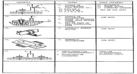
2 assumed that the user has knowledge of the system of loads acting on the joint in the vicinity of the fastener(s); these being derived by analysis of the overall structure prior to detailed consideration of joint design. Adequate definition of the applied loading system is essential as this may determine the particular category to which a joint belongs and hence the method of analysis adopted. This is particularly critical when distinguishing between concentric and eccentric axially loaded joints. The selection of the appropriate analysis for the combined loading case is also dependent on adequate specification of the loading system. More complex situations arise where combined loading occurs, typically axial, shear and bending. However, where a single load is dominant in a combined loading case and other load(s) are small it may be possible to assume the joint falls into one of the first three categories outlined below, thereby simplifying the analysis without significant reduction in accuracy. Criteria are included to determine when such an assumption is applicable Concentric Axially Loaded Joints The distinguishing feature of this joint category is that the line of action of the applied loading on the joint is parallel to and coincident with the longitudinal axis of the fastener. Therefore, any combination of joint geometry and system of applied loads which conform to this definition may be analysed by the methods and procedures specified for this category. Examples of joints for this category are illustrated in Figure1 to Figure3. For clarity a single fastener is shown, although in many cases the same analysis may be applied to a group of fastener if they are in a symmetric pattern. However, it should be noted that the effect of flange flexibility can lead to eccentric fastener loads in joints that with symmetric fastener pattern (see Figure3, Joint 17) Eccentric Axially Loaded Joints For this joint category the line of action of the applied loading on the joint, whilst being parallel to the fastener longitudinal axis, is not coincident, but offset. The result of this is that a prying (or prising ) action occurs between the clamped parts of the joint such that bending loads are introduced under the bolt head and in the shank. Three fundamental loading case variants can be identified depending on the relative position of the bolt axis, line of action of the applied load, and the joint centroid. This category of joint and its variants represent a large proportion of the joints encountered in practice. The main examples of these are illustrated in Figure1 to Figure3. For clarity a single fastener is shown, although in practice this may be a group Shear Loaded Joints The principle feature of this joint category is that the line of action of the applied loading on the joints is in the plane of the clamped parts immediately adjacent to the fastener, and therefore normal to the fastener longitudinal axis. The forces need not be coplanar if the joint is of the non-symmetrical or single lap shear type. Joints of this type may be further subdivided into friction grip or bearing categories, depending on whether load is transferred through the joint by friction at the faying surfaces or by transverse shear in the fastener(s). Examples of joints in this category are illustrated in Figure1 to Figure3. For clarity a single fastener is shown, although in practice this may be a group if the joint has multiple fasteners Combined Loaded Joints The essential feature of this joint category is that more than one system of loads act on the joint relative to the fastener axis. In the most general case features of all the preceding categories will be combined. Examples of joints for this category are illustrated in Figure1 to Figure3. For simplicity a single fastener can often be considered, although in practice the same may be a group if the joint has multiple fasteners. During the design process, joints initially being placed in the (most general) category of combined loaded joints may be reclassified into a sub-category, for the purpose of analysis. This guideline does not provide specific criteria for determining when this simplification can be assumed. Rather, the appropriate analysis method should be determined using engineering judgment considering the relative magnitudes of the shear and axial loads, the configuration of the joint and any other relevant attributes of the design Low Duty Joints Joints in this category have loadings and configurations that fit into one of the preceding categories, however they form a unique category since they have small external loading with respect to the fastener strength. In many cases this will be readily apparent due to the particular application, e.g. hold-downs, access panel attachments, etc. Some example diagrams of joints that frequently fall into this category are shown in Figure1 to Figure 3. 2 Page

3 Fig. 1 Fig.2 Fig.3 3 Page
4 II. Problem Statement 2.1 Practically very engineering product with every degree of complexity uses threaded fasteners a key advantage of threaded fasteners over the majority of other joining methods is that they can be disassembled and re used. This feature is often the reason why threaded fasteners are used in preference to other joining methods and they often pay a vital role in maintaining the products structural integrity. However, they are also a significant source of problems in machinery and other assembly s.the reasons for such problems are due in part to them unintentionally self -loosening. 2.2 The pre load is the initial clamp forces imparted into a joint by tighten a fastener. The vast majority of joints rely upon this pre load for their structural integrity.the pre load acts on the fastener threads creates a torque in the circumferential direction which is registered by friction. Self loosening of fasteners leads to a reduction and sometimes the elevation of this pre load which is frequently leads to joint failure. 2.3 Most bolted joints especially the ones associated with machinery, are subjected to significant vibration labels during their life span. Rotating or reciprocating machines such as gas, steam turbine, electric motors and IC engines are subjected to vibration of relatively high frequencies; gyratory crushers, jackhammers and so forth are subjected to medium frequencies vibration. III. Objectives 3.1The aim of this study is to find a constructive way to protect a bolted connection from self-loosening. 3.2To study the effect and design bolt to sustain for the vibrations. IV. Literature Review A. Nomesh Kumar, P.V.G. Brahamanandam and B.V. Papa Rao 3-D Finite Element Analysis of Bolted Flange Joint of Pressure Vessel In his paper it was studied that, the stresses in the bolts of the bolted flange joint of the pressure vessel so that bolts/studs should not be failed during proof pressure test. Bolted flange joints perform a very important structural role in the closure of flanges in a pressure vessel. It has two important functions: (a). to maintain the structural integrity of the joint itself, and (b). to prevent the leakage through the gasket preloaded by bolts. The preload on the bolts is extremely important for the successful performance of the joint. The preload must be sufficiently large to seat the gasket and at the same time not excessive enough to crush it. The flange stiffness in conjunction with the bolt preload provides the necessary surface and the compressive force to prevent the leakage of the gases contained in the pressure vessel. The gas pressure tends to reduce the bolt preload, which reduces gasket compression and tends to separate the flange faces. Due to flange opening, bending has been noticed in the bolt. Hence the bolts/studs should be designed to withstand against preload, internal pressure load and bending moment. Due to existence of Preload, internal pressure and bending moment at a time, the bolt behaviour is nonlinear which cannot not be evaluated by simple mathematical formulas. 3-Dimensional finite element analysis approach is only the technique which shows some satisfactory result. B. Gowri Srinivasan & Terry F. Lehnhoff Bolt Head Fillet Stress Concentration Factor Cylindrical Pressure Vessels In this paper it is found that, linear three-dimensional finite element analysis (FEA) was performed on bolted pressure vessel joints to determine maximum stresses and stress concentration factors in the bolt head fillet as a result of the prying action. The three-dimensional finite element models consisted of a segment of the flanges containing one bolt, using cyclic symmetry boundary conditions. The maximum stress in the bolt as well as the stress concentration factors in the bolt head fillet increase with an increase in bolt circle diameter for a given outer flange dimension. Keeping the bolt circle diameter constant, bolt stress and stress concentration factors inthe bolt head fillet decrease with increase in outer flange diameter. The maximum stresses in the bolt were also calculated according to the American Society of Mechanical Engineers (ASME) Boiler and Pressure Vessel Code and the Verein Deutscher Ingenieur (VDI) guidelines and compared to the results observed through finite element analysis. The stresses obtained through FEA were larger than those predicted by the ASME and VDI methods by a factor that ranged between 2.96 to 3.41 (ASME) and 2.76 to 3.63 (VDI). C. S.H. Ju, C.Y. Fan, & G.H. Wub 3-dimensional finite elements of steel bolted connections In this paper it was found that, the three-dimensional (3D) elasto-plastic finite element method is used to study the structural behaviour of the butt-type steel bolted joint. The numerical results are compared with 4 Page
5 AISC specification data. The similarity was found to be satisfactory despite the complication of stress and strain fields during the loading stages. When the steel reaches the nonlinear behaviour, the bolt nominal forces obtained from the finite element analyses are almost linearly proportional to the bolt number arranged in the connection. Moreover, the bolt failure is marginally dependent on the plate thickness that dominates the magnitude of the bending effect. For the cracked plate in a bolted-joint structure, the relationship between KI and the applied load is near linear, in which the nonlinear part is only about one tenth of the total relationship. This means that the linear elastic fracture mechanics can still be applied to the bolted joint problem for the major part of the loading, even through this problem reveals highly nonlinear structural behaviour. D. Iuliana PISCAN, Nicolae PREDINCEA & Nicolae POP FINITE ELEMENT ANALYSIS OF BOLTED JOINT In this paper it was found that, this paper presents a theoretical model and a simulation analysis of bolted joint deformations. The bolt pretension force, friction coefficient and contact stiffness factor are considered as parameters which are influencing the joint deformation. The bolted joint is modelled using CATIA software and imported in ANSYS WORKBENCH. The finite element analysis procedure required in ANSYS WORKBENCH simulation is presented as a predefined process to obtain accurate results. E. Ali Najafi, Mohit Garg and Frank Abdi Failure Analysis of Composite Bolted Joints in Tension In this paper it is found that, the failure of preloaded cross-ply laminated composite has been studied through finite element simulation embedded in Progressive Failure Analysis (PFA). Two modelling strategies including low- and high-fidelity models have been considered for this investigation. The high-fidelity FE model consists of fixture components (bolts and washers). It has been shown that both low- and high-fidelity FE models are capable of predicting the experimentally observed failure modes of bolted joints that depends on the geometric parameters with reasonable accuracy. Two catastrophic failure loads, net-tension and shear out can be predicted using both low- and high-fidelity model while the failure load of bearing mode can only be predicted via highfidelity model that considers the applied preload of the bolt. However, the overall stiffness in the actual experiment is lower than that of predicted via finite element simulation. F. ZHANG Yongjie and SUN Qin Joint Stiffness Analysis of Sheared Bolt with Preload In this paper it is found that, nonlinear contact arithmetic of ANSYS system is employed for simulating holeedge stress of sheared bolt. The preload of sheared bolt is caused by cool method. In this paper, an evaluation formula of bolt joint stiffness is presented to obtain relative curves between bolt joint stiffness and thickness of lapped plates. Some reliable conclusions are shown for simplifying computation of lapped bolt from complex structure. Bolted joints are probably the best choice to apply a desired clamp load to assemble a joint, with the option to disassemble if and when necessary [1]. The threaded fastener (nut and bolt) has played a significant role in the industrial revolution even though the exact date of its conception is not known. The concept of a helical thread was first introduced by Archimedes in the 3rd century B.C. Some archeologists argue that the threaded fastener was in existence even before Archimedes at the Hanging Gardens of Babylon. It is accepted that the common forms of threaded fastener assemblies have been in existence for at least 500 years [3]. History of evolution of screw fasteners dates back to few thousand years ago. It is learnt that screw fasteners were used in the Tigris Euphrates region in around 1,000 B.C., mainly, for the purpose of water supply. The plate shaped cross-section of the screw thread was then used. The People of Greece were also supposed to use screws to press olives. Leonardo da Vinci is credited for creating and sketching different ideas leading to implementation of important usage of screw threads [1]. This work includes the numerical studies in static analysis of single lap bolted joint. The model has been developed in the CAD software. Stress analysis has been carried out using finite element method. Static analysis is a multi-discipline Computer Aided Engineering (CAE) tool that analyzes the physical behavior of a model to better understand and improve the mechanical performance of a design[2]. It can be used to directly calculate stresses, deflections and thus to predict the behavior of the design in the real world. for analyzing the problem, various elements were modeled using Pro-Engineer 4.0. These solid models are imported in ANSYS workbench for meshing, and the meshed model was subjected to boundary condition as loads and constraints. Then a deck is generated for solver and template is solved using ANSYS workbench. 5 Page

 = 174mm")


6 V. Finite Element Analysis Plate=300x50x8mm & Eccentricity(e) = 174mm Fig.4- Material Properties Fig 4. Meshing of lap joint Fig.5 Boundry condition -Bolt Pretension Fig.6- Von Mises Stress and Total Deformation in whole Lap Joint 6 Page


7 Fig7-20 Directional Deformation in X Direction VI. Result Table.1-Result TABLE.2- ANALYTICALLY DETERMINED STRESSES FOR ALL MODELS UNDER ANALYSIS VII. Conclusion The discussion and conclusion on the basis of result is presented in this section. We are considering symmetrical model as solution basis because circular flange of turbine housing assembly shares the strength equally with respect to lap joint, hence symmetry is maintain. The experimental determination of breaking strength of symmetrical eccentric loaded bolted joint revealed the breaking stress is 253 MPa. The FE analysis of symmetrical eccentric loaded bolted joint for the same geometry revealed the maximum shear stress is in the range of 121 MPa to 227 MPa References Journal Papers: [1]. Vessel MIT International Journal of Mechanical Engineering, Vol. 1, No. 1, Jan 2011, pp [2]. Gowri Srinivasan and Terry F. Lehnhoff, Bolt Head Fillet Stress Concentration actors in Cylindrical Pressure Vessels Journal of Pressure Vessel Technology, Vol. 123, AUGUST 2001, pp [3]. S.H. Ju, C.Y. Fan and G.H. Wub, Three-dimensional finite elements of steel bolted connections Engineering Structures, Vol. 26, (2004), pp [4]. Iuliana Piscan, Nicolae Predincea, Nicolae Pop, Finite Element Analysis of Bolted Joints, Proceedings in Manufacturing Systems, Vol. 5, No. 3, 2010, pp Page
8 [5]. Ali Najafi, Mohit Garg, frank Abdi, Failure Analysis of composite Bolted Joints in Tension, 50th [6]AIAA/ASME/ASCE Structures, Structural Dynamics and material Conference, 4-7 May 2009, Palm Springs, California. AIAA [6]. ZHANG Yongjie and SUN Qin, Joint Stiffness Analysis of Sheared Bolt with Preload, Second International Conference on Intelligent Computation Technology and Automation, 2009, pp [7]. M.P. Cavatorta, D.S. Paolino, L. Peroni and M. Rodino, A finite element simulation and experimental validation of a composite bolted joint loaded in bending and torsion, Composites, Part A, Vol. 38, 2007, pp [8]. Qiwei Guo, Guoli Zhang and Jialu Li, Process parameters design of a three-dimensional and five-directional braided composite joint based on finite element analysis, Materials and Design, Vol. 46, Page
DESIGN AND OPTIMIZATION OF BOLTED JOINT SUBJECTED TO SHEAR AND BENDING LOAD
 DESIGN AND OPTIMIZATION OF BOLTED JOINT SUBJECTED TO SHEAR AND BENDING LOAD Khemchand M. Kapgate Dr. C. C. Handa V. D. Dhopte Mechanical Engineering Department Professor Assistant Professor K.D.K.C.E.
1/2/2016. Lecture Slides. Screws, Fasteners, and the Design of Nonpermanent Joints. Reasons for Non-permanent Fasteners
 Lecture Slides Screws, Fasteners, and the Design of Nonpermanent Joints Reasons for Non-permanent Fasteners Field assembly Disassembly Maintenance Adjustment 1 Introduction There are two distinct uses
Failure of Engineering Materials & Structures. Code 34. Bolted Joint s Relaxation Behavior: A FEA Study. Muhammad Abid and Saad Hussain
 Failure of Engineering Materials & Structures Code 3 UET TAXILA MECHNICAL ENGINEERING DEPARTMENT Bolted Joint s Relaxation Behavior: A FEA Study Muhammad Abid and Saad Hussain Faculty of Mechanical Engineering,
An Investigation of Optimal Pitch Selection to Reduce Self-Loosening of Threaded Fastener under Transverse Loading
 IJSTE - International Journal of Science Technology & Engineering Volume 3 Issue 01 July 2016 ISSN (online): 2349-784X An Investigation of Optimal Pitch Selection to Reduce Self-Loosening of Threaded Fastener
Finite Element Modeling of Early Stage Self-loosening of Bolted Joints Haoliang Xu 1, a, Lihua Yang 1, b,, Lie Yu 1,2, c
 International Conference on Information Sciences, Machinery, Materials and Energy (ICISMME 2015) Finite Element Modeling of Early Stage Self-loosening of Bolted Joints Haoliang Xu 1, a, Lihua Yang 1, b,,
Experimental And FE Analysis Of Eccentric Loaded Symmetrical And Unsymmetrical Bolted Joint With Bolt Pretension
 RESEARCH ARTICLE OPEN ACCESS Experimental And FE Analysis Of Eccentric Loaded Symmetrical And Unsymmetrical Bolted Joint With Bolt Pretension Pranav R. Pimpalkar*, Prof. S. D. Khamankar** *(P. G. student
Stress Analysis of Flanged Joint Using Finite Element Method
 Stress Analysis of Flanged Joint Using Finite Element Method Shivaji G. Chavan Assistant Professor, Mechanical Engineering Department, Finolex Academy of Management and Technology, Ratnagiri, Maharashtra,
3-D Finite Element Analysis of Bolted Joint Using Helical Thread Model
 3-D Finite Element Analysis of Bolted Joint Using Helical Thread Model Shaik Gousia Yasmin 1, P. Punna Rao 2, Kondaiah Bommisetty 3 1 M.Tech(CAD/CAM), Nimra College of Engineering & Technology, Vijayawada,
REVIEW OF THREADED FASTENERS LOOSENING AND ITS EFFECTS
 REVIEW OF THREADED FASTENERS LOOSENING AND ITS EFFECTS Mr. Kale Amol Scholar, M.E. Mechanical Design, V. V. P. Institute of Engineering and Technology, Solapur, India Prof. S. M. Shaikh A.P. Mechanical
SIMULATION AND EXPERIMENTAL WORK OF SINGLE LAP BOLTED JOINT TESTED IN BENDING
 SIMULATION AND EXPERIMENTAL WORK OF SINGLE LAP BOLTED JOINT TESTED IN BENDING Aidy Ali *, Ting Wei Yao, Nuraini Abdul Aziz, Muhammad Yunin Hassan and Barkawi Sahari Received: Jun 13, 2007; Revised: Nov
AN INNOVATIVE FEA METHODOLOGY FOR MODELING FASTENERS
 AN INNOVATIVE FEA METHODOLOGY FOR MODELING FASTENERS MacArthur L. Stewart 1 1 Assistant Professor, Mechanical Engineering Technology Department, Eastern Michigan University, MI, USA Abstract Abstract Researchers
Effect of Bolt Layout on the Mechanical Behavior of Four Bolted Shear Joint
 Effect of Bolt Layout on the Mechanical Behavior of Four Bolted Shear Joint using Three Dimensional Finite Effect of Bolt Layout on the Mechanical Behavior of Four Bolted Shear Joint using Three Dimensional
Modeling Multi-Bolted Systems
 Modeling Multi-Bolted Systems Jerome Montgomery Siemens Power Generation Abstract Modeling a single bolt in a finite element analysis raises questions of how much complexity to include. But, modeling a
1. Enumerate the most commonly used engineering materials and state some important properties and their engineering applications.
 Code No: R05310305 Set No. 1 III B.Tech I Semester Regular Examinations, November 2008 DESIGN OF MACHINE MEMBERS-I ( Common to Mechanical Engineering and Production Engineering) Time: 3 hours Max Marks:
An Alternative Formulation for Determining Stiffness of Members with Bolted Connections
 An Alternative Formulation for Determining Stiffness of Members with Bolted Connections Mr. B. Routh Post Graduate Student Department of Civil Engineering National Institute of Technology Agartala Agartala,
ABSTRACT II. OBJECTIVE I. INTRODUCTION III. METHODOLOGY
 2017 IJSRSET Volume 3 Issue 3 Print ISSN: 2395-1990 Online ISSN : 2394-4099 Themed Section: Engineering and Technology Analysis of Cylinder Head Bolt Cross Pattern Tightening and Its Effect on Gasket Sealing
A training course delivered at a company s facility by Matrix Engineering, an approved provider of Bolt Science Training
 A training course delivered at a company s facility by Matrix Engineering, an approved provider of Bolt Science Training Following is an outline of the material covered in the training course. Each person
DESIGN AND RELIABILITY INFLUENCES ON SELF-LOOSENING OF MULTI-BOLTED JOINTS
 Proceedings of the 5th International Conference on Integrity-Reliability-Failure, Porto/Portugal 24-28 July 2016 Editors J.F. Silva Gomes and S.A. Meguid Publ. INEGI/FEUP (2016) PAPER REF: 6302 DESIGN
Structural and Thermal Analysis of Bolted joint of Coiler Drum in Steckel Mill using Finite Element Method
 International Journal of Engineering Research and Development ISSN: 2278-067X, Volume 1, Issue 3 (June 2012), PP.63-69 www.ijerd.com Structural and Thermal Analysis of Bolted joint of Coiler Drum in Steckel
CH # 8. Two rectangular metal pieces, the aim is to join them
 CH # 8 Screws, Fasteners, and the Design of Non-permanent Joints Department of Mechanical Engineering King Saud University Two rectangular metal pieces, the aim is to join them How this can be done? Function
Bolt Material Types and Grades 1- Bolts made of carbon steel and alloy steel: 4.6, 4.8, 5.6, 5.8, 6.8, 8.8, 10.9 Nuts made of carbon steel and alloy
 Bolt Material Types and Grades 1- Bolts made of carbon steel and alloy steel: 4.6, 4.8, 5.6, 5.8, 6.8, 8.8, 10.9 Nuts made of carbon steel and alloy steel: 4, 5, 6, 8, 10, 12 2- Bolts made of stainless
A training course delivered at a company s facility by Matrix Engineering, an approved provider of Bolt Science Training
 A training course delivered at a company s facility by Matrix Engineering, an approved provider of Bolt Science Training Following is an outline of the material covered in the training course. Each person
Note: Conditions where bending loads are imposed on the bolt e.g. non-parallel bolting surfaces, should be avoided.
 Bolted Joint Design Introduction A most important factor is machine design, and structural design is the rigid fastening together of different components. This should include the following considerations..
Bolts and Set Screws Are they interchangeable?
 1903191HA Bolts and Set Screws Are they interchangeable? Prof. Saman Fernando Centre for Sustainable Infrastructure SUT Introduction: This technical note discusses the definitions, standards and variations
TORQUE DESIGN, ANALYSIS AND CHARACTERIZATION OF CRITICAL FASTENERS IN DIESEL ENGINES
 TORQUE DESIGN, ANALYSIS AND CHARACTERIZATION OF CRITICAL FASTENERS IN DIESEL ENGINES ROHIT PATIL 1, MUKUND NALAWADE 2, NITIN GOKHALE 3. 1 P.G. Student, Department of Mechanical Engineering, Vishwakarma
INFLUENCE OF PILES ON LOAD- SETTLEMENT BEHAVIOUR OF RAFT FOUNDATION
 INFLUENCE OF PILES ON LOAD- SETTLEMENT BEHAVIOUR OF RAFT FOUNDATION BALESHWAR SINGH Department of Civil Engineering Indian Institute of Technology Guwahati Guwahati 78139, India NINGOMBAM THOIBA SINGH
Joint relaxation behaviour of gasketed bolted flanged pipe joint during assembly
 Proceedings of the 2nd WSEAS Int. Conference on Applied and Theoretical Mechanics, Venice, Italy, November 20-22, 2006 319 Joint relaxation behaviour of gasketed bolted flanged pipe joint during assembly
Finite Element Analysis of Multi-Fastened Bolted Joint Connecting Composite Components in Aircraft Structures
 Finite Element Analysis of Multi-Fastened Bolted Joint Connecting Composite Components in Aircraft Structures Dr. M Satyanarayana Gupta Professor & HoD, Dept. of Aeronautical Engineering MLRIT, Hyderabad.
Mechanical joints. Major diameter Mean diameter Minor diameter Pitch p chamfer. Root Crest. Thread angle 2a. Dr. Salah Gasim Ahmed YIC 1
 Screw fasteners Helical threads screws are an extremely important mechanical invention. It is the basis of power screws (which change angular motion to linear motion) and threaded fasteners such as bolts,
DESIGN, ANALYSIS AND OPTIMIZATION OF CURVE ATTACHMENT ON COMPOSITE HYBRID LAP JOINT
 DESIGN, ANALYSIS AND OPTIMIZATION OF CURVE ATTACHMENT ON COMPOSITE HYBRID LAP JOINT S. Sridhar 1, S. Lakshmi Narayanan 2 1Master s in CAD/CAM Engineering, CIPET- Chennai, Govt. of India. 2Assistant Professor,
THE GATE COACHAll Rights Reserved 28, Jia Sarai N.Delhi ,-9998
 1 P a g e 1 DESIGN AGAINST STATIC AND FLUCTUATING LOADS 2 SHAFT, KEYS AND COUPLINGS CONTENTS Introduction 6 Factor of safety 6 Stress concentration 7 Stress concentration factors 8 Reduction of stress
Comparative Evaluation of Resistance Made Simple Shear Connection with Bolts and With Welding
 International Journal of Engineering Inventions e-issn: 78-7461, p-issn: 319-6491 Volume 3, Issue 7 (February 014) PP: 1-5 Comparative Evaluation of Resistance Made Simple Shear Connection with Bolts and
Hours / 100 Marks Seat No.
 17610 15116 4 Hours / 100 Seat No. Instructions (1) All Questions are Compulsory. (2) Answer each next main Question on a new page. (3) Illustrate your answers with neat sketches wherever necessary. (4)
Prying of a Large Span Base Plate Undergoing a Moment Load Applied by a Round Pier
 Prying of a Large Span Base Plate Undergoing a Moment Load Applied by a Round Pier by Anastasia Wickeler A thesis submitted in conformity with the requirements for the degree of Masters of Applied Science
A finite element stress analysis of aircraft bolted joints loaded in tension
 THE AERONAUTICAL JOURNAL JUNE 2010 VOLUME 114 NO 1156 A finite element stress analysis of aircraft bolted joints loaded in tension R.H. Oskouei reza.oskouei@eng.monash.edu.au Department of Mechanical and
DESIGN OF MACHINE MEMBERS-I
 Code No: R31035 R10 Set No: 1 JNT University Kakinada III B.Tech. I Semester Regular/Supplementary Examinations, Dec - 2014/Jan -2015 DESIGN OF MACHINE MEMBERS-I (Mechanical Engineering) Time: 3 Hours
Stress Analysis Of Bolted Joint
 Stress Analysis Of Bolted Joint Rashtrapal B. Teltumade Student of M.Tech (CAD/CAM), Rajiv Gandhi College Of Engineering, Research and Technology, Chandrapur(M.S.) Prof. Y. L. Yenarkar Associate Professor
Connection and Tension Member Design
 Connection and Tension Member Design Notation: A = area (net = with holes, bearing = in contact, etc...) Ae = effective net area found from the product of the net area An by the shear lag factor U Ab =
Pre stressed modal FE Analysis of bolted joint
 Pre stressed modal FE Analysis of bolted joint Prof. Kashinath.H.Munde 1, Mr. Mahesh P. Mestry 2 1,2 Mechanical Engg./ APCOER/ Pune University Abstract Threaded fasteners are one of the most common means
D DAVID PUBLISHING. Analysis of Leakage in Bolted-Flanged Joints Using Contact Finite Element Analysis. 1. Introduction.
 Journal of Mechanics Engineering and Automation 5 (2015) 135-142 doi: 10.17265/2159-5275/2015.03.001 D DAVID PUBLISHING Analysis of Leakage in Bolted-Flanged Joints Using Contact Finite Element Analysis
Power Threads. Shigley s Mechanical Engineering Design
 Power Threads Power screw Mechanics of Power Screws Used to change angular motion into linear motion Usually transmits power Examples include vises, presses, jacks, lead screw on lathe Fig. 8 4 Square
Bolt Tensioning. This document is a summary of...
 If you want to learn more about best practice machinery maintenance, or world class mechanical equipment maintenance and installation practices, follow the link to our Online Store and see the Training
Finite-Element-Analysis of Mechanical Characteristics of RTM-Tools
 Finite-Element-Analysis of Mechanical Characteristics of RTM-Tools Dipl.-Ing. (FH) N. Erler, Dr.-Ing. M. Lünemann, Dipl.-Ing. (FH) M. Ströher Airbus Deutschland GmbH Center of Competence Jigs and Tools
Numerical and Experimental Study of Shear Loaded Bolted Joint
 Research Article International Journal of Current Engineering and Technology ISSN 2277-4106 2013 INPRESSCO. All Rights Reserved. Available at http://inpressco.com/category/ijcet Numerical and Experimental
Development of a Numerical Technique for the Static Analysis of Bolted Joints by the FEM
 , July 3-5, 2013, London, U.K. Development of a Numerical Technique for the Static Analysis of Bolted Joints by the FEM D. Valladares, M. Carrera, L. Castejon, C. Martin Abstract The use of numerical simulation
A Study on Effect of Sizing Bolt Hole in Single-Lap Connection Using FEA
 Journal of Scientific Research & Reports 19(1): 1-14, 2018; Article no.jsrr.40498 ISSN: 2320-0227 A Study on Effect of Sizing Bolt Hole in Single-Lap Connection Using FEA Anil Zafer 1, Orkun Yilmaz 1*
Fig. (8.1) types of riveted joints
 types of riveted joints") 8 Riveted Joints 8. Introduction Riveting was the standard method of joining plates and structural parts before welding began to replace it with increasing rapidity. are widely used in many engineering
8 Riveted Joints 8. Introduction Riveting was the standard method of joining plates and structural parts before welding began to replace it with increasing rapidity. are widely used in many engineering
UNIVERSITY OF THESSALY
 UNIVERSITY OF THESSALY MECHANICAL ENGINEERING DEPARTMENT Instructor: Dr. S.D. Chouliara e-mail: schoul@uth.gr MACHINE ELEMENTS Task 2 1. Let the bolt in the following Figure be made from cold-drawn steel.
The Stamina of Non-Gasketed, Flanged Pipe Connections
 The Stamina of Non-Gasketed, Flanged Pipe Connections M. Abid 1, D. H. Nash 1 and J. Webjorn 2 Most international design codes for pressure equipment, such as BS 5500, ASME VIII and the new European standard
Bhagwan mahavir college of Engineering & Technology, Surat.
 Bhagwan mahavir college of Engineering & Technology, Surat. Department of automobile Engineering Assignment Subject: Machine Design & Industrial Drafting B.E. Second year Instructions: 1. This set of tutorial
0.20. Record Page 1 of 19
 Page 1 of 19 Page 2 of 19 Page 3 of 19 Page 4 of 19 Page 5 of 19 ASME BPVC.III.1.ND-2015 Page 6 of 19 ð15þ Figure ND-3325-1 Some Acceptable Types of Unstayed Flat Heads and Covers GENERAL NOTE: The illustrations
TECH SHEET PEM - REF / THREAD GALLING. SUBJECT: Root causes and guidelines to promote optimized fastener performance TECH SHEET
 PEM - REF / THREAD GALLING SUBJECT: Root causes and guidelines to promote optimized fastener performance Introduction Occasionally, users of our self-clinching fasteners encounter thread binding issues
Bolted Joint Design. Mechanical Properties of Steel Fasteners in Service
 Bolted Joint Design There is no one fastener material that is right for every environment. Selecting the right fastener material from the vast array of those available can be a daunting task. Careful consideration
Design of Machine Elements I Prof. G. Chakraborty Department of Mechanical Engineering Indian Institute of Technology Kharagpur
 Design of Machine Elements I Prof. G. Chakraborty Department of Mechanical Engineering Indian Institute of Technology Kharagpur Lecture - 22 Rivet Joints Dear student, welcome to the video lectures on
Threaded Fasteners 2. Shigley s Mechanical Engineering Design
 Threaded Fasteners 2 Bolted Joint Stiffnesses During bolt preload bolt is stretched members in grip are compressed When external load P is applied Bolt stretches further Members in grip uncompress some
THE INFLUENCE OF GEOMETRIC PARAMETERS AND MECHANICAL PROPERTIES OF ADHESIVE ON STRESS ANALYSIS IN ADHESIVELY BONDED ALUMINUM SINGLE LAP JOINT
 Mojtaba Samaei Mostafa Seifan Amir Afkar Amin Paykani ISSN 333-24 eissn 849-39 THE INFLUENCE OF GEOMETRIC PARAMETERS AND MECHANICAL PROPERTIES OF ADHESIVE ON STRESS ANALYSIS IN ADHESIVELY BONDED ALUMINUM
MECH 344/M Machine Element Design
 1 MECH 344/M Machine Element Design Time: M 14:45-17:30 Lecture 6 Contents of today's lecture Introduction Multitude of fasteners are available raging from nuts and bots to different varieties. Only a
Design of structural connections for precast concrete buildings
 BE2008 Encontro Nacional Betão Estrutural 2008 Guimarães 5, 6, 7 de Novembro de 2008 Design of structural connections for precast concrete buildings Björn Engström 1 ABSTRACT A proper design of structural
STUDY AND ANALYSIS OF ANGULAR TORQUING OF ENGINE CYLINDER-HEAD BOLTS USING TORQUE-TO-YIELD BOLTS: A CASE STUDY
 International Journal of Mechanical and Production Engineering Research and Development (IJMPERD) ISSN 2249-6890 Vol. 3, Issue 4, Oct 2013, 1-10 TJPRC Pvt. Ltd. STUDY AND ANALYSIS OF ANGULAR TORQUING OF
Hanger bolts and solar fasteners in sandwich panels
 Hanger bolts and solar fasteners in sandwich panels Helmut Krüger 1, Thomas Ummenhofer 2, Daniel C. Ruff 3 Abstract For the energetic use of sunlit roofs, photovoltaic and solar thermal elements are mounted
UNDERSTANDING TORQUE -ANGLE SIGNATURES OF BOLTED JOINTS
 SENSORS FOR RESEARCH & DEVELOPMENT WHITE PAPER #23 UNDERSTANDING TORQUE -ANGLE SIGNATURES OF BOLTED JOINTS THREADED FASTENER TORQUE-ANGLE CURVE ANALYSIS Written By Jeff Drumheller www.pcb.com info@pcb.com
Welded connections Welded connections are basically the same design in AISI as in AISC. Minor differences are present and outlined below.
 Cold-Formed Steel Design for the Student E. CONNECTIONS AND JOINTS E1 General Provisions Connections shall be designed to transmit the maximum design forces acting on the connected members. Proper regard
A training course delivered to Engineers and Designers, at a company s premises, on the technical aspects of bolting.
 A training course delivered to Engineers and Designers, at a company s premises, on the technical aspects of bolting. Consulting Analysis Services Software Training An outline is presented below of the
ERECTION & CONSTRUCTION
 ERECTION & CONSTRUCTION High Strength Structural Bolting Author: Clark Hyland Affiliation: Steel Construction New Zealand Inc. Date: 24 th August 2007 Ref.: Key Words High Strength Bolts; Property Class
Stress Analysis of Bolts Failure in Flange Joint of Coiler Drum in Steckel Furnace by Using Fem Methods
 Stress Analysis of Bolts Failure in Flange Joint of Coiler Drum in Steckel Furnace by Using Fem Methods P. N. Awachat 1, V.K. Parate 2, S.S. Jane 3 1 Assistant Professor, Department of mechanical engineering
BOLTCALC Program. problems. User Guide. Software for the Analysis of Bolted Joints
 User Guide BOLTCALC Program Software for the Analysis of Bolted Joints problems BOLTCALC is produced by Bolt Science Limited Bolt Science provides analytical solutions to bolting problems www.boltscience.com
DETERMINATION OF JOINT DIAGRAMS FOR A FOUNDATION BOLTED JOINT WITH THE BOLT ANCHORED IN A POLYMER PLASTIC
 COMMITTEE OF MECHANICAL ENGINEERING PAS POZNAN DIVISION Vol. 32 no. 3 Archives of Mechanical Technology and Automation 2012 PAWE GRUDZI SKI DETERMINATION OF JOINT DIAGRAMS FOR A FOUNDATION BOLTED JOINT
NUMERICAL ANALYSIS OF SCREW ANCHOR FOR CONCRETE
 VIII International Conference on Fracture Mechanics of Concrete and Concrete Structures FraMCoS-8 J.G.M. Van Mier, G. Ruiz, C. Andrade, R.C. Yu and X.X. Zhang (Eds) NUMERICAL ANALYSIS OF SCREW ANCHOR FOR
Fastener Modeling for Joining Parts Modeled by Shell and Solid Elements
 2007-08 Fastener Modeling for Joining Parts Modeled by Shell and Solid Elements Aleander Rutman, Chris Boshers Spirit AeroSystems Larry Pearce, John Parady MSC.Software Corporation 2007 Americas Virtual
Experimental Evaluation of Metal Composite Multi Bolt Radial Joint on Laminate Level, under uni Axial Tensile Loading
 RESEARCH ARTICLE OPEN ACCESS Experimental Evaluation of Metal Composite Multi Bolt Radial Joint on Laminate Level, under uni Axial Tensile Loading C Sharada Prabhakar *, P Rameshbabu** *Scientist, Advanced
ISO INTERNATIONAL STANDARD. Fasteners Torque/clamp force testing. Éléments de fixation Essais couple/tension. First edition
 Provläsningsexemplar / Preview INTERNATIONAL STANDARD ISO 16047 First edition 2005-02-01 Fasteners Torque/clamp force testing Éléments de fixation Essais couple/tension Reference number ISO 16047:2005(E)
Instruction Manual for installing
 Instruction Manual for installing Preloaded (HSFG) Bolting with TurnaSure DIRECT TENSION INDICATORS CE Marked EN 14399-9 TurnaSure LLC TABLE OF CONTENTS Introduction... 1 Theory of Preloaded Bolting Assemblies...
Evaluation of In-Pavement Light Fixture Designs and Performance
 Evaluation of In-Pavement Light Fixture Designs and Performance Presented to: IES ALC Fall Technology Meeting By: Joseph Breen Date: Background In-Pavement Light Fixture Assemblies Utilize a Circle of
Studies on free vibration of FRP aircraft Instruments panel boards
 89 Studies on free vibration of FRP aircraft Instruments panel boards E. Chandrasekaran Professor in Dept. of Civil Engineering, Crescent Engineering College 648 India. e-mail: sekharan@vsnl.net and K.
Design and Analysis of Spindle for Oil Country Lathe
 Design and Analysis of Spindle for Oil Country Lathe Maikel Raj K 1, Dr. Soma V Chetty 2 P.G. Student, Department of Mechanical Engineering, Kuppam Engineering College, Kuppam, Chittoor, India 1 Principal,
MECHANICAL ASSEMBLY John Wiley & Sons, Inc. M. P. Groover, Fundamentals of Modern Manufacturing 2/e
 MECHANICAL ASSEMBLY Threaded Fasteners Rivets and Eyelets Assembly Methods Based on Interference Fits Other Mechanical Fastening Methods Molding Inserts and Integral Fasteners Design for Assembly Mechanical
Mechanical behavior of fiberglass reinforced timber joints
 Mechanical behavior of fiberglass reinforced timber joints Chen, Chi-Jen 1 ABSTRACT The objective of this research is to investigate the mechanical performance of dowel-type timber joints reinforced by
THIN-WALLED HOLLOW BOLTS
 THIN-WALLED HOLLOW BOLTS Experimental and numerical study Teixeira, C. D. S. Department of Mechanical Engineering, Instituto Superior Técnico, Av. Rovisco Pais, 1049-001, Lisbon, Portugal, 2010 Abstract
Comparative structural Analysis of Acme and Square Thread Screw jack
 Comparative structural Analysis of Acme and Square Thread Screw jack Prof. Dayanand D. More 1 1 Assistant Professor, Department of Mechanical Engineering New Horizon Institute of Technology and Management,
Model Correlation of Dynamic Non-linear Bearing Behavior in a Generator
 Model Correlation of Dynamic Non-linear Bearing Behavior in a Generator Dean Ford, Greg Holbrook, Steve Shields and Kevin Whitacre Delphi Automotive Systems, Energy & Chassis Systems Abstract Efforts to
CHAPTER 2 ELECTROMAGNETIC FORCE AND DEFORMATION
 18 CHAPTER 2 ELECTROMAGNETIC FORCE AND DEFORMATION 2.1 INTRODUCTION Transformers are subjected to a variety of electrical, mechanical and thermal stresses during normal life time and they fail when these
Instruction Manual for installing
 Instruction Manual for installing Preloaded (HSFG) Bolting with TurnaSure DIRECT TENSION INDICATORS TurnaSure LLC TABLE OF CONTENTS Introduction... 1 Theory of Preloaded Bolting Assemblies... 2 Tightening
Experimental and Finite Element Analysis of Preloaded Bolted Joints Under Impact Loading
 Mechanical Engineering Faculty Publications Mechanical Engineering 5-1-2006 Experimental and Finite Element Analysis of Preloaded Bolted Joints Under Impact Loading Brendan O'Toole University of Nevada,
Stress Analysis of T-Flange Bolted Joint with a Simplified Spring and Beam Model
 Ann. Rep. Fac. Educ., Iwate Univ., Vol.51 No.2 (Feb.1992) 65 `73 Stress Analysis of T-Flange Bolted Joint with a Simplified Spring and Beam Model Minoru TANAKA*, Takashi SASAKI**, Satoru HOSHINO***, and
Fatigue Analysis of VMC 450 Spindle
 Fatigue Analysis of VMC 450 Spindle Tushar Gadekar 1, Avinash Ranaware 2, Sonal Sawant 3 1Assistant Professor, Mechanical Engg Department, College of Engineering, Phaltan, Maharashtra, India 2Assistant
Advanced Dimensional Management LLC
 Index: Mechanical Tolerance Stackup and Analysis Bryan R. Fischer Accuracy and precision 8-9 Advanced Dimensional Management 14, 21, 78, 118, 208, 251, 286, 329-366 Ambiguity 4, 8-14 ASME B89 48 ASME Y14.5M-1994
TRANSVERSE FATIGUE CHARACTERISTICS OF BOLTED JOINTS TIGHTENED THIN PLATES
 Proceedings of the 7th International Conference on Mechanics and Materials in Design, Albufeira/Portugal 11-15 June 2017. Editors J.F. Silva Gomes and S.A. Meguid. Publ. INEGI/FEUP (2017) PAPER REF: 6846
LOAD CARRYING CAPACITY OF METAL DOWEL TYPE CONNECTIONS OF TIMBER STRUCTURES
 Vol. 10, Issue /014, 51-60 DOI: 10.478/cee-014-0011 LOAD CARRYING CAPACITY OF METAL DOWEL TYPE CONNECTIONS OF TIMBER STRUCTURES Jozef GOCÁL 1,* 1 Department of Structures and Bridges, Faculty of Civil
DESIGN AND FATIGUE ANALYSIS OF CHOKE VALVE BODY
 DESIGN AND FATIGUE ANALYSIS OF CHOKE VALVE BODY N. SURESH 1, B. SRINIVASA REDDY 2 Assistant professor, Geethanjali College of Engineering and technology, Cheeryal, Hyderabad, TS, India. ABSTRACT Design
c. Pins, bolts, and retaining rings b. Washers, locking nuts, and rivets
 62 20 HW 8: Fasteners / Force, Pressure, Density Mechanical Systems DUE Mon, 11/21/16 Start of class Check link on website for helpful fastener information Please use a scantron. Material is based primarily
Fluid Sealing Association
 Fluid Sealing Association STANDARD FSA-MG-501-02 STANDARD TEST METHOD FOR INWARD BUCKLING OF SPIRAL-WOUND GASKETS 994 Old Eagle School Road, Suite 1019 Wayne, Pennsylvania 19087-1866 Phone: (610) 971-4850
Hazlan Abdul Hamid* & Mohammad Iqbal Shah Harsad
 Malaysian Journal of Civil Engineering 28(1):59-68 (2016) BEHAVIOUR OF SELF-DRILLING SCREW UPON SINGLE SHEAR LOADING ON COLD FORMED STEEL Hazlan Abdul Hamid* & Mohammad Iqbal Shah Harsad Faculty of Civil
Modelling of Rebar and Cable Bolt Behaviour in Tension/Shear
 University of Wollongong Research Online Coal Operators' Conference Faculty of Engineering and Information Sciences 2015 Modelling of Rebar and Cable Bolt Behaviour in Tension/Shear Xuwei Li University
3D Non-Linear FEA to Determine Burst and Collapse Capacity of Eccentrically Worn Casing
 3D Non-Linear FEA to Determine Burst and Collapse Capacity of Eccentrically Worn Casing Mark Haning Asst. Prof James Doherty Civil and Resource Engineering, University of Western Australia Andrew House
ENGINEERING FUNDAMENTALS
 SENSORS FOR RESEARCH & DEVELOPMENT WHITE PAPER #20 ENGINEERING FUNDAMENTALS OF THREADED FASTENER DESIGN AND ANALYSIS Written By Ralph S. Shoberg www.pcb.com info@pcb.com 800.828.8840 MTS SYSTEMS CORPORATION
TECH SHEET PEM - REF / TESTING CLINCH PERFORMANCE. SUBJECT: Testing clinch performance of self-clinching fasteners.
 PEM - REF / TESTING CLINCH PERFORMANCE SUBJECT: Testing clinch performance of self-clinching fasteners. A self-clinching fastener s performance can be divided into two major types. The first is self-clinching
Tex-452-A, Rotational Capacity Testing of Fasteners Using a Tension Measuring Device
 Using a Tension Measuring Device Contents: Section 1 Overview...2 Section 2 Definitions...3 Section 3 Apparatus...4 Section 4 Part I, Rotational Capacity Testing...5 Section 5 Part II, Values for Fasteners
Fasteners. Fastener. Chapter 18
 Fasteners Chapter 18 Material taken from Mott, 2003, Machine Elements in Mechanical Design Fastener A fastener is any device used to connect or join two or more components. The most common are threaded
Design, Development and Analysis of Clamping Force of a Cylinder of Fixture for Casing of Differential
 Design, Development and Analysis of Clamping of a Cylinder of Fixture for Casing of Differential R.Akshay 1, Dr.B.N.Ravikumar 2 1PG Student, Department of Mechanical Engineering Bangalore Institute of
INFLUENCE OF SOME MODIFICATIONS OF LOCAL GEOMETRY ON THE STRESS STATES IN ADHESIVE BONDED LAP JOINTS
 SISOM 2009 and Session of the Commission of Acoustics, Bucharest 28-29 May INFLUENCE OF SOME MODIFICATIONS OF LOCAL GEOMETRY ON THE STRESS STATES IN ADHESIVE BONDED LAP JOINTS Adriana SANDU *, Marin SANDU