MECH 344/M Machine Element Design
|
|
|
- Ariel Cook
- 5 years ago
- Views:
Transcription
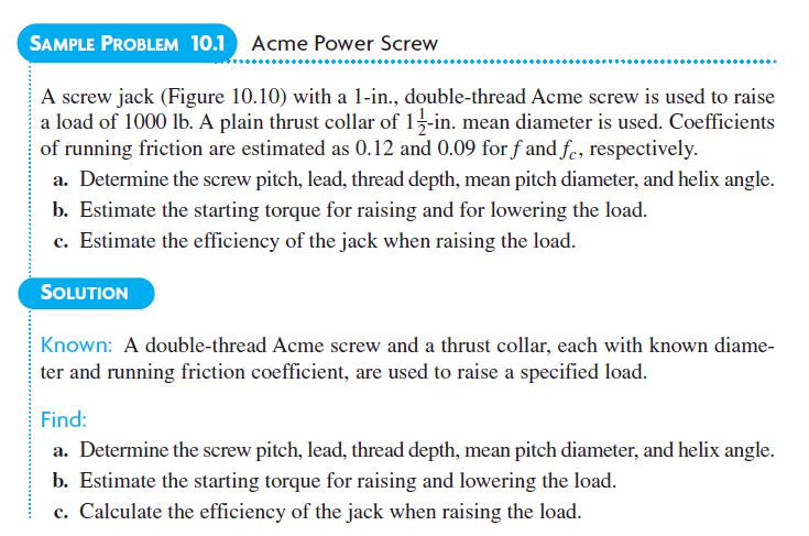
1 1 MECH 344/M Machine Element Design Time: M 14:45-17:30 Lecture 6

2 Contents of today's lecture
.")
3 Introduction Multitude of fasteners are available raging from nuts and bots to different varieties. Only a small sample is shown here Limit our discussion to design and selection of conventional fasteners (screws, nuts & bolts). Primarily used in machine design applications and lot of stresses are encountered. Used primarily for holding, or moving (lead screw) Loads are tensile, or shear or both The economic implications are tremendous. the airframe of a large jet aircraft has approximately 2.4 Million fasteners costing about $750,000 in 1978 dollars.
4 Figure 10.1 illustrates the basic arrangement of a helical thread wound around a cylinder, as used on screw-type fasteners, power screws, and worms. Pitch, lead, lead angle, and hand-of-thread are defined by the illustrations. Virtually all bolts and screws have a single thread, but worms and power screws sometimes have double, triple, and even quadruple threads. Unless otherwise noted, all threads are assumed to be right-hand.
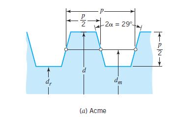
5 Figure 10.2 shows the standard geometry of screw threads used on fasteners. This is basically the same for both Unified (inch) and ISO (metric) threads. Standard sizes for the two systems are given in Tables 10.1 and The pitch diameter, d p, is the diameter of a cylinder on a perfect thread where the width of the thread and groove are equal. The stress area tabulated is based on the average of the pitch and root diameters. This is the area used for P/A stress calculations. It approximates the smallest possible fracture area, considering the presence of the helical thread.
6
7
8


9 Standard form of power screws Acme is the oldest. Acme stub is easier to heat treat Square gives more efficiency but 0 angle difficult Modified square with 5 is commonly used Buttress is used to resist large axial force in one direction For power screws with multiple threads, the number of threads per inch is defined as the reciprocal of the pitch, not the reciprocal of the lead.


10 An example: let's say you have a 1/2"-8 X 6' with 2 starts. The 1/2" is the diameter and the 8 is the threads per inch, but the difference here is the number of starts. The actual "turns per inch" is actually 4, not 8.
11

12 Nut turned with applied torque of T lifts load P To compensate for the friction between nut and the base, thrust bearings are used Another application is shown below For accurate positioning of the nut, based on rotation of the lead screw by servomotor

13 shaded member connected to the handle rotates, and that a ball thrust bearing transfers the axial force from the rotating to a nonrotating member. All 3 jacks being same, Figure 10.5c for determining the torque, Fa, that must be applied to the nut in order to lift a given weight. Turning the nut in Figure 10.5c forces each portion of the nut thread to climb an inclined plane.

14 Turning the nut forces each portion of the nut thread to climb an inclined plane. If a full turn were developed, a triangle would be formed, illustrating tan A segment of the nut is represented by the small block acted upon by load w, normal force n, friction force fn, and tangential force q. force q times d m /2 represents the torque applied to the nut segment.
15 Summing the tangential forces. Summing the axial forces With torque for q being q(d m /2) and q, n, w are acting on a small segment of the nut, integrating this to full nut and changing the notations to Q, N, W, the torque T required to lift a load W is
 is used friction adds to the torque required If the coefficient of friction of the collar washer or bearing is f c then For a")
16 Since L is more commonly referred to in threads than, dividing the numerator and denominator by cos and then substituting L/ dm for tan. Since a bearing or thrust washer (dia d c ) is used friction adds to the torque required If the coefficient of friction of the collar washer or bearing is f c then For a square thread, this simplifies to
17 For lowering the load, the directions of q and fn are reversed giving For a square thread, this simplifies to f c can be (because very low) neglected if ball or roller thrust bearing is used and the second portion of the term does not come into play f & f c can vary between.08 to.2 if plain thrust collar is used (if roller bearing used, f c can be neglected). This range includes both starting and running friction, with starting friction being 1 and 1/3 rd higher than running friction
18 Self locking implies positive torque to lower the load Neglecting collar friction, screw can be self locking if T>=0 For square threads
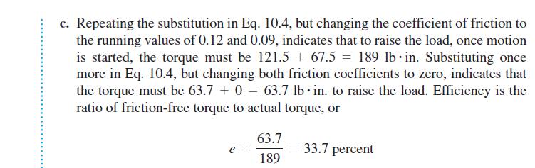
19 Work output divided by work input is the efficiency Work output in 1 revolution is load times distance which is WL Work input is the torque in one revolution which is 2 T So efficiency e = WL/ 2 T For a square thread Simplified to for square threads


20 As f increases; e lowers Efficiency tends to 0 as lead angle approaches 0, as load does not move much in the vertical plane Efficiency tends to 0 as lead angle approaches 90, as the plane more perpendicular and requires a lot of torque to move the object even slightly Ball bearing screws reduce f
21
22
23
24
25
. If the screw or bolt is hollow, where d i represents the inside diameter.")
26 For power screws and threaded fasteners the stress are Torsion while tightening where d is root diameter, d r, obtained from Figure 10.4 (for power screws) or Tables 10.1 and 10.2 (for threaded fasteners). If the screw or bolt is hollow, where d i represents the inside diameter. Where collar friction is negligible, the torque transmitted through a power screw is the full applied torque. With threaded fasteners, the equivalent of substantial collar friction is normally present, in which case it is customary to assume that the torque transmitted through the threaded section is approximately half the wrench torque.
27 Power screws are subjected to direct P/A tensile and compressive stresses; threaded fasteners are normally subjected only to tension. The effective area for fasteners is the tensile stress area A t (Table 10.1 & 10.2). For power screws axial stresses are not critical; so A t, approximated based on d r Threaded fasteners should always have enough ductility to permit local yielding at thread roots without damage. So non uniform load distribution is ok for static stresses. But not fatigue. The combination of the stresses can be the distortion energy theory used as a criterion for yielding. With threaded fasteners, it is normal for some yielding to occur at the thread roots during initial tightening.
28 Figure shows force flow through bolt & nut Compression between the threads exists at threads numbered 1, 2, and 3. This type of direct compression is often called bearing, and the area used for P/A stress calculation is the projected area that, for each thread, is (d 2 - d i2 )/4. The number of threads in contact is seen from the figure to be t/p. Diameter d i is the minor diameter of the internal thread. For threaded fasteners this can be approximated by d r, (Table 10.1)
29 Equation gives an average value of bearing stress. Not uniformly distributed due to threads bending and manufacturing variations from the theoretical geometry. Figure reveals two important factors causing thread 1 to carry more than its share of the load: 1. The load is shared among the 3 threads as redundant load-carrying members. The shortest (and stiffest) path is through The applied load causes the threaded portion of the bolt to be in tension, whereas the mating portion of the nut is in compression. The resulting deflections slightly increase bolt pitch and decrease nut pitch. This tends to relieve the pressure on threads 2 and 3.

30 To obtain nearly equal distribution of loads among the threads in contact, especially when considering fatigue loading is done by: 1. Make nut softer than bolt so that the highly loaded first thread will deflect, transferring the load to the other threads. Maybe increase the number of threads in contact in order to maintain strength. 2. Make Nut Pitch > bolt pitch so that the two pitches are equal after the load is applied. Mfg precision important to make sure that the nut and bolt can be readily assembled 3. Modifying the nut design as shown in Figure Here, the nut loading puts the region of the top threads in tension, thus causing elastic changes in pitch that approximately match the changes in bolt pitch. Such special nuts are expensive and have been used only in critical applications involving fatigue loading.
31 With reference to Figure 10.11, if the nut is weaker than bolt in shear (common), a sufficient overload would strip the nut threads along cylindrical surface A. If the bolt is weaker in shear, the failure surface would be B. From the thread geometry shown in Figure 10.2, the shear area is = d (0.75t), where d is the diameter of the shear fracture surface.
32 With reference to Figure 10.11, if the nut is weaker than bolt in shear (common), a sufficient overload would strip the nut threads along cylindrical surface A. If the bolt is weaker in shear, the failure surface would be B. From the thread geometry shown in Figure 10.2, the shear area is = d (0.75t), where d is the diameter of the shear fracture surface. The nut thickness (or depth of engagement in a tapped hole) needed to provide a balance between bolt tensile strength and thread stripping strength if bolt and nut strength are same. The bolt tensile force required to yield the entire threaded cross section is d is the major dia of the thread
33 With reference to Figure 10.11, the bolt tensile load required to yield the entire thread-stripping failure surface of the nut based on parabolic stress distribution is where t is the nut thickness. F bolt = F nut indicates bolt tensile and threadstripping strengths are balanced when the nut thickness is approximately Nuts are usually softer than bolts to allow slight yielding of top thread(s) and thus distribute the load more uniformly, the standard nut thickness is approximately t = 7/8 d or.875d
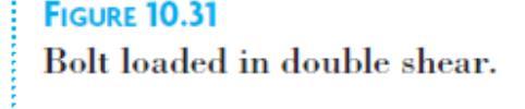
 Shear loads are transmitted by friction, where friction load-carrying capacity is = bolt tension X")

34 Bolts are sometimes subjected to transverse shear loading fig (4.3, 4.4) Shear loads are transmitted by friction, where friction load-carrying capacity is = bolt tension X clamped interface coeff of friction For the double shear, the friction load capacity would be twice this amount. Sometimes bolts are required to provide precise alignment of mating members and are made with a pilot surface as shown in Figure

35 Long power screws loaded in compression must be designed for buckling. It is important first to make sure that it is necessary to subject the screws to compression or a simple redesign allows it to be in tension Often, a simple redesign permits the screws to be in tension. For example, Figure 10.14a shows a press with the screws in compression. Figure 10.14b shows an alternative design with the screws in tension. The second is obviously to be preferred.

36 Classified based on intended use, thread type, head style, strength Based on intended use Blots - Used with a nut for assembly Machine screws - Or cap screw, threads into a tapped hole ANSI definition - bolt is stationary while nut engages. But screw engages in a tapped hole Studs - Headless fastener threaded on both ends
37
38 Need for screws that are resistant to tampering by unauthorized personnel An almost endless number of special threaded fastener designs continue to appear. Some are specially designed for a specific application. Others embody proprietary features that appeal to a segment of the fastener market. Not only is ingenuity required to devise better threaded fasteners, but also to use them to best advantage in the design of a product.


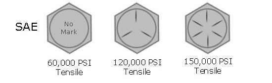
39 Mostly made of steel Specifications standardized as in tables 10.4 and 10.5 Aluminum is also common Rolled threads are stronger than cut threads and in case of higher loads, rolled threads should be used
40
41
42 Screws and nut-bolt assemblies should ideally be tightened with an initial tensile force F i nearly = full proof load, which is the maximum tensile force that does not produce a normally measurable permanent set. (This is < the tensile force producing a 0.2 percent offset elongation associated with S y ) On this basis initial tensions are specified in accordance with the equation where A t is the tensile stress area of the thread, S p is the proof strength of the material (Tables 10.4 and 10.5), and K i is a constant (0.75 to 1.0). For ordinary applications involving static loading, let K i 0.9, or 1. For loads tending to separate rigid members, the bolt load cannot be increased very much unless the members do actually separate, and the higher the initial bolt tension, the less likely the members are to separate. 2. For loads tending to shear the bolt, the higher the initial tension the greater the friction forces resisting the relative motion in shear.

43 Tightening of a imparts torsional stress to bolt, along with the initial tensile stress. During initial use, the bolt usually unwinds very slightly, relieving most of torsion.
 The most common method of tightening a bolt a measured amount is probably to use a")
44 the initial tension that can be achieved with a given bolt the amount of elongation that can be achieved before over tightening fractures the bolt. Accurate determination of bolt tensile load during tightening is difficult (micrometer or drilling and strain guage) The most common method of tightening a bolt a measured amount is probably to use a torque wrench. Accuracy limited. Normal torque wrench controls initial tension within ±30%; with special care, ± 15% is reasonable.
45 An equation relating torque to initial tension can be from Eq by recognizing that load W of a screw jack as to F i for a bolt, and that collar friction in the jack as friction on the flat surface of the nut. When we use 0.15 for both f and f c, in Eq. 10.4, for standard screw threads, where d is the nominal major diameter of the thread. This is approximate relationship, on average conditions of thread friction. A common way to tighten a screw or nut is While the tension increases with d 2 and torsion with d 3 the F i is dependent on d; So small bolts twist and large bolts remain undertightened When rigid parts are bolted, the elastic deflection of the parts <.01mm. Should the loading cause any creep, much of the bolt initial tension will be lost. 5% lost in first few minutes and another 5% lost in next few weeks
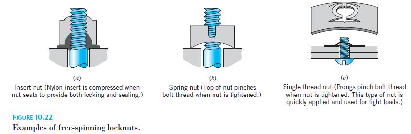
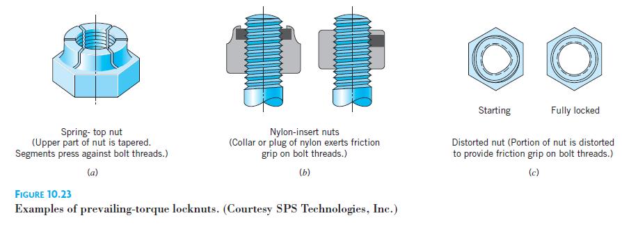
46 The following are among the factors influencing whether or not threads loosen. 1. The greater the helix angle (i.e., the greater the slope of the inclined plane), the greater the loosening tendency. Thus, coarse threads tend to loosen more easily than fine threads. 2. The greater the initial tightening, the greater the frictional force that must be overcome to initiate loosening. 3. Soft or rough clamping surfaces tend to promote slight plastic flow which decreases the initial tightening tension and thus promotes loosening. 4. Surface treatments and conditions that tend to increase the friction coefficient provide increased resistance to loosening. The problem of thread loosening has resulted in numerous and ingenious special designs and design modifications, and it continues to challenge the engineer to find effective and inexpensive solutions.
47
48
49 Bolts are typically used to hold parts together against to forces that pull, or slide Figure 10.24a shows the general case with external force F e tending to separate Figure 10.24b shows a portion of this assembly as a free body. In this figure the nut has been tightened, but the external force has not yet been applied. The bolt axial load F b = clamping force F c = initial tightening force F i. Figure 10.24c shows after F e has been applied. Equilibrium considerations require one or both of the following: 1. an increase in F b 2. a decrease in F c. The relative magnitudes of the changes in F b and F c depend on the relative elasticities involved.
50 Figure 10.25a shows a plate bolted on a pressure vessel with soft gasket so soft that the other parts can be considered infinitely rigid in comparison. When the nut is tightened to produce initial force F i, the rubber gasket compresses; the bolt elongates negligibly. Figures 10.25b and 10.25c show details of the bolt and the clamped surfaces. Note the distance defined as the grip g. On initial tightening, F b = F c = F i. Figure 10.25d shows the change in F b and F c as separating load F e is applied. The elastic stretch of the bolt caused by F e is so small. The clamping force F c does not diminish and the entire load F e goes to increasing bolt tension
. Figure 10.")
51 Figure illustrates the clamped members are rigid with precision-ground mating surfaces and no gasket, The bolt has a center portion made of rubber. Here the initial tightening stretches the bolt; it does not significantly compress the clamped members. (Sealing accomplished by a rubber O-ring). Figure 10.26d shows F e is balanced by reduced F c without increase in F b. The only way the tension in the rubber bolt can be increased is to increase its length, and this cannot happen without an external force great enough to separate physically the mating clamped surfaces. (Note also that as long as the mating surfaces remain in contact, the sealing of the O-ring is undiminished.)
52 The extreme cases can be only approximated. In the realistic case in which both the bolt and the clamped members have applicable stiffness. Joint tightening both elongates the bolt and compresses the clamped members. When F e is applied, the bolt and clamped members elongate by (g + for both) From Figure the F e = increased F b + the decreased F c, or Where k b and k c are spring constants of bolt and clamped material. So substituting From figures and 10.26
53 1. When the external load is sufficient to bring the F c to zero (A), F b = F e. So figure shows F c = 0 and F b = F e for F e in excess of A. 2. When F e is alternately dynamic, fluctuations of F b and F c can be found from figure
54 We need k b and k c. From the basic axial deflection ( = PL/AE) and for spring rate (k = P/ ) where the grip g represents the effective length for both. Two difficulties that commonly arise in estimating k c are 1. The clamped members may consist of a stack of different materials, representing springs in series. For this case, 2. The effective CSA of the clamped members is not easy to determine. ( irregular shapes, or if they extend a substantial distance from the bolt axis) An empirical procedure sometimes used to estimate A c is illustrated in Figure. One method for estimating the effective area of clamped members (for calculating k c ). Effective area A c is approximately equal to the average area of the dark grey section.
55 An effective experimental procedure for determining the ratio of k b and k c for a given joint is to use a bolt equipped with an electric-resistance strain gage or to monitor bolt length ultrasonically. This permits a direct measurement of F b both before and after F e is applied. Some handbooks contain rough estimates of the ratio k c /k b for various general types of gasketed and ungasketed joints. For a typical ungasketed joint, k c is sometimes taken as 3 k b, but with careful joint design k c = 6k b.

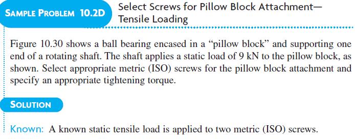
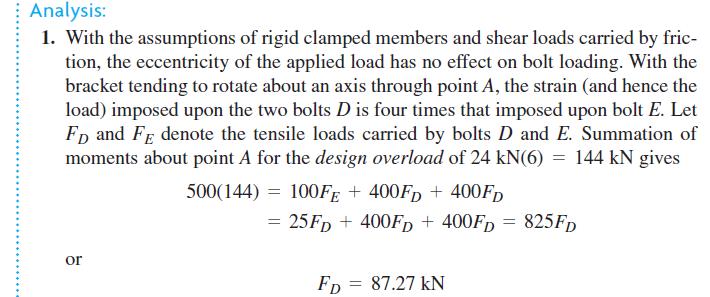
56 The primary loading applied to bolts is tensile, shear, or a combination of the two. Some bending is usually present because the clamped surfaces are not exactly parallel to each other and perpendicular to the bolt axis (Figure 10.29a) and because the loaded members are somewhat deflected (Figure 10.29b). Most times screws and bolts are selected rather arbitrarily. Such is the case with noncritical applications with small loads Almost any size would do, including sizes considerably smaller than the ones used. Selection is a matter of judgment, based on factors such as appearance, ease of handling and assembly, and cost. Even in bolt applications with known significant loads, larger bolts than necessary are used because a smaller size doesn t look right, and the cost penalty of using the larger bolts is minimal.
57
58
59
60
61
62
63
64
65
66
67
68
69
70
71
72
73
74
1/2/2016. Lecture Slides. Screws, Fasteners, and the Design of Nonpermanent Joints. Reasons for Non-permanent Fasteners
 Lecture Slides Screws, Fasteners, and the Design of Nonpermanent Joints Reasons for Non-permanent Fasteners Field assembly Disassembly Maintenance Adjustment 1 Introduction There are two distinct uses
CH # 8. Two rectangular metal pieces, the aim is to join them
 CH # 8 Screws, Fasteners, and the Design of Non-permanent Joints Department of Mechanical Engineering King Saud University Two rectangular metal pieces, the aim is to join them How this can be done? Function
Power Threads. Shigley s Mechanical Engineering Design
 Power Threads Power screw Mechanics of Power Screws Used to change angular motion into linear motion Usually transmits power Examples include vises, presses, jacks, lead screw on lathe Fig. 8 4 Square
Mechanical joints. Major diameter Mean diameter Minor diameter Pitch p chamfer. Root Crest. Thread angle 2a. Dr. Salah Gasim Ahmed YIC 1
 Screw fasteners Helical threads screws are an extremely important mechanical invention. It is the basis of power screws (which change angular motion to linear motion) and threaded fasteners such as bolts,
THE GATE COACHAll Rights Reserved 28, Jia Sarai N.Delhi ,-9998
 1 P a g e 1 DESIGN AGAINST STATIC AND FLUCTUATING LOADS 2 SHAFT, KEYS AND COUPLINGS CONTENTS Introduction 6 Factor of safety 6 Stress concentration 7 Stress concentration factors 8 Reduction of stress
Fasteners. Fastener. Chapter 18
 Fasteners Chapter 18 Material taken from Mott, 2003, Machine Elements in Mechanical Design Fastener A fastener is any device used to connect or join two or more components. The most common are threaded
UNIT 9b: SCREW FASTENERS Introduction Functions Screw Features Elements Terms of a Thread Profile
 UNIT 9b: SCREW FASTENERS Introduction A mechanical screw is a cylinder or cone that has a helical ridge called a thread. A helix has one or more turns, so a screw can have several turns. If the helix is
Threaded Fasteners 2. Shigley s Mechanical Engineering Design
 Threaded Fasteners 2 Bolted Joint Stiffnesses During bolt preload bolt is stretched members in grip are compressed When external load P is applied Bolt stretches further Members in grip uncompress some
AN, MS, NAS Bolts. AN3 20 bolts are identified by a multi-part code:
 AN, MS, NAS Bolts Most bolts used in aircraft structures are either (a) general-purpose, (b) internal-wrenching or (c) close-tolerance AN, NAS, or MS bolts. Design specifications are available in MIL-HDBK-5,
1. Enumerate the most commonly used engineering materials and state some important properties and their engineering applications.
 Code No: R05310305 Set No. 1 III B.Tech I Semester Regular Examinations, November 2008 DESIGN OF MACHINE MEMBERS-I ( Common to Mechanical Engineering and Production Engineering) Time: 3 hours Max Marks:
Hours / 100 Marks Seat No.
 17610 15116 4 Hours / 100 Seat No. Instructions (1) All Questions are Compulsory. (2) Answer each next main Question on a new page. (3) Illustrate your answers with neat sketches wherever necessary. (4)
REVIEW OF THREADED FASTENERS LOOSENING AND ITS EFFECTS
 REVIEW OF THREADED FASTENERS LOOSENING AND ITS EFFECTS Mr. Kale Amol Scholar, M.E. Mechanical Design, V. V. P. Institute of Engineering and Technology, Solapur, India Prof. S. M. Shaikh A.P. Mechanical
MECHANICAL ASSEMBLY John Wiley & Sons, Inc. M. P. Groover, Fundamentals of Modern Manufacturing 2/e
 MECHANICAL ASSEMBLY Threaded Fasteners Rivets and Eyelets Assembly Methods Based on Interference Fits Other Mechanical Fastening Methods Molding Inserts and Integral Fasteners Design for Assembly Mechanical
Bolts and Set Screws Are they interchangeable?
 1903191HA Bolts and Set Screws Are they interchangeable? Prof. Saman Fernando Centre for Sustainable Infrastructure SUT Introduction: This technical note discusses the definitions, standards and variations
A training course delivered at a company s facility by Matrix Engineering, an approved provider of Bolt Science Training
 A training course delivered at a company s facility by Matrix Engineering, an approved provider of Bolt Science Training Following is an outline of the material covered in the training course. Each person
FASTENERS. Aylin YENİLMEZ GÜRKÖK
 FASTENERS Aylin YENİLMEZ GÜRKÖK FASTENERS A fastener is a hardware device that mechanically joins or affixes two or more objects together. Welding, Soldering, Nuts & Bolts, Washers, Screws, Clips, Clamps,
A training course delivered at a company s facility by Matrix Engineering, an approved provider of Bolt Science Training
 A training course delivered at a company s facility by Matrix Engineering, an approved provider of Bolt Science Training Following is an outline of the material covered in the training course. Each person
AN, MS, NAS Bolts. AN3 20 bolts are identified by a multi-part code:
 AN, MS, NAS Bolts Most bolts used in aircraft structures are either (a) general-purpose, (b) internal-wrenching or (c) close-tolerance AN, NAS, or MS bolts. Design specifications are available in MIL-HDBK-5,
UNIVERSITY OF THESSALY
 UNIVERSITY OF THESSALY MECHANICAL ENGINEERING DEPARTMENT Instructor: Dr. S.D. Chouliara e-mail: schoul@uth.gr MACHINE ELEMENTS Task 2 1. Let the bolt in the following Figure be made from cold-drawn steel.
The Engineer s Guide to Identifying Lead Screw Thread Forms
 The Engineer s Guide to Identifying Lead Screw Thread Forms Thread Forms There are hundreds of different thread forms that have been designed over several decades. There are only a few specific thread
Chapter 10 Threaded Fasteners and Power Screws
 Chapter 10 Threaded Fasteners and Power Screws 10.1 Introduction A layan ight consider threaded fasteners (screws, nuts, and bolts) to be the ost undane and uninteresting of all achine eleents. In fact
THREAD CUTTING & FORMING
 THREAD CUTTING & FORMING Threading, Thread Cutting and Thread Rolling: Machining Threads on External Diameters (shafts) Tapping: Machining Threads on Internal Diameters (holes) Size: Watch to 10 shafts
Bolted Joint Design. Mechanical Properties of Steel Fasteners in Service
 Bolted Joint Design There is no one fastener material that is right for every environment. Selecting the right fastener material from the vast array of those available can be a daunting task. Careful consideration
TECH SHEET PEM - REF / THREAD GALLING. SUBJECT: Root causes and guidelines to promote optimized fastener performance TECH SHEET
 PEM - REF / THREAD GALLING SUBJECT: Root causes and guidelines to promote optimized fastener performance Introduction Occasionally, users of our self-clinching fasteners encounter thread binding issues
c. Pins, bolts, and retaining rings b. Washers, locking nuts, and rivets
 62 20 HW 8: Fasteners / Force, Pressure, Density Mechanical Systems DUE Mon, 11/21/16 Start of class Check link on website for helpful fastener information Please use a scantron. Material is based primarily
ERECTION & CONSTRUCTION
 ERECTION & CONSTRUCTION High Strength Structural Bolting Author: Clark Hyland Affiliation: Steel Construction New Zealand Inc. Date: 24 th August 2007 Ref.: Key Words High Strength Bolts; Property Class
Bolt Tensioning. This document is a summary of...
 If you want to learn more about best practice machinery maintenance, or world class mechanical equipment maintenance and installation practices, follow the link to our Online Store and see the Training
METRIC FASTENERS 1520 METRIC FASTENERS
 1520 METRIC FASTENERS METRIC FASTENERS A number of American National Standards covering metric bolts, screws, nuts, and washers have been established in cooperation with the Department of Defense in such
Fasteners Table of Contents
 EML2322L Design & Manufacturing Laboratory Fasteners Table of Contents I. Copyright Notice II. Why Care? 1. Definitions 2. Common Fastener Types 3. Fastener Nomenclature 4. Fastener Thread Types 5. Rolled
STUDY AND ANALYSIS OF ANGULAR TORQUING OF ENGINE CYLINDER-HEAD BOLTS USING TORQUE-TO-YIELD BOLTS: A CASE STUDY
 International Journal of Mechanical and Production Engineering Research and Development (IJMPERD) ISSN 2249-6890 Vol. 3, Issue 4, Oct 2013, 1-10 TJPRC Pvt. Ltd. STUDY AND ANALYSIS OF ANGULAR TORQUING OF
DUO-TAPTITE. Fasteners DUO-TAPTITE. Thread Rolling Screws
 Fasteners Percent thread chart... Page 8 Pilot hole sizes... Page 9 Typical torque performance... Page 10 Typical single punch extruded holes... Pages 11 & 12 Die cast cored holes... Page 12 CORFLEX...
DESIGN OF MACHINE MEMBERS-I
 Code No: R31035 R10 Set No: 1 JNT University Kakinada III B.Tech. I Semester Regular/Supplementary Examinations, Dec - 2014/Jan -2015 DESIGN OF MACHINE MEMBERS-I (Mechanical Engineering) Time: 3 Hours
In normal joints, the clamping force should equal the working load. In gasketed joints, it should be sufficient to create a seal.
 Fastener Quality Act Information Unbrako offers this link to the National Institute of Standards homepage on the Fastener Quality Act as an aide to individuals who need detailed and complete information
Welded connections Welded connections are basically the same design in AISI as in AISC. Minor differences are present and outlined below.
 Cold-Formed Steel Design for the Student E. CONNECTIONS AND JOINTS E1 General Provisions Connections shall be designed to transmit the maximum design forces acting on the connected members. Proper regard
A training course delivered to Engineers and Designers, at a company s premises, on the technical aspects of bolting.
 A training course delivered to Engineers and Designers, at a company s premises, on the technical aspects of bolting. Consulting Analysis Services Software Training An outline is presented below of the
Permanent fasteners: Riveted joints Welded joints Detachable joints: Threaded fasteners screws, bolts and nuts, studs. Cotter joints Knuckle joints
 Instructional Objectives At the end of this lesson, the students should have the knowledge of Fasteners and their types: permanent and detachable fasteners. Different types of pin joints. Different types
Mechanical Drawing (MDP 115)
") Mechanical Drawing (MDP 115) FirstYear, Mechanical Engineering Dept., Faculty of Engineering, Fayoum University Dr. Ahmed Salah Abou Taleb Threads and Fasteners Topics Exercises 2 Threads & Fasteners:
Mechanical Drawing (MDP 115) FirstYear, Mechanical Engineering Dept., Faculty of Engineering, Fayoum University Dr. Ahmed Salah Abou Taleb Threads and Fasteners Topics Exercises 2 Threads & Fasteners:
Evaluation of In-Pavement Light Fixture Designs and Performance
 Evaluation of In-Pavement Light Fixture Designs and Performance Presented to: IES ALC Fall Technology Meeting By: Joseph Breen Date: Background In-Pavement Light Fixture Assemblies Utilize a Circle of
Fluid Sealing Association
 Fluid Sealing Association STANDARD FSA-MG-501-02 STANDARD TEST METHOD FOR INWARD BUCKLING OF SPIRAL-WOUND GASKETS 994 Old Eagle School Road, Suite 1019 Wayne, Pennsylvania 19087-1866 Phone: (610) 971-4850
UNDERSTANDING TORQUE -ANGLE SIGNATURES OF BOLTED JOINTS
 SENSORS FOR RESEARCH & DEVELOPMENT WHITE PAPER #23 UNDERSTANDING TORQUE -ANGLE SIGNATURES OF BOLTED JOINTS THREADED FASTENER TORQUE-ANGLE CURVE ANALYSIS Written By Jeff Drumheller www.pcb.com info@pcb.com
TECH SHEET PEM - REF / TESTING CLINCH PERFORMANCE. SUBJECT: Testing clinch performance of self-clinching fasteners.
 PEM - REF / TESTING CLINCH PERFORMANCE SUBJECT: Testing clinch performance of self-clinching fasteners. A self-clinching fastener s performance can be divided into two major types. The first is self-clinching
What is a fastener? A device to locate or hold parts
 What is a fastener? A device to locate or hold parts As a repair technician you will become skilled at removing, reconditioning, replacing, and installing fasteners. An important skill to learn is how
Machining. Module 6: Lathe Setup and Operations. (Part 2) Curriculum Development Unit PREPARED BY. August 2013
 Curriculum Development Unit PREPARED BY. August 2013") Machining Module 6: Lathe Setup and Operations (Part 2) PREPARED BY Curriculum Development Unit August 2013 Applied Technology High Schools, 2013 Module 6: Lathe Setup and Operations (Part 2) Module Objectives
Machining Module 6: Lathe Setup and Operations (Part 2) PREPARED BY Curriculum Development Unit August 2013 Applied Technology High Schools, 2013 Module 6: Lathe Setup and Operations (Part 2) Module Objectives
Fastener Handout. Introduction: Engineering Design Representation 2. Threads 2. Local Notes (callouts) 8. Threaded Mechanical Fasteners 13
 8. Threaded Mechanical Fasteners 13") Fastener Handout Introduction: Engineering Design Representation 2 Threads 2 Effect of thread angle on strength: 3 Standardization of Threads: 4 Descriptions of the Thread Series: 4 Class fit: 5 Specification
Fastener Handout Introduction: Engineering Design Representation 2 Threads 2 Effect of thread angle on strength: 3 Standardization of Threads: 4 Descriptions of the Thread Series: 4 Class fit: 5 Specification
TECH SHEET PEM - REF / AXIAL THREAD CLEARANCE. SUBJECT: Method for providing adequate axial thread clearance
 SUBJECT: Method for providing adequate axial thread clearance In our long history of working with customers in the application of our self-clinching nuts, PennEngineering has seen numerous instances of
LOCTITE WEBINAR SERIES Threadlocking & the Torque-Tension Relationship
 LOCTITE WEBINAR SERIES Threadlocking & the Torque-Tension Relationship Meet Your Presenters Doug Lescarbeau Michael Feeney Market Development Director Doug.Lescarbeau@Henkel.co m Application Engineer Michael.Feeney@Henkel.com
Fasteners. Bolts. NAPA FastTrack Counter Sales Training Fasteners Page 1. Figure 1. Typical Measurements for a Bolt or Hex Head Cap Screw
 Fasteners Many types and sizes of fasteners are used in the automotive industry. Each fastener is designed for a specific purpose and condition. One of the most commonly used type of fastener is the threaded
SCREW THREADS. = minor diameter. d 3. d 2. = pitch diameter
 ISO : 6 Part 2 DIN : Part /20 Metric (ISO) screw thread, coarse series -M- T-00 T-002 for M to incl. M,4, fit H/6h The bold lines indicate the maximum material profiles. The maximum material profile of
Screws. Introduction. 1. Nuts, bolts and screws used to clamp things together. Screws are used for two purposes:
 Screws Introduction Screws are used for two purposes: 1. To clamp things together. 2. To control motion. 1. Nuts, bolts and screws used to clamp things together. Nuts, bolts and screws that are used for
Air Cooled Engine Technology. Roth 9 th Ch 3 Fasteners & Sealing Pages 45 65
 Roth 9 th Ch 3 Fasteners & Sealing Pages 45 65 1. Engine & equipment can be common or can be designed to perform specific functions. Fasteners Options Features 2. The of a fastener is actually an inclined
ISO INTERNATIONAL STANDARD. Fasteners Torque/clamp force testing. Éléments de fixation Essais couple/tension. First edition
 Provläsningsexemplar / Preview INTERNATIONAL STANDARD ISO 16047 First edition 2005-02-01 Fasteners Torque/clamp force testing Éléments de fixation Essais couple/tension Reference number ISO 16047:2005(E)
Interference Fits Interference Fits Reference Lecture 15 Notes
 Interference Fits Interference Fits Hole is undersized and part is heated to allow it to slide over shaft. Compressive interface pressure develops when part cools. Reference Lecture 15 Notes. Keys and
Connection and Tension Member Design
 Connection and Tension Member Design Notation: A = area (net = with holes, bearing = in contact, etc...) Ae = effective net area found from the product of the net area An by the shear lag factor U Ab =
FASTENERS, MEASUREMENTS AND CONVERSIONS
 FASTENERS, MEASUREMENTS AND CONVERSIONS Bolts, Nuts and Other Threaded Retainers Although there are a great variety of fasteners found in the modern car or truck, the most commonly used retainer is the
Dowel-type fasteners. Timber Connections. Academic resources. Introduction. Deferent types of dowel-type fasteners. Version 1
 Academic resources Timber Connections Dowel-type fasteners Version 1 This unit covers the following topics: Deferent types of dowel-type fasteners Introduction There are four criteria designers should
3-D Finite Element Analysis of Bolted Joint Using Helical Thread Model
 3-D Finite Element Analysis of Bolted Joint Using Helical Thread Model Shaik Gousia Yasmin 1, P. Punna Rao 2, Kondaiah Bommisetty 3 1 M.Tech(CAD/CAM), Nimra College of Engineering & Technology, Vijayawada,
TAPTITE 2000 Fasteners
 TAPTITE 2000 Fasteners Unique Design Increases Performance TAPTITE 2000 fasteners are designed to provide the benefits of previous TAPTITE fastener products with an innovative new thread design the Radius
SECTION 3. BOLTS. bolt is a standard AN-type or a special-purpose bolt, and sometimes include the manufacturer.
 9/8/98 AC 43.13-1B SECTION 3. BOLTS 7-34. GENERAL. Hardware is the term used to describe the various types of fasteners and small items used to assemble and repair aircraft structures and components. Only
Sockets. Dimensions; Mechanical & Performance Requirements. Socket Head Cap Screws Body & Grip Lengths - Socket Cap Screws...
 imensions; Mechanical & Performance Requirements Socket Head Cap Screws... 2-4 Body & Grip Lengths - Socket Cap Screws... 5-6 Low Head Socket Cap Screws... 7 Button Head Socket Cap Screws... 8 Flat Head
BOLTCALC Program. problems. User Guide. Software for the Analysis of Bolted Joints
 User Guide BOLTCALC Program Software for the Analysis of Bolted Joints problems BOLTCALC is produced by Bolt Science Limited Bolt Science provides analytical solutions to bolting problems www.boltscience.com
TAPTITE 2000 HEAT TREATMENT. Increased out of round of point threads. Low thread forming torque
 TAPTITE 2000 thread forming technology joins two unique concepts and advances fastener performance to new levels. TAPTITE 2000 fasteners afford end-users with enhanced opportunities to reduce the overall
SPIETH Locknuts. Series MSW. Works Standard SN 04.03
 SPIETH Locknuts Series MSW Works Standard SN 0.03 SPIETH Locknuts Series MSW SPIETH locknuts offer a range of technical benefits, qualified by their special system and production. Under high levels of
Failure of Engineering Materials & Structures. Code 34. Bolted Joint s Relaxation Behavior: A FEA Study. Muhammad Abid and Saad Hussain
 Failure of Engineering Materials & Structures Code 3 UET TAXILA MECHNICAL ENGINEERING DEPARTMENT Bolted Joint s Relaxation Behavior: A FEA Study Muhammad Abid and Saad Hussain Faculty of Mechanical Engineering,
Tex-452-A, Rotational Capacity Testing of Fasteners Using a Tension Measuring Device
 Using a Tension Measuring Device Contents: Section 1 Overview...2 Section 2 Definitions...3 Section 3 Apparatus...4 Section 4 Part I, Rotational Capacity Testing...5 Section 5 Part II, Values for Fasteners
Factors Affecting Pre-Tension and Load Carrying Capacity in Rockbolts - A Review of Fastener Design
 University of Wollongong Research Online Coal Operators' Conference Faculty of Engineering and Information Sciences 2018 Factors Affecting Pre-Tension and Load Carrying Capacity in Rockbolts - A Review
TORQUE DESIGN, ANALYSIS AND CHARACTERIZATION OF CRITICAL FASTENERS IN DIESEL ENGINES
 TORQUE DESIGN, ANALYSIS AND CHARACTERIZATION OF CRITICAL FASTENERS IN DIESEL ENGINES ROHIT PATIL 1, MUKUND NALAWADE 2, NITIN GOKHALE 3. 1 P.G. Student, Department of Mechanical Engineering, Vishwakarma
TAPTITE Fasteners. High Performance Thread Rolling Screws for Metals
 TAPTITE 2000 Fasteners High Performance Thread Rolling Screws for Metals TAPTITE 2000 thread forming technology joins two unique concepts and advances fastener performance to new levels. TAPTITE 2000 fasteners
Formulae for calculations A) Nomenclature
 Nomenclature") Formulae for calculations A) Nomenclature do= Nominal diameter {Outside diameter of screw} dc= Core diameter of screw d= Mean Diameter of the screw p= Pitch of the screw. ) Thread angle ( α) α = tan 1
Formulae for calculations A) Nomenclature do= Nominal diameter {Outside diameter of screw} dc= Core diameter of screw d= Mean Diameter of the screw p= Pitch of the screw. ) Thread angle ( α) α = tan 1
Practical Bolting and Gasketing for the Non Standard-Flanged Joint
 Practical Bolting and Gasketing for the Non Standard-Flanged Joint Points of Discussion Introduction Joint Analysis Existing Flange Data Machining Procedure Bolting Radial Shear Available Gasket Styles
Clearview Railing System Installation Instructions
 Clearview Railing System Installation Instructions Disclaimer: AGS Stainless, Inc. has its Clearview Railing Systems designed by a professional engineer to meet the requirements of the latest national
Installing the Partridge RA Extension on Losmandy G11
 Installing the Partridge RA Extension on Losmandy G11 Michael Herman July 20, 2015 Tools: 3/16 inch hex key (allen wrench) [If desired for DEC indicator ring friction improvement: flat screwdriver, and
MATERIAL COMBINATION NUMBER 2: Corrosive environment requiring harder, wear-resistant seating faces and resistance to dezincification.
 Cast Iron Slide Gates Spec Sheet General The contractor shall furnish and install the following cast iron slide gate assemblies as listed on the Gate Schedule and detailed on the manufacturer s drawings.
Structural Bolting. Notice the Grade 5 has a much smaller head configuration and a shorter shank then the grade A325 structural bolt.
 Structural Bolting ASTM F3125/F3125M is a structural bolt specification covering inch and metric bolt grades. This specification contains 4 inch series bolting grades: A325, F1852, A490, and F2280. These
Student, Department of Mechanical Engineering, Knowledge Institute of Technology, Salem, Tamilnadu (1,3)
") International Journal of Scientific & Engineering Research, Volume 7, Issue 5, May-2016 11 Combined Drilling and Tapping Machine by using Cone Mechanism N.VENKATESH 1, G.THULASIMANI 2, S.NAVEENKUMAR 3,
International Journal of Scientific & Engineering Research, Volume 7, Issue 5, May-2016 11 Combined Drilling and Tapping Machine by using Cone Mechanism N.VENKATESH 1, G.THULASIMANI 2, S.NAVEENKUMAR 3,
C-Clamps and Lifting Eyes (Eye Bolts)
") 0-C-Clamps & Lifting Eyes-R 2/21/08 9:42 PM Page 1 C-Clamps A B C Armstrong C-Clamps When your requirements call for clamps, specify Armstrong the most accepted name in the business. When you see Armstrong
0-C-Clamps & Lifting Eyes-R 2/21/08 9:42 PM Page 1 C-Clamps A B C Armstrong C-Clamps When your requirements call for clamps, specify Armstrong the most accepted name in the business. When you see Armstrong
Note: Conditions where bending loads are imposed on the bolt e.g. non-parallel bolting surfaces, should be avoided.
 Bolted Joint Design Introduction A most important factor is machine design, and structural design is the rigid fastening together of different components. This should include the following considerations..
Module 3 Selection of Manufacturing Processes
 Module 3 Selection of Manufacturing Processes Lecture 4 Design for Sheet Metal Forming Processes Instructional objectives By the end of this lecture, the student will learn the principles of several sheet
Load application in load cells - Tips for users
 Load application in load cells - Tips for users Correct load application on the load cells is a prerequisite for precise weighing results. Be it load direction, support structure or mounting aids load
5-axis clamping system compact
 5-axis clamping system compact 395 5-axis clamping system compact Function We are setting standards with the new KIPP 5-axis clamping system compact in this field. The system was specifically designed
Disclaimer. Socket Products Socket depth limits maximum torque. Torque figures are based on 80% of maximum torque for a given key size.
 E546 V3 (1/17) Disclaimer Torque values listed in this book are based on mathematical calculations and experimental data. The values are valid only when the matched strength system listed is used. The
Installation and Operational Instructions for ROBA -DS couplings Type 95. _ (disk pack HF) Sizes
 Sizes") 95. _ (disk pack HF) Sizes 6 22 Please read these Operational Instructions carefully and follow them accordingly! Ignoring these Instructions may lead to malfunctions or to coupling failure, resulting
95. _ (disk pack HF) Sizes 6 22 Please read these Operational Instructions carefully and follow them accordingly! Ignoring these Instructions may lead to malfunctions or to coupling failure, resulting
ROOP LAL Unit-6 Lathe (Turning) Mechanical Engineering Department
 Mechanical Engineering Department") Notes: Lathe (Turning) Basic Mechanical Engineering (Part B) 1 Introduction: In previous Lecture 2, we have seen that with the help of forging and casting processes, we can manufacture machine parts of
Notes: Lathe (Turning) Basic Mechanical Engineering (Part B) 1 Introduction: In previous Lecture 2, we have seen that with the help of forging and casting processes, we can manufacture machine parts of
Fastener Basics. Common Fastener Types. Fastener Materials. Grade / Class and Fastener Strength
 Fastener Basics Common Fastener Types Fastener Grade (US) or Class (metric) refers to the mechanical properties of the fastener material. Generally, a higher number indicates a stronger, more hardened
Question Bank Technical Drawing Metal
 Question Bank Technical Drawing Metal Table of Contents Question Bank Technical Drawing Metal...1 ASSEMBLY DRAWINGS & DETAILS...1 READING OF DRAWINGS...38 VIEWS...61 MACHINE ELEMENTS...87 i ii Question
MTS-SP100. RENOGY Pole Mount System E Philadelphia St, Ontario, CA Version: 1.2
 MTS-SP100 RENOGY Pole Mount System 2775 E Philadelphia St, Ontario, CA 91761 1-800-330-8678 1 Version: 1.2 Important Safety Instructions Please save these instructions. This manual contains important safety,
of Screwed Joints. Screwed Joints n 377
 Screwed Joints n 377 C H A P T E R 11 Screwed Joints 1. Introduction.. Advantages and Disadvantages of Screwed Joints. 3. Important Terms used in Screw Threads. 4. Forms of Screw Threads. 5. Location of
Chapter 7. Fasteners
 Chapter 7 Fasteners LEARNING OBJECTIVES After studying this chapter, students will be able to: Identify several types of fasteners. Explain why inch-based fasteners are not interchangeable with metric-based
4) Drive Mechanisms. Techno_Isel H830 Catalog
 Drive Mechanisms. Techno_Isel H830 Catalog") 4) Drive Mechanisms This section will introduce most of the more common types of drive mechanisms found in linear motion machinery. Ideally, a drive system should not support any loads, with all the loads
4) Drive Mechanisms This section will introduce most of the more common types of drive mechanisms found in linear motion machinery. Ideally, a drive system should not support any loads, with all the loads
Metals can be bought from suppliers in standardized forms and sizes, such as round,
 1.4 METAL CUTTING BAND SAWS: Metals can be bought from suppliers in standardized forms and sizes, such as round, rectangular or square bar stock or in the form of large sheets (plates). Bar stock normally
Mechanical Drawing. Fig 5-1
 College of Engineering 1 Mechanical Drawing Mechanical Engineering Department Mechanical Drawing Lecture 5 Keys and keyways 5-1 Introduction A key, Fig. 5.1, is usually made from steel and is inserted
Thread Repair & Thread Protection
 Thread Repair & Thread Protection Screw Thread Inserts, Kits & Components for Industrial Maintenance, Repair and Overhaul Bulletin 998 C E R T I F I E D ISO 9001 AS 9100 TS 16949 ISO 14001 The HELI-COIL
Hydraulic Tensioner Assembly: Load Loss Factors and Target Stress Limits
 Proceedings of the ASME 214 Pressure Vessels & Piping Conference PVP214 July 2-24, 214, Anaheim, California, USA PVP214-28685 Hydraulic Tensioner Assembly: Load Loss Factors and Target Stress Limits Warren
SPECIFICATION FOR HIGH STRENGTH STRUCTURAL BOLTS
 UDC 621.882.211 [669.14.018.291] IS : 3757-1985 (Reaffirmed 2003) Edition 3.2 (1989-07) Indian Standard SPECIFICATION FOR HIGH STRENGTH STRUCTURAL BOLTS ( Second Revision ) (Incorporating Amendment Nos.
Replacement of Pitch Link Retainer and Service Improvement of the Pitch Control System. Effectivity: Helicopters manufactured prior to January, 1981
 Page 1 of 12 Date: December 2, 1981 Subject: Models: Replacement of Pitch Link Retainer and Service Improvement of the Pitch Control System F-28C and 280C Effectivity: Helicopters manufactured prior to
HEICO FASTENING SYSTEMS. Simple Fast Reliable HEICO-TEC TENSION NUT
 HEICO FASTENING SYSTEMS Simple Fast Reliable HEICO-TEC TENSION NUT WWW.HEICO-TEC.COM HEICO-TEC TENSION NUT SIMPLE FAST RELIABLE For a secure joint with a HEICO-TEC tension nut, no electric, hydraulic,
DEVELOPMENT OF A NOVEL TOOL FOR SHEET METAL SPINNING OPERATION
 DEVELOPMENT OF A NOVEL TOOL FOR SHEET METAL SPINNING OPERATION Amit Patidar 1, B.A. Modi 2 Mechanical Engineering Department, Institute of Technology, Nirma University, Ahmedabad, India Abstract-- The
Fasteners. Metal Fasteners, Joining, and Adhesives. Bolts. Metal Fasteners, Joining, and Adhesives
 Metal Fasteners, Joining, and Adhesives Fasteners Metal assemblies are often held together with fasteners, hardware devices that mechanically join or affix two or more objects together. Assembling with
An Investigation of Optimal Pitch Selection to Reduce Self-Loosening of Threaded Fastener under Transverse Loading
 IJSTE - International Journal of Science Technology & Engineering Volume 3 Issue 01 July 2016 ISSN (online): 2349-784X An Investigation of Optimal Pitch Selection to Reduce Self-Loosening of Threaded Fastener
Components made of special materials. Floor Elements for Profile St Profile KH. Fastening Elements for Profile KH
 Profile Fastening Elements for Profile Floor Elements for Profile Profile KH Fastening Elements for Profile KH Components made of special materials Products in this section Profile 8 x eel profile that
SECTION 7. SAFETYING
 9/8/98 AC 43.13-1B SECTION 7. SAFETYING 7-122. GENERAL. The word safetying is a term universally used in the aircraft industry. Briefly, safetying is defined as: Securing by various means any nut, bolt,