20-SDMS-02 REV. 02 SPECIFICATIONS FOR OVERHEAD LINE ACCESSORIES
|
|
|
- Aileen Summers
- 5 years ago
- Views:
Transcription
1 20-SDMS-02 REV. 02 SPECIFICATIONS FOR OVERHEAD LINE ACCESSORIES This specification is property of SEC and subject to change or modification without any notice
2 TABLE OF CONTENTS PAGE 1.0 SCOPE CROSS REFERENCES APPLICABLE CODES AND STANDARDS SERVICE CONDITIONS AND SYSTEM PARAMETERS DESIGN AND CONSTRUCTION REQUIREMENTS General 8 Table 1 List of Overhead Line Accessories Fabricated Steel Shapes and Plates Bolts, Nuts, Washers and Anchor Rods 14 Table 2 Summary of Bolt sizes Stay Wire and Preformed Guy Grip Insulator and Conductor Hardware Fittings Connectors Anti-Climbing Device Grounding Rods and Earth Electrodes Danger, Numbering and Phasing Plates Non-Metal Accessories INSPECTION AND TESTING PACKING AND SHIPPING GUARANTEE SUBMITTALS TECHNICAL DATA SCHEDULES OVERHEAD LINE ACCESSORIES DRAWINGS 38 Page 2 of 105
3 1.0 SCOPE This SEC Material Standard Specification (SDMS) specifies the minimum technical requirement for design, engineering, manufacturing, inspection, testing and performance of accessories for overhead lines to be used in the medium and low voltage system (MV/LV) of Saudi Electricity Company (SEC). 2.0 CROSS REFERENCES 2.1 The Material Standard Specification shall be read in conjunction with SEC General Specification No. 01-SDMS-01 (latest revision) for General Requirement for all Equipment/Materials as an integral part of this SDMS. 2.2 This SDMS shall also be read in conjunction with SEC purchase order requirements. 3.0 APPLICABLE CODES AND STANDARDS The latest revision of the following codes and standards shall be applicable for the equipment/materials covered in this SDMS. In case of any deviation, the vendor/manufacturer may propose equipment/materials conforming to alternate codes or standards. However, the provisions of SEC Standards shall supersede the provisions of these alternate standards in case of any difference. 3.1 ASTM A6 Specification for General Requirements for Rolled Steel Plates, Shapes, Sheet Piling and Bars for Structural Use 3.2 ASTM A36M Standard Specification for Carbon Structural Steel 3.3 ASTM A121 Standard Specification for Zinc Coating (Galvanized) Steel Barbed Wire 3.4 ASTM A123 Standard Specification for Zinc (Hot-Dip Galvanized) Coatings of Iron and Steel Products 3.5 ASTM A143 Standard Practice for Safeguarding Against Embrittlement of Hot-Dip Galvanized Structural Steel Products and Procedure for Detecting Embrittlement 3.6 ASTM A153 Standard Specification for Zinc Coating (Hot-Dip) on Iron and Steel Hardware Page 3 of 105
4 3.7 ASTM A239 Standard Test Method for Locating the Thinnest Spot in a Zinc (Galvanized) Coating on Iron or Steel Articles by the Preece Test (Copper Sulfate Dip) 3.8 ASTM A307 Standard Specification for Carbon Steel Bolts and Studs, PSI Tensile Strength 3.9 ASTM A325 Standard Specification for Structural Bolts, Steel, Heat- Treated, 120/105 PSI Minimum Tensile Strength 3.10 ASTM A325M Standard Specification for High Strength Bolts for Structural Steel Joints (Metric) 3.11 ASTM A354 Standard Specification for Quenched and Tempered Alloy Steel Bolts, Studs and Other Externally Threaded Fasteners 3.12 ASTM A370 Standard Test Methods and Definitions for Mechanical Testing of Steel Products 3.13 ASTM A384 Standard Practice for Safeguarding Against Warpage and Distortion During Hot-Dip Galvanizing of Steel Assemblies 3.14 ASTM A385 Standard Practice for Providing High Quality Zinc Coatings (Hot-Dip) 3.15 ASTM A475 Standard Specification for Zinc-Coated Steel Wire Strand 3.16 ASTM A510 Standard Specification for General requirements for Wire Rods and Coarse Round Wire, Carbon Steel 3.17 ASTM A563M Standard Specification for Carbon and Alloy Steel Nuts (Metric) 3.18 ASTM A687 Standard Specification for High-Strength Non-Headed Steel Bolts and Studs 3.19 ASTM B6 Specification for Zinc (Slab Zinc) 3.20 ASTM B98 Standard Specification for Copper-Silicon Alloy Rod, Bar and Shapes Page 4 of 105
5 3.21 ASTM B139 Standard Specification for Phosphor Bronze Rod, Bar and Shapes 3.22 ASTM B140 Standard Specification for Copper-Zinc-Lead (Red Brass or Hardware Bronze) Rod, Bar and Shapes 3.23 ASTM B150 Standard Specification for Aluminum Bronze Rod, Bar and Shapes 3.24 ASTM B249 Standard Specification for General Requirements for Wrought Copper and Copper-Alloy Rod, Bar and Shapes 3.25 ASTM B580 Specification for Anodic Oxide Coatings on Aluminum 3.26 ASTM E165 Standard Test Method for Liquid Penetrant Examination 3.27 ASTM E376 Standard Practice for Measuring Coating Thickness by Magnetic-Field or Eddy-Current (Electromagnetic) Testing Methods 3.28 ASTM F436M Standard Specification for Hardened Steel Washers 3.29 ASTM F541 Standard Specification for Alloy Steel Eyebolts 3.30 ASTM F568 Specification for Carbon and Alloy Steel Externally Threaded Metric Fasteners 3.31 ASTM F606 Standard Test Materials for Determining the Mechanical Properties of Externally and Internally Threaded Fasteners, Washers and Rivets 3.32 ASTM A53 Standard Specification for Pipe, Steel, Black and Hot- Dipped Zinc-Coated Welded and Seamless 3.33 ANSI B1.13M Metric Screw Threads 3.34 ANSI B Metric Heavy Hex Nuts 3.35 ANSI B Plain Washers 3.36 ANSI C135.1 Galvanized Steel Bolts and Nuts for Overhead Line Construction Page 5 of 105
6 3.37 IEEE C135.2 Threaded Galvanized Ferrous Strand-Eye Anchor Rods and Nuts for Overhead Line Construction 3.38 ANSI C119.4 Electric Connectors Connectors for Use Between Aluminum-to-Aluminum or Aluminum-to-Copper Bare Overhead Conductors 3.39 NEMA CC 3 Standard Connectors for Use Between Aluminum or Aluminum-to-Copper Bare Overhead Conductors 3.40 NEMA GR 1 Grounding Rod Electrodes and Grounding Rod Electrode Couplings 3.41 AISC Manual of Steel Construction, 14th Edition 3.42 AWS D1.1 Structural Welding Code, Steel 3.43 BS 183 General Purpose Galvanized Steel Wire Strand 3.44 BS 464 Thimbles for Wire Ropes 3.45 BS 1470 Wrought Aluminum and Aluminum Alloys for General Engineering Purposes, Plate, Sheet and Strip 3.46 BS 3692 ISO Metric Precision Hexagon Bolts, Screws and Nuts 3.47 BS 3288 Specification for Insulators and Conductor Fittings for Overhead Power Lines 3.48 BS 4102 Steel Wire for Fences 3.49 BS 4360 Specification for Weldable Structural Steels 3.50 ISO 630 Standards for Structural Steels 3.51 ISO R657 Recommendation for Hot-Rolled Steel Sections 3.52 ISO 1459 Metallic Coatings - Protection Against Corrosion by Hot Dip Galvanizing - Guiding Principles Page 6 of 105
7 3.53 ISO 1460 Metallic Coatings - Hot-Dip Galvanized Coatings on Ferrous Materials - Gravimetric Determination of the Mass per Unit Area 3.54 ISO 1461 Metallic Coatings - Hot Dip Galvanized Coatings on Fabricated Ferrous Products - Requirements 3.55 ISO 3575 Continuous Hot-Dip Zinc-Coated Carbon Steel Sheet of Commercial, Lock-Forming and Drawing Qualities 3.56 ISO 4997 Cold-Reduced Steel Sheet of Structural Quality 3.57 ISO 4998 Continuous Hot-Dip Zinc-Coated Carbon Steel Sheet of Structural Quality 3.58 ISO 7413 Hexagon Nuts for Structural Bolting, Style 1, Hot-Dip Galvanized (Oversize Tapped) - Product Grades A and B - Property Classes 5, 6 and ISO 7417 Hexagon Nuts for Structural Bolting - Style 2, Hot-Dip Galvanized (Oversize Tapped) - Product Grade A - Property Class SASO/SSA 39 Mechanical Testing of Welded Joints 3.61 SASO/SSA 107 Tensile Testing of Steel 3.62 SASO/SSA 157 Charpy Method of Impact Test on Metals 3.63 SASO/SSA 199 Methods of Tests for Steel Wire Ropes 3.64 SASO/SSA 200 Steel Wire Ropes for General Purposes 3.65 EN Copper and Copper-Alloys Copper Profiles and Profile Wire for Electrical Purposes 3.66 DIN Copper for Electrical Purposes 3.67 IEC Flexible Non-Metallic Conduit System 3.68 IEC Overhead Lines Requirements and Tests for Fittings Page 7 of 105
8 3.69 IEC Lightning Protection System Components (LPSC) Part 1: Requirements for Connection Components 3.70 IEC Lightning Protection System Components (LPSC) Part 2: Requirements for Conductors and Earth Electrodes 3.71 EN Flexible Non-Metallic Conduit System 4.0 SERVICE CONDITIONS AND SYSTEM PARAMETERS The overhead line accessories shall be suitable for operation under the service conditions and system parameters given in the latest revision of SEC General Specification No. 01- SDMS DESIGN AND CONSTRUCTION REQUIREMENTS 5.1 General All accessories associated with distribution poles for the installations of insulators, conductors, stays, transformer, grounding, etc. are included in this specification. These broadly include but not limited to the materials listed in Table The overhead line accessories shall be of manufacturer s standard design and shall meet or exceed the performance requirements of this Specification in all respects Manufacturer s drawings, as required by 01-SDMS-01, shall show the details of the overhead line accessories, together with all pertinent dimensions. Any variations in these dimensions due to manufacturing tolerances shall be indicated All the materials shall be of the highest grade, free from defects and imperfections, of recent manufacture and unused, and of the classification and grades designated, conforming to the requirements of the latest issue of the appropriate specifications cited herein Workmanship and general finish shall be of the highest grade and the best modern practice. Page 8 of 105
9 Table 1 (Sheet 1 of 4) LIST OF OVERHEAD LINE ACCESSORIES Brief Description Application Fig. No. Page No. Crossarm, L 100x100x12x2400 Mounting of insulators 1 38 Fuse Cutout Mounting Channel Transformer installation 2 39 Fuse Cutout Mounting Channel Transformer installation 2A 40 Transformer Mounting Channel Transformer installation 3 41 Brace, L 50x50x4x828 Crossarm installation Brace, L 50x50x4x828 Crossarm installation. 4A 43 Earthwire Suspension Support Earth conductor installation Earthwire Support Assembly Earth conductor installation 6 45 Double Arming Plate, 100x12x700 Double crossarm installation Horizontal Insulator Mounting Bracket Vertical line configuration 8 47 Spool Insulator Bracket LV quadruplex installation Pole Band (Stay Clamp) For Octagonal Steel Pole Stay wire installation Anti-Climbing Device, Barbed Wire Steel pole installation Buckle Locking Clip, Barbed Wire Steel pole installation. 13A 51 Machine Bolt, M16 Fastener Machine Bolt, M20 Fastener Shoulder Eye Bolt, M16 Suspension insulator and LV conductor attachment Page 9 of 105
10 Table 1 (Sheet 2 of 4) LIST OF OVERHEAD LINE ACCESSORIES Brief Description Shoulder Eye Bolt, M20 Eye Nut For M16 Eye Nut For M20 Application Suspension insulator and LV conductor attachment Suspension insulator and LV conductor attachment Suspension insulator and LV conductor attachment Fig. No. Page No Anchor Shackle Suspension insulator attachment Clevis Eye Extension Suspension insulator attachment Anchor Rods Thimble Eye Stay wire installation Anchor Rods Twin Eye Stay wire installation. 22A 61 Steel Plate For Anchor Rod Stay wire installation Preformed Guy Grip Stay wire installation Guy Thimble Stay wire installation Guy Wire Guard, Yellow Color, 2.44m Stay wire installation Strain Clamp, 3 U-Bolts Type Conductor fitting Strain Clamp, Straight Line Deadend Conductor fitting Suspension Clamp Conductor fitting Full Tension Compression Sleeve Conductor fitting Repair Sleeve Overhead bare conductor repair Insulated Type Sleeve For Connecting Quadruplex Cables LV Quadruplex connection Page 10 of 105
11 Table 1 (Sheet 3 of 4) LIST OF OVERHEAD LINE ACCESSORIES Brief Description Application Fig. No. Page No. Preformed Line Post Insulator Top Tie Fixing of MV conductor Preformed Line Post Insulator Side Tie Fixing of MV conductor Spool Insulator Side Tie Fixing of LV conductor Preformed Armor Rod Conductor protection Parallel Groove Compression Connector Jumper / Line Tap connection Parallel Groove Connector Bolted Jumper / Line Tap connection 39A 77 LV Connector Cover Sealing of LV connector Terminal Plug Connection to cutout Grounding Rod 16mm Dia. Grounding installation Ground Rod Clamp U-Bolt type Grounding installation Crimpit Copper Connector Grounding installation mm² Flexible Copper Cored Wire with Tin Plated Copper Lugs Grounding installation PVC Ground Wire Guard Grounding installation Danger Sign Plate for MV Equipment Danger Sign Plate for LV Equipment Danger warning sign for medium-voltage installation Danger warning sign for lowvoltage installation A 86 Danger Sign Mounting Bracket Danger plate installation Pole Numbering Plates Pole numbering installation Page 11 of 105
12 Table 1 (Sheet 4 of 4) LIST OF OVERHEAD LINE ACCESSORIES Fig. Brief Description Application No. Equipment Numbering Plates Equipment identification Phasing Plates Phasing plate installation Phasing Plate Mounting Bracket Detail Phasing plate installation Page No. Stainless Steel Strap Stainless Steel Buckle Semi Rigid PVC Sleeve Danger, pole numbering and phasing plate installation Danger, pole numbering and phasing plate installation Danger, pole numbering and phasing plate installation A 93 55B 94 Wedge Grip With Removable Bail LV service drop installation Service Mast Clamp For 76 mm Dia. Steel Pipe Service Entrance Head For Mast 76 mm Dia. Steel Pipe LV service drop installation LV service drop installation Service Drop Steel Pipe LV service drop installation PVC/PE pipe For PMT Structure LV service drop installation 59A 99 On Wall Support Clamp LV service drop installation Through Wall Support Clamp LV service drop installation Flexible Conduit Pipe 76 mm O.D. With Lock Nut And Clamp Flexible Conduit Pipe 75 mm I.D. With Couplings for Incoming Cable Flexible Conduit Pipe 76 mm O.D. With Couplings for Outgoing Cable LV service drop installation LV service drop installation 62A 103 LV service drop installation 62B 104 Cable Ties Binding Page 12 of 105
13 5.2 FABRICATED STEEL SHAPES AND PLATES The name or type of fabricated steel shapes or plates shall be as specified in Data Schedule of this Specification All fabricated steel shapes and plates shall be strictly in conformity with the dimensions, arrangements, sizes, weights and thickness indicated on the drawings or stipulated in the specifications Unless otherwise specified, the steel material shall comply with the applicable requirements of ASTM A36 or equivalent with minimum yield strength of 250 Newton per sq. millimeter All fabricated steel shapes and plates shall be hot-dipped galvanized in accordance with the requirement of 01-SDMS-01 with the minimum average coating thickness of mm (equivalent to 610 g/m²) Bolts, nuts and washers to be furnished, as component parts of fabricated materials, shall comply with the requirements in Clause 5.3 of this specification. Cotter pins and keys shall comply with the requirements in Clause 5.5 of this specification The service drop steel pipe shall be made from circular seamless and hot-dipped galvanized steel, schedule 40, conforming to ASTM A53, Grade A, or equivalent Shearing and cutting shall be performed carefully and all portions of the work shall be finished neatly All forming and bending during fabrication shall be done by method that will prevent embrittlement or loss of strength in the material being worked Weld material shall be compatible with the material of the fabricated steel as defined by American Welding Society and all welding operations shall be done in accordance with the American Welding Society, AWS D1.1 or equivalent Holes shall be cut, drilled, or punched at right angles to the surface and shall not be made or enlarged by burning. Holes shall be clean cut without torn or ragged edges, and burrs resulting from the drilling or reaming operations shall be removed. Page 13 of 105
14 All fabricated materials shall conform to the tolerances specified in the AISC Manual and ASTM A6 or equivalent. In particular, the tolerances are as follows: +/- 2 mm for center-to-center distance between holes +/- 0.5 mm for diameter of pre-drilled holes 5.3 BOLTS, NUTS, WASHERS AND ANCHOR RODS The type of machine bolts, shoulder eyebolts, eye nuts, anchor rods, etc. shall be as specified in Data Schedule of this Specification. The required standard lengths of machine bolts are given in Table The bolts, nuts, washers and anchor rods shall be of manufacturer s standard design and shall meet the basic dimensional and performance requirements of this Specification in all respects Bolts, nuts and anchor rods shall be made from hot-rolled steel which has been produced by the open hearth, basic oxygen or electric furnace process and which is of a grade and quality suitable to meet the requirements of this specification Machine bolts shall be high strength Grade 8.8 and shall comply with the applicable requirements of ASTM A325M or equivalent Nuts shall comply with the applicable requirements of ASTM A563M or equivalent Bolts, nuts and washers shall be hot-dipped galvanized in accordance with the requirement of 01-SDMS-01 with minimum average coating thickness of mm, equivalent to 381 g/m² Galvanized bolts, nuts shall be free from burrs, seams, laps and irregular surfaces that affect serviceability. Page 14 of 105
15 Type of Installations LV Single Circuit MV Single Circuit MV Double Circuit LV Single Circuit Self-Support MV Single Circuit Self-Support Fixing of L x 100 x 12 x 2400 for Post H-Pole Table 2 SUMMARY OF BOLTS SIZES Pole Machine Bolt Length Shoulder Eye Bolt Height (mm) Length (mm) Structure (m) M16 M20 M16 M20 INT & MAP HAP, TER, TAP- OFF (2 WAYS) INT, LAP, MAP, 12, 13, & HAP, SEC & TER 14, 15 COMPOSITE 12, 13, STRUCTURE 14, 15 INT, LAP, MAP, 14, & HAP, SEC & TER INT & MAP HAP, TER, TAP OFF (2 WAYS) INT, LAP, MAP, 12, 13, & HAP, SEC & TER 14, 15 COMPOSITE 12, 13, STRUCTURE 14, Fixing of C x 65 x 6 x 2400 for Fuse H-Pole Fixing of Transformer Mounting C 150 x 75 x 75 x 6.5 x H-Pole Fixing of L x 100 x 12 x 2400 for LV H-Pole LV Line at H-Pole Structure , Fixing of Brace or Double Arming Plate Mounting of Transformer at Support Channel and LV Cabinet at Angle Page 15 of 105
16 5.3.8 The top of the bolt head or nut shall be flat and the edges shall be chamfered or rounded. The thread end of the bolts shall be chamfered or rounded All machine bolt heads and nuts shall be regular hexagonal and shall be in accordance with ANSI B M or equivalent The thread and threaded hole of nut shall match the thread of the bolt. The external threaded portion of all bolts shall, after galvanizing, be in such condition that nuts tapped will fit the galvanized bolt so that the nut can run the entire length of the thread without the use of tools Washers shall be in accordance with ANSI B , ASTM F436M or equivalent The galvanized ferrous shoulder eyebolts and nuts shall be in accordance with ASTM F541 or equivalent. Shoulder eyebolts shall be forged in one-piece without welds. Welding in manufacturing process of the shoulder eyebolts is not acceptable The galvanized ferrous eyenuts shall be in accordance with ANSI C135.5 or equivalent Unless otherwise specified, each machine bolt and shoulder eyebolt shall be furnished with one nut, two flat washers and one spring washer assembled thereon All galvanized steel bolts shall be marked with the property class symbol and with the manufacturer s identification symbol. For machine bolts, markings shall be located on the top of the head and may be raised or recessed. When raised, markings shall project not less than 0.10 mm for 12 mm and smaller bolts, and 0.20 mm for 16 mm and larger bolts above the surface of the head The anchor rods and associated nuts shall be in accordance with IEEE C135.2 or equivalent. The anchor rod shall be galvanized steel with drop-forged thimble eye or twin eye at one end and threaded 90 mm long minimum at the other end Each anchor rod shall be furnished with two nuts assembled thereon The anchor rod length and diameter shall be stamped below the eye of each anchor rod. Page 16 of 105
17 5.4 STAY WIRE AND PREFORMED GUY GRIP The stay wire and preformed guy grip shall be of manufacturer s standard design and shall meet the basic dimensional and performance requirements of this Specification in all respects The nominal overall diameter of the stay wire strand shall be 12 mm and with seven (7) numbers of 4.00 mm diameter wires in the strand. The stay wire shall have a minimum breaking strength of 101 kn The stay wire strand shall be utilities grade steel wire. The base metal shall be made by the open-hearth, basic oxygen, or electric furnace process. The steel wire strands shall be coated with zinc conforming to ASTM B6 or equivalent. The galvanized coating shall be Class C with minimum coating weight of 824 g/m² as specified in ASTM A475 or equivalent The strand direction of lay shall be left-hand lay and shall be reversed in successive layer All stay wires shall be stranded with uniform tension. Stranding shall be sufficiently close to ensure no appreciable reduction in diameter when stressed to 10 percent of the specified strength The 7-wire strand shall consist of a center wire with a 6-wire layer concentrically twisted over it with a uniform pitch of not more than 16 times the specified nominal diameter of the stay wire All wires in the strand shall lay naturally in their true position in the completed strand. They shall tend to remain in position when the strand is cut at any point or be readily replaced by hand and then remain in position Joints or splices shall be made only in individual wires before drawing to final size or in the finished wires composing the strand. Joints made in individual finished wires shall be acceptable provided there is no more than one joint in any 45 m section of the completed stay wire and the location of each joint is marked on the stay wire with paint or some other distinguishing mark It shall be supplied in length not less than 2000 meters per reel, there shall be no joints or splices in any length of the completed stay wire The stay wire shall be free from imperfections and consistent with good commercial practices. Page 17 of 105
18 The elongation of the high strength stay wire in 610 mm length shall not be less than 5 per cent. Elongation shall be observed while applying tension load and reading shall be taken when the fracture occurs The individual wires in the stay wire shall conform to the nominal diameter of coated wires with a permissible tolerance of plus or minus 0.13 mm The preformed guy grip shall be made of galvanized steel material compatible with the 12 mm diameter galvanized steel stay wire strand specified in this specification. The lay direction of preformed helical rods shall be left hand and the preformed guy grip shall be provided with cross over mark indicating the starting point of application and identification label showing the manufacturer s catalog number and strand diameter range. 5.5 INSULATOR AND CONDUCTOR HARDWARE FITTINGS The type of insulator and conductor hardware fittings shall be as specified in Data Schedule of this Specification The hardware fittings shall be of manufacturer s standard design and shall meet the basic dimensional and performance requirements of this Specification in all respects The dimensions, strength ratings and overall design of hardware fittings shall be compatible with the applicable conductors and other related fabricated metal shapes and plates The anchor shackle, clevis eye extension and guy thimble, except for cotter keys, shall be made of a good commercial grade of malleable iron, ductile iron or steel. The cotter keys shall be made of stainless steel The body and keeper of strain and suspension clamps shall be aluminum alloy. The U-bolts, nuts and cotter pin shall be galvanized steel. The cotter keys shall be made of stainless steel The wedge grip shall be made of aluminum alloy except for the removable bail, which shall be galvanized steel The hardware with clevis ends shall be furnished with a positive locking device of the cotter key type or bolted type. Page 18 of 105
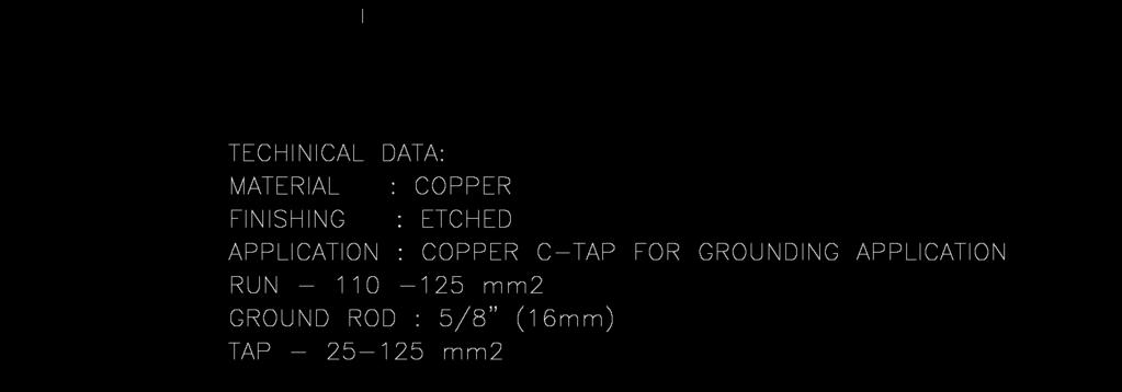
19 5.5.8 The contours, edges and corners of the hardware fittings shall be rounded to eliminate areas of high corona stress concentration Split cotter keys shall be humped to maintain the key in the locked or unlocked positions and shall have prongs spread to prevent withdrawal from the socket Each hardware fitting shall bear a marking identifying the Manufacturer s Name or trademark, Manufacturer s Catalog number, Strength Rating and Year of manufacture The preformed ties and preformed armor rods shall be made of aluminum alloy material compatible with the ACSR/AW conductors to which they will be applied. The lay direction of preformed helical rods shall be the same as that of the outer layer of the conductor to which it is applied. The preformed ties and armors shall be provided with identification label showing the manufacturer s catalog number, insulator details and conductor diameter range The stainless steel strap and the semi rigid PVC sleeve shall be supplied in a handy weather proof packaging, and shall be in rolls of 50 meters each. 5.6 CONNECTORS The types of connectors shall be as specified in Data Schedule of this Specification. The types of connectors are, but not limited to, full tension sleeve, repair sleeve, insulated sleeve, parallel groove compression connector, terminal lug, terminal plug, copper crimpit and ground rod clamp The connectors shall be designed to conform to the type, size and ampacity ratings of the conductors joined The tensile rating of the full tension sleeve shall be ninety five percent (95%) of the applicable ASTM rated strength of the weaker of the conductors being joined The tensile rating of the minimum tension connector such as the insulated sleeve, parallel groove compression connector, terminal lug, terminal plug, C-Tap and ground rod clamp shall be five percent (5%) of the applicable rated strength rating of the weaker conductors being joined, but not less than 889 Newtons for conductor larger than mm². Page 19 of 105
20 5.6.5 The full tension shall be compression type and made of aluminum anodic oxide coated in accordance with ASTM B The full tension sleeve for ACSR/AW conductors shall be one-piece compression type and shall be pre-filled with filler (oxide inhibiting or sealing) compound and capped The repair sleeve shall be compression type, made of cast aluminum and U-shaped The parallel groove connector shall be compression type made of high conductivity aluminum, H-shaped, with bendable tabs to secure conductors and pre-filled with filler (oxide inhibiting or sealing) compound and individually packed The terminal lug for ACSR or aluminum conductors shall be compression type and made of tin plated aluminum. The connector bores shall be pre-filled with filler (oxide inhibiting or sealing) compound and capped, as per latest revision of 12- SDMS-02 Cable Lugs and Connectors The terminal plug for ACSR or aluminum conductors shall be compression type and made of aluminum with tin plated copper plug. The connector bores shall be prefilled with filler (oxide inhibiting or sealing) compound and capped. The plug shall be bendable to desired angle for easier insertion to equipment terminals The insulated sleeve shall be compression type and made of aluminum connector with nylon jacket to insulate electrically and protect against water and weather. The barrel of connector sleeve shall be pre-filled with filler (oxide inhibiting or sealing) compound and furnished with polyethylene cap The crimpit connector shall be C-shaped compression type and made from pure annealed 99.9% copper per EN 13605, DIN 40500, or equivalent The ground rod clamp shall be mechanical type connector with U-bolt and hexagonal nut made of Silicon Bronze with Copper Alloy UNS No. C per ASTM B98, body made of Phosphor Bronze with Copper Alloy UNS No. C per ASTM B139 and ASTM B140, round washer made of Copper Plated Brass, and the spring washer made of Stainless Steel Grade SS To facilitate proper identification during installation, the Manufacturer s Name or trademark, Manufacturer s Catalog number, Die Index Number, Conductor Size, Knurl Locations and Start/Stop Knurl shall be marked in legible and indelible on each connector: Page 20 of 105
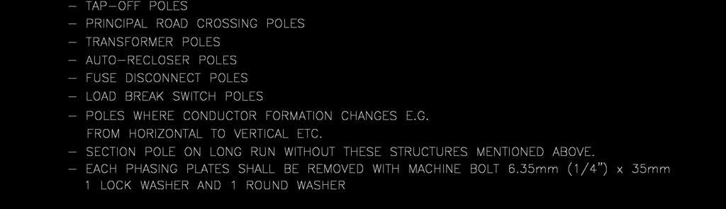
21 5.7 ANTI-CLIMBING DEVICE The anti-climbing device shall be of the type shown in Fig. No The nominal diameter of the barbed wire strand shall be 2.5 +/- 0.1 mm. The barbed wire shall have a minimum breaking strength of 4.23 kn The barbed wire shall be carbon steel in accordance with ASTM A510, Grade 1040 and galvanized as per ASTM A Barbed wire shall consist of two (2) twisted strands with four (4) barbs (points) spaced not more than 125 mm apart. Strand wires shall be twisted with uniform length of lay. The direction of twisting may be in one direction or alternatively in left and right direction Barbs (points) length measured from the center of the two (2) strand wires shall be 9.5 mm (minimum) The barbed wire shall be packaged on spools of 300 meters in length. 5.8 GROUNDING RODS AND EARTH ELECTRODE The grounding rods provided under this specification shall be sectional type. The rods are rolled threaded at each end and can be joined together with couplings The grounding rod shall be made of solid steel core bonded uniformly with copper through electrolytic process. The copper shall be bonded with the steel core using suitable substrate such as nickel or any other material to ensure adherence. The steel core shall not be less than 98% iron and when tested in accordance to ASTM A370 shall have mechanical tensile strength of not less than N/mm². The copper coating shall not be less than 99.5% pure copper with minimum coating thickness of 0.25 mm as per ASTM E The grounding rod coupling shall be made of Silicon Aluminum Bronze with Copper Alloy UNS No. C per ASTM B150 and ASTM B249, counter bored to enclose fully the threads on the rods. The design shall ensure that when assembled, there will be direct rod-to-rod contact when the rod driving force is applied. Page 21 of 105
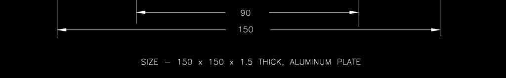
22 5.8.4 The grounding rod driving head shall be of high strength steel Grade 8.8 complying to applicable requirements of ASTM 325M, threaded to fit the grounding rod coupling. The design shall ensure that there is direct driving head to rod contact when the rod driving force is applied. The driving head shall be suitable for re-use The grounding rod, grounding rod coupler, and driving head shall be supplied together as one item. 5.9 DANGER, NUMBERING AND PHASING PLATES The danger, numbering and phasing plates shall be manufactured from flat sheet aluminum to BS The danger sign plate for MV equipment shall show a white skull and crossbones and DANGER HIGH VOLTAGE in Arabic and English marking on red background on 150 mm x 150 mm x 1.5 mm aluminum plate as shown in Fig. No The danger sign plate for LV equipment shall be manufactured on 100 mm x 100 mm x 1.5 mm aluminum plate as shown in Fig. No. 49A The numbering plates shall consist of a number tag holder and number tags as shown in Fig. No. 51. The number tag holder shall be black painted aluminum size 400 mm (maximum) x 50 mm x 1 mm and shall be provided with flanges to accommodate the 48 mm x 20 mm tags. The number plates shall be yellow painted aluminum size 48 mm x 20 mm with the cut through numbers or letters The phasing plates shall be 80 mm diameter x 1.5 to 2.0 mm thick and with black colored letters A, B or C on Red, Yellow or Blue background, respectively, as shown in Fig. No Paint shall be high gloss baked enamel finish. This shall include a transparent lacquer capable of blocking the ultraviolet rays of sun and preventing their discoloring influence The plates shall have rounded corners and no sharp or rough edges. Page 22 of 105
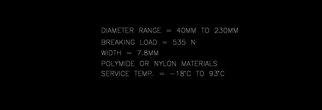
23 5.10 NON-METAL ACCESSORIES The other accessories included in this Specification are guy wire guard, ground wire guard and flexible conduit The guy wire guard shall be half-round and yellow colored, made of ultra-violet stabilized and high impact resistance PVC. The guy wire guard shall be furnished with galvanized steel clamps located at the top, the middle and lower end for attachment to 12 mm diameter stay wire strand as shown in Fig. No The ground wire guard shall be made of rigid, high impact PVC formulation and the dimensions are as shown in Fig. No The flexible conduit shall be made of halogen-free, UV resistant polyamide, as shown in Fig. No. 62, 62A, and 62B The flexible conduit should be in compliance with mechanical requirements according to IEC EN 61386, minimum temp of the thermal properties should be not less than 100 C The Thermo Plastic pipes such as PVC, PE, or equivalent material shall be plain, Gray in color, weather resistant, dimensions as shown in Fig. No. 59A, minimum temp of the thermal properties should be not less than 90 C The cable tie shall be self-locking type and made of nylon. 6.0 INSPECTION AND TESTING In addition to the requirements specified in 01-SDMS-01, the following shall be fulfilled: 6.1 The Supplier shall make adequate routine and tests and inspections to determine the conformity of material furnished under this Specification with the requirements invoked. 6.2 Inspection/Routine Test Requirements Inspection/routine tests shall be in accordance with the applicable standards in this specification Visual inspection shall include checks for satisfactory workmanship, materials, freedom from surface defects and for compliance with the Purchase Order and the General Specifications. Page 23 of 105
24 6.2.3 SEC or its designated representative may conduct acceptance inspection and witness testing at the manufacturer's plant or conduct testing at SEC facilities SEC designated representative shall have free access at any time while work is being carried on, to all areas of the Supplier's plant, which concern the work Inspection/routine tests may be made during all stages of manufacturing and shipping SEC or its designated representative may conduct acceptance inspection at manufacturer's plant or upon delivery at site. Also, SEC or its designated representative may witness testing at manufacturer's plant or conduct the testing at SEC facilities. However, inspection and acceptance shall not relieve the Supplier of his responsibility for conformance with this specification. 6.3 Type Testing Requirements All materials shall be type tested, in an Independent Testing Laboratory or at manufacturer s laboratory witnessed by SEC designated representative, in accordance with the requirement of the latest standards in this specification. Following the completion of all tests, two certified copies of the test reports, including the mill test certificate demonstrating that the materials used meets the requirements of the referenced standards in this specification, shall be submitted to SEC for review and approval. The following type tests shall be carried out: Galvanizing tests in accordance with ASTM or ISO or equivalent standards referenced in this specification shall be carried out for all galvanized materials, including the threads of the bolts Dimensional and Visual tests for samples of each finished article Mechanical failing load tests for machine bolts, shoulder eyebolts, anchor rods, anchor shackle, clevis eye extension, strain clamps, suspension clamps Overhead line fittings such as strain clamps, suspension clamps, full-tension compression sleeve, etc., shall be tested in conformance with IEC Page 24 of 105
25 6.3.5 Stay Wire - Test for mechanical properties of component wires shall be made before stranding. Tension and torsion tests shall be made on the finished strand Mechanical strength tests and heat cycle tests for tension connectors (full tension sleeves) and heat cycle tests for non-tension connectors (C-Tap compression and ground connector) Jacket adherence test and bend test for grounding rod Tensile strength test to BS 1470 and flexibility test for danger, number and phasing plates The connection components shall be tested as per IEC Earth electrodes and conductors shall be tested as per IEC For physical damages and life hazards the tests shall be done as per IEC Power installation at voltage level exceeding 1 kv. Shall be as per CENELEC HD 637S Code of practice for earthing shall be as per BS 7430 be applied Grounding and bonding of equipments for safety shall be as per UL Chemical composition as per BS 1432/ Flexible non metallic conduit systems as per IEC EN 61386, EN 50086, DIN and UL PACKING AND SHIPMENT In addition to the packing and shipping requirements specified in 01-SDMS-01, the following shall be fulfilled: 7.1 Items consisting of two or more parts such as bolts with nuts and washers shall be delivered, as far as possible, fully assembled/packed as one set. Page 25 of 105
26 7.2 The stay wire shall be furnished in lengths shown in the Data Schedule and packed in wooden or steel reals and lagged externally. Wood lagging or better material shall be secured with steel straps to provide physical protection during transit and customary storage and handling operations. 8.0 GUARANTEE 8.1 The vendor shall guarantee the materials against all defects arising out of faulty design or workmanship for a period of one year from the date of commissioning or two years from date of delivery. SEC certificates for date of commissioning shall be accepted. 8.2 If no exceptions to this specification are taken and no list of deviations is submitted, it shall be deemed that, in every respect, all items offered shall conform to this Specification. SEC interpretation of this Specification shall be accepted. 9.0 SUBMITTALS 9.1 In addition to documentations specified in 01-SDMS-01, the following shall be submitted by the vendor/manufacturer: Detailed working drawings necessary for fabrication shall be supplied with the proposals in case SEC drawing is not available. The drawing shall include but not limited to the following: a) The complete dimensions and location of bolt holes. b) Details of connections, bends, shaping and cuts. c) Details of identification marks or numbers. d) Type tests and routine tests reports for metallic and non metallic products shall be submitted during evaluation of tender Submittals required following award of contract: a. Drawings for final SEC approval shall be submitted prior to start of manufacturing. Supplier shall furnish all final drawings in original as well as on digital DWG format. b. Manufacturing schedule, progress report and test schedules. Page 26 of 105
27 c. Test reports including, but not limited to, the following: Certified mill test reports for all material. Certified welding reports, if applicable. Test reports on coating thickness, nuts & bolts and reports on dimensional checks. Report of all material testing, when required, including photos, diagrams, etc. Page 27 of 105
28 10.0 DATA SCHEDULE OVERHEAD LINE ACCESSORIES (Sheet 1 of 10) SEC Inquiry No. Item No. REF. SEC- TION DESCRIPTION SEC SPECIFIED VALUES VENDOR PROPOSED VALUES 5.2 FABRICATED STEEL SHAPES AND PLATES Name/Description of Fabricated Material SEC Fig. No. Manufacturer s Drawing No. Manufacturer s Catalog No Shape of Steel Material Standard Designation/Grade of Steel Minimum Yield Stress of Steel Material, 250 N/mm² Dimensions (mm) Strength Rating (kn) Galvanize Coating Weight, g/m² Grade of Component Machine Bolts and Cotter Pins Component Machine Bolts Galvanize Coating 381 Weight, g/m² Component Cotter Keys Stainless Steel Manufacturing Standard Specification Total Weight (after galvanization) Quantity Required Page 28 of 105
29 10.0 DATA SCHEDULE OVERHEAD LINE ACCESSORIES (Sheet 2 of 10) SEC Inquiry No. Item No. REF. SEC- TION DESCRIPTION SEC SPECIFIED VALUES VENDOR PROPOSED VALUES 5.3 BOLTS, NUTS AND WASHERS Type of Bolt SEC Fig. No. Manufacturer s Drawing No. Manufacturer s Catalog No Diameter, mm Length, mm Threaded Length, mm Coarse of Thread Eye Size (Shoulder Eyebolt and Eye nut) Grade or Strength Rating Galvanize Coating Weight, g/m² Number of Nuts Number of Washers Manufacturing Standard Specification Markings Quantity Required Page 29 of 105
30 10.0 DATA SCHEDULE OVERHEAD LINE ACCESSORIES (Sheet 3 of 10) SEC Inquiry No. Item No. REF. SEC- TION DESCRIPTION SEC SPECIFIED VALUES VENDOR PROPOSE D VALUES 5.3 ANCHOR RODS Type of Anchor Rod SEC Fig. No. Manufacturer s Drawing No. Manufacturer s Catalog No Diameter, mm Length, mm Material Galvanized Steel Length of Thread Eye Dimensions Strength Rating, kn Galvanize Coating Weight, g/m² Number of Nuts Markings Manufacturing Standard Specification Quantity Required Page 30 of 105
31 10.0 DATA SCHEDULE OVERHEAD LINE ACCESSORIES (Sheet 4 of 10) SEC Inquiry No. Item No. REF. SEC- TION DESCRIPTION SEC SPECIFIED VALUES VENDOR PROPOSED VALUES 5.4 STAY WIRE STRAND Nominal Diameter of Strand, mm Number of Wires in Strand Nominal Diameter of Individual Wires, mm Minimum Breaking Strength, kn Material Galvanized Steel Galvanize Coating Weight, g/m² Lay Direction Left Hand Manufacturing Standard Specification. Type of Reel Length per Reel Page 31 of 105
32 10.0 DATA SCHEDULE OVERHEAD LINE ACCESSORIES (Sheet 5 of 10) SEC Inquiry No. Item No. REF. SEC- TION DESCRIPTION SEC SPECIFIED VALUES VENDOR PROPOSED VALUES PREFORMED GUY GRIP Compatible With 12.0 mm Stay Wire Strand Yes Nominal Diameter Material Galvanized Steel Construction Form Preformed Helical Rods Number of Helical Rods per Set Diameter of Rods, mm Lay Direction Left Hand Applied Length, mm Holding Strength Rating Galvanize Coating Weight, g/m² Markings Manufacturer s Catalog No. Quantity Required Page 32 of 105
33 10.0 DATA SCHEDULE OVERHEAD LINE ACCESSORIES (Sheet 6 of 10) SEC Inquiry No. Item No. REF. SEC- TION DESCRIPTION SEC SPECIFIED VALUES VENDOR PROPOSED VALUES 5.5 INSULATOR AND CONDUCTOR HARDWARE FITTINGS Hardware Fitting Type SEC Fig. No. Manufacturer s Drawing No. Manufacturer s Catalog No Material Dimensions (mm) Cotter Pin Diameter, mm Cotter Key Stainless Steel Strength Rating (kn) Galvanize Coating Weight, g/m² 610 Manufacturing Standard Specification Markings Total Weight (after galvanization) Quantity Required Page 33 of 105
34 10.0 DATA SCHEDULE OVERHEAD LINE ACCESSORIES (Sheet 7 of 10) SEC Inquiry No. Item No. REF. SEC- TION DESCRIPTION SEC SPECIFIED VALUES VENDOR PROPOSED VALUES 5.6 CONNECTORS Connector Type SEC Fig. No. Manufacturer s Drawing No. Manufacturer s Catalog No Associated Conductor Material Associated Conductor Cross Sectional Area Associated Conductor Diameter Material of Connector Dimensions (Before Compression), mm Associated Conductor Size Die Index Number Mechanical Strength Rating (kn) Current Rating (Amperes) Manufacturing Standard Specification Quantity Required Page 34 of 105
35 10.0 DATA SCHEDULE OVERHEAD LINE ACCESSORIES (Sheet 8 of 10) SEC Inquiry No. Item No. REF. SEC- TION DESCRIPTION SEC SPECIFIED VALUES VENDOR PROPOSED VALUES 5.8 GROUNDING RODS Type of Grounding Rod Sectional SEC Fig. No. Manufacturer s Drawing No. Manufacturer s Catalog No. Diameter, mm Length, mm Material Copper Bonded Steel Thickness of Copper Coating, mm Length of Threaded Ends Grounding Rod Coupling Material Silicon Aluminum Bronze Grounding Rod Coupling Length, mm Grounding Rod Driving Head Material High Strength Steel Grounding Rod Driving Head Length, mm 40 Manufacturing Standard Specification Markings Quantity Required Page 35 of 105
36 10.0 DATA SCHEDULE OVERHEAD LINE ACCESSORIES (Sheet 9 of 10) SEC Inquiry No. Item No. REF. SEC- TION DESCRIPTION SEC SPECIFIED VALUES VENDOR PROPOSED VALUES 5.9 DANGER, NUMBERING AND PHASING PLATES Type of Sign Plate (Danger, Numbering or 5.9 Phasing) SEC Fig. No. Manufacturer s Drawing No. Manufacturer s Catalog No Material Fixing Dimensions Paint Finish Manufacturing Standard Specification Quantity Required High Gloss Baked Enamel Page 36 of 105
37 10.0 DATA SCHEDULE OVERHEAD LINE ACCESSORIES (Sheet 10 of 10) A. ADDITIONAL TECHNICAL INFORMATION OR FEATURES SPECIFIED BY SEC: B. ADDITIONAL SUPPLEMENTARY DATA OR FEATURES PROPOSED BY BIDDER/VENDOR/SUPPLIER: C. OTHER PARTICULARS TO BE FILLED UP BY BIDDER/VENDOR/ SUPPLIER: D. LIST OF DEVIATIONS & CLAUSES TO WHICH EXCEPTIONS ARE TAKEN BY THE BIDDER/VENDOR/SUPPLIER: (USE SEPARATE SHEET IF NECESSARY) MANUFACTURER OF MATERIALS/EQUIPMENT VENDOR / SUPPLIER Name of Company Location and Office Address Name and Signature of Authorized Representative Official Seal / Stamp Page 37 of 105
38 FIG. 1: CROSSARM L 100x100x12x2400 mm L.G. ( ) Page 38 of 105

 Page 39")
39 FIG. 2: FUSE CUTOUT MOUNTING CHANNEL FOR H-POLE PMT ( ) Page 39 of 105
40 FIG. 2A: FUSE CUTOUT MOUNTING CHANNEL FOR SINGLE-POLE PMT ( ) Page 40 of 105
 Page 41 of")
41 FIG. 3: TRANSFORMER MOUNTING CHANNEL ( ) Page 41 of 105
42 FIG. 4: BRACE-SET 2L 50x50x4x828 mm L.G. FOR MV POLES ( ) Page 42 of 105
43 FIG. 4A: BRACE-SET 2L 50x50x4x828 mm L.G. FOR SINGLE POLE PMT ( ) Page 43 of 105

 Page 44")
44 FIG. 5: EARTHWIRE SUSPENSION SUPPORT-L 120x120x10x150 mm L.G. ( ) Page 44 of 105


45 FIG. 6: EARTHWIRE SUPPORT ASSEMBLY ( ) Page 45 of 105
46 FIG. 7: DOUBLE ARMING PLATE-L 100x12x700 mm L.G. ( ) Page 46 of 105
 Page")
47 FIG. 8: HORIZONTAL INSULATOR MOUNTING BRACKET ( ) Page 47 of 105
48 FIG. 9: SPOOL INSULATOR BRACKET ( ) Page 48 of 105
 190 (908202213)")
 242 (908202087)")
 FOR OCTAGONAL STEEL")
49 106 ( ) 166 ( ) 190 ( ) 210 ( ) 234 ( ) 242 ( ) FIG. 10: POLE BAND (STAY CLAMP) FOR OCTAGONAL STEEL POLE Page 49 of 105
50 WIRE DIA. (MIN.) BARBS SPACING (MAX.) BARBS SIZE BARBS TYPE d1 d2 L1 L2 DOUBLE TWISTED MIN. BREAKING STRENGTH 4.23 kn NOTE: MATERIAL GALVANIZED CARBON STEEL FIG. 13: ANTI-CLIMBING BARBED WIRE ( ) Page 50 of 105
51 FIG. 13A: BUCKLE LOCKING CLIP FOR BARBED WIRE ( ) Page 51 of 105

52 MACHINE BOLT-M16 LENGTH SEC ITEM CODE FIG. 14: MACHINE BOLT M16 Page 52 of 105

53 MACHINE BOLT-M20 LENGTH SEC ITEM CODE FIG. 15: MACHINE BOLT M20 Page 53 of 105
54 SHOULDER EYEBOLT-M16 LENGTH SEC ITEM CODE FIG. 16: SHOULDER EYEBOLT M16 Page 54 of 105
55 SHOULDER EYEBOLT-M20 LENGTH SEC ITEM CODE FIG. 17: SHOULDER EYEBOLT M20 Page 55 of 105
 Page 56 of")
56 FIG. 18: EYE NUT FOR M16 ( ) Page 56 of 105
 Page 57 of")
57 FIG. 19: EYE NUT FOR M20 ( ) Page 57 of 105

")
58 FIG. 20: ANCHOR SHACKLE ( ) Page 58 of 105
59 FIG. 21: CLEVIS EYE EXTENSION ( ) Page 59 of 105
60 ANCHOR ROD DIAMETER ANCHOR ROD LENGTH UTS MIN. THIMBLE EYE TYPE SEC ITEM CODE KN THIMBLE EYE KN THIMBLE EYE FIG. 22: ANCHOR ROD THIMBLE EYE WITH TURN BUCKLE (ADJUSTABLE) 16 & 19 mm DIAMETER Page 60 of 105
61 ANCHOR ROD DIAMETER ANCHOR ROD LENGTH UTS MIN. THIMBLE EYE TYPE SEC ITEM CODE KN TWIN EYE KN TWIN EYE FIG. 22A: ANCHOR ROD TWIN EYE WITH TURN BUCKLE (ADJUSTABLE) 19 & 24 mm DIAMETER Page 61 of 105


62 STAY PLATE DIMENSION STAY PLATE HOLE DIAMETER (Ø) SEC ITEM CODE 450 x 450 x 6 THK x 450 x 10 THK x 450 x 10 THK FIG. 23: STEEL PLATE H.D.G. FOR ANCHOR RODS Page 62 of 105
63 FOR STAY WIRE DIA. RANGE (MIN.-MAX) APPROX. LENGTH (L) ±30mm NUMBER OF STRANDS STRAND DIA. (d) MINIMUM BREAKING LOAD COLOR I.D. CODE SEC ITEM CODE 7/4, 12 mm DIA kn RED /3.25, 9.8mm DIA kn YELLOW FIG. 26: PREFORMED GUY GRIP (DEAD END GRIP) Page 63 of 105


64 FIG. 27: GUY THIMBLE ( ) Page 64 of 105
 Page 65 of 105")
65 FIG. 28: GUY WIRE GUARD, YELLOW COLOR, 2.44 METERS ( ) Page 65 of 105
66 CONDUCTORS NAME DIA. CLAMP DIMENSIONS U-BOLT A B C D E d R No. SIZE UTS (kn) MIN. SEC ITEM CODE QUAIL MERLIN FIG. 29: STRAIN CLAMPS, 3 U-BOLTS TYPE Page 66 of 105
67 CLAMP UTS U-BOLT SEC ITEM CONDUCTOR DIAMETER DIMENSION (kn) CODE NO. SIZE A B C MIN. QUAIL QUAD-MESSENGER FIG. 30: STRAIN CLAMP, STRAIGHT LINE DEAD-END (2 U-BOLT TYPE) Page 67 of 105


68 CONDUCTOR DIAMETER CLAMP DIMENSIONS A B C D UTS (kn) MIN. SEC ITEM CODE QUAIL MERLIN QUADRUPLEX 120 mm² MESSENGER FIG. 31: SUSPENSION CLAMP Page 68 of 105


69 CONDUCTOR DETAILS NAME O.D. ØA ØB LENGTH MIN. UTS (kn) MIN. SEC ITEM CODE MERLIN QUAIL QUAD. MESSENGER FIG. 32: FULL TENSION COMPRESSION SLEEVE (MID-SPAN JOINT) W/O STEEL SLEEVE Page 69 of 105
70 CONDUCTOR DETAILS NAME O.D. ØA ØB LENGTH MIN. TYPE UTS (kn) MIN. SEC ITEM CODE MERLIN A QUAIL B QUAD. MESSENGER A FIG. 33: REPAIR SLEEVES Page 70 of 105

 FOR CONNECTING")
71 CONDUCTOR SIZE SIDE A SIDE B LENGTH (L) SEC ITEM CODE 120 mm² 120 mm² 150 mm mm² 50 mm² 150 mm mm² 50 mm² 100 mm FIG. 34: INSULATED TYPE SLEEVE (NON-TENSION) FOR CONNECTING QUADRUPLEX CABLES Page 71 of 105

72 CONDUCTOR DETAILS NAME O.D. ROD DIA. LENGTH (L) NO. OF STRANDS COLOR CODE REMARKS SEC ITEM CODE MERLIN WHITE W/O ARMOR ROD MERLIN GREEN WITH ARMOR ROD QUAIL BLUE W/O ARMOR ROD QUAIL RED WITH ARMOR ROD FIG. 35: PREFORMED LINE POST INSULATOR TOP TIE Page 72 of 105
73 CONDUCTOR DETAILS NAME O.D. ROD DIA. LENGTH (L) NO. OF STRANDS COLOR CODE REMARKS SEC ITEM CODE MERLIN WHITE W/O ARMOR ROD MERLIN GREEN WITH ARMOR ROD QUAIL BLUE W/O ARMOR ROD QUAIL RED WITH ARMOR ROD FIG. 36: PREFORMED LINE POST INSULATOR SIDE TIE Page 73 of 105

")
74 FIG. 37: SPOOL INSULATOR SIDE TIE ( ) Page 74 of 105
 DESCRIPTION APPROXIMATE APPLIED LENGTH (L) NUMBER OF RODS COLOR CODE")

75 CONDUCTOR ACSR/AW CONDUCTOR RANGE, DIA. (Ø) AREA mm² ROD DIA. (d) DESCRIPTION APPROXIMATE APPLIED LENGTH (L) NUMBER OF RODS COLOR CODE SEC ITEM CODE MERLIN BLUE QUAIL YELLOW FIG. 38: PREFORMED ARMOR RODS Page 75 of 105


76 CONDUCTOR DIMENSIONS GROOVE A GROOVE B H L W SEC ITEM CODE MERLIN MERLIN MERLIN QUAIL QUAIL QUAIL QUADRUPLEX MESSENGER 4x120 mm² AL. QUADRUPLEX MESSENGER 4x120 mm² AL. QUADRUPLEX MESSENGER 4x120 mm² AL. QUADRUPLEX MESSENGER 4x50 mm² AL FIG. 39: PARALLEL GROOVE COMPRESSION TYPE CONNECTORS Page 76 of 105

77 CONDUCTOR DIMENSIONS MIN. BOLTS GROOVE A GROOVE B L W NOS. DIA. SEC ITEM CODE MERLIN MERLIN MERLIN QUAIL QUAIL QUAIL FIG. 39A: PARALLEL GROOVE CONNECTOR BOLTED TYPE Page 77 of 105


")
78 FIG. 40: LV CONNECTOR COVER (INSULATING CAP) ( ) Page 78 of 105

79 CONDUCTOR DIMENSIONS A P L D E d1 d2 R SEC ITEM CODE MERLIN QUAIL FIG. 42: TERMINAL PLUG Page 79 of 105
80 LENGTH OF GROUND ROD, NOMINAL DIA 16 mm SEC ITEM CODE 1200 mm mm FIG. 43: GROUNDING ROD, 16 mm DIAMETER Page 80 of 105
 Page 81")
81 FIG. 44: GROUND ROD CLAMP U-BOLT TYPE ( ) Page 81 of 105


82 FIG. 45: CRIMPIT COPPER CONNECTOR ( ) Page 82 of 105
83 FIG. 46: 35 mm² FLEXIBLE MULTI-STRANDED COPPER WIRE ROPE mm LENGTH WITH TIN-PLATED COPPER LUGS ( ) Page 83 of 105

")
84 FIG. 47: PVC GROUND WIRE GUARD ( ) Page 84 of 105


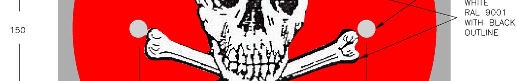
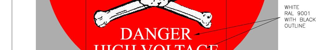
85 FIG. 49: DANGER SIGN PLATE FOR MEDIUM-VOLTAGE EQUIPMENT ( ) Page 85 of 105


86 ALUMINUM PLATE: 1.5 mm THICK FIG. 49A: DANGER SIGN PLATE FOR LOW-VOLTAGE EQUIPMENT Page 86 of 105
87 FIG. 50: DANGER SIGN MOUNTING BRACKET ( ) Page 87 of 105
 Page 88")
88 FIG. 51: POLE NUMBERING PLATES ( ) Page 88 of 105
 Page 89 of")
89 FIG. 52: EQUIPMENT NUMBERING PLATES ( ) Page 89 of 105


90 FIG. 53: PHASING PLATES ( ) Page 90 of 105
91 FIG. 54: PHASING PLATES MOUNTING BRACKET ( ) Page 91 of 105
 Page 92 of")
92 FIG. 55: STAINLESS STEEL STRAP ( ) Page 92 of 105
93 FIG. 55A: STAINLESS STEEL BUCKLE LOCKING CLAMP (EAR-TYPE) FOR STAINLESS STEEL STRAP ( ) Page 93 of 105
94 FIG. 55B: SEMI-RIGID PVC SLEEVE FOR STAINLESS STEEL STRAP ( ) Page 94 of 105

 Page")
95 FIG. 56: WEDGE GRIP WITH REMOVABLE BAIL ( ) Page 95 of 105
 Page 96")
96 FIG. 57: SERVICE MAST CLAMP FOR 76 mm DIAMETER STEEL PIPE ( ) Page 96 of 105
 Page 97 of")
97 FIG. 58: SERVICE ENTRANCE HEAD FOR MAST 76 mm DIAMETER STEEL PIPE ( ) Page 97 of 105
98 FIG. 59: SERVICE DROP STEEL PIPES (70 mm INSIDE DIAMETER) WITH 3.0 mm MINIMUM THICKNESS, ±5% TOLERANCE ( ) Page 98 of 105

99 FIG. 59A: PVC/PE PIPE FOR PMT STRUCTURE H & S (75 mm OUTSIDE DIAMETER) WITH 3.6 mm MINIMUM THICKNESS, ±5% TOLERANCE ( ) Page 99 of 105
100 FIG. 60: SERVICE MAST ON-WALL SUPPORT CLAMP ( ) Page 100 of 105
101 FIG. 61: SERVICE MAST THROUGH WALL SUPPORT CLAMP ( ) Page 101 of 105
 Page 102 of")
102 FIG. 62: FLEXIBLE CONDUIT FOR 76 mm OUTER DIAMETER SERVICE STEEL PIPE WITH LOCK NUT AND CLAMP ( ) Page 102 of 105
103 LENGTH, METERS SIZE OF INCOMING CABLE SEC ITEM CODE 2 4 x 300 mm² x 185 mm² FIG. 62A: FLEXIBLE CONDUIT 75 mm INSIDE DIAMETER WITH COUPLING NUTS FOR INCOMING CABLE Page 103 of 105
104 LENGTH, METERS SIZE OF OUTGOING CABLE SEC ITEM CODE x 120 mm² x 120 mm² FIG. 62B: FLEXIBLE CONDUIT 76 mm OUTSIDE DIAMETER WITH COUPLING NUTS FOR OUTGOING CABLE Page 104 of 105


105 FIG. 63: CABLE TIES ( ) Page 105 of 105
20-SDMS-02 REV. 03 ( )
") 20-SDMS-02 REV. 03 (27-05-2018) SPECIFICATION FOR OVERHEAD LINE ACCESSORIES Saudi Electricity Company 1. SCOPE... 3 2. CROSS REFERENCES... 3 3. APPLICABLE CODES AND STANDARDS... 3 4. SERVICE CONDITIONS
20-SDMS-02 REV. 03 (27-05-2018) SPECIFICATION FOR OVERHEAD LINE ACCESSORIES Saudi Electricity Company 1. SCOPE... 3 2. CROSS REFERENCES... 3 3. APPLICABLE CODES AND STANDARDS... 3 4. SERVICE CONDITIONS
GURANTEED TECHNICAL PARTICULARS OF BACK CLAMP FOR LT CROSS ARM
 Technical Specification of Back Clamp for LT Cross Arm (MS) Back clamp for LT Cross Arm made out of 50 x 6mm MS Flat suitable for 8m X 300 Kg PSC poles. After fabrication the cross arm shall be painted
11-SDMS-03 REV. 02 SPECIFICATIONS FOR
 11-SDMS-03 REV. 02 SPECIFICATIONS FOR XLPE INSULATED POWER CABLES FOR RATED VOLTAGES FROM 15 KV UP TO 36 KV (U m ) This specification is property of SEC and subject to change or modification without notice
PART MATERIALS. Section Fencing Materials. Description
 PART 03000 - MATERIALS Section 03010 - Fencing Materials Description 03010.00 Scope - This section consists of the test requirements, specifications and tolerances for barbed wire, woven wire and chain
SECTION METAL FABRICATIONS
 SECTION 05100 PART 1 - GENERAL 1.01 DESCRIPTION A. Section includes specifications for metal fabrications, including minimum requirements for fabricator, and galvanizing. 1.02 REFERENCE STANDARDS A. ASTM
Government Recognized Export House OHSAS 18001:2007 ISO 14001:2004 PED Approved Company.
 Government Recognized Export House OHSAS 800:200 ISO 400:2004 PED Approved Company. Phone : +9 22 44 (2 Lines) Fax : +9 22 289 4 Email : export@reliablepipes.com domestic@reliablepipes.com Designation:
Testing. Material testing will be according to applicable AASHTO, ASTM or Department methods as specified.
 907.01 Section 907. FENCING MATERIALS 907.01 General Requirements. Materials for use in fencing property, right-of-way and other installations must comply with this section. 907.02 Testing. Material testing
Ground Clamps Cable Tray
 commercial and industrial fittings: ing Fittings and Solderless Connectors Clamps Cable Tray Terminates ground wire to cable tray. For aluminum or copper conductors. 1 4 hex wrench tightens both tray and
Standard Specification for Carbon and Alloy Steel Nuts [Metric] 1
![Standard Specification for Carbon and Alloy Steel Nuts [Metric] 1](/thumbs/78/77316211.jpg "Standard Specification for Carbon and Alloy Steel Nuts [Metric] 1") Designation: A 563M 04 METRIC Standard Specification for Carbon and Alloy Steel Nuts [Metric] 1 This standard is issued under the fixed designation A 563M; the number immediately following the designation
Designation: A 563M 04 METRIC Standard Specification for Carbon and Alloy Steel Nuts [Metric] 1 This standard is issued under the fixed designation A 563M; the number immediately following the designation
MATERIAL AND EQUIPMENT STANDARD FOR METRIC TYPE FASTENERS (SCREWS, BOLTS, STUDS, NUTS AND WASHERS) ORIGINAL EDITION DEC. 1997
 ORIGINAL EDITION DEC. 1997") MATERIAL AND EQUIPMENT STANDARD FOR METRIC TYPE FASTENERS (SCREWS, BOLTS, STUDS, NUTS AND WASHERS) ORIGINAL EDITION DEC. 1997 This Standard is the property of Iranian Ministry of Petroleum. All rights
MATERIAL AND EQUIPMENT STANDARD FOR METRIC TYPE FASTENERS (SCREWS, BOLTS, STUDS, NUTS AND WASHERS) ORIGINAL EDITION DEC. 1997 This Standard is the property of Iranian Ministry of Petroleum. All rights
SECTION CABLE TRAYS FOR COMMUNICATIONS SYSTEMS
 SECTION 270536 - CABLE TRAYS FOR COMMUNICATIONS SYSTEMS PART 1 - GENERAL 1.1 RELATED DOCUMENTS A. Drawings and general provisions of the Contract, including General and Supplementary Conditions and Division
TENANT IMPROVEMENT 16 FEBRUARY WEST 27TH STREET, 4TH FLOOR 100% CD OWNER/BID ADD 1-03/08/2018
 SECTION 055000 - PART 1 - GENERAL 1.1 RELATED DOCUMENTS A. Drawings and general provisions of the Contract, including General and Supplementary Conditions and Division 01 Specification Sections, apply
015 : 1993 CEB STANDARD
 015 : 1993 CEB STANDARD UNGALVANIZED STAY ASSEMBLIES CEYLON ELECTRICITY BOARD SRI LANKA Specification for UNGALVANIZED STAY ASSEMBLIES CEB Standard 015 : 1993 CEYLON ELECTRICITY BOARD No. 50, Sir Chittampalam
AUDAS. Tel: Fax: No.259 Baichi north Rd.Haiyan.Zhejiang.
 Standard State SECTION A : SCREW THREAD Basic elements of screw thread design ANSI/ASME B1.7M Nomenclature.Definitions and letter symbols for screw thread ASME B1.1 Unified inch screw thread ( UN and UNF
50-SDMS-01 SPECIFICATIONS FOR
 SPECIFICATIONS FOR CURRENT TRANSFORMERS UP TO 36 KV This specification is property of SEC and subject to change or modification without any notice C O N T E N T S CLAUSE TITLE PAGE NO. ------------ --------
SECTION STRUCTURAL STEEL. A. PART A and DIVISION 1 of PART B are hereby made a part of this SECTION.
 SECTION 051200 PART 1 GENERAL 1.01 GENERAL REQUIREMENTS A. PART A and DIVISION 1 of PART B are hereby made a part of this SECTION. B. Examine all conditions as they exist at the project prior to submitting
Standard Specification for High-Strength Bolts for Structural Steel Joints [Metric] 1
![Standard Specification for High-Strength Bolts for Structural Steel Joints [Metric] 1](/thumbs/75/72528177.jpg "Standard Specification for High-Strength Bolts for Structural Steel Joints [Metric] 1") Designation: A 325M 00 METRIC An American National Standard Standard Specification for High-Strength Bolts for Structural Steel Joints [Metric] 1 This standard is issued under the fixed designation A 325M;
Designation: A 325M 00 METRIC An American National Standard Standard Specification for High-Strength Bolts for Structural Steel Joints [Metric] 1 This standard is issued under the fixed designation A 325M;
Khathij Industrial Fasteners
 Dear Sir/Madam, Khathij Industrial Fasteners This is Saqubar Sadique representing 'KHATHIJ INDUSTRIAL FASTENERS' from Chennai, India. We 'Khathij industrial fasteners' like to introduce us as a Stockist
NPS/001/010 Technical Specification for Fasteners and Fixings for Wood Pole Overhead Lines and General Construction Works
 Version:- 4.0 Date of Issue:- August 2014 Page 1 of 13 NPS/001/010 Technical Specification for Fasteners and Fixings for Wood Pole Overhead Lines and General Construction Works 1. Purpose The purpose of
NORMATIVE REFERENCES
 American National Standards Institute NORMATIVE REFERENCES ANSI C135.30 1988 (expired 1993) Zinc-Coated Ferrous Ground Rod Electrodes for Overhead or Underground Lines American Society for Testing and
012: 2015 CEB SPECIFICATION GALVANIZED STEEL WIRE (EXCEPT SHIELDING WIRE FOR TOWER LINE APPLICATION)
") 012: 2015 CEB SPECIFICATION GALVANIZED STEEL WIRE (EXCEPT SHIELDING WIRE FOR TOWER LINE APPLICATION) CEYLON ELECTRICITY BOARD SRI LANKA Telephone: +94 11 232 8051 Fax: +94 11 232 5387 CONTENTS Page 1.0
012: 2015 CEB SPECIFICATION GALVANIZED STEEL WIRE (EXCEPT SHIELDING WIRE FOR TOWER LINE APPLICATION) CEYLON ELECTRICITY BOARD SRI LANKA Telephone: +94 11 232 8051 Fax: +94 11 232 5387 CONTENTS Page 1.0
POLE LINE HARDWARE POLE LINE HARDWARE. HI-LINE UTILITY SUPPLY CO. Phone: Fax:
 146 MACHINE BOLTS w/ square nut Rolled threads; s six inches or longer have con-type points. Hot dip galvanized. 860412 3/8" 4.5" 3" 250 8706 6" 3" 100 8707 7" 3" 100 8708 1/2" 8" 4" 100 8710 10" 4" 50
C. Samples for Initial Selection: Manufacturer's color charts showing the full range of colors available.
 SECTION 105113 - METAL LOCKERS PART 1 - GENERAL 1.1 RELATED DOCUMENTS A. Drawings and general provisions of the Contract, including General and Supplementary Conditions and Division 01 Specification Sections,
NORMATIVE REFERENCES
 American National Standards Institute NORMATIVE REFERENCES ANSI C135.30 1988 (expired 1993) Zinc-Coated Ferrous Ground Rod Electrodes for Overhead or Underground Lines American Society for Testing and
Section COUPLINGS AND COUPLING ADAPTERS. This Section covers couplings and coupling adapters for ductile iron and steel pipe.
 PART 1 GENERAL 1.01 SUMMARY Section 15155 This Section covers couplings and coupling adapters for ductile iron and steel pipe. 1.02 MEASUREMENT AND PAYMENT A. No separate payment for Work performed under
MDOTProjectwise\Documents\Reference Documents\Traffic Reference\Statewide Special Details\Develop
 500 460 MDOTProjectwise\Documents\Reference Documents\Traffic Reference\Statewide Special Details\Develop Check if Applicable TRAFFIC SIGNAL SPECIAL DETAILS INDEX/CHECKLIST *One completed checklist required
METRIC FASTENERS 1520 METRIC FASTENERS
 1520 METRIC FASTENERS METRIC FASTENERS A number of American National Standards covering metric bolts, screws, nuts, and washers have been established in cooperation with the Department of Defense in such
Item 550 Chain Link Fence
 Item Chain Link Fence 1. DESCRIPTION 2. MATERIALS Furnish, install, remove, repair, or replace chain link fence and gates. Furnish certification from the chain link fence materials manufacturer stating
SPECIFICATION FOR SAFETY POLE SIGNS & ACCESSORIES
 KP/3CB/TSP/0/00 04-09-9 Page of 9 TABLE OF CONTENTS 0. Circulation List 0. Amendment Record FOREWORD. SCOPE. REFERENCES 3. TERMS AND DEFINITIONS 4. REQUIREMENTS 5. TESTS AND INSPECTION 6. MARKING, LABELLING
SPECIFICATION FOR HIGH STRENGTH STRUCTURAL BOLTS
 UDC 621.882.211 [669.14.018.291] IS : 3757-1985 (Reaffirmed 2003) Edition 3.2 (1989-07) Indian Standard SPECIFICATION FOR HIGH STRENGTH STRUCTURAL BOLTS ( Second Revision ) (Incorporating Amendment Nos.
PIPE/CONDUIT SUPPORTS
 PIPE/CONDUIT SUPPORTS Pipe/Conduit Clamps...102-105 Unicushion... 106 Pipe & Tubing (Cush-A-Clamp ) Clamps...107-110 Pipe Hangers... 111 Pipe Rollers...111-112 Pipe Brackets... 113 Reference Tables...114-120
Standard Specification for Quenched and Tempered Steel Bolts and Studs 1
 Designation: A 44 00 Standard Specification for Quenched and Tempered Steel Bolts and Studs This standard is issued under the fixed designation A 44; the number immediately following the designation indicates
SECTION EXPANSION FITTINGS AND LOOPS FOR HVAC PIPING
 SECTION 230516 - EXPANSION FITTINGS AND LOOPS FOR HVAC PIPING PART 1 - GENERAL 1.1 RELATED DOCUMENTS A. Drawings and general provisions of the Contract, including General and Supplementary Conditions and
Pole Line Hardware. Heavy-Duty Spool Rack (200 A) No. of Wires. Anti-Vibration Kit for Spool Rack. Heavy-Duty Spool Rack (400 A) No.
 No. of Wires. Anti-Vibration Kit for Spool Rack. Heavy-Duty Spool Rack (400 A) No.") Heavy-Duty Spool Rack (200 A) SS401E - SS802E - SS803E - SS804E No. of Wires Overall Length SS401E 1 9-1/2 300 136.3 10 SS802E 2 17-1/2 520 236.3 SS803E 3 25-1/2 780 354.5 5 SS804E 4 33-1/2 1040 472.7
Heavy-Duty Spool Rack (200 A) SS401E - SS802E - SS803E - SS804E No. of Wires Overall Length SS401E 1 9-1/2 300 136.3 10 SS802E 2 17-1/2 520 236.3 SS803E 3 25-1/2 780 354.5 5 SS804E 4 33-1/2 1040 472.7
001: 2007 CEB STANDARD
 001: 2007 CEB STANDARD ALUMINIUM RE-DRAW RODS FOR ELECTRICAL PURPOSES CEYLON ELECTRICITY BOARD SRI LANKA Specification for ALUMINIUM RE-DRAW RODS FOR ELECTRICAL PURPOSES CEB Standard 001: 2007 CEYLON ELECTRICITY
Thru Wall Floor Seals For New Installation
 The O-Z/Gedney Thruwall and Floor Seals provide a positive means of sealing pipe, conduit or tube where they pass through a concrete foundation of a structure below grade or below ground water level or
D. Thermally Sprayed Metallic Coating (Flame Spray): STD SPEC
: STD SPEC") STANDARD SPECIFICATION SECTION 05121 MISCELLANEOUS METALWORK PART 1 - GENERAL 1.01 DESCRIPTION This section includes materials, fabrication, and installation of structural steel, connecting bolts, pipes,
STANDARD SPECIFICATION SECTION 05121 MISCELLANEOUS METALWORK PART 1 - GENERAL 1.01 DESCRIPTION This section includes materials, fabrication, and installation of structural steel, connecting bolts, pipes,
SECTION STRUCTURAL STEEL FRAMING PART 1 - GENERAL 1.1 RELATED DOCUMENTS
 SECTION 05 12 00 - STRUCTURAL STEEL FRAMING PART 1 - GENERAL 1.1 RELATED DOCUMENTS A. Drawings and general provisions of the Contract, including General and Supplementary Conditions and Division 01 Specification
SDCS-03 DISTRIBUTION NETWORK GROUNDING CONSTRUCTION STANDARD (PART-II) OVERHEAD NETWORK GROUNDING. Rev. 01
 OVERHEAD NETWORK GROUNDING. Rev. 01") SEC DISTRIBUTION GROUNDING STANDARD SDCS-03 Part-II Rev.01 SDCS-03 DISTRIBUTION NETWORK GROUNDING CONSTRUCTION STANDARD (PART-II) OVERHEAD NETWORK GROUNDING Rev. 01 This specification is property of SEC
SEC DISTRIBUTION GROUNDING STANDARD SDCS-03 Part-II Rev.01 SDCS-03 DISTRIBUTION NETWORK GROUNDING CONSTRUCTION STANDARD (PART-II) OVERHEAD NETWORK GROUNDING Rev. 01 This specification is property of SEC
WESTERN WIRE PRODUCTS
 WESTERN WIRE PRODUCTS Celebra ng 100 years of Quality and Service 1914 2014 Thanks to our dedicated employees and customers we are celebra ng 100 years of being in business and we look forward to servicing
CONTENTS CABLE MANAGEMENT AND
 CONTENTS CABLE MANAGEMENT SECTION 9 SECTION 9 CABLE MANAGEMENT AND ASSOCIATED PRODUCTS.................................91 PIN CLIPS H335B SERIES.......................................92 COPPER EARTH RODS.........................................92
5/16" Flange nut. Bolt Keeper Plate (8" Sq. SYS.) (3) 1/2" x 3" Hex head connector zinc plated bolt w/ washers and nut. Anchor 3" sq. 7 Ga.
 (3) 1/2 x 3 Hex head connector zinc plated bolt w/ washers and nut. Anchor 3 sq. 7 Ga.") 2 1/2" x 2 1/2" x 10 Ga. 6" 5" 4" Variable Slipbase (8" Sq. SYS.) 5/16 Corner Bolt W/ nut 5/16" Flange nut Stub Insert (8" Sq. SYS.) Bolt Keeper Plate (8" Sq. SYS.) (3) 1/2" x 3" Hex head connector zinc
2 1/2" x 2 1/2" x 10 Ga. 6" 5" 4" Variable Slipbase (8" Sq. SYS.) 5/16 Corner Bolt W/ nut 5/16" Flange nut Stub Insert (8" Sq. SYS.) Bolt Keeper Plate (8" Sq. SYS.) (3) 1/2" x 3" Hex head connector zinc
MEFA mounting accessories
 MEFA mounting accessories Mounting accessories Base plates Page 5/2 Double holder Page 5/4 Height-adjustable suspensions Page 5/5 Pendular bolt joints Page 5/6 Trapeze hanger Page 5/7 Threaded hooks, distance
TECHNICAL SPECIFICATION FOR 11KV, 3C x95mm mm 2 AERIAL BUNCHED CABLES FOR OVERHEAD LINES (CROSSED LINKED POLYTHENE DRY GAS CURED)
") TECHNICAL SPECIFICATION FOR 11KV, 3C x95mm 2 + 80mm 2 AERIAL BUNCHED CABLES FOR OVERHEAD LINES (CROSSED LINKED POLYTHENE DRY GAS CURED) 1. SCOPE This specification covers requirements of, 3C x95mm 2 +
TECHNICAL SPECIFICATION FOR 11KV, 3C x95mm 2 + 80mm 2 AERIAL BUNCHED CABLES FOR OVERHEAD LINES (CROSSED LINKED POLYTHENE DRY GAS CURED) 1. SCOPE This specification covers requirements of, 3C x95mm 2 +
TECHNICAL SPECIFICATION FOR. CONTACT WIRE HARD-DRAWN COPPER 161mm2
 Engineering Specification Electrical TECHNICAL SPECIFICATION FOR CONTACT WIRE HARD-DRAWN COPPER 161mm2 Version: 2 Issued: May 2018 Owner: Engineering Approved by: Andrew Russack, Head of Engineering Electrical
Standard Specification for Steel Transmission Tower Bolts, Zinc-Coated and Bare 1
 Designation: A 94 0 Standard Specification for Steel Transmission Tower olts, Zinc-Coated and are This standard is issued under the fixed designation A 94; the number immediately following the designation
.1 Comply with the General Conditions of the Contract, Supplementary General Conditions and the requirements of Division 1.
 PAGE 1 PART 1 GENERAL 1.1 REFERENCE.1 Comply with the General Conditions of the Contract, Supplementary General Conditions and the requirements of Division 1. 1.2 RELATED WORK SPECIFIED ELSEWHERE.1 Installation
SIG-030-B TRAFFIC SIGNAL MAST ARM POLE AND MAST ARM DETAILS - CATEGORY I LUMINAIRE ARM 6'-0", 8'-0", 10'-0" NOMINAL SPREAD (SEE CONTRACT) POLE CAP
 POLE CAP") Michigan Department of Transportation 6'-0", 8'-0", 10'-0" NOMINAL SPREAD (SEE CONTRACT) LUMINAIRE ARM (SEE CONTRACT) POLE CAP 1'-6" (6'-0" ARM) 1'-10" (8'-0" ARM) 2'-0" (10'-0" ARM) NOMINAL RISE 2.38"
Michigan Department of Transportation 6'-0", 8'-0", 10'-0" NOMINAL SPREAD (SEE CONTRACT) LUMINAIRE ARM (SEE CONTRACT) POLE CAP 1'-6" (6'-0" ARM) 1'-10" (8'-0" ARM) 2'-0" (10'-0" ARM) NOMINAL RISE 2.38"
A. Extent of structural precast concrete work is shown on drawings and in schedules.
 SECTION 03 41 00 - STRUCTURAL PRECAST CONCRETE PART 1 GENERAL 1.1 RELATED DOCUMENTS A. Drawings and general provisions of Contract, including General and Supplementary Conditions and Division 1 specification
UL / FM E-1 FIRE PROTECTION PRODUCTS INDICATOR POST FEATURES. *Applies to "ORDER LENGTH" codes B through F; code A has 22" adjustment.
 UL / FM MUELLER Indicator Post are used in fire protection systems and perform several functions. The Indicator Post provides a means to operate a buried or otherwise inaccessible valve. Also, the Indicator
General Information...SA1-SA4
 SECTION S INDEX Product Description Page Number General Information................................................................SA1-SA4 Type FSK Thruwall & Floor Seal For Conduit, Pipe or Tubing............................
Essex County College - West Essex Campus Addition And Renovations dlb # / SECTION EXPANSION FITTINGS AND LOOPS FOR HVAC PIPING
 SECTION 230516 - EXPANSION FITTINGS AND LOOPS FOR HVAC PIPING PART I - GENERAL 1.1 RELATED DOCUMENTS A. Drawings and general provisions of the Contract, including General and Supplementary Conditions and
SECTION CHAIN LINK FENCING
 SECTION 32 31 13 CHAIN LINK FENCING PART 1 - GENERAL 1.01 SECTION INCLUDES A. The Work specified in this Section consists of furnishing and installing permanent chain link fences and gates in accordance
APPENDIX FENCE GENERAL NOTES
 APPENDIX FENCE GENERAL NOTES 1. Fabric: 9 gage, 2" mesh, knuckle top and bottom, placed on the outside of posts, single fabric width for the entire height. 2. All fencing to be standard galvanized finish.
Standard Specification for Carbons and Alloy Steel Nuts 1
 Designation: A 563 07 Standard Specification for Carbons and Alloy Steel Nuts 1 This standard is issued under the fixed designation A 563; the number immediately following the designation indicates the
A. Product Data: For each electrical identification product indicated.
 SECTION 16075 - ELECTRICAL IDENTIFICATION PART 1 - GENERAL 1.1 RELATED DOCUMENTS A. Drawings and general provisions of the Contract, including General and Supplementary Conditions and Division 1 Specification
STRUCTURAL STEEL AND ALUMINUM PART 1 - GENERAL 1.01 SCOPE:
 SECTION 05100 STRUCTURAL STEEL AND ALUMINUM PART 1 - GENERAL 1.01 SCOPE: A. The WORK of this SECTION shall consist of furnishing all the labor, materials, and equipment necessary for installation of structural
SECTION CABLE TRAYS
 SECTION 16139 CABLE TRAYS PART 1 - GENERAL 1.1 RELATED DOCUMENTS A. Drawings and general provisions of the Contract, including General and Supplementary Conditions and Division 1 Specification Sections,
Structural Bolting. Notice the Grade 5 has a much smaller head configuration and a shorter shank then the grade A325 structural bolt.
 Structural Bolting ASTM F3125/F3125M is a structural bolt specification covering inch and metric bolt grades. This specification contains 4 inch series bolting grades: A325, F1852, A490, and F2280. These
DRAFT UGANDA STANDARD
 DRAFT UGANDA STANDARD DUS 193-1 First Edition 2018-09-dd Steel wires and wire products for fencing Part 1: Barbed wires Specification Reference number UNBS 2018 Compliance with this standard does not,
SIG-032-B TRAFFIC SIGNAL MAST ARM POLE AND MAST ARM DETAILS - CATEGORY III LUMINAIRE ARM (SEE CONTRACT) 6'-0", 8'-0", 10'-0" NOMINAL SPREAD
 6'-0, 8'-0, 10'-0 NOMINAL SPREAD") Michigan Department of Transportation 6'-0", 8'-0", 10'-0" NOMINAL SPREAD (SEE CONTRACT) LUMINAIRE ARM (SEE CONTRACT) POLE CAP 1'-6" (6'-0" ARM) 1'-10" (8'-0" ARM) 2'-0" (10'-0" ARM) NOMINAL RISE 2.38"
Michigan Department of Transportation 6'-0", 8'-0", 10'-0" NOMINAL SPREAD (SEE CONTRACT) LUMINAIRE ARM (SEE CONTRACT) POLE CAP 1'-6" (6'-0" ARM) 1'-10" (8'-0" ARM) 2'-0" (10'-0" ARM) NOMINAL RISE 2.38"
COMMERCIAL ITEM DESCRIPTION RODS, GROUND (WITH ATTACHMENTS)
") INCH-POUND 30 May 2002 SUPERSEDING A-A-55804 11 March 1996 COMMERCIAL ITEM DESCRIPTION RODS, GROUND (WITH ATTACHMENTS) The General Services Administration has authorized the use of this commercial item
INCH-POUND 30 May 2002 SUPERSEDING A-A-55804 11 March 1996 COMMERCIAL ITEM DESCRIPTION RODS, GROUND (WITH ATTACHMENTS) The General Services Administration has authorized the use of this commercial item
Pole Line Hardware COOPER POWER SERIES. Pole Hardware Catalog Data CA325002EN. Contents
 Pole Hardware Data C325002EN Supersedes January 2016 Pole Line Hardware COOPER POWER SERIES Contents FSTENERS....2 Carriage bolts....................................... 2 Double-arming bolts...3 Machine
UNIFIED FACILITIES GUIDE SPECIFICATIONS
 USACE / NAVFAC / AFCEC / NASA UFGS-27 05 28.36 40 (May 2017) --------------------------------- Preparing Activity: NASA Superseding UFGS-27 05 28.36 40 (August 2014) UNIFIED FACILITIES GUIDE SPECIFICATIONS
Standard Specification for Steel Transmission Tower Bolts, Zinc-Coated and Bare 1
 Designation: A 94 0 e Standard Specification for Steel Transmission Tower olts, Zinc-Coated and are This standard is issued under the fixed designation A 94; the number immediately following the designation
FIRE PROTECTION PRODUCTS
 FEATURES Rev. 7-11 Mueller Indicator Post are used in fire protection systems and perform several functions. The Indicator Post provides a means to operate a buried or otherwise inaccessible valve. Also,
AMPCO PRODUCTS, INC. TECHNICAL SPECIFICATIONS SOLID PHENOLIC CORE TOILET COMPARTMENTS
 PART 1 - GENERAL 1.1 RELATED DOCUMENTS TECHNICAL SPECIFICATIONS SOLID PHENOLIC CORE TOILET COMPARTMENTS A. Drawings and General Provisions of Contract, including General and Supplementary Conditions and
Product Guide Specification
 HALFEN USA Inc. March 2012 8521 FM 1976 P.O. Box 547 Converse, TX 78109 Toll Free 800-423-9140 Fax 888-277-1695 Website www.halfenusa.com E-mail info@halfenusa.com Product Guide Specification Specifier
36kV VOLTAGE TRANSFORMERS (OUTDOOR TYPE)
") CEB STANDARD 022 : 1994 Specification for 36kV VOLTAGE TRANSFORMERS (OUTDOOR TYPE) CEYLON ELECTRICITY BOARD SRI LANKA Specification for 36kV VOLTAGE TRANSFORMERS (OUTDOOR TYPE) CEB Standard 022 : 1994
CEB STANDARD 022 : 1994 Specification for 36kV VOLTAGE TRANSFORMERS (OUTDOOR TYPE) CEYLON ELECTRICITY BOARD SRI LANKA Specification for 36kV VOLTAGE TRANSFORMERS (OUTDOOR TYPE) CEB Standard 022 : 1994
MESP TECHNICAL SPECIFICATION FOR TRANSMISSION WIRE HARD-DRAWN COPPER 19/ mm 2
 Engineering Specification Electrical Networks TECHNICAL SPECIFICATION FOR TRANSMISSION WIRE HARD-DRAWN COPPER 19/2.14 70mm 2 Version: 1 Issued: January 2015 Owner: Engineering Division Approved By: Pat
ISO INTERNATIONAL STANDARD. Fasteners Hot dip galvanized coatings. Éléments de fixation Revêtements de galvanisation à chaud
 Provläsningsexemplar / Preview INTERNATIONAL STANDARD ISO 10684 First edition 2004-07-15 Fasteners Hot dip galvanized coatings Éléments de fixation Revêtements de galvanisation à chaud Reference number
FNW can handle all your hanger and fastener needs, all in one place. FNW products are sold exclusively at Ferguson.
 FASTENERS PIPE HANGERS, SUPPORTS & STRUT ACCESSORIES FNW can handle all your hanger and fastener needs, all in one place. FNW products are sold exclusively at Ferguson. Quick Reference Nuts Heavy Hex Nuts...4
Barofor Round System (polyester coated) Panels, Posts, Accessories
 Panels, Posts, Accessories") 1 Scope This Technical Data Sheet specifies the requirements for the Barofor Round System. The complete system exists of: Panels Posts Accessories such as fixation system and posts caps. Panels and posts
1 Scope This Technical Data Sheet specifies the requirements for the Barofor Round System. The complete system exists of: Panels Posts Accessories such as fixation system and posts caps. Panels and posts
OUR QUALITY POLICY VISION MISSION
 AUSTENITE FASTENERS PVT.LTD. A unique name in fasteners line has come long way since its taking over Krishna Engineering Company which was established in 1999. The company has it is manufacturing plant
SECTION CHAIN LINK FENCING AND GATES AND SOFTBALL BACKSTOP
 1 1 1 0 1 0 1 0 1 SECTION 1 1 CHAIN LINK FENCING AND GATES AND SOFTBALL BACKSTOP BASED ON DFD MASTER SPECIFICATION DATED /01/ P A R T 1 - G E N E R A L SCOPE The work under this section shall consist of
1.1 SUMMARY. A. This Section includes the following: 1. Loose steel lintels. 2. Shelf angles. 3. Metal floor plate. 4. Pipe bollards.
 PART 1 - GENERAL 1.1 SUMMARY A. This Section includes the following: 1. Loose steel lintels. 2. Shelf angles. 3. Metal floor plate. 4. Pipe bollards. B. See Division 5 Section "Pipe and Tube Railings"
SECTION TRAFFIC SIGNAGE
 SECTION 10 14 53 TRAFFIC SIGNAGE PART 1 - GENERAL 1.01 SECTION INCLUDES A. Furnishing and installing roadside traffic signage. B. Providing additional traffic signs as required in Sections 01 55 28 Controlling
SECTION BULLET- RESISTANT DOORS
 1 SECTION 08 3950 BULLET- RESISTANT DOORS PART 1- GENERAL 1.01 SUMMARY A. This Section Includes: 1. Bullet- resistant steel door and frame systems. 2. Door hardware for bullet- resistant steel door and
METRIC LIGHTNING PROTECTION PRODUCTS
 Section 11 Metric Description... Page # 11.1 Taper Pointed Air Rods, Air Terminals & Attachments...270 11.2 Saddles & Attachments...271-272 11.3 s...273-275 11.4 Attachments...276-279 11.5 Clamps...280
ALLOY STEEL SOCKET SET SCREWS 1
 1 IFI NOTE: - is reprinted with permission from the Annual Book of ASTM Standards, copyright American Society for Testing and Materials, 100 Barr Harbor Drive, West Conshohocken, PA 19428-2959, U.S.A,
Sheet Steel Facts. Most common head design for self-drilling, self-tapping screws.
 Sheet Steel Facts Fastener Guide for Sheet Steel Building Products August, 2003 Fastener Materials Fasteners are manufactured from several materials and coatings. For the purpose of this fact sheet, the
MGVCL/MM/ /2082/11KV AB CABLE TECHNICAL SPECIFICATION FOR 11KV AERIAL BUNCHED CABLES FOR OVERHEAD LINES
 TECHNICAL SPECIFICATION FOR 11KV AERIAL BUNCHED CABLES FOR OVERHEAD LINES 1. Qualifying Requirement of AB Cable Manufacture/Supplier The manufacturer should have manufactured, successfully type tested
Section 914. JOINT AND WATERPROOFING MATERIALS
 914.01 Section 914. JOINT AND WATERPROOFING MATERIALS 914.01. General Requirements. Joint and waterproofing material for use in concrete construction must meet the requirements of this section. 914.02.
QUALITY ASSURANCE SPECIFICATION
 Page 1 of 8 QAS: 2.02 QUALITY ASSURANCE SPECIFICATION REVISION: 0 DATE: 08/29/14 MATERIAL PURCHASING Code Material Purchase Specification for Pipe, Valves, Fitting, and Flanges PAGE 1 OF 8 1.0 Purpose
PIP STF05121 Anchor Fabrication and Installation Into Concrete
 June 2017 Structural PIP STF05121 Anchor Fabrication and Installation Into Concrete PURPOSE AND USE OF PROCESS INDUSTRY PRACTICES In an effort to minimize the cost of process industry facilities, this
MESP TECHNICAL SPECIFICATION FOR BARE FLEXIBLE ANNEALED COPPER JUMPER WIRE 37/7/ mm 2
 Engineering Specification Electrical Networks MESP 130400-04 TECHNICAL SPECIFICATION FOR BARE FLEXIBLE ANNEALED COPPER JUMPER WIRE 37/7/0.70 100mm 2 Version: 2 Issued: February 2016 Owner: Engineering
METAL FABRICATION SECTION 8: METAL FABRICATION SCOPE MATERIAL.
 METAL FABRICATION SCOPE This specification applies to all metal intended to be rubber lined. Metals furnished must conform to this specification with respect to suitability for rubber lining or covering.
UFGS (November 2008) UNIFIED FACILITIES GUIDE SPECIFICATIONS
 UNIFIED FACILITIES GUIDE SPECIFICATIONS") USACE / NAVFAC / AFCESA / NASA UFGS-27 05 28.36 40 (August 2011) ----------------------------------- Preparing Activity: NASA Superseding UFGS-27 05 28.36 40 (November 2008) UNIFIED FACILITIES GUIDE SPECIFICATIONS
USACE / NAVFAC / AFCESA / NASA UFGS-27 05 28.36 40 (August 2011) ----------------------------------- Preparing Activity: NASA Superseding UFGS-27 05 28.36 40 (November 2008) UNIFIED FACILITIES GUIDE SPECIFICATIONS
Designation: F
 Designation: F 852 05 Standard Specification for Twist Off Type Tension Control Structural Bolt/Nut/Washer Assemblies, Steel, Heat Treated, 20/05 ksi Minimum Tensile Strength This standard is issued under
ISO INTERNATIONAL STANDARD. Fasteners Hot dip galvanized coatings. Éléments de fixation Revêtements de galvanisation à chaud
 INTERNATIONAL STANDARD ISO 10684 First edition 2004-07-15 Fasteners Hot dip galvanized coatings Éléments de fixation Revêtements de galvanisation à chaud Reference number ISO 10684:2004(E) ISO 2004 PDF
METAL METAL
 12654 - METAL 12654-1 PART ONE: GENERAL METAL 1.1 Architectural metals shall be of the best commercial quality and their various forms shall be straight and true. There shall be no scratches, scars or
NAVSEA STANDARD ITEM
 NAVSEA STANDARD ITEM FY-19 DATE: 01 OCT 2017 CATEGORY: I 1. SCOPE: 1.1 Title: Threaded Fastener Requirements; accomplish 2. REFERENCES: 2.1 Standard Items 2.2 S9086-CJ-STM-010/075, Fasteners 3. REQUIREMENTS:
Standard Specification for High-Strength Steel Bolts, Classes 10.9 and , for Structural Steel Joints [Metric] 1
![Standard Specification for High-Strength Steel Bolts, Classes 10.9 and , for Structural Steel Joints [Metric] 1](/thumbs/76/73524973.jpg "Standard Specification for High-Strength Steel Bolts, Classes 10.9 and , for Structural Steel Joints [Metric] 1") Designation: METRIC Standard Specification for High-Strength Steel Bolts, Classes 10.9 and 10.9.3, for Structural Steel Joints [Metric] 1 This standard is issued under the fixed designation A 490M; the
Designation: METRIC Standard Specification for High-Strength Steel Bolts, Classes 10.9 and 10.9.3, for Structural Steel Joints [Metric] 1 This standard is issued under the fixed designation A 490M; the
SECTION BASIC MATERIALS AND METHODS
 SECTION 15050 BASIC MATERIALS AND METHODS PART 1 - GENERAL 1.01 SECTION INCLUDES A. Pipe and Fittings. 1.02 RELATED SECTIONS A. Basic Mechanical Requirements: Section 15010. B. Supports, Anchors, and Seals:
DOCUMENT ADDENDUM NO. 4. Issued to all Bidders: Date: October 14, Contract Name: Electrical Installation. Contract Number: C8410
 DOCUMENT 009104 - ADDENDUM NO. 4 Issued to all Bidders: Date: October 14, 2015 Contract Name: Electrical Installation Contract Number: C8410 This addendum forms a part of the Bid described above. The original
Chemical composition. Type 2 as per F568: C ( ); P (max 0.048); S (max 0.058); Mn (min 0.74); B (min );
; P (max 0.048); S (max 0.058); Mn (min 0.74); B (min );") BS EN 14399 HIGH STRENGTH STRUCTURAL BOLTING FOR PRE LOAD Direct comparison as an alternative to ASTM HSFG Bolts ASTM A325M Type 1, ASTM A490M Type 1 or 2 BS EN 14399-3:2005 Grade 8.8 and 10.9 Chemical
BS EN 14399 HIGH STRENGTH STRUCTURAL BOLTING FOR PRE LOAD Direct comparison as an alternative to ASTM HSFG Bolts ASTM A325M Type 1, ASTM A490M Type 1 or 2 BS EN 14399-3:2005 Grade 8.8 and 10.9 Chemical
This specification describes the minimum requirements for service water piping systems (ie: cooling water, process water, etc.), located on surface.
, located on surface.") SPEC-3500 1/9 1.0 PURPOSE This specification describes the minimum requirements for service water piping systems (ie: cooling water, process water, etc.), located on surface. Note: This specification does
SPEC-3500 1/9 1.0 PURPOSE This specification describes the minimum requirements for service water piping systems (ie: cooling water, process water, etc.), located on surface. Note: This specification does
MESP TECHNICAL SPECIFICATION FOR MURL JUMPER WIRE HARD-DRAWN COPPER 19/ mm 2
 Engineering Specification Electrical Networks MESP 130400-07 TECHNICAL SPECIFICATION FOR Version: 1 Issued: February 2017 Owner: Engineering Division Approved By: Andrew Russack Head of Engineering (Electrical)
C-Clamps and Lifting Eyes (Eye Bolts)
") 0-C-Clamps & Lifting Eyes-R 2/21/08 9:42 PM Page 1 C-Clamps A B C Armstrong C-Clamps When your requirements call for clamps, specify Armstrong the most accepted name in the business. When you see Armstrong
0-C-Clamps & Lifting Eyes-R 2/21/08 9:42 PM Page 1 C-Clamps A B C Armstrong C-Clamps When your requirements call for clamps, specify Armstrong the most accepted name in the business. When you see Armstrong
City of Regina Standard Construction Specification SECTION 2660 CHAIN LINK FENCE
 1.0 GENERAL 1.1 Scope 1.1.1 The work shall consist of supply and installing chain link fence, including braces and gates, as shown on the plans and specifications at the locations designated by the Engineer.