Index of keywords in the installation instructions for the chair lift type T80
|
|
|
- Dylan Franklin
- 5 years ago
- Views:
Transcription
1 Index of keywords in the installation instructions for the chair lift type T80 Keyword Page Index of keywords. 1 Safety instructions and qualification. 2 Prerequisites.. 3 Transport and temporary storage... 3 Positioning the supports 3 ligning and inserting the track 4 Fastening the track supports.. 5 Fastening the track to the wall (concrete (C25), steel, other). 7 Fastening the supports... 8 djusting the stations. 9 Fastening the contact strip to the underside of the frame.. 10 ssembling supports from several parts.. 11 Connecting track sections together 12 Driving through the first track sections. 13 ssembling the remaining track sections.. 13 djusting the remaining stations ttaching the battery charger 13 Potential equalisation 13 ttaching the external control unit 13 ttaching the anti-falling device ttaching the rear cover 16 Final work and instruction of the user Special case: Non-contact of the lifting unit with the floor.. 18 Disassembly.. 19 Disposal instructions. 19 ppendix I: Maximum dimensions for the installation ppendix II: Fastening the track to the wall (perforated bricks).. 21 ppendix II: Fastening the track to the wall (solid bricks) 22 ppendix II: Fastening the track to the wall (wood).. 23 ppendix III: Support with additional fastening point up to upper track tube. 24 ppendix III: Free-standing support (on foundation) 25 ppendix III: Free-standing support (on steps). 25 ppendix IV: Selection of connecting elements. 26 Load forces. 26 Installation instructions T80 chair lift 1 / 27 Version: /2011
2 Installation instructions for T80 inclined stair lifts The installation is to be carried out by qualified technical personnel only! The following work may be carried out by qualified personnel only: Installation djustments and settings Maintenance work Fault finding/rectification Qualified personnel are persons who - know how the machine works - have received instruction on how it works - have read and understood the operating, installation and service manuals - are aware of the dangers posed by the machine (and also its components) - know and understand the interrelationships between the mechanical components - know and understand the interrelationships between the electrical components - have the appropriate tools/measuring instruments and know how to use them When carrying out any work on the machine, please note: - Do not allow other persons to access the machine when there is an increased danger potential (covers removed, safety devices disabled etc.). - void the risk of tripping up due to the open machine, tools lying around, electrical cables etc. - The potential dangers of the machine may not have been increased after conclusion of the work on the machine - Parts of the machine that are not yet firmly connected to the building/running rail are to be secured against falling over The safety instructions in the operating manual are to be observed!! Installation instructions T80 chair lift 2 / 27 Version: /2011
 In order to avoid damage, only unpack those parts of the system that are actually required at any one time.")
3 1.) Check that the necessary building work has been carried out (e.g. removal of the railing, lintel chamfers, removal of the opposite hand rail, relocation of electrical cables etc.). 2.) In order to avoid damage, only unpack those parts of the system that are actually required at any one time. The unpacked parts of the system are to be stored temporarily on the foam material provided. Transporting the chair: insert a tube of an appropriate length (40 x 3 mm) into the upper roller set, which can then be held for transport (the lifting unit is to be fastened to the tube). 3.) Position the support (in the case of support mounting) in accordance with the installation drawing and fasten it with dowels. When doing this, ensure that the supports are installed vertically (spirit level). Important!! It is essential to pay attention to ppendix I on page 20! Installation instructions T80 chair lift 3 / 27 Version: /2011
 does not rest on the floor.")

 section of the track into the roller heads (the track sections are all")

.")

4 4) In rare cases it may be the case that the lower end of the track or the lifting unit (at the bottom station) does not rest on the floor. In this case, please proceed directly to item 23 on page 18)! lign the chair lift in accordance with the dimensions on the installation drawing. Rotate the upper and lower roller heads in accordance with the pitch angle of the running rail. Insert the first (lowest) section of the track into the roller heads (the track sections are all sequentially numbered (small round metal signs on the individual track sections)). If the track cannot be inserted any further, because one or more support rods are located in front of the support rollers (B), then pull the brake vent lever upwards and at the same turn the hand wheel in the UP direction (C). The respective directions of rotation are indicated directly on the hand wheel. This causes the individual support rollers to move downward and the track can be inserted further. Push the end caps onto the track tubes before the lower track tube rests on the floor. The track must be inserted so far that it rests on the floor (D). B C D X B C B D 2 1? X Installation instructions T80 chair lift 4 / 27 Version: /2011
 (the use of the adjusting rings is described on the following page), or to the wall (see page 6).")
5 5.) If the dimensions of the lifting unit and the track (dimension X) correspond to those on the installation drawing, fasten the track using the side mounts provided in the case of support mounting (it is essential to pay attention to page 6) (the use of the adjusting rings is described on the following page), or to the wall (see page 6). It is important that the thread plate extends across two vertical rods!! Important!! It is essential to pay attention to ppendix 1 on page 20! 5. : DIN 933-M8x (M=20Nm) B: DIN 127-B8 C: DIN St D: DIN E: DIN 933-M8x (M=35Nm) F: DIN 933-M10x (M=60Nm) D B C E F Installation instructions T80 chair lift 5 / 27 Version: /2011

 or round material (bottom).")

6 - When using a thread plate and a pressure bracket (see page 5): The side mounts are to be additionally secured as shown below. In the case of the lower side mount, the adjusting ring must first be pushed onto the round material and only then inserted into the fixing bracket. Once the track has been fully aligned, the adjusting rings are to be positioned as near as possible to the fixing brackets and tightened firmly. Cut off any excess round material and place the cap over the respective outer adjusting ring (top) or round material (bottom). The adjusting rings are to be attached only at the rail end points (if supports are present there). B If the track has to be placed so close to the support that it is no longer possible to attach the lower adjusting ring, then this can be omitted. The positioning of the grub screw is systemspecific and must be decided on site. B Installation instructions T80 chair lift 6 / 27 Version: /2011
7 Example of wall fastening Building fabric concrete (C25) steel other (only in conjunction with M12 threaded rod) Hole diameter for the connecting element: 14 mm xis spacing for the connecting element: 120 mm Recommended dowel selection: category 3 adhere with thread locking compound Md=40Nm B C D : DIN7991-M8x Md=35Nm B: DIN933-M8x Md=35Nm C: DIN127-B8 D: DIN Installation instructions T80 chair lift 7 / 27 Version: /2011
. Cut off any excess mounting material. See ppendix III Installation instructions T80 chair lift 8 / 27 Version: 11.0.9 04/2011")
8 6.) The supports (in the case of support mounting) must additionally be fastened to the stair stringer or to the wall (if possible). Cut off any excess mounting material. See ppendix III Installation instructions T80 chair lift 8 / 27 Version: /2011


")

9 7.) djust the lower station (operating limit switch and floor switch curves (if fitted)). (viewed from the rear) Installation instructions T80 chair lift 9 / 27 Version: /2011

10 7a) If the chair lift can be driven a short way upwards on the rail, then the contact strip is to be attached to the underside of the frame. This could not be attached in the factory, because it would otherwise have been damaged during transport. s soon as the chair lift is accessible from underneath, the contact strip is as to be attached as shown below. The necessary fixing items are contained in a clear plastic bag adhered to the contact strip. Installation instructions T80 chair lift 10 / 27 Version: /2011

; in this case they are to be joined together and bolted (if the")
).")
 2 2. 1. 3. 4.")


11 8.) lign further supports in accordance with the installation drawing and fasten them with dowels. The supports may consist of several individual parts (individual parts are numbered); in this case they are to be joined together and bolted (if the support can be fastened near to the joint (1)) or welded (if the support cannot be fastened near to the joint (2)). Furnishings are to be suitably protected against damage due to welding and grinding work :DIN 933-M8x (M=25Nm) Grease the track connecting tubes, fit the next track section onto the preceding section and bolt them together (screw into the pre-drilled holes at top and bottom). In the case of support mounting, the halfen rails are to be bolted together by means of the connectors provided (see page 12). The new track section is to be fastened to the support or to the wall. Installation instructions T80 chair lift 11 / 27 Version: /2011

.")
12 : DIN 933-M8x (M=10Nm) If the track part has kinks or curves, then the flat bar sometimes has to be inserted into the halfen rail from below, or the flat bar is replaced by halfen nuts (square nuts). Installation instructions T80 chair lift 12 / 27 Version: /2011
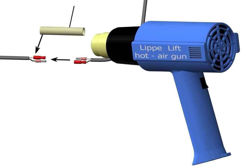
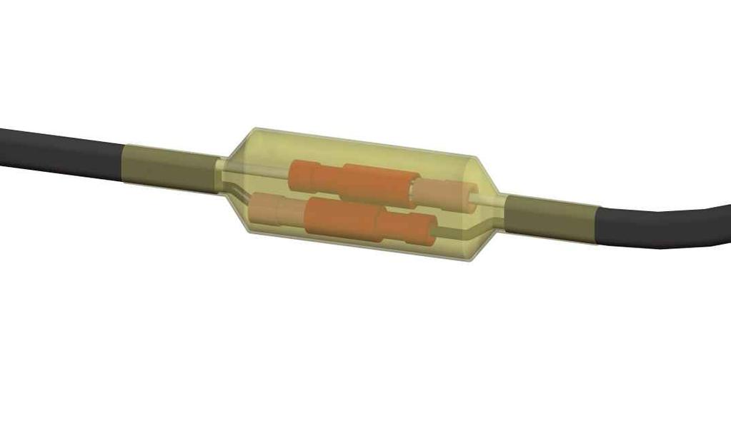
13 9.) Before driving with the lift, the track tubes must first be cleansed of any dirt. Drive the lifting unit to a position shortly before the end of the last track section and carry out any necessary adjustments. Ensure that the lifting unit does not leave the track when doing this!!! 10.) Repeat items 8 and 9 until the entire track has been installed. 11.) djust the top and, if existing, the middle stations (see item 7 (page 9)). 12.) Connect the positive and negative conductors of the battery chargers to the loading stations (use ferrules and subsequently insulate the joints with heat shrink sleeving using a hot air gun). Connect the battery charger to the house mains electricity supply. The function is subsequently to be checked (a function test is possible only if the lifting unit is in the charging station with its charging contacts). The battery charger should be mounted if possible in such a way that the user can easily see it. 13.) Connect the running rail to the building s potential equalisation cable (indoor installations: min. Cu 6 mm², outdoor installations: min. Cu 10 mm², or according to national regulations). 14.) The arrangement of the external control units must correspond to the requirements of the intended user, according to whether he/she sits, stands or is in a wheelchair. The height of the external control unit should be 800 to 1100 mm above the floor. The external control units are to be installed in such a way that the entire track can be seen from the respective control position if possible. In the case of external control units that are connected to one another, the cables are to be laid in a cable duct or a conduit. Installation instructions T80 chair lift 13 / 27 Version: /2011


14 Installation instructions T80 chair lift 14 / 27 Version: /2011


15 15.) ttach the lower tube if necessary or foreseen. It is furthermore possible to use halfen rails on the straight track sections instead of lower tubes. These are fastened with normal side mounts to the supports B Installation instructions T80 chair lift 15 / 27 Version: /2011


 Where necessary, a rear-sided cover made of Plexiglas is to be attached on the rear side of the")

16 16.) Tubes are intended to be used as anti-falling devices in curves. These tubes are to be fixed to the vertical rods using the fastening clips provided (two fastening clips per tube). The tubes should overlap the vertical rods by approx. 200 mm and be fed as far as the steps if possible. The clearance distance between the individual tubes may not exceed 120 mm. 17.) Where necessary, a rear-sided cover made of Plexiglas is to be attached on the rear side of the track between the halfen rails to prevent reaching through. The reach-through protector is clamped tight using brackets. The Plexiglas panels, which are already cut to size, are numbered sequentially on the protective film (starting from the bottom). Installation instructions T80 chair lift 16 / 27 Version: /2011
.")
 ll caps are to be attached (bolts, supports, side mounts and track tubes). 19.")


17 nother variant of the reach-through protector is to use a flexible woven screen made of fibre glass in place of the Plexiglas. This can be cut to size very easily on site with a normal pair of scissors and fastened to the vertical rods using the clamps provided (as shown below). Joints are to be placed exactly against a vertical rod and fastened there with an overlap of approx. 10mm. We recommend a max. fixing distance of 500 mm. The woven screen is supplied rolled up 18.) ll caps are to be attached (bolts, supports, side mounts and track tubes). 19.) Carry out several test runs under full load and check all safety and control functions (including the engagement of the arrester). Engage the arrester with 125 % of the max. load bearing capacity: Unhook both springs on the speed limiter (at the screw) and turn the lift in the downhill direction using the hand wheel with the brake vented until one arrester pendulum is fully engaged and the arrester switch interrupts the complete power circuit. fter that, turn the lift in the uphill direction using the hand wheel with the brake vented until the pendulum is released again and attach both springs. Labels in the respective national language are to be applied over the original labels if necessary! 20.) Give detailed instructions to the user (let him/her drive himself/herself). 21.) Touch up any paint damage (a pot of paint is supplied) and instruct the customer not to drive with the lift until the paint has dried and operation is allowed in accordance with the national regulations. 22.) Complete the installation report in detail and send it to the manufacturer s customer service department. Installation instructions T80 chair lift 17 / 27 Version: /2011
). - lign and fasten the track in accordance with the dimensions on the installation drawing (see item 5 page 5).")

18 23.) Regarding item 4 on page 4 (non-contact of the lifting unit with the floor) - Establish an auxiliary point: the lowest point of the lowest track section (see dimensional data on the installation drawing (see example below)). - lign and fasten the track in accordance with the dimensions on the installation drawing (see item 5 page 5). - Make absolutely sure that the anti-falling safety device (see below) (two brackets) is attached to the lower track tube (danger of falling!!). - Raise the lifting unit and push the roller heads onto the track tube. - If the support rollers are resting on the support rods, lift up the brake vent lever and at the same time turn the hand wheel in the DOWN direction. The respective directions of rotation are indicated directly on the hand wheel. This causes the lifting unit to move downwards (see also item 4 page 4) Insert the lifting unit from above Lastaufnahmemittel von oben einführen 300 EG fter that, continue with items 5 to 21. Installation instructions T80 chair lift 18 / 27 Version: /2011
19 Disassembly of a T80 chair lift 1.) Drive the chair lift to the lowest station. 2.) Dismount the electrical components (external control unit, battery chargers). 3.) Set the main switch to OFF. 4.) Remove the backrest (to allow access to the brake and hand wheel). 4.) Starting from the uppermost station, successively dismount the track sections in a downward direction (including the last track section before the lifting unit). ttention: It is essential to eliminate or secure any sources of danger created, such as a danger of falling (missing railing) or a danger of being cut (sharp edges), in an appropriate way! 5.) Remove the lifting unit from the running rail in an appropriate way: - If the lifting unit is standing on the floor: Loosen the last track section. Pull the brake vent lever upwards and at the same time turn the hand wheel in the DOWN direction. The last track section can then be pulled carefully out of the roller heads. - If the lifting unit is not standing on the floor: Pull the brake vent lever upwards and at the same time turn the hand wheel in the UP direction and pull the lifting unit in an upward direction out of the last running rail section. 6.) Dismantle the supports (cut through any welded supports if necessary). Pay attention to the safety instructions regarding hot work in order to avoid fires. Disposal instructions 1.) Steel scrap: steel parts of the track and supports; steel parts of the lifting unit 2.) Special waste: plastic parts, motor, cables, printed circuit boards, batteries Note: our powder coating is free of lead and cadmium Installation instructions T80 chair lift 19 / 27 Version: /2011


20 ppendix I Maximum dimensions for the installation of a T80 chair lift: d= 14mm X= max. 50mm d= 25mm X= max. 120mm Y Y Y Y= max. 1100mm Z Z= max. 350mm Installation instructions T80 chair lift 20 / 27 Version: /2011

21 ppendix II dditional wall fastening options Building fabric: horizontal coring brick, vertical coring brick, lime malm brick Drill hole diameter for connecting element: 18 mm xis spacing for connecting element: 100 mm and 110 mm Recommended dowel selection: category 5 DIN7991-M8x adhere with thread locking compound Md= 40 Nm Installation instructions T80 chair lift 21 / 27 Version: /2011

22 dditional wall fastening options Building fabric: solid brick, solid lime malm brick Drill hole diameter for connecting elements: 12 mm xis spacing for connecting elements: 100 mm and 110 mm Recommended dowel selection: category 1 DIN7991-M8x adhere with thread locking compound Md= 40 Nm Installation instructions T80 chair lift 22 / 27 Version: /2011

23 dditional wall fastening options for the following building fabrics: Building fabric: wood Drill hole diameter for connecting element: 7.5 mm xis spacing for connecting element: 75 mm Recommended dowel selection: category 6 B DIN7991-M8x adhere with thread locking compound Md=40 Nm : DIN933-M8x Md=35 Nm B: DIN Installation instructions T80 chair lift 23 / 27 Version: /2011


24 ppendix III Example: support with additional fastening point up to upper track tube Building fabrics: all Drill hole diameter for connecting elements: area : 12 mm / area B: 15.0 mm xis spacing for connecting elements: area : 190 mm / area B: 100 mm B Recommended dowel selection: see below for category rea Building fabric Concrete Other 2 Indoor area:7 / outdoor area: 1 B 3 Indoor area:7 / outdoor area: 1 Installation instructions T80 chair lift 24 / 27 Version: /2011


25 Example of a free-standing support (building fabric: concrete (C25)) Drill hole diameter for connecting elements: 20 mm xis spacing for connecting elements: 160 mm Recommended dowel selection: category 4 On foundation On steps Drill hole diameter for connecting elements: 15 mm xis spacing for connecting elements: 100 mm Recommended dowel selection: category 3 Installation instructions T80 chair lift 25 / 27 Version: /2011
26 ppendix IV The respective connecting elements are to be selected by the respective installation company. Particular attention should thereby be paid to the following parameters, among others: - Existing building fabric - Non-load-bearing layers on top of the building fabric - Edge distances - xis spacing of the connecting elements to one another - rea of use (indoor area, outdoor area, humid rooms, aggressive environmental influences (closeness to the sea, swimming pools), etc.) - Permitted area of use of the respective connecting elements Fastening forces for T80 Support with two restraints Storey ceiling or flight of stairs Post Direction of travel Normal operation [KN] Case of arrest [KN] V o V u H o H u P Fao P Fau Remarks These forces are omitted in the case of supports with footplates. Horizontal forces only in the case of arrest Installation instructions T80 chair lift 26 / 27 Version: /2011
27 Fastening forces for T80 Support with one restraint Normal operation [KN]; [KNm] Case of arrest [KN]; [KNm] V M u P Fa M Fa Remarks Only in the case of arrest Fastening forces for T80 Wall fastening Normal operation [KN] Case of arrest [KN] V o 2,1 2,95 V u 3,3 4,60 H o 2,6 3,65 H u 2,6 3,65 P Fao - 1,90 P Fau - 1,90 Remarks Horizontal forces only in the case of arrest Installation instructions T80 chair lift 27 / 27 Version: /2011
Operating Manual. for CUTTING, PERFORATING, BENDING SLB120
 Operating Manual for CUTTING, PERFORATING, BENDING SLB120 31040\B06eng 0896 0 Contents 1. Scope of delivery... 1 2. Technical specifications... 1 3. Applications... 1 4. Commissioning... 2 5. Cutting...
STORAGE & SHELVING SYSTEM - INSTALLATION GUIDE
 STORAGE & SHELVING SYSTEM - INSTALLATION GUIDE If you have ordered storage drawers, shelving, hanging rails or shoe racks this guide will help you install your storage and shelving system, together with
MAG-CONV Basic, 48, 48R & Midline Front Mount
 Parts Required: Tools Used: Mag Wheels Brakes Brake Rods Mounting Bracket Anti Tippers 7/16" Wrench Screw Driver Rubber Mallet 5/8 Wrench 5mm Allen Wrench Step Execution Figures 1 Remove front 5" total
Assembly Instructions 10 X 10 Aluminum Roof Support
 Assembly Instructions 10 X 10 Aluminum Roof Support Aluminum Roof Support Bolt Package 16-5/16 X 2 ¼ SS Bolt 24-5/16 X 1 SS Bolt 40-5/16 SS Nylon Lock Nuts 16-5/16 SS Flat Washers 28-4 ½ Wood Screws 36-1
FABA. Installation Instructions. Conductor Bar System. Publication #FABA-03 3/1/04 Part Number: Copyright 2004 Electromotive Systems
 FABA Conductor Bar System Installation Instructions Publication #FABA-03 3/1/04 Part Number: 005-1062 Copyright 2004 Electromotive Systems 1S 100 Z Installation Instructions Contents: Basic Diagram - -
Hardware and Components:
 Hardware and Components: (A) 4X 5/16 x 1 Carriage Bolt (B) 2X 5/16 x 2-1/4 Carriage Bolt (C) 2X 5/16 x 3-1/4 Hex Bolt (D) 2X 5/16 x 3/4 Hex Bolt (E) 2X 5/16 x 1-1/4 Hex Bolt (F) 5/16 x 2-1/4 Hex Bolt (G)
AUTO STABILIZING AND LEVELLING SYSTEM
 Installation Manual Make sure the caravan is parked in a safe place. Make sure the caravan brake is on. Remove all 4 corner steady legs from the caravan. Remove the corner steady legs by removing the 3
N. 15th Street, Middlesboro, KY FLIP TARP DUMP BODY INSTALLATION INSTRUCTIONS
 1-800-248-7717 1002 N. 15th Street, Middlesboro, KY 40965 FLIP TARP DUMP BODY INSTALLATION INSTRUCTIONS Congratulations on your purchase of a Mountain Flip Tarp Dump Body tarping system. With tarping systems
MM540 Installation Instructions IMPORTANT SAFETY INSTRUCTIONS - SAVE THESE INSTRUCTIONS
 MM50 Installation Instructions IMPORTANT SAFETY INSTRUCTIONS - SAVE THESE INSTRUCTIONS Please read this entire manual before you begin. Do not unpack any contents until you verify all requirements on PAGE.
Fortress Fe Posts must always be secured to the deck framing. Fortress Fe Posts should never be attached to only the deck boards.
 Installation Instructions for FortressCable V-Series Cable Stair Panel System with UB-05 With ngle dapter and Fe Posts It is the responsibility of the installer to meet all code and safety requirements,
Side Winder R o u t e r L i f t.
 Woodpeckers PRECISION WOODWORKING TOOLS Side Winder R o u t e r L i f t. INSTALLATION INSTRUCTIONS The wrench handle must be pointing left in order to fully insert or remove it. Lift Wrench Once fully
M4 Foot Operated Underpinner Instruction Manual
 M4 Foot Operated Underpinner Instruction Manual M4 Walker Rd, Bardon Hill, Coalville, Leicestershire LE67 1TU, England Tel. +44 (0)130 1692, Fax +44 (0)130 16929 e mail sales@framerscorner.co.uk M4 Underpinner
Wall mounting with holding profile
 B Main profile C Edge profile D Wall spacer E Heradesign acoustic panel Edge distance max. 250 mm c Centre distance of basic section (see table) B max. 600 mm or 625 mm a Centre distance of spacer (see
Hardware and Components:
 Hardware and Components: (A) 5/16 x 2 Hex Bolt (B) 5/16 x 2-1/4 Hex Bolt (C) 5/16 x 2-1/2 Hex Bolt (D) 4X 5/16 x 3/4 Hex Bolt (E) 4X 5/16 x 1-1/4 Hex Bolt (F) 11X 5/16 Flat Washer (G) 12X 5/16 Nylock Nut
SPIDA SAW OPERATIONS MANUAL
 SPIDA SAW OPERATIONS MANUAL CM SERIAL NUMBER. OCTOBER 2000 CONTENTS Page description 1.) Contents 2.) Safety First 3.) CM Overview 4.) CM Specifications 5.) CM Installation 6.) CM Operation Setting the
TELESCOPIC GATE MANUFACTURING AND INSTALLATION MANUAL.
 TELESCOPIC GATE MANUFACTURING AND INSTALLATION MANUAL. Telescopic gates have been manufactured for many years essentially in the same way they are largely today. In recent years hardware suppliers have
Installation instructions, accessories. TV receiver, digital
 Installation instructions, accessories Instruction No 30756561 Version 1.1 5 Part. No. 30756181, 30756569 TV receiver, digital Volvo Car Corporation TV receiver, digital- 30756561 - V1.1 Page 1 / 36 Equipment
# in 1 Metal Worker Auxiliary Operating Instructions
 340 Snyder Avenue, Berkeley Heights, NJ 07922 www.micromark.com MMTechService@micromark.com Tech Support: 908-464-1094, weekdays, 1pm to 5 pm ET #86556 3 in 1 Metal Worker Auxiliary Operating Instructions
EmagiKit. Privacy Pod Plus. Quiet. Easy. Affordable. INSTRUCTIONS ASSEMBLY
 EmagiKit Privacy Pod Plus Quiet. Easy. Affordable. INSTRUCTIONS ASSEMBLY DIMENSIONS AND COMPONENTS 47 47 Ceiling Unit 2-B 2-L 2-R Glass Door Corner Trim Door Handle 90 Adjustable Height Work Surface 1-B
Installation Instructions
 For Medium (15-18.5K) + Heavy duty (22-28.5K) Air Conditioner READ BEFORE INSTALLING UNIT To avoid risk of personal injury, property damage, or product damage due to the weight of this device and sharp
Door window. Front door window, assembly overview
 64-50 Door window Front door window, assembly overview 1 - Window channel Pushed onto flange 2 - Door window Removing Page 64-52 Adjusting Page 64-53 3 - Door 4 - Outer window channel Pushed onto flange
Operating, Servicing, and Safety Manual Model " Foot Shear CAUTION: Read and Understand
 Operating, Servicing, and Safety Manual Model 3000 52" Foot Shear CAUTION: Read and Understand These Operating, Servicing, and Safety Instructions, Before Using This Machine. SAFETY The purpose of the
Sliding Door Kit
 YOU MUST READ THIS DOCUMENT BEFORE YOU BEGIN TO ASSEMBLE THE DOOR KIT. Thank you for purchasing this GrowSpan door kit. When properly assembled and maintained, this product will provide years of reliable
MM340 Installation Instructions IMPORTANT SAFETY INSTRUCTIONS - SAVE THESE INSTRUCTIONS
 MM30 Installation Instructions IMPORTANT SAFETY INSTRUCTIONS - SAVE THESE INSTRUCTIONS Please read this entire manual before you begin. Do not unpack any contents until you verify all requirements on PAGE.
Privacy Wall Glass Selections - Polished Edge Slider Door
 Privacy Wall Glass Selections - Polished Edge Slider Door 3/6" HEX BIT PUTTY KNIFE #2 ACR BIT SUCTION CUP HOLDERS DOOR LEAF: Satin Tempered Clear Tempered LOCTITE 425 SIDE LIGHT ETCHED GLASS STYLES: Satin
1 of 2 3/3/2017 4:49 PM
 1 of 2 3/3/2017 4:49 PM Front Door Window, Assembly Overview 1 - Window guide - Inserted on flange 2 - Door 3 - Inner window recess seal - Inserted on flange 4 - Bolt - 20 Nm 5 - Carrier assembly - Window
Taurean Sectional Garage Door INSTALLATION INSTRUCTIONS
 BEFORE YOU BEGIN MAKE SURE THESE INSTRUCTIONS ARE READ AND UNDERSTOOD COMPLETELY. THESE INSTRUCTIONS ARE INTENDED FOR PROFESSIONAL GARAGE DOOR INSTALLERS. ALL REFERENCES ARE TAKEN FROM THE INSIDE LOOKING
Tree protection systems 2.0
 r e z t ü h c s m u Die Ba Tree protection systems 2.0 Installation and assembly instructions 2 General information The installation instructions below are merely a recommendation for how to install the
PORCH-LOC INSTALLATION INSTRUCTIONS
 PORCH-LOC INSTALLATION INSTRUCTIONS 2017 HB&G Building Products, Inc. Porch-Loc Installation Instructions NOTE: DISCARD THE INSTALLATION INSTRUCTIONS AND HARDWARE THAT CAME IN YOUR PERMAPOST PACKAGING
INSTALLATION MANUAL GIOTTO SCREEN
 INSTALLATION MANUAL GIOTTO SCREEN Before installing the Giotto screen, please read the following instructions carefully: The Giotto screen must be used INDOORS ONLY. It is forbidden to stay under the Giotto
3.2.3 Rear Door Window and Quarter Window Carrier Assembly
 Tighten all bolts. Tighten bolts marked -1- and -2- in specified sequence. Tightening torque: 8 Nm Remaining bolts can be tightened in any sequence. Insert door window -3- through window recess without
Curium 19H Installation Instructions & Parts List
 Curium 19H Installation Instructions & Parts List Illustration Curium 19H Right Hand Page 1 of 15 01/07/2016 Revision 2.1 IMPORTANT This shower screen / enclosure must be installed by suitably qualified
YOUR LIFE. YOUR FIRE. Ortal Curved & Islands Fireplaces User s Manual
 YOUR LIFE. YOUR FIRE. Ortal Curved & Islands Fireplaces User s Manual [USA Fireplace Models [THIS ISTALLATION MANUAL INCLUDES ASSEMBLY INSTRUCTIONS FOR THESE MODELS: STAND ALONE 7565 CURVED TUNNEL DOUBLE
3 BRACKET TO GUIDE ATTACHMENT. RIGHT END Figure 1. EXTENDED BRACKET (for doors taller than 8-8 ) SERIES 650. RIGHT END COTTER PIN Figure 6
 SERIES 650. RIGHT END COTTER PIN Figure 6") 2 DOOR ARRANGEMENT. A Lay door on a clean floor inside of building and in front of opening (see Figure 1). NOTE: Door can be damaged if laid on unclean surface. B Distribute parts bags, guides, stops and
2 DOOR ARRANGEMENT. A Lay door on a clean floor inside of building and in front of opening (see Figure 1). NOTE: Door can be damaged if laid on unclean surface. B Distribute parts bags, guides, stops and
Front axle components, overview
 j a t Front axle components, overview 40-1 General Information Load bearing components and parts of the suspension must not be welded or straightened. Vehicles without drive axle must not be moved, or
BY ALIEN TECHNOLOGIES CORP
 BY ALIEN TECHNOLOGIES CORP Assembly Instructions TopLift Pros YOU MAY ALSO REVIEW OUR ASSEMBLY VIDEO, PLAY AND PAUSE AT YOUR CONVENIENCE. JUST VISIT US AT WWW.TOPLIFTPROS.COM AND GO TO Customer Support
ClearSpan PolyMax Windbreak Wall
 ClearSpan PolyMax Windbreak Wall Photo may show a different but similar model. 2007 ClearSpan All Rights Reserved. Reproduction is prohibited without permission. Revision date: February 2007ldg STK# DIMENSIONS
Mounting a BalanceBox 400 to a brick wall
 Unpack the BalanceBox 400 and remove the Wall frame cover and its bag of screws. Slide the cover out at the top. NOTE: the cover is NOT included with the BalanceBox 400H LOCK SCREW HOLE MOBILE STAND MOUNTING
Assembly instructions
 Commission: Order no.: Rondo Pavilion PR Ø3.9 Technical changes reserved Assembly instructions As at: 05.011 Sliding door Dear Garden lover, we congratulate you on the purchase of a quality product from
ASSEMBLY INSTRUCTIONS FOR SL500A AND SL500AL
 ASSEMBLY INSTRUCTIONS FOR SL500A AND SL500AL January 2013 The SL500A is a square upright glass cabinet with a single hinged lockable door. It has five adjustable shelves plus the base. It also has an optional
Ceiling mounting application, U support and bracket. Standard mounting of a cable tray with support, type US.., and suitable support bracket, type AW.
 Cable tray system RKS-Magic 35 and 60 mm Cable trays Type RKS-Magic Side height: 35, 60 mm Surface: FS Fittings: According to side heights Connecting parts According to side heights VDE testing According
Installation Instructions
 edium + Heavy duty READ BEFORE INSTALLING UNIT Preliminary instructions: 1. Check window opening size: the mounting parts furnished with this air conditioner are made to install in a wooden sill double-hung
READ BEFORE INSTALLING UNIT INSTALLATION WARNINGS AND CAUTION
 edium + Heavy duty READ BEFORE INSTALLING UNIT INSTALLATION WARNINGS AND CAUTION Carefully read the installation manual before beginning. Pay attention to danger and safety notices. be exposed: Carefully
Installation Guide. Bi-fold Doors
 Installation Guide Bi-fold Doors Installation Guide Components box 1. 6. 2. 3. 7. 5. 4. 8. Contents 1. Fixing plugs 2. Wedge gasket 3. Bottom trolley 4. Top trolley 5. Magnetic keep (x 2 if door height
Section 1 Cubicles. Section 2 IPS Duct Panel Systems. Section 3 - Vanity Units Components & Assembly 12. Section 4 Basic Maintenance.
 Contents Section 1 Cubicles Cubicle Components 3 Cubicle Installation 4-5 Cubicle Fittings Brackets 6 Hinges 7 Partition Support Leg 8 Indicator Bolt 9 Section 2 IPS Duct Panel Systems Frame, Flash & Panel
VARIABLE SPEED WOOD LATHE
 MODEL MC1100B VARIABLE SPEED WOOD LATHE INSTRUCTION MANUAL Please read and fully understand the instructions in this manual before operation. Keep this manual safe for future reference. Version: 2015.02.02
INSTALLATION INSTRUCTIONS
 PART NO. 911000T 911000PS 915000T 915000PS PRODUCT DESCRIPTION: Sport Bar 2.0, Full size Textured Black Sport Bar 2.0, Full size Polished Stainless Steel Tubes Sport Bar 2.0, Mid size Textured Black PRODUCT
YOUR LIFE. YOUR FIRE. Ortal Curved & Islands Fireplaces Installation Manual. Ortal USA - Version: 1.3 November, 2017 SKU: KPMANCIRISLUS17B
 YOUR LIFE. YOUR FIRE. Ortal Curved & Islands Fireplaces Installation Manual Ortal USA - Version: 1.3 November, 2017 SKU: KPMANCIRISLUS17B [THIS ISTALLATION MANUAL INCLUDES ASSEMBLY INSTRUCTIONS FOR THESE
Folding-Arm Cassette Awning markilux 6000
 Folding-Arm Cassette Awning markilux 6000 Fitting Instructions 1. Fitting the mounting fixtures 1.1 Fitting height H = Projection Y = Horizontal cover X = Value from Table 2 K = Headroom = G X G = Fitting
FLIP TARP SINGLE & DOUBLE UNDERBODY TRAILERS
 1-800-248-7717 1002 N. 15th Street, Middlesboro, KY 40965 FLIP TARP SINGLE & DOUBLE UNDERBODY TRAILERS INSTALLATION INSTRUCTIONS Congratulations on your purchase of a Mountain Flip Tarp Trailer system.
assembly instructions
 door opens outwards door opens inwards front cubicle door opens outwards or inwards with side panel seite 1 ensure that the supplied parts are complete by checking the packing list. make sure that tools
V Installation instructions, accessories. Auxiliary seat. Volvo Car Corporation Gothenburg, Sweden V70 (00-08) 2002
 2002") Installation instructions, accessories Instruction No 8624018 Version 1.3 Part. No. 30749269, 30749270, 30749271, 30749272, 30749273, 30749274 Auxiliary seat M8901699 Volvo Car Corporation Auxiliary seat-
Installation instructions, accessories Instruction No 8624018 Version 1.3 Part. No. 30749269, 30749270, 30749271, 30749272, 30749273, 30749274 Auxiliary seat M8901699 Volvo Car Corporation Auxiliary seat-
Gared Pro-S Portable Backstop
 Models: 9616 & 9618 Installation, Operation and Maintenance Instructions Please read all instructions before attempting installation or operation of these units SAVE THESE INSTRUCTIONS FOR FUTURE USE PUBLICATION
Hydraulic Clamp Carrier. Installation & Operation Manual
 Hydraulic Clamp Carrier Installation & Operation Manual Hydraulic Clamp Carrier Installation & Operation Manual Quick Machinery Company 8272 Peninsula Drive Kelseyville, CA 95451 phone: (707) 272-6719
Instruction Sheet RADIO FREQUENCY SYSTEMS. Install. Instr. for Microwave Parabolic Antennas 2.4 m (8 ft) No Rev.
 No Rev.") Instruction Sheet No. 412764 Rev. B ECO 12469 Install. Instr. for Microwave Parabolic Antennas 2.4 m (8 ft) These Installation Instructions are valid for antennas in the following version: reflector 2.4
Instruction Sheet No. 412764 Rev. B ECO 12469 Install. Instr. for Microwave Parabolic Antennas 2.4 m (8 ft) These Installation Instructions are valid for antennas in the following version: reflector 2.4
Puerto Rico - 2 Door Shoes Cupboard
 Puerto Rico - oor Shoes Cupboard ssembly Instructions - Please keep for future reference 04/478 imensions Width - 86cm epth - 38.5cm Height - 108cm Important Please read these instructions fully before
INSTALLATION INSTRUCTIONS FOR HAND OPERATED MODELS: 170, 171-R, 171-N, 172, 260
 INSTALLATION INSTRUCTIONS FOR HAND OPERATED MODELS: 170, 171-R, 171-N, 172, 260 I. SUSPENDED INSTALLATIONS NOTE: MODEL 260 FENSTEEL TRACK IS ASSEMBLED IN THE SAME MANNER AS DESCRIBED BELOW WITH THE EXCEPTION
Instruction Manual. Manual Furniture Mover. Note: Owner/Operator must read and understand this instruction manual before using the furniture mover.
 Instruction Manual Manual Furniture Mover Note: Owner/Operator must read and understand this instruction manual before using the furniture mover. I - Contents 1. Application 2 Specifications 3.Assembly
Model 2400/4000 Illustrated Installation Instructions
 Model 2400/4000 Illustrated Installation Instructions Contractors Wardrobe DESIGNERS MNUFCTURERS 26121 venue Hall Valencia, C 955 (661) 257-77 Fax: (661) 257-4907 Toll Free: (800) CW-DOORS (800) 293-6677
TABLE OF CONTENTS REQUIRED TOOLS
 TABLE OF CONTENTS SECTION SECTION TITLE PAGE NO. 1 2 3 4 5 Assembling Mounting Structure Installing Bicycle Supports Mounting Rack to Wall Adding Sections Customizing Rack Configuration REQUIRED TOOLS
Installation Instructions
 CHEVY / GMC 20K Industry Standard Rail Custom Mounting Kit #2724 Gross Trailer Weight (Maximum)...20,000 lbs. Vertical Load Weight (Max. Pin Weight)...5,000 lbs. SYSTEM TOW CAPACITY Please note, in order
Operating Instructions
 Operating Instructions Holding the material against the angle gauge slide it into the forming head. Be sure that the material remains against the gauge until work is finished. NOTE: This machine will handle
C4 Fabrication Rock Slider Installation 14+ 5th Gen 4Runner w/o KDSS
 C4 Fabrication Rock Slider Installation 14+ 5th Gen 4Runner w/o KDSS Thank you for your purchase of the C4 Fabrication s 5th Gen 4Runner Rock Sliders! This product was carefully crafted to ensure a perfect
S48-L12-SC AND G48-L12-GC STEEL PORTA-DOCK S82 SC 6 X 12 PLATFORM AND G82 GC 6 X 12 PLATFORM
 PAGE 1 OF 6 PORTA-DOCK, INC. S48-L12-SC AND G48-L12-GC STEEL PORTA-DOCK S82 SC 6 X 12 PLATFORM AND G82 GC 6 X 12 PLATFORM Thank you for purchasing our product! *Please read these instructions and follow
EBTRON a measurable difference!
 GP1, HP1 AND SP1 DUCT AND PLENUM PROBE INSERTION MOUNT INSTALLATION Document Number 930-0030 OVERVIEW This document provides the instructions necessary to install Standard insertion mount probes as shown
MODEL 83 Pail Handler
 MORSE MFG. CO., INC. 727 West Manlius Street P.O. Box 518 East Syracuse, NY 13057-0518 Phone: 315-437-8475 Fax: 315-437-1029 Email: service@morsemfgco.com Website: www.morsemfgco.com COPYRIGHT 2005 MORSE
Quill Stop V2 Installation Guide 11/16/2014
 Thank you for purchasing the Quill Stop for the Sieg X3 (Grizzly G0463) and SX3 (Grizzly G0619) mills. Your feedback is always appreciated. Please email questions and comments to gregpriest@cox.net. What
ROLL-A-GLIDE INSULATED ROLLER DOOR
 ROLL-A-GLIDE INSULATED ROLLER DOOR Installation Instructions 1. Motor 13. Brush / Wear Strips 2. Axle Assembly 14. Curtain Assembly 3. Rigid Link Collars 15. Door Laths 4. Octagonal Plug End 16. Locking
WPS crew Doors Installation instructions
 WPS-132-133 crew Doors Installation instructions ORDER OF INSTALLATION FOR A COMPLETE ENCLOSURE OF A CREW WPS (Weather Protection System) IS AS FOLLOWS: 1. Heater 2. Rear Thresholds - Right Hand & Left
400A 40113V, 401A 40120V, & 401AL 40120VL ALUMINUM VERTICAL 4000 LB LIFT INCLUDES SCREW LEG ASSEMBLY INSTRUCTIONS
 12/11/07 PAGE 1 OF 12 400A 40113V, 401A 40120V, & 401AL 40120VL ALUMINUM VERTICAL 4000 LB LIFT INCLUDES SCREW LEG ASSEMBLY INSTRUCTIONS Thank you for purchasing our product! *Please read these instructions
Curium 19.4H Installation Instructions & Parts List
 Curium 19.4H Installation Instructions & Parts List Illustration Curium 19.4H Right Hand Page 1 of 21 30/06/2016 Revision 1.0 IMPORTANT This shower screen / enclosure must be installed by suitably qualified
Code Product Qty 1 Top Vertex 3 2 Hot End Housing 1 3 Bottom Vertex 3 4 Print Platform Lock 3 5 End Stop Holder 3 6 Filament Feeder Motor Bracket 1 7
 List of Parts Code Product Qty 1 680mm Extrusion 3 2 Power Supply 1 3 240mm Extrusion 9 4 42mm Nema 17 Stepper Motor 3 5 Slider-Hotend Connecting Rod 6 6 48mm Nema 17 Stepper Motor 1 7 Linear Rail with
Installation Instructions for Vista Air Vertically Folding Walls
 Installation Instructions for Vista Air Vertically Folding Walls Use these instructions in conjunction with your shop drawings to see the specifics that are particular to the model you are installing.
GMR 1 PROFESSIONAL. ÁU~²Ýœ ÈULM¼« Àπ ß Õ ŸË Õ Èß π Petunjuk-Petunjuk untuk Penggunaan HıÎng dõn s dùng Instructions d emploi. Operating Instructions
 609 40 44 - Buch Seite Dienstag,. Juni 004 :5 5 GMR PROFESSIONAL * Des idées en action. Operating Instructions Àπ ß Õ ŸË Õ Èß π Petunjuk-Petunjuk untuk Penggunaan HıÎng dõn s dùng Instructions d emploi
SERVICE MANUAL FOR HOMELOCK M1034D 2034D 1134DW 1134D
 SERVICE MANUAL FOR HOMELOCK M1034D 2034D 1134DW 1134D 11.2000 2.2012 I HOW TO USE THIS MANUAL... 1 II HOW TO ADJUST... 2 1. Height of needle bar... 2 2. Position of the lowerlooper... 3 3. Timing of the
INSTRUCTIONS FOR INSTALLATION AND SERVICE OF ZF3000 EXTERNAL BLIND
 R INSTRUCTIONS FOR INSTALLATION AND SERVICE OF ZF3000 EXTERNAL BLIND Before starting installation of the external blind, please read the following instructions. During transportation and storage, the
ED1300/1300F SERIES CONCEALED VERTICAL ROD DEVICE INSTALLATION INSTRUCTIONS
 ED1300/1300F SERIES CONCEALED VERTICAL ROD DEVICE INSTALLATION INSTRUCTIONS Ver.2 1300 SERIES CONCEALED VERTICAL ROD DEVICE Top Strike Latch Screws Strike Screws Release Plunger Top Latch Plunger Screws
SAM. Model: STV-C65 LCD Mobile Visualized Stand Instruction Manual. Weight Capacity: 1251bs / 56.7kg Suits LCD Flat Panel Display: 42"-55" Page 20
 SAM Model: STV-C65 LCD Mobile Visualized Stand Instruction Manual Weight Capacity: 1251bs / 56.7kg Suits LCD Flat Panel Display: 42"-55" 20 Step 6 LCD Mobile Lift Stand Model: STV-C65 Cable management
Vanity Installation Instructions
 Vanity Installation Instructions Segments of these instructions will relate to your vanity. Please read these instructions thoroughly and ensure the appropriate instructions are used during the installation
Version: 1.0 Revised: 6/8/2011. CBU Assembly Instructions Manual
 CBU Assembly Instructions Manual Contents 1 General... 3 2 Package... 4 2.1 Packing order... 4 2.2 Unpacking... 5 3 Assembly of the body... 6 3.1 General... 6 3.2 Mounting base drilling chart... 8 3.3
CHICKEN COOP & CHICKEN RUN. Tools required for assembly (not included)
") CHICKEN COOP & CHICKEN RUN ASSEMBLY MANUAL SKU# 6839 Tools required for assembly (not included) Distributed by: TRACTOR SUPPLY COMPANY 0 VIRGINIA WAY, BRENTWOOD, TN 3707 For customer support, call: -888-376-960
CHICKEN COOP & CHICKEN RUN ASSEMBLY MANUAL SKU# 6839 Tools required for assembly (not included) Distributed by: TRACTOR SUPPLY COMPANY 0 VIRGINIA WAY, BRENTWOOD, TN 3707 For customer support, call: -888-376-960
Rollerscreen ENG. Installation Instructions
 Rollerscreen Instructions Introduction Figure 1, System Overview and Individual Components -2- Introduction INTRODUCTION Parts List REFERANCE QTY PRODUCT DESCRIPTION A1 2 Top and Bottom Tubes B1 1 Screen
Universal flat-panel mount
 I N S T A L L A T I O N M A N U A L Universal flat-panel mount www.christiedigital.com PM 2004/ REV 02 Contents - Assembly drawing - Fine tune tilt adjustments - Parts list - Installing the adapter plate
Installation Instructions for. Handrail Component System
 Handrail STEP-BY-STEP Installation Instructions for Handrail Component System Rise in Inches Run in Inches 8 8.5 9 9.5 10 10.5 11 11.5 12 12.5 13 13.5 14 14.5 15 8.5 47 45 43 42 40 39 38 36 35 34 33 32
Owner s Manual #TSGUARD
 Owner s Manual #TSGUARD PSI Table Saw Dust Collection Guard The ideal solution for table saw dust control. Version 3, 02/04 2004 PSI Woodworking Products 9900 Global Rd., Philadelphia, PA 19115 WARRANTY
INSTALLATION INSTRUCTIONS VENETIAN 84" SLIDING SHOWER DOOR SYSTEM (180º INSTALLATION)
") INSTALLATION INSTRUCTIONS VENETIAN 84" SLIDING SHOWER DO SYSTEM (180º INSTALLATION) 28539 Industry Drive, Valencia, CA 91355 Toll Free Phone: (877) 728-3874 Toll Free Fax: (888) 440-9567 Phone: (661) 775-1675
INSTALLATION INSTRUCTIONS VENETIAN 84" SLIDING SHOWER DO SYSTEM (180º INSTALLATION) 28539 Industry Drive, Valencia, CA 91355 Toll Free Phone: (877) 728-3874 Toll Free Fax: (888) 440-9567 Phone: (661) 775-1675
Installation for Full Size Polaris Ranger Crew Doors
 Installation for Full Size Polaris Ranger Crew Doors Order of Installation: Heater Doors Wiper on to Windshield Windshield Top & Back Panel Note: Most of the steps in these instructions need to be repeated
IMPORTANT: PLEASE RETAIN THIS INSTRUCTION MANUAL FOR FUTURE REFERENCE
 IMPORTANT: PLEASE RETAIN THIS INSTRUCTION MANUAL FOR FUTURE REFERENCE 005-07 Cadillac STS Classic 3D Z, Classic Dual Weave, Classic Mesh & Classic Black Mesh Grilles B 7 HR 3 STS Classic 3D Z Grille Part
SLIDING DOOR for CORNER installation ONLY - this door closes to side panel -
 by KUDOS INSTALLATION INSTRUCTIONS SLIDING DOOR for CORNER installation ONLY - this door closes to side panel - Please read these instructions throughout before installing as incorrect fitting will invalidate
S E L E C T I O N. Arm Curl. User manual
 S E L E C T I O N T H E S T R E N G T H E V O L U T I O N User manual The identification plate of the and manufacturer, affixed behind the seat, gives the following details: A Name and address of the manufacturer
February 2004 RONDA. Circular Formwork Instructions for assembly and use
 February 2004 Circular Formwork Instructions for assembly and use Table of Contents Product Features 2 General Survey 3 Components 4 7 Measures of Ronda Elements 8 9 Adustment of Radii 10 11 Connections
Installation Instructions
 READ BEFORE INSTALLING UNIT For Slider Casement Air Conditioners To avoid risk of personal injury, property damage, or product damage due to the weight of this device and sharp edges that may be exposed:
Deauville Installation Guide
 vjul16 (for 17 or 24 mm Surface Wall Profiles) DO NOT ASSEMBLE WITHOUT FULLY READING THESE INSTRUCTIONS Page 2 Thank you for purchasing this Deauville shower enclosure. Please study these instructions
Technical description
 STAHLWILLE Standard Manoskop 721 Service Manoskop 730 List of contents Technical description... 27 ã=important safety points... 30 Operation... 32 Maintenance... 42 Cleaning the Manoskop... 47 Accessories...
ESA-300 Full Breakout
 Interior View 0 Installation Instructions For use with ESA II Controler DORMA AUTOMATICS, Inc. 94 Sherwood Drive Toll-Free: 877-67-6 DL844-00 Lake Bluff, IL 60044 Fax: 877-4-7999 Rev. /07 Tools Required:
WSG 8-115; 8-125; P; WSG ; WSG P; WSG PS; WSG P; WSG 15-70Inox
 Repair instructions Page of 47 Contents. Models described 2. Technical data 3. Notes and requirements 4. Tools required 5. Lubricants and auxiliary substances required 6. Disassembly 7. Assembly 8. Connection
Sunrise Deck Assembly Instructions for Kingston Left
 Sunrise Deck Assembly Instructions for Kingston Left It s easiest to build the deck frame first like it will be lying on its back and then after all 4 legs and horizontals are in place, tip the deck toward
Installation and Assembly: Projector Ceiling/Wall Mount
 Installation and ssembly: Projector Ceiling/Wall Mount Models:PRG-EX, PRG-EX-S, PRG-EX-W PRG-EXB, PRG-EXB-S, PRG-EXB-W PRG-EXC, PRG-EXC-S, PRG-EXC-W R This product is intended for use with UL Listed products
Ford Pick Up Rear leaf Spring Kit Installation Instructions
 1948-1956 Ford Pick Up Rear leaf Spring Kit Installation Instructions 1-800-984-6259 www.totalcostinvolved.com Parts 48 inch leaf (2) springs (4) U-bolts 3/8-24 x l 1/4bolts (16) & nuts (2) 1/2-20 x 4
Malibu - 3 Drawer 2 Door Robe
 Malibu - 3 Drawer Door Robe ssembly Instructions - Please keep for future reference 7/83 38/3574 58/904 37/187 58/7679 79/1496 6/617 58/803 57/51 79/1960 55/7788 47/766 66/7355 49/661 78/5189 78/0830 Dimensions