Assembly Instructions 30x30x15 Round Style Portable Building. ASSEMBLY INSTRUCTIONS ROUND STYLE 30x30x15
|
|
|
- Egbert Holland
- 5 years ago
- Views:
Transcription
1 ASSEMBLY INSTRUCTIONS ROUND STYLE 30x30x15 Please read instructions completely before you begin. This will help attain the best results for your installation. CONGRATULATIONS! Congratulations on your purchase of a Rhino Shelter 30x30x15 Round Style Portable Building. With proper installation, use and maintenance, your new unit will provide many years of good and suitable service. Your new Rhino Shelter portable enclosure is a combination of excellent engineering and well thought out design. The unit is comprised of a rigid tubular frame, covered with a long life polyethylene cover and double door ends. The multiple part frame assembly is pre-drilled for easy insertion of frame bolts. The tubing is made from highgrade galvanized steel., resisting moisture and oxidation over the life of the shelter. The cover and doors are made from ASTM-5 approved polyethylene materials. The cover is UV protected for exposure to sunlight. SAFETY WARNING The installation of this unit must conform to the requirements of all authorities having jurisdiction in your specific local area. In the absence of such requirements, the assembly and installation must conform to the provided assembly and installation instructions. Rhino Shelter will not responsible for failure to comply with any requirements in a given local area. Damages, consequential damages, or injuries caused by improper installation, alteration, improper use, or damages caused by snow, wind, or any acts of nature are strictly that of the user. Unit is not intended for occupancy for any length of time. NO running of internal combustion engines, open flames or contact with heated surfaces is allowed. For installation assistance or Customer Service, please call or , 8AM-5PM EST. Cartons should be inspected upon delivery from carrier, and any evident damages should be noted on the bill of lading before signing. If upon opening the cartons hidden damage is discovered, contact carrier or it s agent immediately. Claims for shipping damage MUST be made with the shipping company. An inspection of the goods will most likely be required. Do not discard packing or any components before the freight company inspection. All claims for freight damage must be made within 15 days of receipt of the goods in accordance with ICC regulations. ASSEMBLY PROCEDURE The proper sequence and steps to install this unit will produce a proper and good installation. Failure to read and follow these guidelines may result in an improper installation and will void all warranty and protection the owner is entitled to with the product. The steps to be undertaken are: 1. Perform an inventory check before beginning, to be certain all components are available for installation. 2. Prepare location and place all unit boxes near location sight. 3. Assemble Seven (7) Arch Assemblies of unit. 4. Assemble unit End Arch, first Interior Arch, and Wind Braces with the first ridge crest, base, and side rail sections. 5. Add additional Arch Assemblies with each section of base rails and side rails. 6. Level and square Frame of Unit. 7. Anchor frame assembly to ground with provided anchors, U-bolts and drive rod. 8. Install Doors (2) on ends of frame assembly. 9. Install Main Cover over frame assembly. 10. Install Door Roll-up kits TOOLS REQUIRED The following hand tools will be needed for proper installation of your new Rhino Shelter building: 9/16 Open End Wrench 9/16 Socket or Box Wrench Large Flat Head Screwdriver 2lb maul or Sledgehammer 2 Foot Level 12 Step Ladder Stakes & String for squaring Frame INVENTORY CHECK Start installation procedure by removing all components from packaging to ensure all components are present. Inventory chart appears on the last page of this manual. 1
2 2
3 #1 #1 #1 #1 3
4 4
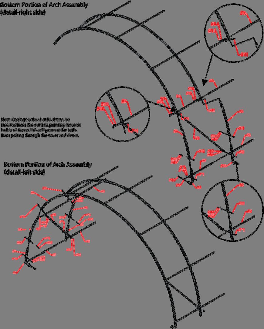
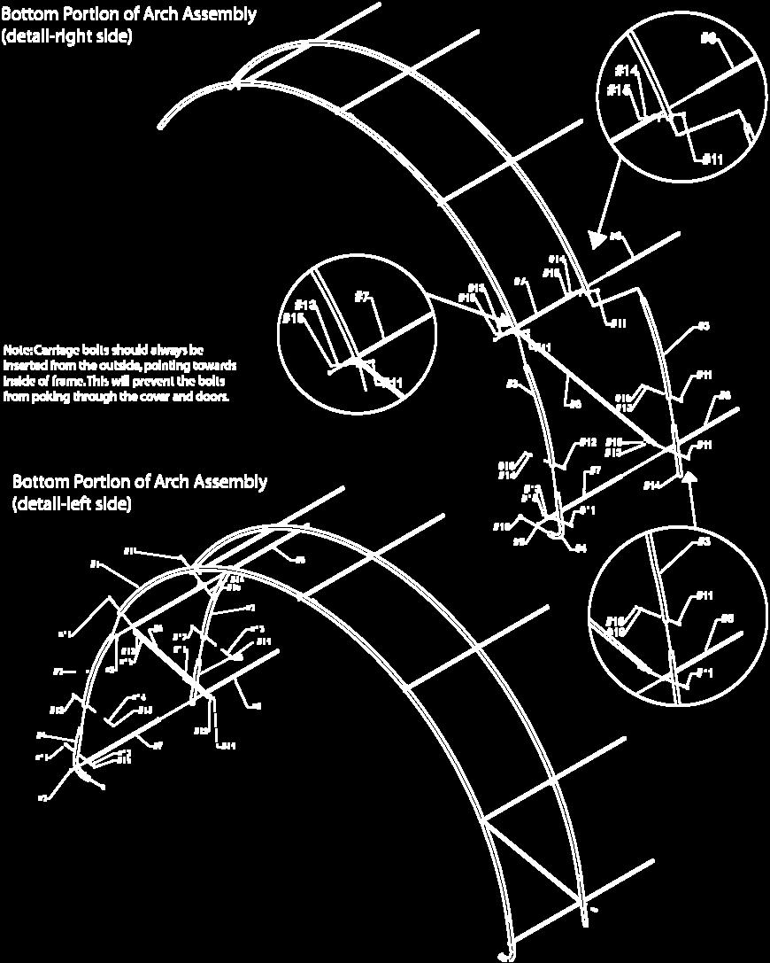
5 SITE PREPARATION Select a level or as close to level as practical location for your Rhino Shelter Building. The building should be placed on a base of materials suitable for the storage load to be protected. The unit should not be located under trees, which will shed hard fruit such as apples, walnuts, or heavy pine cones. The cover of your unit will protect against normal falling leaves and light debris, however, large branches or other falling items may cause a puncture or tear in the cover material. Take notice of drainage around your intended location. Water draining from the surrounding terrain should be planned so that it does not run into the unit. As well, rain or melting snow hat comes off the unit should be drained away rather than accumulate and pool around the unit. Check to be certain that adequate clearance is allowed for entry and exit from ends of the unit. As unit has doors on both ends, ideally boat or equipment can be inserted or removed from either end. Using the stakes and string, measure off and square area for intended installation. Level the ground as best as possible. A properly leveled frame yields maximum strength. ARCH AND FRAME ASSEMBLY STEP 1. ASSEMBLE THE FRONT & REAR END ARCHES AND #4 MIDDLE ARCH W/FEET (3 ARCHES) Each ARCH consists of: 3 - #1 CT-7006 Crest Tube-swedged end 1 - #2 CT-7007 Crest Tube-plain ends 2 - #3 CT-7008 Arch Side Tube 2 - #4 EUL-7002 Arch End Upright with Foot Use Carriage Bolts with Washers and Nuts through pre-drilled holes in frame members. (refer to detail of arch assembly for correct hardware) Be certain to insert carriage bolts from the outside into the interior of the unit, with the washers and nuts on the inside of the frame. This will prevent the bolts from puncturing through the cover material. Do not tighten down the nuts completely until frame is fully assembled and set in place. STEP 2. ATTACH CORNER WIND BRACES TO FRONT AND REAR END ARCHES Attach Corner Wind Braces #6 CW-7005 to the INSIDE of EACH side of the End Arches you assembled in step 1. Refer to detail drawing for correct hardware. Do not tighten completely. STEP 3. ASSEMBLE THE REMAINING (4) FOUR INTERIOR ARCHES Each INTERIOR ARCH consists of: 3 - #1 CT-7006 Crest Tube-swedged end 1 - #2 CT-7007 Crest Tube-plain ends 2 - #3 CT-7008 Arch Side Tube 2 - #5 EUL-7003 Arch End Upright plain base Use Carriage Bolts with Washers and Nuts through predrilled holes in frame members. Refer to detail drawing for correct hardware. Be certain to insert carriage bolts from the outside into the interior of the unit, with the washers and nuts on the inside of the frame. Do not tighten down the nuts completely. 5


 with feet is put on in the middle of the frame support. Stand an Interior Arch Assembly (without feet) assembly into place about 60 from end arch assembly.")
6 STEP 4. START COMBINING ARCH SECTIONS TO BUILD FRAME Stand first End Arch Assembly up and support with the wind brace temporarily. Attach #7 ECR-7003 Plain End Cross Rails to the inside of the End Arch Assembly STEP 5. TOP RIDGE CREST CROSS RAIL Begin the Top Ridge Crest Cross Rail by placing the first end UNDER the End Arch Assembly, secure loosely with carriage Bolt CBN , with washer and nut facing interior of unit. Under End Arch using 4 Carriage bolts, washers and nuts through the pre-drilled holes. Again do not tighten down completely. Always remember to insert bolts from the outside into the interior to prevent damage to cover. Over Interior Arch STEP 6. CONNECT ADDITIONAL ARCHES Add Interior Arch Assembly #3 to the first two arches assembled in Step 4. The Top Ridge Crest Cross Rail (only) will be UNDER the End Arches and OVER the Interior Arches (see Illustration). All the other Cross Rails will be on the inside of the frame. Interior Arch Assembly #4 (Middle Arch) with feet is put on in the middle of the frame support. Stand an Interior Arch Assembly (without feet) assembly into place about 60 from end arch assembly. Align holes in Arch with Cross Rails. Using 4 Carriage Bolts, with nuts and washers connect the Side Cross Rails between the arches. Connect Wind Brace from End Arch Assembly To first Interior Arch. This will make the first two arches self-supporting. Insert next Cross Rail into the base and Side Rails for the next arch assembly. Interior Arch Assembly #5 and #6 have plain feet ends. The last Arch #7 will be the remaining End Arch Assembly with feet. Make certain to install the Wind Braces between the End Arch Assembly (#7) and the 6


7 first Interior Arch Assembly (#6) to complete the frame assembly. DO NOT completely tighten down bolts that connect the Cross Rails to the END ARCHES, they must be removed for End Panel Zippered Door Installation. String drawn along base of frame STEP 7. LEVEL AND SQUARE FRAME Align the first side of the building arch assemblies using a string. This should be the permanent position desired for the building. Align each Arch with string to make edge of Frame STRAIGHT before securing Measure the base span of each arch, side to side. The outside of the arch bases should be 30. Too wide a span will weaken the frame resistance to load, such as snow, and prevent the doors and main cover from fitting properly. Adjust each arch to the correct width, using the first side aligned above. Measure diagonally from inside corner to inside corner of frame. Both diagonal measurements should match. Adjust frame and support as necessary to bring frame into square. Failure to square frame will result in poor cover fit and reduced strength and rigidity. Frame should be 30 side to side and 30 front to back Outside Dimensions. 7


8 30 Length and 30 Width Outside Dimensions MAINTAINING FRAME POSITION To help hold the frame in place and square, insert a piece of rebar or landscape stake into the hole in the end and center arch feet into the ground. This will help keep the frame square, and prevent the ends from spreading and straining the zippered doors. PROPER BASE SUPPORT The weight of the building will rest on the base of the arch uprights and feet. If the ground is not hard, support the legs with a patio block or brick to prevent sinking into the earth or settling afterwards. Step 8. TIGHTEN CARRIAGE BOLTS Once frame is square and leveled and properly supported, tighten down carriage bolts. Do NOT over tighten. Do not oval or otherwise crush tubing pieces. Do not tighten cross rails on end arches or wind braces until after doors are assembled. 8


9 If the location where you are placing the building has very hard ground or any rock in it, pre-drill the holes before inserting anchors. Hammer drills can be rented at most home improvement or rent-all centers. Hitting the anchors into rock will cause the drive rod end to mushroom inside the anchor head, and prevent the drive rod from coming out of the hole. Anchor placement should be made inside the frame at the interior corners of the unit, and midway along the sides of the frames. Anchors secure the building to the ground, as well as prevent spread of the frame over time. Insert PLASTIC END PLUGS #EP-1000 & #EP-1001 into all open ends of frame members. ANCHORING FRAME TO GROUND NOTE: Frame must be anchored before installing any doors or cover. Once frame is square and properly supported, tighten carriage bolts on all frame members, except for End Arch members to Cross Rails along base, side, and top. Do not over tighten or oval tubing. After hardware is tightened, insert plastic end plugs #14 (2 3/8 ) & #15 (1 1/8 ) into all open ends of frame members. Pre-Drill Holes if there is Any Rock In Ground NOTE: Frame must be anchored before installing any doors or cover. Each Rhino Shelter 30x30 building comes with 14 EARTH CABLE ANCHORS (DBA-3000) with U-bolts and nuts. These versatile anchors allow the frame to be secured to almost any surface. In addition a 36 DRIVE ROD ( DR-3001) is included to drive the anchor heads into the earth. Anchor placement should be on the inside of the unit, at each corner and at the base of each upright leg pole. This will prevent unit frame from spreading over time. Drive Rod inserts into Anchor Head 9


10 ANCHOR STEP 1 Place the drive rod provided into the cup of the anchor. Using a heavy hammer drive the anchor into the soil until 6-8 inches of cable remains above the earth. Remove drive rod. ANCHOR STEP 2 Place the Drive Rod through the loop in the anchor lanyard. Pull upward to set anchor head into the ground. Step 8 - End Panel Installation Note: Both End Panels MUST be installed before installing Main Cover onto frame. STEP 1. Remove Carriage bolts from the Top Crest Rail and the two Upper Cross Rails. Install one #14 End Panel Door w/zippers at a time to the Frame assembly. STEP 2. Place the end panel over the first arch and wrap the material around the arch bringing the slits in the end panel to the inside of the frame arch. End Door Panels have pre-cut slits that allow frame members to pass through so rope pocket is inside unit. Place the top ridge pole and the side cross rails through the material slits and replace the carriage bolts and tighten. The door end will also require removal of the wind brace bolts and placement of the wind braces through slits in the ends panel. Reconnect wind braces with carriage bolts once end panel is put into place. ANCHOR STEP 3 Slip one side of the U-bolt through the eyelet at the end of the anchor cable. Attach the cable to the Arch leg upright with the U-bolt and tighten. Do not attach to base cross rails. Ensure there is no slack in the cable. Slack can be removed by wrapping the cable around the tiedown rail. Door Panel positioned over end arch with cross rails through fabric Pull U-Bolt & Anchor Loop up on Arch Base and Tighten 10


11 End Panel / Doors have pre-cut slots that allow Cross Rails to pass through, so material can wrap around arch with rope pocket inside unit END PANEL/ZIPPERED DOOR INSTALLATION NOTE: End Panel/Doors MUST be installed BEFORE Main Cover. Also required for Building Strength. STEP 1. PREPARE FRAME MEMBERS Remove the Carriage Bolts holding the Top Crest Cross Rail and Side Cross Rails to the End Arch. (these are the ones you left loose). Bring the Door Panel up to the outside of the frame arch, keeping the white side in, colored side out. Align the material evenly over the arch so bottom is slightly off ground. STEP 2. ATTACH END DOOR PANEL Wrap the edges of the panel around the frame arch, bringing the slits in the panel, to the inside of the frame. Thread the Top Ridge and Side Cross Rails through the slits and re-attach to the frame arch using carriage bolts, with nuts and washers facing inward as always. Tighten down. Each End Panel/Door will also require removal of Wind Brace bolts, and placement of Wind Brace through slits in End Panels. Remember to reconnect Wind braces with carriage bolts and tighten down, once End Panel is in place. STEP 3. TIGHTEN AND SECURE END PANEL/DOOR Tie off one end of the rope coming out of the end panel to a TURNBUCKLE (turnbuckle should be loosened all the way), and attach the turnbuckle to the hole in the Corner Foot of the End Arch. Grab the other end of the rope and apply downward pressure with your foot to tighten the fabric around the arch and remove excess slack. Re-adjust gathered material evenly along frame arch, this step is key to getting a good door fit. 11


12 Tie off that end of the rope to a turnbuckle (fully opened) attached to that Corner Foot. The End Panel / Door can then be tightened further by adjusting the Turnbuckles. NOTE: Adjust the end panel / door by turning the turnbuckles or repeating step 3 till taut. The Rope Pocket should be located inside the unit with frame members passing through the pre-cut slots. Replace carriage bolts after putting the end panel in place. When putting on the doors, adjust the length to make certain the doors do not drape onto the ground. If pulling them up puts too much stress on the slit where it goes over the wind brace, use a sharp knife to cut slit another inch or two to relieve it. The PE fabric is rip-stop weave, and can easily be cut to relieve stress at the frame members. MAIN COVER INSTALLATION STEP 1. To elongate the life of Main Cover, put a small square of duct tape (field supplied) over each bolt head on frame that comes in contact with cover. The tape acts as a cushion to avoid rubbing damage to the cover over years. As an alternative, foam rubber pipe insulation makes a good cushion between the bolt heads and the main cover as well. Adjust the door panel so that the edges do not come in contact with the ground. Cut the Slits as Needed To Adjust the Door Edge Off the Ground. Put an Electrical EMT or Pipe into the bottom edge to put weight on the door fabric. Repeat Installation for other End Panel / Door. 12

 of the cover on the tie down flap runs parallel to the sides of the unit. Remember to keep the colored side of the fabric on the outside.")

13 STEP 2. POSITION COVER ON FRAME Unpack the MAIN COVER (RUC-0000) from the protective plastic packaging. Place the Cover along the Outer Edge of the frame on one Side. The Cover should be parallel to the frame lengthwise. The colored side of the cover is the outer and the white side is the inner side of the Cover. and gathers are evenly distributed. It is important to work evenly from end to end, this will keep the cover from pulling to one side more than the other. Cover can be tightened further by adjusting the turnbuckles. The line of embedded grommets on the inside (white) of the cover on the tie down flap runs parallel to the sides of the unit. Remember to keep the colored side of the fabric on the outside. Once cover is properly oriented to frame, pull MAIN COVER over the top of the frame, being careful not to snag the cover on any frame member, bolts or other obstruction. Center the cover over the frame. Turnbuckle on Main Cover goes on the Outside of the End Panel/Zipper Door STEP 3. LACE MAIN COVER TO FRAME Once cover is completely aligned and secure, you will lace each side of the cover to the BOTTOM CROSS RAIL.. Start at one end and tie off the ROPE to the CROSS RAIL. Lace the rope through the grommets in the cover flap, and back under the Cross Rail. Repeat down entire length of unit and tie rope end off at Base Cross Rail. Do the same for the other side. Pull Main Cover over frame with rope threaded through one of the grommets near the end flap. Be careful not to snag or rip the cover on any exposed bolts or rough ends. The end of the Main Cover goes OVER the outer edge of the Door Panels on both ends. Adjust the cover on the frame so there is an equal amount of fabric on both ends. STEP 3. TIGHTEN COVER DOWN LENGTHWISE The Main Cover will tighten down in a similar manner as the End Panel/Doors. Take the remaining turnbuckles, fully loosened and place into the holes in the Corner leg Feet, FROM THE OUTSIDE. Tie off one end of the rope to the turnbuckle, take up extra slack, tie off that end temporarily to hold its position. Go to opposite end of unit, do the same. Adjust gathers in material evenly around arch. Keep repeating until Main Cover is snug STEP 4. RECHECK COVER & DOORS Retighten or readjust Main Cover and Doors if needed by adjusting the turnbuckles. Retighten the laced rope. 13


14 Pay close attention to how tight the cover is put onto the frame. It should be tight enough so it does not flap around in the wind, but not so tight that it tears the material cover. The fabric backed PE fabric of Rhino Shelter units does not stretch. If you pull it so tight that the fabric is stretched, a small amount of additional stress from wind or contact can cause premature tears and failure. Only tighten cover enough to remove valleys between arch assemblies. Do Not over tighten. COMPLETED STRUCTURE Inside Corner view showing Main Cover and End Panel Door properly laced and secured with turnbuckles. BOTH THE COVER AND END PANELS SHOULD BE CHECKED AND TIGHTENED ON A MONTHLY BASIS. You can now install the Door Roll-up Kit that was provided with your unit. Your kit is meant for ONE end, two doors. You can purchase an additional kit for the other end if desired from our Customer Service Department or our website The roll up door kit rollers should be positioned along the width of the door equal form both ends. Place the two-piece rail into the base pocket of the doors for weight and rigidity to roll easily. 14

15 adjustment. If necessary, readjust rope tie off on turnbuckle as needed to tighten or loosen as needed. Cleaning cover and doors can be cleaned with a mixture of light detergent and water. A soft bristle brush with the mixture can be used to loosen any hard dirt, mold, or buildup on the cover. After cleansing, the cover should be rinsed thoroughly to avoid any chemical reaction from residual detergent. Allowing dirt and debris to sit on cover over an extended time will damage cover irreparably. Maintenance and Care Annually or more often, the unit should be completely inspected internally and externally to make certain the unit remains properly installed and secured. Particular attention should be paid to: Hardware check all carriage bolts and hardware connectors to be certain they are in place and tightened. Anchors during normal weather trends, the unit will strain against the anchors under windy conditions. Anchor hardware connection to frame members should be maintained tight and depth of anchors should be checked to be certain they remain deeply and firmly set. Snow Accumulation All snow accumulation on the main cover should be removed as soon as possible. Tap the main cover from the inside with a broom or soft brush to clear cover. Unit is not designed for any amount of accumulated snow or ice. Warrantee does NOT cover damage due to snow accumulation. Main Cover Lacing the poly rope that secures the main cover to the bottom rail of the frame assembly should be checked, and adjusted as needed. The tension on the main cover should be uniform from end to end and side to side. Rope ends must be tied off onto the frame members at the ends on each side. Severe Weather in preparation for inclement weather, completely secure the doors on both ends of your Rhino Shelter portable building. Allowing wind to enter either end lifts the building and puts undue stress on the anchoring system. This also shortens the life of the doors, zippers, and main cover. Door Operation Every time doors are put down the zipper must be pulled down completely, and the snap buckles MUST be put together and adjusted. Failure to do so will cause door zipper to fail prematurely. Door area is so large that wind can pull zipper apart if the snap buckles are not adjusted to take the stress of wind. Customer Service or Installation Assistance Please call MDM Products at or for questions about the proper installation of the unit in any way. Care and attention to a proper installation will add many years of life and function to your Rhino Shelter unit. Please retain purchase documentation for your Rhino Shelter unit. All warranty claims must include purchase documentation for verification. All parts on your Rhino Shelter unit are available for replacement as needed. Protect your purchase by completing warranty registration card and mail/fax as soon as practical after installing your unit. Thanks again for choosing this quality product. With proper operation and care we are confident it will meet your expectations in functionality, appearance and longevity. Turnbuckle Adjustment during normal wind conditions and load, the doors and main cover adjustment points at the turnbuckle should be checked and tightened as necessary. The turnbuckles should be neither completely extended nor taken up, so that turnbuckle should be tight when in the mid range of overall 15
16 INVENTORY CHART Item Number Part Number Description Qty 1 CT-7006 Crest Tube Swedged End 21 2 CT-7007 Crest Tube Fem X Fem 7 3 CT-7008 Arch Side Tube 14 4 EUL-7002 Arch End Upright w/foot 6 5 EUL-7003 Arch End - Plain 8 6 CW-7005 Corner Wind Brace 4 7 ECR-7003 End Cross Rails Plain Ends 7 8 SCR-7004 Cross Rail Pieces swedged one end 35 9 EP-1001 End Plug EP-1003 End Plug 2-3/ CBN Carriage Bolt 3/8 X CBN-7005-CW Curve Washer 3/ CBN Carriage Bolt 3/8 X 2-7/ CBN-7005-W Flat Washer- 3/ CBN-7005-N Locknut 3/ TB-3004 Galvanized Turnbuckles 8 17 R /16 Rope 2 18 DBA-3000 Earth Anchor Cable Anchors UB-3002 U Bolt w/ Nuts DR Steel Drive Rod 1 21 ** Door Bottom Pipe 1 X 72 Plain End 2 22 ** Door Bottom Pipe 1 X 72 Swedged One End 23 ** Roller Pulley 4 24 ** Rope for Door ¼ X ** Bolt ¼ X 1-3/ ** Self Tapping Screw ¼ X ½ 2 27 ** Tie Off Rope Cleat 2 28 MUC-7000 Main Cover 1 29 TZD-7002 End Panel Door Triple Zipper 2 2 ** - Parts included in Roll Up Door Kit 16
Assembly Instructions 14X30X12 Round Utility
 ASSEMBLY INSTRUCTIONS ROUND UTILITY 14Wx30Lx12H Congratulations! Congratulations on your purchase of a Round Style Portable Building by MDM Products LLC. With proper installation, use, and maintenance,
Assembly Instructions Greenhouse House Style 12 x 24 x 8
 ASSEMBLY INSTRUCTIONS GREENHOUSE HOUSE STYLE 12Wx24Lx8H Congratulations! Congratulations on your purchase of an Extended House Style Greenhouse by MDM Products LLC. With proper installation, use, and maintenance,
Assembly Instructions Shed House Style 12 x 12 x 8
 ASSEMBLY INSTRUCTIONS SHED STYLE 12Wx12Lx8H Congratulations! Congratulations on your purchase of a Shed Style Instant Shelter by MDM Products LLC. With proper installation, use, and maintenance, your new
Assembly Instructions Barn Style 12 x 28 x 12
 ASSEMBLY INSTRUCTIONS BARN STYLE 12Wx28Lx12H Congratulations! Congratulations on your purchase of a Barn Style Portable Building by MDM Products LLC. With proper installation, use, and maintenance, your
Assembly Instructions Greenhouse Round Style 12 x 24 x 8
 ASSEMBLY INSTRUCTIONS ROUND STYLE GREENHOUSE 12Wx24Lx8H Congratulations! Congratulations on your purchase of a Round Extended Style Greenhouse by MDM Products LLC. With proper installation, use, and maintenance,
Assembly Instructions Barn Style 12 x 20 x 12
 ASSEMBLY INSTRUCTIONS BARN STYLE 12Wx20Lx12H Congratulation s! Congratulations on your purchase of a Barn Style Portable Building by MDM Products LLC. With proper installation, use, and maintenance, your
Assembly Instructions 60x40x18 Domed Style Truss Building. ASSEMBLY INSTRUCTIONS DOMED STYLE 60x40x18
 ASSEMBLY INSTRUCTIONS DOMED STYLE 60x40x18 Please read instructions completely before you begin. This will help attain the best results for your installation. CONGRATULATIONS! Congratulations on your purchase
Assembly Instructions Round Style 30x65x15-4 Industrial Round Style Building
 ASSEMBLY INSTRUCTIONS ROUND STYLE 30x65x15-4 Please read instructions completely before you begin. This will help attain the best results for your installation. CONGRATULATIONS! Congratulations on your
Assembly Instructions 40x60x18 Domed Style Truss Building. ASSEMBLY INSTRUCTIONS DOMED STYLE 40x60x18
 ASSEMBLY INSTRUCTIONS DOMED STYLE 40x60x18 CONGRATULATIONS! Congratulations on your purchase of a Rhino Shelters 40x60x18 Round Style Portable Building. With proper installation, use and maintenance, your
Assembly Instructions 30x40x15 Round Style Portable Building With Single Door. ASSEMBLY INSTRUCTIONS ROUND STYLE 30x40x15 WITH SINGLE DOOR
 ASSEMBLY INSTRUCTIONS ROUND STYLE 30x40x15 WITH SINGLE DOOR Please read instructions completely before you begin. This will help attain the best results for your installation. CONGRATULATIONS! Congratulations
Assembly Instructions Round Style 30x65x15 Industrial Round Style Building
 ASSEMBLY INSTRUCTIONS ROUND STYLE 30x65x15 Please read instructions completely before you begin. This will help attain the best results for your installation. CONGRATULATIONS! Congratulations on your purchase
Assembly Instructions 40x60x18 Domed Style Truss Building. ASSEMBLY INSTRUCTIONS DOMED STYLE 40x60x18
 ASSEMBLY INSTRUCTIONS DOMED STYLE 40x60x18 CONGRATULATIONS! Congratulations on your purchase of a Big Bear buildings 40x60x18 Round Style Portable Building. With proper installation, use and maintenance,
Assembly Instructions 30x65x15 Industrial Round Style Building
 ASSEMBLY INSTRUCTIONS ROUND STYLE 30x65x15 Please read instructions completely before you begin. This will help attain the best results for your installation. CONGRATULATIONS! Congratulations on your purchase
Manual for Shelter W3,5xL8,0xH3,8m
 Manual for Shelter W3,5xL8,0xH3,8m 22-11-2016 Congratulations on your purchase of our instant shelter. This unit is a combination of excellent manufacturing and design. It is comprised of a rigid frame
CARPORT/SHELTER MODEL: JIT L12.0xW6.2xH4.0M Installation Manual
 CARPORT/SHELTER MODEL: JIT-2040 L12.0xW6.2xH4.0M www.vikre.no Installation Manual Congratulations on your purchase of our instant shelter. This unit is a combination of excellent manufacturing and design.
CARPORT/SHELTER JIT-1333HZ. L10.0xW4.0xH4.5M Installation Manual MODEL:
 CARPORT/SHELTER MODEL: JIT-1333HZ L10.0xW4.0xH4.5M www.vikre.no Installation Manual Congratulations on your purchase of our instant shelter. This unit is a combination of excellent manufacturing and design.
12x24x10 Run-In Shed #51451
 12x24x10 Run-In Shed #51451 Please read instructions completely before assembly ATTENTION: BOLTS ARE NOT NEED- ED OR INCLUDED FOR EVERY CONNECTION BUT MAY BE PURCHASED BY CALL- ING THE NUMBER BELOW Description
Installation Manual. for. Kroftman Storage Tent T520
 Installation Manual for Kroftman Storage Tent T520 Congratulations on your purchase of our instant shelter. This unit is a combination of excellent manufacturing and design. It is comprised of a rigid
WeatherShield Covered Walkway and Connect-A-Building
 WeatherShield Covered Walkway and Connect-A-Building Photo may show a different but similar model. 2014 ClearSpan All Rights Reserved. Reproduction is prohibited without permission. STK# DIMENSIONS 104303
12'W x 10'H RoundTop Frame Assembly Please read and understand instructions completely before assembly.
 12'W x 10'H RoundTop Frame Assembly Please read and understand instructions completely before assembly. Layout out frame parts as shown and match up items with quantity to make sure no parts are missing.
WeatherShield Daddy Long Legs Canopy
 WeatherShield Daddy Long Legs Canopy Photo may show a different but similar model. 2010 ClearSpan All Rights Reserved. Reproduction is prohibited without permission. Revision date: 06.210 STK# 1220RV10W10
10' W x 8' H or 10' H Round Style Shelter Assembly Instructions
 10' W x 8' H or 10' H Round Style Shelter Assembly Instructions Description 10' x 8' x 8' Round Style Shelter - Gray 10' x 8' x 10' Round Style Shelter - Gray Recommended Tools Please read instructions
Assembly Instructions
 18' W x 10' H or 12' H Peak Style Frame Assembly Assembly Instructions Before you start: 2+ individuals recommended for assembly, approximate time 3 hours. Recommended tools: Power Drill, Safety Glasses,
6' x 8' x 6'6" Quad-Vent Greenhouse-in-a-Box Assembly Instructions
 6' x 8' x 6'6" Quad-Vent Greenhouse-in-a-Box Assembly Instructions Description Model # 6' x 8' x 6'6" Quad-Vent Greenhouse-in-a-Box 70652 Recommended Tools Please read instructions COMPLETELY before assembly.
ClearSpan End Frame Kit 30' Wide x 11' High
 ClearSpan End Frame Kit 30' Wide x 11' High Diagram shows the end frame kit for an end wall without a door. (Door and end panel are purchased separately.) Rafter and mounting feet shown in the above diagram
Garage-in-a-Box SUV/Truck 13' x 20' x 12' Peak Style Shelter Assembly Instructions
 Garage-in-a-Box SUV/Truck 13' x 20' x 12' Peak Style Shelter Assembly Instructions Description Model # Garage-in-a-Box SUV/Truck 13' x 20' x 12' - Green 62694 Recommended Tools Please read instructions
22'W x 13'H Peak Style Shelter Frame Assembly Instructions
 22'W x 13'H Peak Style Shelter Frame Assembly Instructions Recommended Tools Please read instructions COMPLETELY before assembly. This shelter MUST be securely anchored. THIS IS A TEMPORARY STRUCTURE AND
Peak Style Shelter Assembly Instructions
 6' x 10' x 6'6" Shed-in-a-Box Peak Style Shelter Assembly Instructions Description Model # 6' x 10' x 6'6" Shed-in-a-Box - Gray 70403 Recommended Tools Please read instructions COMPLETELY before assembly.
ClearSpan Mini Grab Bag Shelters
 ClearSpan Mini Grab Bag Shelters Photo may show a different but similar model. Baseboard is not included. 2008 ClearSpan All Rights Reserved. Reproduction is prohibited without permission. STK# DIMENSIONS
ClearSpan End Frame Kit 26' Wide x 12' High
 ClearSpan End Frame Kit 26' Wide x 12' High Diagram shows the end frame kit for an end wall without a door. (Door and end panel are purchased separately.) Rafter and struts shown in the above diagram are
ClearSpan Mini Cold Frames
 ClearSpan Mini Cold Frames Photo may show a different but similar model. 2009 ClearSpan All Rights Reserved. Reproduction is prohibited without permission. STK# DIMENSIONS 105152 6' W x 5' H x 6' L 105153
ClearSpan PolyMax Windbreak Wall
 ClearSpan PolyMax Windbreak Wall Photo may show a different but similar model. 2007 ClearSpan All Rights Reserved. Reproduction is prohibited without permission. Revision date: February 2007ldg STK# DIMENSIONS
Moo-Tel Calf Hutch CLEARSPAN ANIMAL HOUSING W x 12 L W x 18 L W x 24 L
 Moo-Tel Calf Hutch Photo may show a different but similar model. 2008 ClearSpan All Rights Reserved. Reproduction is prohibited without permission. STK# DIMENSIONS 102852 14 W x 12 L 102853 14 W x 18 L
Moo-Tel Small Animal Hut
 Moo-Tel Small Animal Hut Photo may show a different but similar model. 2010 ClearSpan All Rights Reserved. Reproduction is prohibited without permission. STK# DIMENSIONS 104602 4 6" W x 4' 10" H x 8 2"
ClearSpan Mini Grab Bag Shelters
 ClearSpan Mini Grab Bag Shelters Photo may show a different but similar model. Baseboard is not included. 2008 ClearSpan All Rights Reserved. Reproduction is prohibited without permission. STK# DIMENSIONS
ClearSpan Grab Bag Canopy
 ClearSpan Grab Bag Canopy Photo may show a different but similar model. 2008 ClearSpan All Rights Reserved. Reproduction is prohibited without permission. STK# DIMENSIONS 104385 10 W x 20 L 1 YOU MUST
ClearSpan Attached-Style Awning
 ClearSpan Attached-Style Awning Photo may show a different but similar model. 2007 ClearSpan All Rights Reserved. Reproduction is prohibited without permission. Revision date: July 2007ldg STK# DIMENSIONS
12'W x 20'L x 10'H Run-in-Shed Assembly Instructions
 12'W x 20'L x 10'H Run-in-Shed Assembly Instructions Description Model # 12'W x 20'L x 10'H Run-In-Shed 51351 Recommended Tools Please read instructions COMPLETELY before assembly. This shelter MUST be
SHELTER ASSEMBLY MANUAL Model # 3085GL-17P
 SHELTER ASSEMBLY MANUAL Model # 3085GL-17P Strongly ask to remove snow from the roof immediately. Do not leave any snow load on the roof. Keep both sides and two ends on the ground clear all the times.
Open shipping crate and separate all of the different parts. Over The Top Shelters LLC
 ASSEMBLY INSTRUCTIONS FOR MODEL SH122110GN and SH122110GY Open shipping crate and separate all of the different parts. Count each part and match up with parts list. Shortages or damaged parts should be
ROUND TOP RV SHELTER
 ROUND TOP RV SHELTER 94182 ASSEMBLY AND OPERATING INSTRUCTIONS Visit our website at: http://www.harborfreight.com Read this material before using this product. Failure to do so can result in serious injury.
Opslagtent/Lagerzelt/Storage tent/abri de stockage. Kroftman T825. (7,90 x 25 m)
") Opslagtent/Lagerzelt/Storage tent/abri de stockage Kroftman T825 (7,90 x 25 m) Montagehandleiding (Engels) Montageanleitung (Englisch) Installation manual Manuel de montage (Anglais) V03.01KR 190122 Congratulations
Opslagtent/Lagerzelt/Storage tent/abri de stockage Kroftman T825 (7,90 x 25 m) Montagehandleiding (Engels) Montageanleitung (Englisch) Installation manual Manuel de montage (Anglais) V03.01KR 190122 Congratulations
GrowSpan Round Cold Frames
 GrowSpan Round Cold Frames Photo may show a different but similar model. 2016 Growers Supply All Rights Reserved. Reproduction is prohibited without permission. STK# DIMENSIONS 103099 12' W x 8' H x 24'
ClearSpan Economy Round Style High Tunnel
 ClearSpan Economy Round Style High Tunnel Photo may show a different but similar model. 2012 ClearSpan All Rights Reserved. Reproduction is prohibited without permission. Revision date: 0112 STK# PB01725R6
ClearView Panels Mil 3 Finished Sides with Grommets 1 Hem Side Mil 3 Finished Sides with Grommets 1 Hem Side DESCRIPTION
 ClearView Panels Photo may show a different but similar model. 2006 FarmTek All Rights Reserved. Reproduction is prohibited without permission. Revision date: November 2006rp STK# DESCRIPTION 105659 16
ClearSpan Round Style Mini Garage
 ClearSpan Round Style Mini Garage Photo may show a different but similar model. 2008 ClearSpan All Rights Reserved. Reproduction is prohibited without permission. STK# PB01900R4 DIMENSIONS 8' W x 8' H
Assembly Instructions
 8' x 6' x 6'6" Professional Growers Greenhouse Assembly Instructions Description Model # 8' x 6' x 6'6" Professional Growers Greenhouse PGG68 350351 Please read instructions COMPLETELY before assembly.
400A 40113V, 401A 40120V, & 401AL 40120VL ALUMINUM VERTICAL 4000 LB LIFT INCLUDES SCREW LEG ASSEMBLY INSTRUCTIONS
 12/11/07 PAGE 1 OF 12 400A 40113V, 401A 40120V, & 401AL 40120VL ALUMINUM VERTICAL 4000 LB LIFT INCLUDES SCREW LEG ASSEMBLY INSTRUCTIONS Thank you for purchasing our product! *Please read these instructions
ClearSpan Super Moo-Tel Building 26' Wide
 ClearSpan Super Moo-Tel Building 26' Wide Photo may show a different but similar model. 2012 ClearSpan All Rights Reserved. Reproduction is prohibited without permission. STK# PB01500R3/R4 PB01510R3/R4
Deck Mount Installation with Bench
 Deck Mount Installation with Bench 1. Mark track with square. 2. Cut tracks with saw. 3. Drill ¼ hole (if needed.) 4. Countersink track. 5. Countersink all track 6. File all track ends. ends. 7. Lay out
ClearSpan Open Garages
 ClearSpan Open Garages Photo may show a different but similar model. 2007 ClearSpan All Rights Reserved. Reproduction is prohibited without permission. STK# PB02910R4 DIMENSIONS 18' W x 16' H x 52' L YOU
ClearSpan 20' Wide Free-Standing Building
 ClearSpan 20' Wide Free-Standing Building Photo may show a different but similar model. 2018 ClearSpan All Rights Reserved. Reproduction is prohibited without permission. STK# PB00580R3/R4 PB00582R3/R4
Installation Manual. T1220 Storage Shelter. v
 Installation Manual T1220 Storage Shelter v.2 140820 SPECIFICATION Length: 21.4m Width: 12.2m Height: 7.6m Sidewall height:4.2m Door dimension: W4.5xH4.5m IMPORTANT----READ MANUAL FIRST Improper site preparation,
ClearSpan PolyMax Windbreak Wall
 ClearSpan PolyMax Windbreak Wall Photo may show a different but similar model. 2007 ClearSpan All Rights Reserved. Reproduction is prohibited without permission. Revision date: April 2007ldg STK# DIMENSIONS
20 x 20 / 3.35M x 6M EVENT CANOPY Assembly Manual
 0 x 0 / 3.35M x 6M EVENT CANOPY Assembly Manual -0700803 Parts: (8) PCS PIPE (9) PCS PIPE (8) PCS 3 PIPE (8) PCS PIPE SWEDGED () PCS 5 PIPE () PCS 5A PIPE (6) 3WAY FITTING A (6) PCS WAY FITTING B (8) FOOT
ClearSpan SolarGuard Round Style Storage Building
 ClearSpan SolarGuard Round Style Storage Building Photo may show a different but similar model. 2009 ClearSpan All Rights Reserved. Reproduction is prohibited without permission. Revision date: 131.09
Double Truss Shelter Model# SST W9.14xL14.2xH4.88m Assembly Instructions
 Double Truss Shelter Model# SST304716 W9.14xL14.2xH4.88m Assembly Instructions Page 1 RECOMMENDED TOOLS Equipment List Speed Wrench 22#.23#.24# Hammer (30lb) Rope (12#) Long Tape (50m) Hammer Drill*1 Lifter*2
20' x 20' Celebration Canopy
 20' x 20' Celebration Canopy Assembly Instructions Before you start: 2+ individuals recommended for assembly, approximate time 2 hours. Recommended tools: Step Ladder ShelterLogic, LLC 150 Callender Road
Hip Roof Canopy Instructions
 Hip Roof Canopy Instructions - PUT SAFETY FIRST. NOT COMPLYING WITH THE PROCEDURES AND PRECAUTIONS OUTLINED IN THIS MANUAL MAY RESULT IN PERSONAL INJURY AND WILL INVALIDATE THE WARRANTY.. Before attempting
GrowSpan Series 500 Roll-Up Ends
 GrowSpan Series 500 Roll-Up Ends Photo may show a different but similar model. Doorframe materials are not included. 2016 Growers Supply All Rights Reserved. Reproduction is prohibited without permission.
SHELTER ASSEMBLY MANUAL MODEL: SIZE:24X12X6M
 SHELTER ASSEMBLY MANUAL MODEL:408020 SIZE:24X12X6M SPECIFICATION Length: 24m Width: 12m Height: 6m Door dimension: W4.27xH4.27m IMPORTANT----READ MANUAL FIRST Improper site preparation, assembly and maintenance
N. 15th Street, Middlesboro, KY FLIP TARP DUMP BODY INSTALLATION INSTRUCTIONS
 1-800-248-7717 1002 N. 15th Street, Middlesboro, KY 40965 FLIP TARP DUMP BODY INSTALLATION INSTRUCTIONS Congratulations on your purchase of a Mountain Flip Tarp Dump Body tarping system. With tarping systems
Sunset Swings By Health in Motion, LLC
 Sunset Swings By Health in Motion, LLC Model 421 Lounge Swing Assembly and Operation Manual Record Serial Number Here www.sunsetswings.com by Health In Motion, LLC. 11/6/2009 421 Owners Assembly and Operation
GrowSpan Round Premium High Tunnels
 GrowSpan Round Premium High Tunnels Photo may show a different but similar model. 2016 Growers Supply All Rights Reserved. Reproduction is prohibited without permission. STK# PB01680R4 PB01690R4 DIMENSIONS
50 W ide. Future Trac G able E nd. Installation Instructions AIGE
 G able E nd W ide TopTec Products, LLC 7601 Highway 221 Moore, SC 29369 Phone: (800) 845-2830 Fax: (800) 921-77 e-mail: sales@toptecproducts.com www.toptecproducts.com AIGE 2003915 General Information
ClearSpan Majestic Greenhouse Film Roof with Roll-up Sides
 ClearSpan Majestic Greenhouse Film Roof with Roll-up Sides 28' Wide Photo may show a different but similar model. 2009 ClearSpan All Rights Reserved. Reproduction is prohibited without permission. STK#
ClearSpan Front Roll-Up Kit Installation Guide
 ClearSpan Front Roll-Up Kit Installation Guide Roll-up panel opened. Roll-up panel closed. Actual building and panel may differ from what is shown. 2008 ClearSpan All Rights Reserved. Reproduction is prohibited
Mount to the Wall INSTALLATION MANUAL
 Mount to the Wall 15 Locate the Wooden Studs This step applies to wooden stud wall installation only. Determine and mark the exact locations of two stud centers on the wall. Wooden studs should be spaced
GrowSpan Estate Pro I Greenhouse
 GrowSpan Estate Pro I Greenhouse Photo may show a different but similar model. 2016 Growers Supply All Rights Reserved. Reproduction is prohibited without permission. STK# DIMENSIONS 104564 11'-8" W x
MATERIALS DESCRIPTON QUANITY INCLUDED A
 STORAGE SOLUTIONS ITEM# IS 08220 12 wide x 8 6 high x 20 long MATERIALS DESCRIPTON QUANITY INCLUDED A Curved Pipe Male/Female 18 B Curved Pipe Male/Male 6 C Long Connector Bolts/Nus 30 D Horizontal Straight
ASSEMBLY INSTRUCTIONS FOR HAULER II UNIVERSAL CAMPER SERIES RACKS
 ASSEMBLY INSTRUCTIONS FOR HAULER II UNIVERSAL CAMPER SERIES RACKS C11U2873-1 shown above Package Contents: HARDWARE KIT PARTS (4) 3/8-16 x 3 CARRAIGE BOLTS (1) RAIL DRIVER S SIDE ASSEMBLY (20) 3/8-16 x
EASY-IN POOL STEP SYSTEM NE132
 EASY-IN POOL STEP SYSTEM NE132 This instruction manual features multiple guides for the step unit components. 7939 EASY POOL STEP (NE113) FOR USE WITH: EASY-IN POOL STEP (NE126) 6492 PARTS & HARDWARE FOR
Thank you for purchasing our product! *Please read these instructions and follow them step by step.*
 07/07/08.rev1 PAGE 1 OF 11 601AL VERTICAL 60120VL LIFT W/CHAIN DRIVE WINCH Thank you for purchasing our product! *Please read these instructions and follow them step by step.* Step 1. Separate and group
ClearSpan 36' Wide Pony Wall Building
 ClearSpan 36' Wide Pony Wall Building Ground Level Photo may show a model of a different length. Cover is not shown. 2017 ClearSpan All Rights Reserved. Reproduction is prohibited without permission. STK#
ClearSpan 38' Wide Aircraft Hangar
 ClearSpan 38' Wide Aircraft Hangar Photo may show a model of a different length. 2008 ClearSpan All Rights Reserved. Reproduction is prohibited without permission. STK# DIMENSIONS 107556 38' W x 15' H
The Bowflex Revolution XP Home Gym Assembly Instructions. P/N: Rev ( /0 )
") P/N: 001-7057 Rev ( /0 ) The Bowflex Revolution XP Home Gym Assembly Instructions 2 Table of Contents Before You Start... 2 Tools You Will Need / Hardware Contents... 3 Box Contents... 6 Assembling Your
P/N: 001-7057 Rev ( /0 ) The Bowflex Revolution XP Home Gym Assembly Instructions 2 Table of Contents Before You Start... 2 Tools You Will Need / Hardware Contents... 3 Box Contents... 6 Assembling Your
The Queen Quilter Professional Quilters Kit Frame
 The Queen Quilter Professional Quilters Kit Frame Assembly Instructions Table of Contents: Before you begin......................... Pg. 2 Wood parts............................. Pg. 3 Hardware..............................
CARE AND MAINTENANCE OF THE SHADE STRUCTURE
 CARE AND MAINTENANCE OF THE SHADE STRUCTURE Use the buttons below to navigate to maintenance or tutorials on removing and reinstalling the fabric on shade structures. STANDARD CANOPY REMOVAL GLIDE ELBOW
Plug-n-Show Stake Down Pixel Tree Kit 16 strips of 25 pixels Assembly Instructions
 www.lightorama.com Plug-n-Show Stake Down Pixel Tree Kit 16 strips of 25 pixels Assembly Instructions Read all instructions before you start Kit assembly! STEP 1. Check that all parts are included Parts
SHELTER ASSEMBLY MANUAL MODEL # 1326P. L8.0xW4.0xH3.8m
 SHELTER ASSEMBLY MANUAL MODEL # 1326P L8.0xW4.0xH3.8m SPECIFICATION Length: 8.0m Width: 4.0m Height: 3.8m (Please note the measurement is from center to center of the tubes) IMPORTANT-----READ MANUAL FIRST
ClearSpan Cedar 12' Wide End Frame Kit with Dutch Door
 ClearSpan Cedar 12' Wide End Frame Kit with Dutch Door Photo may show a different but similar model. 2010 ClearSpan All Rights Reserved. Reproduction is prohibited without permission. STK # WIDTH 105366
6a. Eight Steps to Chain-Link Fence Installation
 6a. Eight Steps to Chain-Link Fence Installation Before You Start You will need the following tools to install your chain-link fence: Post hole digger Wheelbarrow, shovel and hoe for mixing concrete Tape
GrowSpan Gothic HobbyPro Greenhouses
 GrowSpan Gothic HobbyPro Greenhouses Photo may show a different but similar model. 2016 Growers Supply All Rights Reserved. Reproduction is prohibited without permission. STK# DIMENSIONS 104889 16 W x
GrowSpan Gothic Cold Frames
 GrowSpan Gothic Cold Frames Photo may show a different but similar model. 2016 Growers Supply All Rights Reserved. Reproduction is prohibited without permission. STK# DIMENSIONS 106342 30' W x 12' H x
11 x 20 ALL SEASON GARAGE / 3.35M x 6M Carport Assembly Manual
 x 0 ALL SEASON GARAGE / 3.35M x 6M Carport Assembly Manual Parts: (8) PCS PIPE (9) PCS PIPE (8) PCS 3 PIPE (4) PCS 4 PIPE 3WAY FITTING (6) 4WAY FITTING (6) COVER 0 LONG SIDEWALLS () ENDWALL () (8) FOOT
RAMPAGE P R O D U C T S. INSTALLATION INSTRUCTIONS BRONCO ZIPPER FASTRACK TOP PART #984xx BRONCO TOOLS REQUIRED
 RAMPAGE P R O D U C T S 84 (+/- 1/4 ) INSTALLATION INSTRUCTIONS BRONCO ZIPPER FASTRACK TOP PART #984xx BRONCO 1966-1977 TOOLS REQUIRED 3/8 WRENCH 7/16 WRENCH ½ WRENCH #2 PHILLIPS SCREWDRIVER 1/8 DRILL
Kwik-Lock. Installation Instructions. Attention Dealers: Please give this owners manual to the customer when the product is delivered.
 Serving the Truck & Trailer Industry Since 1944 Installation Instructions Attention Dealers: Please give this owners manual to the customer when the product is delivered. Call 800-535-9545 www.aeroindustries.com
INSTALLATION INSTRUCTIONS JEEP SCRAMBLER FAST TRAC TOP PART #108-21X
 INSTALLATION INSTRUCTIONS JEEP SCRAMBLER FAST TRAC TOP PART #108-21X Thank you for purchasing Specialty s Convertible Top for your Jeep vehicle. It has been designed for great fit and long wear. Please
INSTALLATION INSTRUCTIONS Scout II - Fast Trac PART #
 INSTALLATION INSTRUCTIONS Scout II - Fast Trac PART #442-210 Thank you for purchasing Specialty s Convertible Top for your Scout vehicle. It has been designed for great fit and long wear. Please read and
ShorePort PWC Lift Instructions " x 138" Sandstone ShorePort " x 138" White ShorePort " x 138" Tan ShorePort
 ShorePort PWC Lift Instructions 00-8" x 8" Sandstone ShorePort 009-8" x 8" White ShorePort 090-8" x 8" Tan ShorePort....... - PUT SAFETY FIRST To avoid the risk of personal injury or death, study and fully
ClearSpan Majestic Greenhouse Film Roof with Roll-up Sides
 ClearSpan Majestic Greenhouse Film Roof with Roll-up Sides 56' Wide Photo may show a different but similar model. 2009 ClearSpan All Rights Reserved. Reproduction is prohibited without permission. STK#
Basic Spring Motor Roller Shades
 Basic Spring Motor Roller Shades ATTENTION!!! READ CAREFULLY! This shade has a reliable long-lasting Spring Motor. The Spring Motor must have proper tension in order to function as intended. Handling in
SHOREMASTER CANOPY TABLE OF CONTENTS
 SHOREMASTER CANOPY PAGE TABLE OF CONTENTS SECTION OWNERS MANUAL Canopy Models: 1684, 16108, 2596, 30108, 40108, 40120, 50120, 20855, 30966, 40966,401066, 501066, 701066. All Hydraulic Lifts 2 Introduction
FLIP TARP SINGLE & DOUBLE UNDERBODY TRAILERS
 1-800-248-7717 1002 N. 15th Street, Middlesboro, KY 40965 FLIP TARP SINGLE & DOUBLE UNDERBODY TRAILERS INSTALLATION INSTRUCTIONS Congratulations on your purchase of a Mountain Flip Tarp Trailer system.
SUMMERHOUSE PERGOLA ASSEMBLY INSTRUCTIONS. Toll-free: MODEL NO
 SUMMERHOUSE PERGOLA MODEL NO. 088-1759-2 INSTRUCTIONS Toll-free: 1-888-670-6684 IMPORTANT: Please read this manual carefully before beginning assembly of this product. Keep this manual for future reference.
FOR PROFESSIONAL GARAGE DOOR INSTALLERS
 Composite Garage Doors Installation Instructions FOR PROFESSIONAL GARAGE DOOR INSTALLERS Tools required Screwdriver Claw Hammer Locking Pliers Power Drill Level with a 3/32" Drill Bit Utility Knife 9/16",
EASY POOL STEP (NE113)
") EASY POOL STEP (NE113) FOR USE WITH: EASY POOL STEP (NE113) (1 CARTON) EASY POOL STEP WITH OUTSIDE LADDER (NE126) EASY POOL STEP ENTRY SYSTEM (NE138) (With Gate) (4 CARTONS) Above are the options available
EASY POOL STEP (NE113) FOR USE WITH: EASY POOL STEP (NE113) (1 CARTON) EASY POOL STEP WITH OUTSIDE LADDER (NE126) EASY POOL STEP ENTRY SYSTEM (NE138) (With Gate) (4 CARTONS) Above are the options available
Classic Roll Tarp. Installation Instructions. Attention Dealers: Please give this owners manual to the customer when the product is delivered.
 Serving the Truck & Trailer Industry Since 1944 Classic Roll Tarp Attention Dealers: Please give this owners manual to the customer when the product is delivered. Call 800-535-9545 www.aeroindustries.com
MM750 Installation Instructions
 MM750 Installation Instructions IMPORTANT SAFETY INSTRUCTIONS - SAVE THESE INSTRUCTIONS Please read this entire manual before you begin. Do not unpack any contents until you verify all requirements on
Classic Roll Tarp. Installation Instructions. Attention Dealers: Please give this owners manual to the customer when the product is delivered.
 Serving the Truck & Trailer Industry Since 1944 Classic Roll Tarp Attention Dealers: Please give this owners manual to the customer when the product is delivered. Call 800-535-9545 www.aeroindustries.com